Embed Size (px)
Citation preview


,
TM
2
MODERNIZE YOUR DC CRANES Convert Your DC Controls to State-of-the-Art Energy Efficient OmniPulse™ DDC Series 2 Drives
Magnetek, the leader in digital power and motion control systems, brings you the OmniPulse DDC Series 2 Drive. The Energy Engineered® OmniPulse will improve the performance, safety, and reliability of your DC-operated material handling applications,
while minimizing downtime, maintenance expenses, and energy costs. It’s the smart choice in DC control that will provide your facility with an efficient, modern solution.

3
OMNIPULSE™ DDC SERIES 2EFFICIENT OPERATIONOmniPulse DDC Series 2 employs semiconductor technology, which provides more advanced control of motor speed and torque than costly, inefficient DCCP control. This microprocessor based, solid-state, four-quadrant DC-to-DC control is designed for series, shunt, or compound wound motors.
IDEAL FOR DROP-IN REPLACEMENTOmniPulse DDC Series 2 is the ideal drop-in replacement for traditional electromechanical control. It eliminates routine and costly contactor tip replacement and reduces energy expenses. It easily interfaces to existing power and control circuitry using the same connection points in a smaller footprint. OmniPulse DDC Series 2 has the same footprint as previous models.
IMPROVED CONTROL AND SAFETYMost importantly, OmniPulse DDC Series 2 will improve safety in your facility. The OmniPulse DDC Series 2 provides failsafe torque proving and load control software, ensuring operators always have control of material.
MINIMIZED DOWNTIME AND IMPROVED SERVICEABILITYOmniPulse DDC Series 2 was designed with comprehensive firmware that provides superior customization and allows for quick parameter changes to meet changing production needs. These parameters allow the drive to compensate for the mechanical timing of the crane or DC application, increasing brake life and plant efficiency. Free firmware upgrades, which are easily flashed from a PC, are available via Magnetek's website.
DATALOGGER KEYPADOmniPulse DDC Series 2 comes standard with Magnetek’s DataLogger Series 4 (DLS4), which allows you to easily access run, alarm, and fault histories, drive parameters, and drive trending data. Compatible with IMPULSE•Link 5 Software, the DLS4 makes troubleshooting faults and alarms simple.
Setup and parameter structures use familiar terminology, and DLS4 allows you to configure drives without switching between two devices to log or modify parameters.
QUICK-SETUP™
X-Press Programming™ automatically configures several commonly used parameters and features when a motion or speed reference is selected. The DataLogger keypad, plus X-Press Programming, provide quick and easy setup similar to our IMPULSE® Adjustable Frequency Drives.

™
4
TM
4
IMPULSE®•LINK 5 STANDARD INTERACTIVE DC DRIVE SOFTWARE PACKAGE
Our IMPULSE•Link 5 Standard is a Windows-based drive software, which allows you to upload, download, and monitor parameters using a hard-wired cable connection via the serial port on the drive.
• Upload and download drive parameters• Modify drive parameters• Save or create new parameter files• View and print detailed or compact drive parameters• View complete parameter descriptions• Monitor parameters and drive status• Compare drive parameter files to quickly identify differences• Display all parameter values that have been modified from
their factory defaults

5
OMNIPULSE™ DDC SERIES 2 DIGITAL CRANE CONTROL
DCCP ELECTROMECHANICAL CRANE CONTROLS
BETTER MOTOR SPEED AND TORQUE CONTROL
Speed TransitionsDigital microprocessor control with flexible software enables smooth acceleration and deceleration, reducing current spikes and excess mechanical torque
Contactor, relay, and resistor based control means more rigid transitions between speed points and no reduction of mechanical torque
Load Positioning Repeatable and accurate speed settings mean precise load positioning
Use of resistors for speed points, which are subject to alterations over time due to heat, results in inconsistent load positioning
Light Load High Hook Speeds
Reduces cycle time by increasing no-load speeds in both up and down motions. Micro-Speed™ feature offers even finer load positioning accuracy
No-load/high speed lowering is not possible with DCCP control
Controlled Plugging
Digital technology provides controlled, repeatable, accurate, and variable plugging to stop or reverse Plugging torque inconsistent
Speed Regulations Software provides 5% speed regulation, no load to full load (0.1% with tachometer feedback)
Due to load changes and the effect that heat has on the repeatability of resistors, speed regulation varies greatly
MINIMIZED DOWNTIME AND IMPROVED SERVICEABILITY
Programming Flexibility
Control software is capable of supporting various material handling applications. Remote monitor and parameter modifications can be made via IMPULSE•Link
Not possible—need to change hardware
Number of Components
Solid-state design consists of fewer electromechanical components that wear and fail
Many moveable components wear and fail over time needing intensive maintenance (A DDC drive can replace up to 9 contactors)
Spare Parts Inventory minimized due to modular design, common PCB hardware, and universal software
Must stock directional contactors, speed control contactors, contactor tips, interface relays, and power resistors
Troubleshooting Built-in diagnostics help troubleshoot crane performance and keep your system up and running No diagnostics available
REDUCED ONGOING MAINTENANCE EXPENSES AND ENERGY COSTS
Maintenance of Components
Solid-state design means no contactor tips, coils, auxiliary contacts, mechanical interlocks, directional contactors, or power resistors to replace*
Must maintain contactor tips, coils, auxiliary contacts, mechanical interlocks, directional contactors, or power resistors
Brake and Brake Shoe Life
Brakes may be set at much lower speeds, reducing stress on brake parts while increasing lining life
Normally set at higher speeds as brakes are used to decelerate and stop
Brush, Commutator, and Field Insulation Life
Armature current restricted to a maximum of 200% of the motor rating, and a maximum of 150% of motor rated field current, CEMF restricted to 110%
No restrictions with DCCP control
Shock Loads on Mechanical Power Train
Reduces shock loads on mechanical power train through smooth speed acceleration and deceleration
Deceleration control through plugging and acceleration is dependent on changing resistors
Energy Costs State-of-the-art semiconductors regulate motor current and reduce line power demand resulting in energy savings DCCP utilizes resistors that require additional line power
Energy Recovery/Regeneration
Highly efficient OmniPulse DDC Series 2, with low power diode rectifiers, recovers energy from the load and returns it to the DC supply**
Substantial energy lost across resistors
IMPROVED SAFETY
Continuity Check at Start
Verifies control of the load. In hoist applications, motor armature circuit is checked when raise/lower command given, before brake is released
Requires an additional collector for redundancy; capable of checking for armature continuity
Motor Series and Field Loss Detection
Protection feature that provides a fault to the drive and sets the brake
Series field detection available using a series brake on the hoist, but no check on the armature
Loss of Speed Input
When speed input is lost, the drive will operate up to the lower speed inputs
Loss of speed input could result in skipped speed points and high current and torque transitions
Emergency Power Loss Shut Down
Will shut down and set the brake if DC power is lost while lowering the load Load may continue lowering due to motor regeneration
Failsafe Pre-charge Circuit Design
Unique to Magnetek DC drives; eliminates the possibility of applying direct DC line voltage to the capacitor bank Not applicable
Four-quadrant Design Efficiently controls the motor at all times Operates in two-quadrants and relies on inefficient resistors
to achieve performance
*No power resistors required except DB for all hoist applications to meet industry standard and regen resistor depending on power source type.** DC supply must be compatible to realize energy savings from regenerative capabilities—consult Magnetek for more information.

6
TM
6
FEATURESCOMPACT, MODULAR DESIGN• Footprint is 33% smaller than typical motor controls• Nearly 50% smaller volume than typical contactor controls• Eliminates the need for acceleration resistors and
contactors, reducing space and weight on the crane• Flexible construction offers easily accessible front wired
components
• Same footprint and wiring locations as previous models
FLEXIBILITY AND PERFORMANCE• DataLogger troubleshoots performance and keeps your
system up and running: – Logs 5000 Run events – 400 Alarm events
– 400 Fault events – Monitor over 50 items (amps, volts, RPMs, hours, etc.) • Diagnostic LEDs• Optional closed loop with tachometer feedback – 0.1% speed regulation • Programmable smooth acceleration and deceleration for repeatable speed control• Numerous safety circuits provide maximum protection of personnel and components• Solid-state design eliminates wearing parts and reduces maintenance time• Programmable digital inputs for travel limits (slowdown and stop)
7
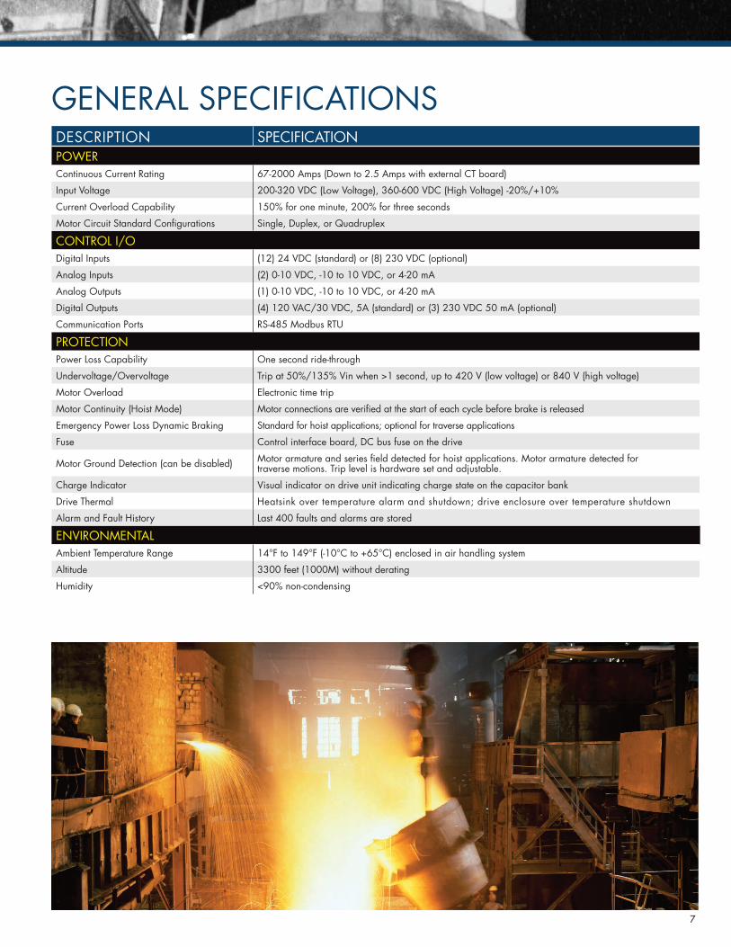
GENERAL SPECIFICATIONSDESCRIPTION SPECIFICATIONPOWERContinuous Current Rating 67-2000 Amps (Down to 2.5 Amps with external CT board)
Input Voltage 200-320 VDC (Low Voltage), 360-600 VDC (High Voltage) -20%/+10%
Current Overload Capability 150% for one minute, 200% for three seconds
Motor Circuit Standard Configurations Single, Duplex, or Quadruplex
CONTROL I/ODigital Inputs (12) 24 VDC (standard) or (8) 230 VDC (optional)
Analog Inputs (2) 0-10 VDC, -10 to 10 VDC, or 4-20 mA
Analog Outputs (1) 0-10 VDC, -10 to 10 VDC, or 4-20 mA
Digital Outputs (4) 120 VAC/30 VDC, 5A (standard) or (3) 230 VDC 50 mA (optional)
Communication Ports RS-485 Modbus RTU
PROTECTIONPower Loss Capability One second ride-through
Undervoltage/Overvoltage Trip at 50%/135% Vin when >1 second, up to 420 V (low voltage) or 840 V (high voltage)
Motor Overload Electronic time trip
Motor Continuity (Hoist Mode) Motor connections are verified at the start of each cycle before brake is released
Emergency Power Loss Dynamic Braking Standard for hoist applications; optional for traverse applications
Fuse Control interface board, DC bus fuse on the drive
Motor Ground Detection (can be disabled) Motor armature and series field detected for hoist applications. Motor armature detected for traverse motions. Trip level is hardware set and adjustable.
Charge Indicator Visual indicator on drive unit indicating charge state on the capacitor bank
Drive Thermal Heatsink over temperature alarm and shutdown; drive enclosure over temperature shutdown
Alarm and Fault History Last 400 faults and alarms are stored
ENVIRONMENTALAmbient Temperature Range 14°F to 149°F (-10°C to +65°C) enclosed in air handling system
Altitude 3300 feet (1000M) without derating
Humidity <90% non-condensing
MAGNETEK HEADQUARTERS US
Toll-Free Phone 800.288.8178Toll-Free Fax 800.298.3503 Phone 262.783.3500Fax 262.783.3510
CANADA FACILITY
Toll-Free Phone 800.792.7253Phone 905.828.1526Fax 905.828.5707
UK FACILITY
Phone +44(0) 1234 349191Fax +44(0) 1234 268955
MH1364_OmniPulse DDC Series 2 Brochure © Magnetek, Inc. 2018
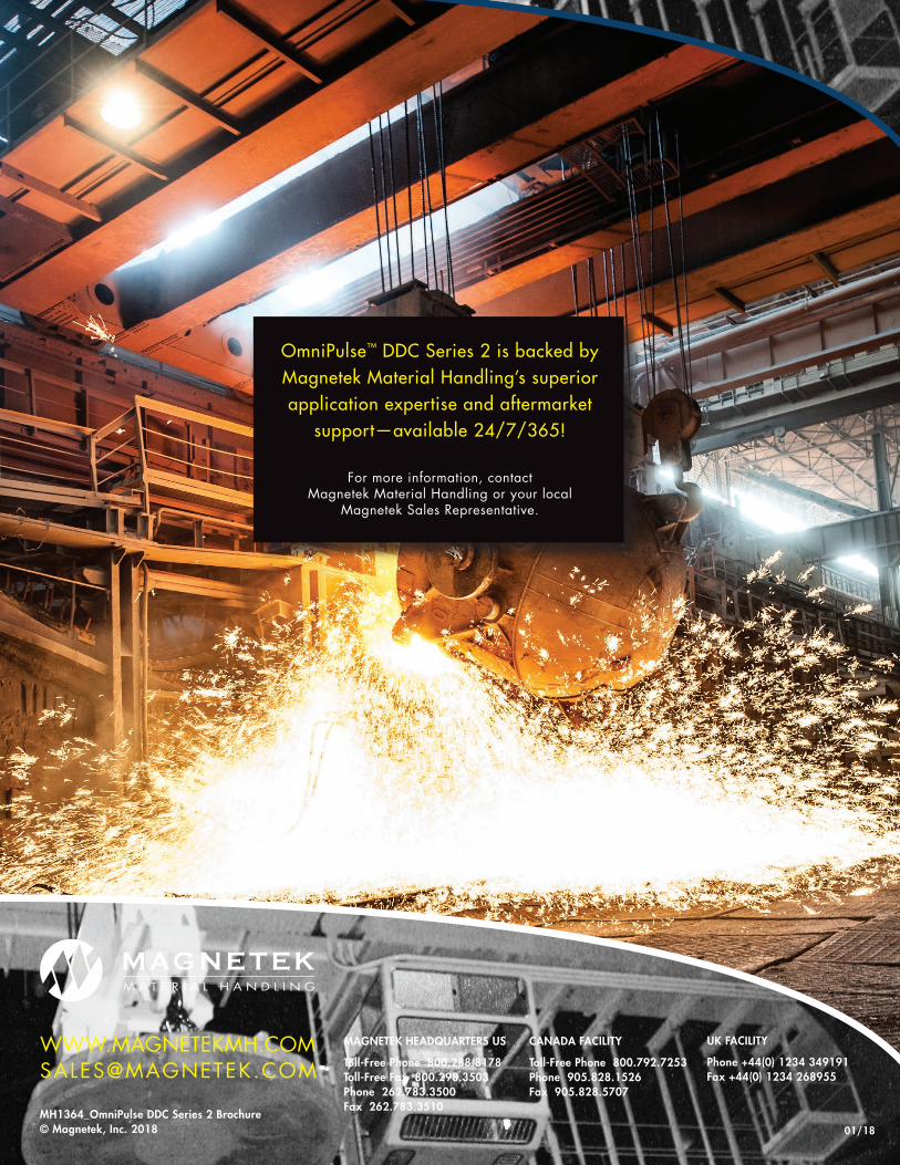
OmniPulse™ DDC Series 2 is backed by Magnetek Material Handling’s superior application expertise and aftermarket
support—available 24/7/365!
For more information, contact Magnetek Material Handling or your local
Magnetek Sales Representative.
01/18