Embed Size (px)
Citation preview
RGB ELEKTRONIKA AGACIAK CIACIEKSPÓŁKA JAWNA Jana Dlugosza 2-6 Street51-162 WrocławPoland
[email protected] +48 71 325 15 05
www.rgbautomatyka.pl
www.rgbelektronika.pl
DATASHEET
www.rgbautomatyka.plwww.rgbelektronika.pl
OTHER SYMBOLS:
BUS622-15/22-54-0-003
BAUMÜLLER

YOUR PARTNER IN MAINTENANCE
At our premises in Wrocław, we have a fully equipped servicing facility. Here we perform all the repair works and test each later sold unit. Our trained employees, equipped with a wide variety of tools and having several testing stands at their disposal, are a guarantee of the highest quality service.
OUR SERVICES
ENCODERS
SERVO DRIVERS
LINEAR ENCODERS
SERVO AMPLIFIERS
CNC MACHINES
MOTORS
POWER SUPPLIERS
OPERATOR PANELS
CNC CONTROLS
INDUSTRIAL COMPUTERS
PLC SYSTEMS
Repair this product with RGB ELEKTRONIKA ORDER A DIAGNOSIS
Buy this product at RGB AUTOMATYKA BUY

E 5.94035.08
Manual
Servo-Power-Unit BUS 621, 622, 623, 624

Title Manual
Product Servo-Power-Unit BUS 621, 622, 623, 624 Version 5.94035.08
Copyright These operating instructions may be copied by the owner in any quantity but only for internal use. For other purposes these operating instructions and extracts thereof must not be copied or reproduced. Use and disclosure of information contained in these oper-ating instructions are not permitted. Designations and company marks contained in these op-erating instructions may be brand names, the use of which by third parties for their own purposes may violate the rights of the holders.
Obligatory These operating instructions are part of the equipment/ma-chine. These operating instructions must be available to the operator at all times and must be in a legible condition. If the equipment/machine is sold or moved to a different lo-cation these operating instructions must be passed on by the owner together with the equipment/machine. After any sale of the equipment/machine this original and all copies must be handed over to the buyer. After disposal or any other end of use this original and all copies must be destroyed.
When the present operating instructions are handed over, corresponding sets of operating instructions of a previous version are automatically invalidated. Please notice that specifications/data/information are current values ac-cording to the printing date. These statements are not legally binding according to the measurement, computa-tion and calculations. Baumüller Nürnberg GmbH reserves the right, in develop-ing its products further, to change the technical specifica-tions and the handling of the products concerned without prior notice.
No liability can be accepted concerning the correctness of the operating instructions unless otherwise specified in the General Conditions of Sale and Delivery.
Manufacturer Baumüller Nürnberg GmbH Ostendstr. 80 - 90 D-90482 Nürnberg Germany Tel. +49 9 11 54 32 - 0 Fax: +49 9 11 54 32 - 1 30 www.baumueller.de

Servo-Power-Unit BUS 621, 622, 623, 624 3 Baumüller Nürnberg GmbH 5.94035.08
TABLE OF CONTENTS
Table of Contents
1 Safety Notes ........................................................................................................ 5
2 Technical Data .................................................................................................... 92.1 General ................................................................................................................................... 9
2.1.1 Function description ..................................................................................................................... 102.1.2 Block diagram .............................................................................................................................. 11
2.2 Electrical data ....................................................................................................................... 122.3 Type code ............................................................................................................................. 13
3 Transport, unpacking ....................................................................................... 15
4 Assembly ........................................................................................................... 174.1 Dimensions ........................................................................................................................... 184.2 Assembly notes .................................................................................................................... 194.3 Attachment ........................................................................................................................... 20
5 Installation ......................................................................................................... 215.1 Hazard notes ........................................................................................................................ 215.2 EMC notes ............................................................................................................................ 215.3 Safety relay ........................................................................................................................... 22
5.3.1 Methods to avoid an unexpected starting .................................................................................... 225.3.2 Safety categories ......................................................................................................................... 235.3.3 The safety relay ........................................................................................................................... 235.3.4 Service time ................................................................................................................................. 27
5.4 Terminal diagram .................................................................................................................. 285.5 Connection pin assignment .................................................................................................. 30
5.5.1 Power terminals ........................................................................................................................... 305.5.2 Control terminals .......................................................................................................................... 31
5.6 Accessories .......................................................................................................................... 32
6 Commisioning ................................................................................................... 336.1 Danger information ............................................................................................................... 336.2 Function diagram .................................................................................................................. 356.3 Operation .............................................................................................................................. 366.4 Messages and warnings ....................................................................................................... 36
7 Maintenance ...................................................................................................... 397.1 Maintenance notes ............................................................................................................... 397.2 Environmental conditions ..................................................................................................... 407.3 Recommissioning ................................................................................................................. 407.4 Disposal ................................................................................................................................ 41
8 Appendix ........................................................................................................... 438.1 Manufacturer Declaration ..................................................................................................... 438.2 Declaration of Conformity ..................................................................................................... 448.3 General Conditions of Sale and Delivery .............................................................................. 468.4 Index ..................................................................................................................................... 50
Abbreviations
4 Servo-Power-Unit BUS 621, 622, 623, 624 5.94035.08 Baumüller Nürnberg GmbH
ABBREVIATIONS
AC Alternation current
AM Asynchronous motor
BUC Baumüller Feed/Feed back Unit
BUG Baumüller Basic Feed Unit
BUM Baumüller Single Power Unit
BUS Baumüller Power Module
DC Direct current
DIN Deutsches Institut für Normung e.V. (German Standardisation Authority)
EMC Elektromagnetic compatibility
EN European standart
HS Main contactor
PELV Protective extra-low voltage
SELV Safe extra-low voltage
MSL Main Sea Level
SL Protective earth
SM Synchronous motor
ZK DC link

Safety Notes
Servo-Power-Unit BUS 621, 622, 623, 624 5 Baumüller Nürnberg GmbH 5.94035.08
1 SAFETY NOTES
Introductory remarks
During operation, the principles on which the converter and motor work, lead to leakage currents to earth which are dissipated via specified protective earth connections and which may result in a current-operated e.l.c.b. on the input side blowing prematurely.A DC component in the fault current may occur in the event of a short-circuit to frame or earth fault which makes a triggering of the higher-level current-operated e.l.c.b. more difficult or even impossible.The connection of the current controller to the mains using only the current-operated e.l.c.b. is prohibited (EN 50178 / VDE 0160 / 4.98, sections 5.2.11 and 5.3.2.1).The units are protected against direct contact by being installed into common switching cabinets which meet the minimum protection requirements according to EN 50178 /VDE 0160 / 4.98, section 5.2.4.Sheets of plastic covering the control electronics, the power stage and the device connection, additionally prevent accidental contact during commissioning and casual use of control elements located close to the equipment. (DIN VDE 0106 Part 100, Accident Prevention Regulation VBG4 ”Electrical Systems and Equipment).The protective measures and safety regulations according to DIN/VDE are binding for personal security. Neglecting to fit PE connections on the equipment or the motor will result in serious personal injury and/or considerable damage to material assets.It is only permitted to use the units on earth-protected supply mains.
The discharge time of live parts is > 1 min.
The units are partly short-circuit-proof.
General information
This manual contains the necessary information for normal operation of the products described therein. It is intended for technically-qualified personnel who are specially trained and are familiar in detail with all warnings and maintenance tasks.
The units are finished to the highest standard and are safe and reliable. They can be installed and oper-ated safely, and function without problem if all information given in this manual are taken into account.
DANGER
Due to the nature of electrical equipment, certain parts of this unit carry dangerous voltage during operation.
Serious injury and/or damage to property can result from non-compliance with these safety notes and warnings.
Only qualified personnel familiar with the safety instructions, and instructions regarding assembly, maintenance and operation are to work on this unit.
Safety Notes
6 Servo-Power-Unit BUS 621, 622, 623, 624 5.94035.08 Baumüller Nürnberg GmbH
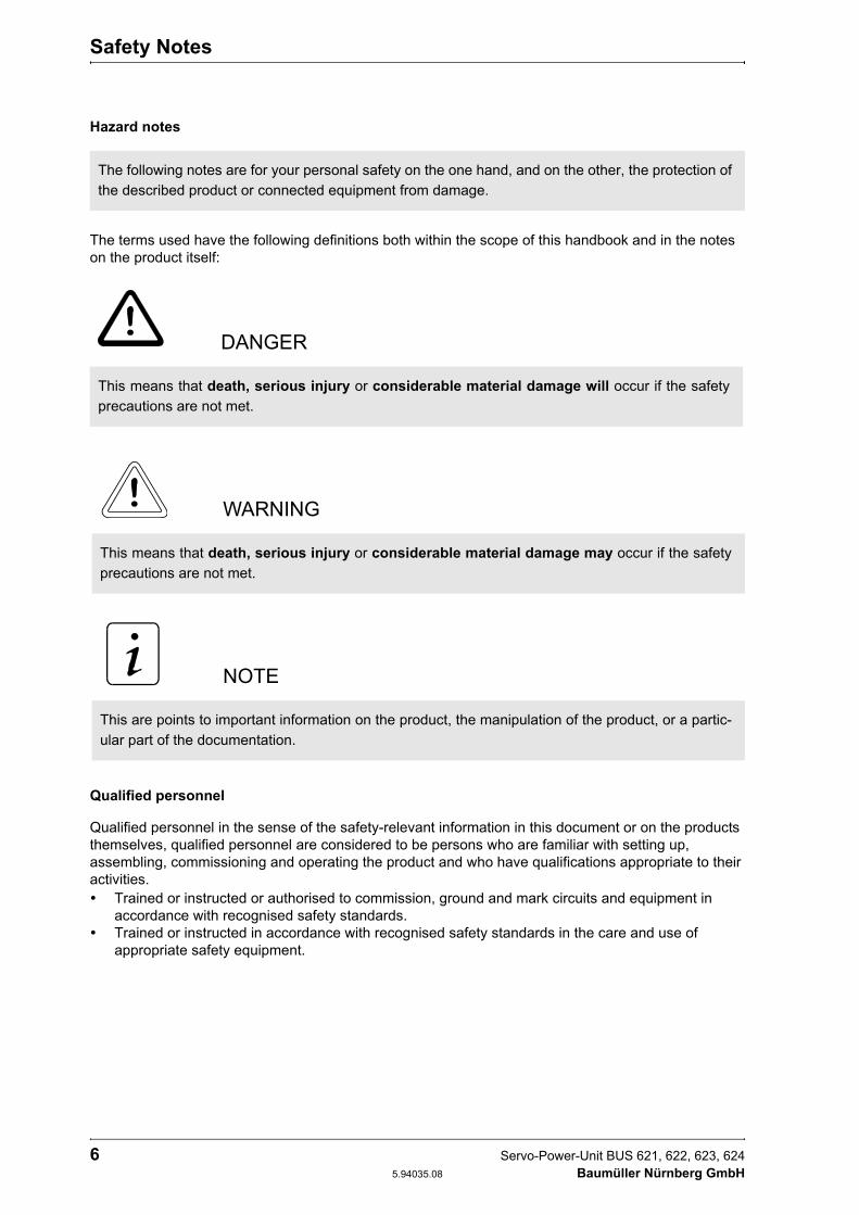
Hazard notes
The terms used have the following definitions both within the scope of this handbook and in the notes on the product itself:
Qualified personnel
Qualified personnel in the sense of the safety-relevant information in this document or on the products themselves, qualified personnel are considered to be persons who are familiar with setting up, assembling, commissioning and operating the product and who have qualifications appropriate to their activities.
Trained or instructed or authorised to commission, ground and mark circuits and equipment in accordance with recognised safety standards.Trained or instructed in accordance with recognised safety standards in the care and use of appropriate safety equipment.
The following notes are for your personal safety on the one hand, and on the other, the protection of the described product or connected equipment from damage.
DANGER
This means that death, serious injury or considerable material damage will occur if the safety precautions are not met.
WARNING
This means that death, serious injury or considerable material damage may occur if the safety precautions are not met.
NOTE
This are points to important information on the product, the manipulation of the product, or a partic-ular part of the documentation.

Safety Notes
Servo-Power-Unit BUS 621, 622, 623, 624 7 Baumüller Nürnberg GmbH 5.94035.08
Normal use
Voltage test
BAUMÜLLER carries out a voltage test according to EN 50178 / VDE0160 / 4.98, Section 9.4.5 for each unit. Subsequent high-voltage tests must only be carried out by Baumüller Nürnberg GmbH.
WARNING
The unit/system may only be used as specified in the system handbook, and only with other units and components recommended or approved by Baumüller Nürnberg GmbH.
Unauthorised conversion of the unit/system is not permitted for safety reasons.
The user is obliged to report any changes which may affect the safety of the unit/system immediately.
WARNING
If you want to carry out high-voltage tests for complete switch cabinet installations, disconnect all cables from Baumüller units prior to the test.

Safety Notes
8 Servo-Power-Unit BUS 621, 622, 623, 624 5.94035.08 Baumüller Nürnberg GmbH

Technical Data
Servo-Power-Unit BUS 621, 622, 623, 624 9 Baumüller Nürnberg GmbH 5.94035.08
2 TECHNICAL DATA
2.1 General
The available power modules BUS 621, BUS 622, BUS 623 and BUS 624 are power amplifier for con-trolling three-phase drives.
The BUS 62X power modules are combined with the rack-mounted controllers of Baumüller Nürnberg GmbH. As a result, the drives can be adapted to a wide variety of requirements.
Depending on the type of application, the units are available as simple frequency converter up to high-dynamic and high-precise vector controllers.
With the digital drive controllers of the BUS 62X series, both asynchronous and synchronous motors with different encoder systems can be driven by the same unit.
The BUS 62X power modules have been constructed using IGBT technology. Their compact construc-tion with 8 kHz clock frequency and its self-protective characteristics are special features of these mo-duels.
As all Baumüller controllers are equipped to be rack-mounted, separate descriptions are available with the respective characteristics and technical data.
Technical Data
10 Servo-Power-Unit BUS 621, 622, 623, 624 5.94035.08 Baumüller Nürnberg GmbH
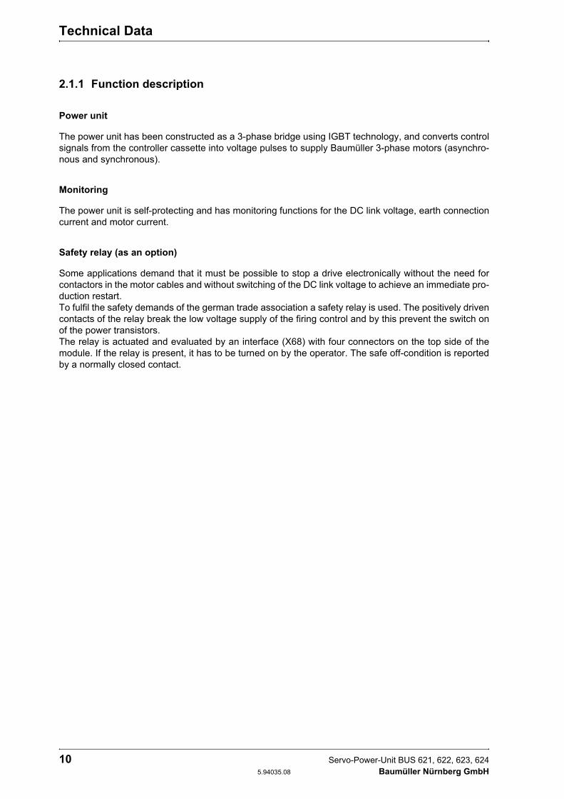
2.1.1 Function description
Power unit
The power unit has been constructed as a 3-phase bridge using IGBT technology, and converts control signals from the controller cassette into voltage pulses to supply Baumüller 3-phase motors (asynchro-nous and synchronous).
Monitoring
The power unit is self-protecting and has monitoring functions for the DC link voltage, earth connection current and motor current.
Safety relay (as an option)
Some applications demand that it must be possible to stop a drive electronically without the need for contactors in the motor cables and without switching of the DC link voltage to achieve an immediate pro-duction restart. To fulfil the safety demands of the german trade association a safety relay is used. The positively driven contacts of the relay break the low voltage supply of the firing control and by this prevent the switch on of the power transistors. The relay is actuated and evaluated by an interface (X68) with four connectors on the top side of the module. If the relay is present, it has to be turned on by the operator. The safe off-condition is reported by a normally closed contact.

Technical Data
Servo-Power-Unit BUS 621, 622, 623, 624 11 Baumüller Nürnberg GmbH 5.94035.08
2.1.2 Block diagram

Technical Data
12 Servo-Power-Unit BUS 621, 622, 623, 624 5.94035.08 Baumüller Nürnberg GmbH
2.2 Electrical data
* not supplied, must be ordered separately
1. According to EN 61131-2 (Table 5). With a supply voltage < 24 V the fan power is reduced. There-fore, it may be necessary to reduce the output current additonally.
2. depends on the connected DC Link capacity.
Power unit BUS 621 BUS 622 BUS 623 BUS 624
Control * Slot for BUS 6 controller cassette
DC link voltage nominal value maximum (< 2 min)
0 ... 685 VDC540 VDC760 VDC
Low voltage supply for controller and 1) moitoring functions
+ 24 VDC - 10% + 20%
Power input without controller 22 W 22 W 27 W 39 W
Capacitor DC Link 50 µF 110 µF 235 µF 500 µF
Switch on: Ready for use after 2) ≤ 10 s
Output voltage 3) 3 x 0 VAC ... connection voltage BUG - 30 V resp. 3 x 0,74 • DC link voltage
Output frequency 0 Hz ... 300 Hz
Output power 4) 1,4 kVA 3,5 kVA 7 kVA 10,5 kVA 14 kVA 26 kVA 31 kVA
Typ. motor power 4) 0,8 kW 2 kW 4 kW 6 kW 8 kW 15 kW 20 kW
Typ. motor max. power 5) 1,2 kW 3 kW 6 kW 9 kW 12 kW 23 kW 30 kW
Output nominal current (Ieff) 4) 6) 2 A 5 A 10 A 15 A 20 A 38 A 45 A
Output max. current (Ieff) 6) 7) 3 A 7,5 A 15 A 22 A 30 A 55 A 67 A
permitted transistor clock frequency 3 ... 8 kHz
Power loss during rated operation 4)
without low voltage supply30 W 75 W 150 W 170 W 230 W 450 W 550 W
safety relay (as an option) coil side nominal voltage
operating voltage coil resistance
contact side max. switching voltage max. switching current max. switching capacity
24 V (SELV)18,4 V to 50,4 V at Tu = 20 °C
1300 Ω ±10 %25 VAC resp. 60 VDC (SELV)
5 A (max. permanent current 6 A)1500 VAAC / 30 WDC
type of protection IP 20
Operational environment range TB 0 ... 40 °C (with power reduction 55 °C)
Reduction for nominal output current (45 ... 55 °C)
0 % / °C 3 % / °C
Installation hight 8) 1000 m above sea level
Relative humidity 15 % ... 85 % nicht betaut
Storage temperature range - 30 °C ... + 70 °C
Short circuit proof partly short circuit proof
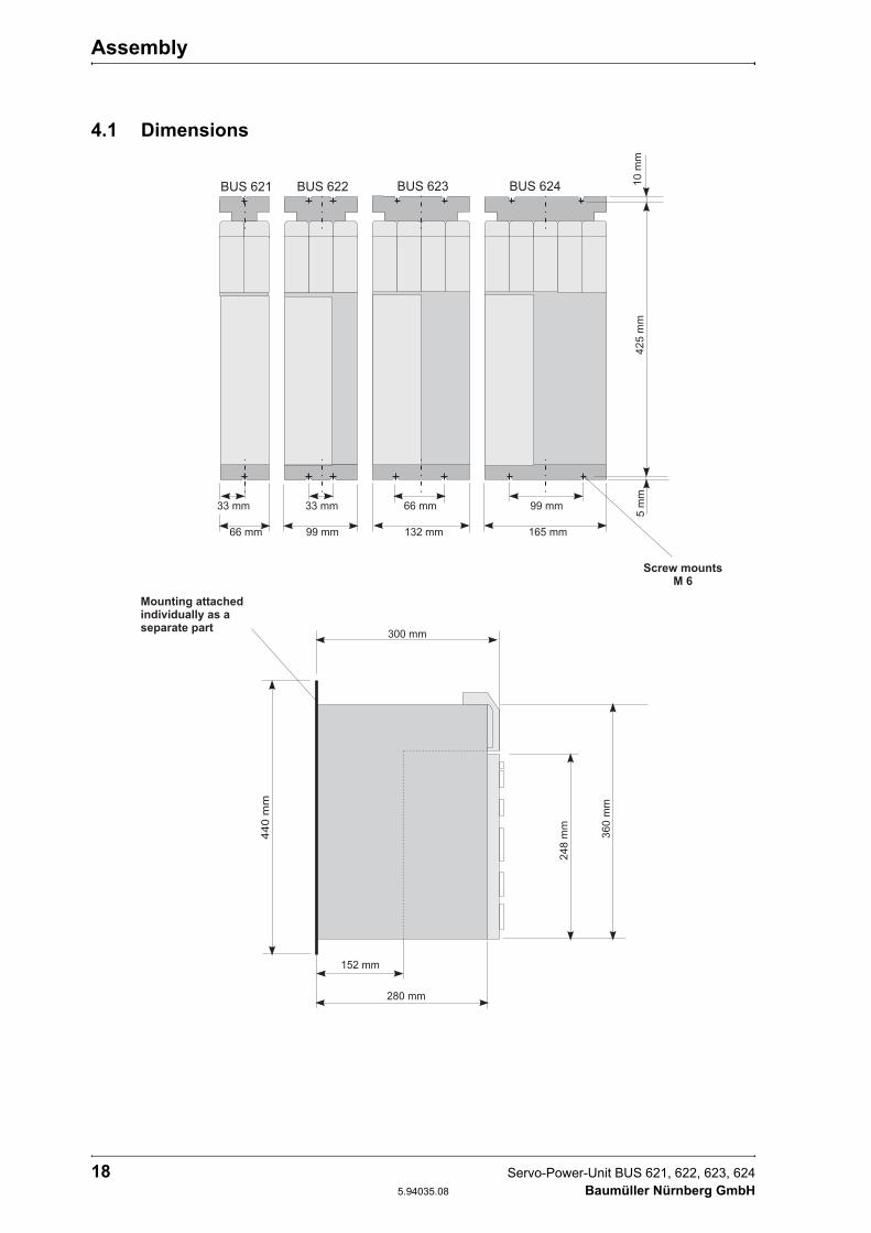
Dimensions Width 66 mm 99 mm 132 mm 165 mm
Height 360 mm
Depth 280 mm
Weight without controller 5 kg 7,5 kg 10 kg 12,5 kg

Technical Data
Servo-Power-Unit BUS 621, 622, 623, 624 13 Baumüller Nürnberg GmbH 5.94035.08
3. The output voltage is a pulse-commutated DC. The setting range refers to the r.m.s. value of the fun-damental wave.
4. at DC Link voltage 540 VDC
5. for max. 1 s
6. The unit provides the rated/maximum output current up to the connection voltage. When the input voltage exceeds the rated voltage, reduce the output currents at constant output power proportional-ly.
Characteristic 1: Output currents in relation to the connection voltage
7. Maximum duration of the peak output current is 1 s. The duration depends on the motor current and the temperature of the heat sink. See Technical Description/Operating Instructions of the controller (V-controller: P139).
8. Characteristic curve for output reduction depending on installation height see technical data of sup-ply unit
2.3 Type code

Technical Data
14 Servo-Power-Unit BUS 621, 622, 623, 624 5.94035.08 Baumüller Nürnberg GmbH
Transport, unpacking
Servo-Power-Unit BUS 621, 622, 623, 624 15 Baumüller Nürnberg GmbH 5.94035.08
3 TRANSPORT, UNPACKING
The units are packed in the manufacturer´s works in accordance with ordering instructions.
Severe vibrations during transport are to be avoided.
Once packaging is removed and the devices are checked for their completeness, assembly can follow.
Packaging material consists of cardboard, corrugated cardboard and/or wood. It can be disposed of in accordance with local disposal regulations.
Any transport damage should be reported.
DANGER
In the event of damage being sustained in transit, the unit should no be connected to a supply without prior (high voltage) testing trained personnel.
Death, serious injury or considerable damage to equipment may result should this warning fail to be heeded.

Transport, unpacking
16 Servo-Power-Unit BUS 621, 622, 623, 624 5.94035.08 Baumüller Nürnberg GmbH

Assembly
Servo-Power-Unit BUS 621, 622, 623, 624 17 Baumüller Nürnberg GmbH 5.94035.08
4 ASSEMBLY
WARNING
The user is responsible for the assembly of the converter power unit, the motor and the other compo-nents according to applicable safety standards (e.g. DIN, VDE) and all other relevant national or local regulations regarding conductor dimensions and fusing, grounding, circuit breakers, overcurrent pro-tection etc.
A space must be left above and below the units, and sufficient cool air and air circulation must be pro-vided.
Sheets of plastic on the devices that cover the equipment connection act as additional guards pre-venting accidental contact at commissioning and in the case of casual use of control elements located close to the equipment (DIN VDE 0106 Part 100, Accident Prevention Regulation VBG4 "Electrical Systems and Equipment").
Pollution degree 3 and 4 according to EN 50178/VDE0160/4.98 Section. 5.2.15.2 must be avoided. The units are suitable for the installation in closed operating rooms. (VDE 0558 Part 1a, Section 5.4.3.2.1 and 5.4.3.2.2
Assembly
18 Servo-Power-Unit BUS 621, 622, 623, 624 5.94035.08 Baumüller Nürnberg GmbH
4.1 Dimensions

Assembly
Servo-Power-Unit BUS 621, 622, 623, 624 19 Baumüller Nürnberg GmbH 5.94035.08
4.2 Assembly notes
The units must be installed in the switch cabinet vertically. The power module BUS 62x must be ar-ranged near to the feed / feed back unit BUC 622, 623 or the basic feed unit BUG 622, 623 and the DC Link must be connected by the connection bars supplied with the unit. When delivered, the con-nection bars are fastened to the front bars of the units BUS 62x.
Ventilation must be from bottom to top.
Unrestricted ventilation must be guaranteed.
A space of at least 100 mm
must be left above and below the units, and sufficient cool air and air circulation is to be provided.
Coolant temperature 50 mm under the units, up to 40 °C. With higher temperatures (up to max. 55 °C), power output of the units must be reduced by 3 % per °C.
Do not locate any additional sources of heat above or below the units.
WARNING
Not appropriate heave can lead to injury or damage. The unit must be heaved by appropriate device and with qualified personnel.
DANGER
Longer connections are not permitted, as they may cause damage to the equipment. The discharge time of live parts is > 1 min.
WARNING
The following measures must be strictly observed to avoid the danger of device overheating.

Assembly
20 Servo-Power-Unit BUS 621, 622, 623, 624 5.94035.08 Baumüller Nürnberg GmbH
4.3 Attachment
1. Attach the mounting backplate to the control cabinet (for sizes, see "Dimensions"). The backplate can be used as a mounting and drilling template. The backplates of neighbouring units must be directly next to one another.
2. Push back the retaining plate spring and hang the unit in place. The unit is then held fast between the mounting backplate and the back wall.
3. To dismount the unit, press the retaining plate spring and lift out upwards.

Installation
Servo-Power-Unit BUS 621, 622, 623, 624 21 Baumüller Nürnberg GmbH 5.94035.08
5 INSTALLATION
5.1 Hazard notes
5.2 EMC notes
can be found in the manual or the basic feed unit.
WARNING
This unit carries dangerous voltage and contains dangerous rotating machine parts (ventilators). This means that death, serious injury or considerable material damage can occur if the safety and warning notes are not heeded.
The user is responsible for the assembly of the converter power unit, the motor, the mains filter and the other components according to applicable safety standards (e.g. EN, DIN) and all other relevant national or local regulations regarding conductor dimensions and fusing, grounding, circuit breakers, overcurrent protection etc.
High leakage to ground occurs in the converter and the motor, i.e. the drive may be incompatible with residual current protective devices(EN 50178:1998 / VDE0160:4.98 sect. 5.2.11.2).
Variable-speed drives may only be used if their use conforms to valid EN regulations.
DANGER
The DC Link carries electrical potential: it is imperative that the provided cover is used.
Setial care is needed when touching the drive shaft, directly or indirectly (by hand). This should only be done in a voltage free state and whilst the drive is stationary.
Safety equipment must under no circumstances be shut down.

Installation
22 Servo-Power-Unit BUS 621, 622, 623, 624 5.94035.08 Baumüller Nürnberg GmbH
5.3 Safety relay
In this chapter we describe the safety relay.
5.3.1 Methods to avoid an unexpected starting
In order to avoid hazards against persons, for example operators, service- and maintenance technics, the machine has to be kept in a secure condition (safe stop), while interfering in the hazardous area of the machine. That is why a reliable prevention of an unexpected starting is demanded (amongst other things Machine directive 89/392/EWG, appendix I, 1.6.3, last passage; EN 292-2, 4.1.4; EN 60204-1, 5.4). Under unexpected starting is to be understood every starting that can cause a risk when appearing unexpected for persons (EN 292-1). Moreover, besides the transition of the release- to the operating condition of the machine also the unexpected ramp-up of the machine, this means the transition from the safe stop into an unsafe moving has to be considered. This is necessary, because the unexpected ramp-up usually is to be led back to an interruption of the control loop of the machine. In this case the drive is, because of its control system, anxious to achieve highest speed at maximal acceleration. If an unexpected starting occurs, the operator therefore doesn’t have the possibility anymore to remove him-self or his hand from the hazard area. This is why the drive has to be stopped and has to be kept safe in its ’off-position’, when having opened, electrical interlocked safety devices. The motor may not have torque and thus cannot generate a dangerous movement.
The prevention of an unexpected starting of the machine can be reached by electrical separated safety devices, e.g. contactors. By some machine types it has to be done without the isolation of the electrical connection of the drive to the mains, if e. g. a drive supplied by a power converter is often stopped and started again. The constant dis- and re-charging of the DC-link represents a big stress for the concerned parts and often leads to disturbing delays and failures of these parts.
The requirement for the starting of a three-phase a. c. motor is the generation of a rotating field, which drives the inductor of the motor. When having variable-speed three-phase current drives, usually in the micro-processors a complex pulse pattern is generated, then the pulses are amplified and are used for the switching of the power semiconductors. If either no defined pulse pattern is available or the amplify-ing connection is interrupted, e. g. by switching off of the power supply with a relay (safety relay), no rotary field can be generated. An error by the pulse pattern generation therefore cannot lead to a starting of the motor, as long as the second condition, namely the interruption of the amplifying power supply is available and contrary. The protection against unexpected starting is reached by an electromechanical method which is superior to the electronics. It is reached by a safe isolation - elsewhere than in the load circuit.
The power supply to the windings of the motor is reached at a stoppage by inhibiting the power semi-conductor. As semiconductors possibly can fail or be started, because of electromagnetic disturbances, the behaviour of the shut down drive has to be considered if such a fault scenario arises. The fail or "ac-cidental" turning on of a single or of more power semiconductors at the same DC-link pole does not lead to an uncontrolled starting, as no current flow is accomplished. Not until additionally a further power sem-iconductor is enabled at another DC-link pole, current is able to flow through the motor. If, thereby the DC-link is directly short-circuited, the fuses which are upstreamed to the converter are tripped, the motor doesn’t start. If the DC-link is "short-circuited" over a winding of the motor, a magnetic field can be set up in the motor. If it is an asynchronous motor, then the generated d. c. magnetic properties cannot cause a lurch of the inductor. By the permanent-magnetic synchronous motor the inductor will rotate into a notch position. The therewith angular movement which is covered is dependable of the inductor’s po-sition and the number of pole pairs of the motor. It amounts to maximal 180°/number of pole pairs. Sub-sequently the enabled DC-link operates like a brake, this means after the ending of the lurching movement the drive is in a blocked condition. A starting of the drive is impossible. If a machine with a synchronous motor is planned, the possible sudden movement must be considered, because it can lead to a dangerous movement. Therefore the machinist must carry out a safety evaluation for the residual movement.
Installation
Servo-Power-Unit BUS 621, 622, 623, 624 23 Baumüller Nürnberg GmbH 5.94035.08
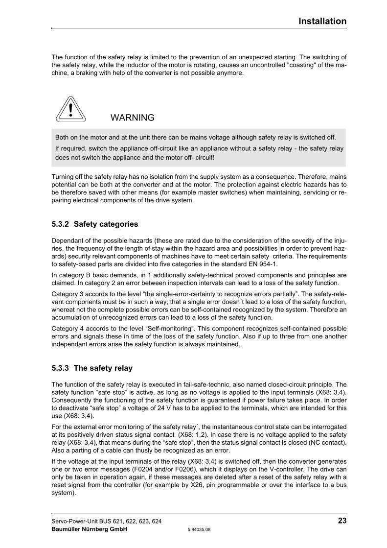
The function of the safety relay is limited to the prevention of an unexpected starting. The switching of the safety relay, while the inductor of the motor is rotating, causes an uncontrolled "coasting" of the ma-chine, a braking with help of the converter is not possible anymore.
Turning off the safety relay has no isolation from the supply system as a consequence. Therefore, mains potential can be both at the converter and at the motor. The protection against electric hazards has to be therefore saved with other means (for example master switches) when maintaining, servicing or re-pairing electrical components of the drive system.
5.3.2 Safety categories
Dependant of the possible hazards (these are rated due to the consideration of the severity of the inju-ries, the frequency of the length of stay within the hazard area and possibilities in order to prevent haz-ards) security relevant components of machines have to meet certain safety criteria. The requirements to safety-based parts are divided into five categories in the standard EN 954-1.
In category B basic demands, in 1 additionally safety-technical proved components and principles are claimed. In category 2 an error between inspection intervals can lead to a loss of the safety function.
Category 3 accords to the level “the single-error-certainty to recognize errors partially”. The safety-rele-vant components must be in such a way, that a single error doesn´t lead to a loss of the safety function, whereat not the complete possible errors can be self-contained recognized by the system. Therefore an accumulation of unrecognized errors can lead to a loss of the safety function.
Category 4 accords to the level “Self-monitoring”. This component recognizes self-contained possible errors and signals these in time of the loss of the safety function. Also if up to three from one another independant errors arise the safety function is always maintained.
5.3.3 The safety relay
The function of the safety relay is executed in fail-safe-technic, also named closed-circuit principle. The safety function “safe stop” is active, as long as no voltage is applied to the input terminals (X68: 3,4). Consequently the functioning of the safety function is guaranteed if power failure takes place. In order to deactivate “safe stop” a voltage of 24 V has to be applied to the terminals, which are intended for this use (X68: 3,4).
For the external error monitoring of the safety relay´, the instantaneous control state can be interrogated at its positively driven status signal contact (X68: 1,2). In case there is no voltage applied to the safety relay (X68: 3,4), that means during the “safe stop”, then the status signal contact is closed (NC contact). Also a parting of a cable can thusly be recognized as an error.
If the voltage at the input terminals of the relay (X68: 3,4) is switched off, then the converter generates one or two error messages (F0204 and/or F0206), which it displays on the V-controller. The drive can only be taken in operation again, if these messages are deleted after a reset of the safety relay with a reset signal from the controller (for example by X26, pin programmable or over the interface to a bus system).
WARNING
Both on the motor and at the unit there can be mains voltage although safety relay is switched off.
If required, switch the appliance off-circuit like an appliance without a safety relay - the safety relay does not switch the appliance and the motor off- circuit!

Installation
24 Servo-Power-Unit BUS 621, 622, 623, 624 5.94035.08 Baumüller Nürnberg GmbH
The closing- and opening sequence of the release signals as well as of the safety relay must be consid-ered in order to assure a faultless operation of the drive.
Sequence diagram of the safety relay
Baumüller-devices of the series BUM 6, BUS 6 and BKH, which are made with one safety relay (option-al), comply with the requirements of the category 3 (EN 954-1) for the safety-relevant using “protection against unexpected starting”, if the configuring and installation instructions are complied with.
Before the commissioning of the machine, in which the converter with the safety relay is built in, the safe-ty function “protection against unexpected starting” must be checked. For that purpose a safety device must be executed (for example door contact). The motor must now be zero-torque.
If the reliability performance of the “protection of unexpected starting” once has been determined, then this safety function of the converter doesn´t have to be checked by an external monitoring, as the device checks itsself on possible errors and if necessary displays a message as well as turns off the drive.
Installation
Servo-Power-Unit BUS 621, 622, 623, 624 25 Baumüller Nürnberg GmbH 5.94035.08
Application example for machine of category 3
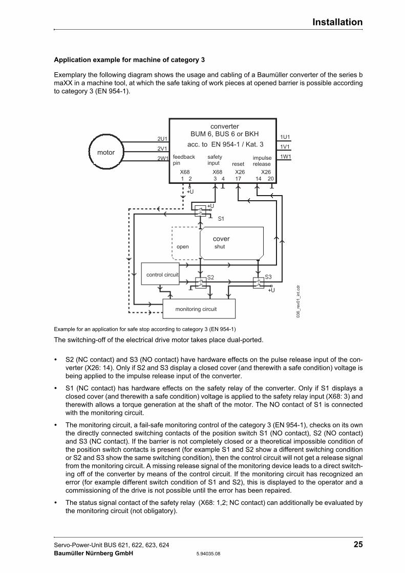
Exemplary the following diagram shows the usage and cabling of a Baumüller converter of the series b maXX in a machine tool, at which the safe taking of work pieces at opened barrier is possible according to category 3 (EN 954-1).
Example for an application for safe stop according to category 3 (EN 954-1)
The switching-off of the electrical drive motor takes place dual-ported.
S2 (NC contact) and S3 (NO contact) have hardware effects on the pulse release input of the con-verter (X26: 14). Only if S2 and S3 display a closed cover (and therewith a safe condition) voltage is being applied to the impulse release input of the converter.
S1 (NC contact) has hardware effects on the safety relay of the converter. Only if S1 displays a closed cover (and therewith a safe condition) voltage is applied to the safety relay input (X68: 3) and therewith allows a torque generation at the shaft of the motor. The NO contact of S1 is connected with the monitoring circuit.
The monitoring circuit, a fail-safe monitoring control of the category 3 (EN 954-1), checks on its own the directly connected switching contacts of the position switch S1 (NO contact), S2 (NO contact) and S3 (NC contact). If the barrier is not completely closed or a theoretical impossible condition of the position switch contacts is present (for example S1 and S2 show a different switching condition or S2 and S3 show the same switching condition), then the control circuit will not get a release signal from the monitoring circuit. A missing release signal of the monitoring device leads to a direct switch-ing off of the converter by means of the control circuit. If the monitoring circuit has recognized an error (for example different switch condition of S1 and S2), this is displayed to the operator and a commissioning of the drive is not possible until the error has been repaired.
The status signal contact of the safety relay (X68: 1,2; NC contact) can additionally be evaluated by the monitoring circuit (not obligatory).

Installation
26 Servo-Power-Unit BUS 621, 622, 623, 624 5.94035.08 Baumüller Nürnberg GmbH
The position switches, which are used, must unavoidable have actuated and mechanical connected contacts as well as a dual-port connection (NC contact/ NO contact). The mechanical operating at the safety device must take place unavoidable, that means tamper-resistant.
The connection cables between the safety relay input (X68: 3,4) and the control as well as between the impulse release input at the converter (X3:5) and the controller must not be installed outside the control cabinet in a common cable channel.
Application example for machine of category 4
Additional procedures when configuring a machine make it possible with a converter of the category 3 (EN 954-1) at safety-relevant operations for the “protection against unexpected starting” also category 4 for the complete drive.
A possibility is the usage of a contactor, with which the external conductors of the motor cable is short-circuited.
The diagram shows exemplary the usage and cabling of a Baumüller converter of the series BUM 6, BUS 6 or BKH of a machine tool, at which the safe taking of work pieces at opened barrier according to cat-egory 4 (EN 954-1) is possible.
Example for an application for safe stop according to category 4 (EN 954-1)
The switching-off of the electrical drive motor takes place three-ported.
The contactor K1 with three NC contacts short-circuits the current to the motor in the release state in all poles (closed-circuit current principle), so that no electrical energy of the converter arrives at the motor. S2 (NC contact) and S3 (NO contact) effectuate K1. Only if S2 and S3 display a closed barrier (and therewith a safe condition) K1 starts up and the short-circuit in the motor line is reset.

Installation
Servo-Power-Unit BUS 621, 622, 623, 624 27 Baumüller Nürnberg GmbH 5.94035.08
The status signal contact of K1 (NO contact) to the monitoring circuit is constructed with mechanical with the NC contacts connected contacts. The selection of the contactor takes place after its limiting short-time current load capability (10 ms). This must be bigger than the nominal current of the used semiconductor fuses at the mains input of the converter.
S1 (NC contact) has hardware effects on the safety relay of the converter. Only then if S1 displays a closed barrier (and therewith a safe condition) voltage is applied to the safety relay input (X68: 3) and therewith makes a torque generation at the shaft of the motor. The NO contact of S1 is connect-ed with the monitoring circuit.
S3 (NO contact) has hardware effects on the impulse release input of the converter (X26: 14). Only if S3 displays a closed barrier (and therewith a safe condition) voltage is applied to the impulse re-lease input of the converter.
The monitoring circuit, a fail-safe monitoring control of the category 4 (EN 954-1), checks on its own the directly connected switch contacts of the position switches S1 (NO contact), S2 (NO contact), S3 (NC contact) and the status signal contact of the safety relay (X68: 1,2; NC contact) as well as the contactor K1 (NO contact). If the barrier is not completely closed or a theoretic impossible condition of the position switch contacts is present (for example S1 and S2 show a different switch condition or S2 and S3 show the same switch condition or the status signal contact of the safety relay is opened/closed, although the status signal contact of S1 is closed/opened), the control circuit re-ceives no release signal of the monitoring signal. A missing release signal of the monitoring device leads to a direct switching off of the converter by means of the control circuit. If the monitoring circuit has recognized an error (for example different switch condition of S1 and S2), this if displayed to the operator and the commissiong of the drive is not possible until the error has been repaired.
The position switches, which are used, must unavoidable have actuated and mechanical connected contacts as well as a dual-port connection (NC contact/ NO contact). The mechanical operating at the safety device must take place unavoidable, that means tamper-resistant.
The connection cables between the contactor K1 and the control circuit as well as between the safety relay input at the converter (X68: 3,4) and the control circuit must not be installed outside the switching cabinet in a common cable channel.
5.3.4 Service time
The mechanical service time of the safety relay is at least 1 x 10⁷ cycles of operation.
NOTE
All information given in the Operation Manual of the converter, especially the chapters safety instruc-tion, installation and commissioning, must absolutely be observed.
For the use and the installation of the safety devices the legal and official requirements of the gov-ernment safety organizations and of the EU-Directives for safety requirements at installations and machines (for example EN 60204-1, security of machines, electric equipment and EN 292-2 security of machines general configuration directives) are valid.

Installation
28 Servo-Power-Unit BUS 621, 622, 623, 624 5.94035.08 Baumüller Nürnberg GmbH
5.4 Terminal diagram
Installation
Servo-Power-Unit BUS 621, 622, 623, 624 29 Baumüller Nürnberg GmbH 5.94035.08
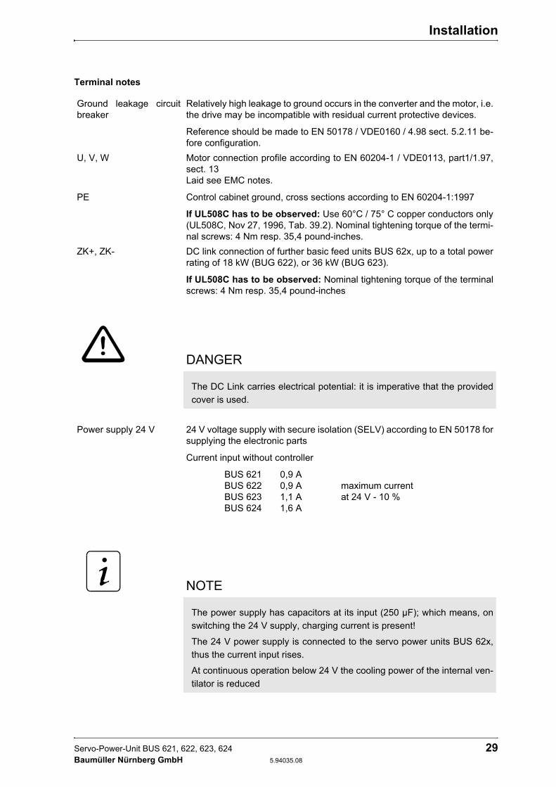
Terminal notes
Ground leakage circuit breaker
Relatively high leakage to ground occurs in the converter and the motor, i.e. the drive may be incompatible with residual current protective devices.
Reference should be made to EN 50178 / VDE0160 / 4.98 sect. 5.2.11 be-fore configuration.
U, V, W
PE
Motor connection profile according to EN 60204-1 / VDE0113, part1/1.97, sect. 13 Laid see EMC notes.
Control cabinet ground, cross sections according to EN 60204-1:1997
If UL508C has to be observed: Use 60°C / 75° C copper conductors only (UL508C, Nov 27, 1996, Tab. 39.2). Nominal tightening torque of the termi-nal screws: 4 Nm resp. 35,4 pound-inches.
ZK+, ZK- DC link connection of further basic feed units BUS 62x, up to a total power rating of 18 kW (BUG 622), or 36 kW (BUG 623).
If UL508C has to be observed: Nominal tightening torque of the terminal screws: 4 Nm resp. 35,4 pound-inches
DANGER
The DC Link carries electrical potential: it is imperative that the provided cover is used.
Power supply 24 V 24 V voltage supply with secure isolation (SELV) according to EN 50178 for supplying the electronic parts
Current input without controller
BUS 621 0,9 A BUS 622 0,9 A maximum current BUS 623 1,1 A at 24 V - 10 % BUS 624 1,6 A
NOTE
The power supply has capacitors at its input (250 µF); which means, on switching the 24 V supply, charging current is present!
The 24 V power supply is connected to the servo power units BUS 62x, thus the current input rises.
At continuous operation below 24 V the cooling power of the internal ven-tilator is reduced
Installation
30 Servo-Power-Unit BUS 621, 622, 623, 624 5.94035.08 Baumüller Nürnberg GmbH
5.5 Connection pin assignment
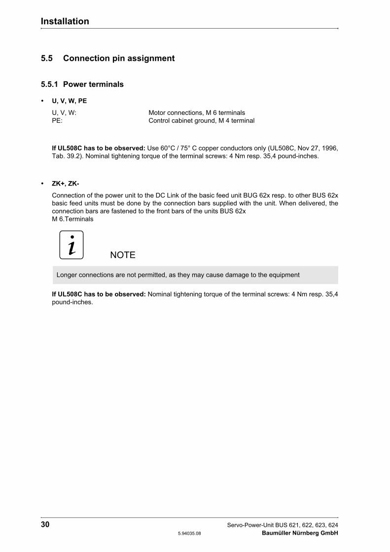
5.5.1 Power terminals
U, V, W, PE
U, V, W: Motor connections, M 6 terminals PE: Control cabinet ground, M 4 terminal
If UL508C has to be observed: Use 60°C / 75° C copper conductors only (UL508C, Nov 27, 1996, Tab. 39.2). Nominal tightening torque of the terminal screws: 4 Nm resp. 35,4 pound-inches.
ZK+, ZK-
Connection of the power unit to the DC Link of the basic feed unit BUG 62x resp. to other BUS 62x basic feed units must be done by the connection bars supplied with the unit. When delivered, the connection bars are fastened to the front bars of the units BUS 62x M 6.Terminals
If UL508C has to be observed: Nominal tightening torque of the terminal screws: 4 Nm resp. 35,4 pound-inches.
NOTE
Longer connections are not permitted, as they may cause damage to the equipment

Installation
Servo-Power-Unit BUS 621, 622, 623, 624 31 Baumüller Nürnberg GmbH 5.94035.08
5.5.2 Control terminals
Terminal strip X99A/X99B
All terminals are connected to each other (i.e. terminal 1 of X99A is connected to terminal 1 of X99B ...). Because of this they can be used as BUS-connection from one Baumüller unit to the other.
The signals can be executed as a bus connection, due to the connection of X99A with X99B of the next unit in the line.
Recommended connection lead length - 44 mm.
WARNING
All control voltages applied externally must be PELV or SELV
X 99 A
X 99 B
Terminal no. Assignment
1, 2 + 24 V (PELV) Terminal for power supply to the units,
both terminals internally bypassed, 2nd terminal with power supply current > 10 A
3, 4 Ground 24 V (PELV) Terminal for power supply to the units,
both terminals internally bypassed,2nd terminal with power supply current > 10 A
5 Ready for use, internalReady for use message from the supply
converter to all units attached to the DC link.
6 Reserved (PELV)
WARNING
A maximum current greater than 10 A per single terminal may cause damage to the equipment. If higher currents are needed do build a multiple feeder system.
Installation
32 Servo-Power-Unit BUS 621, 622, 623, 624 5.94035.08 Baumüller Nürnberg GmbH
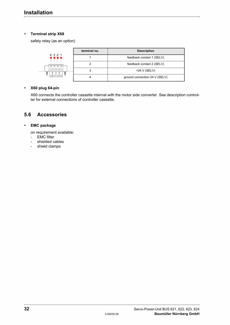
Terminal strip X68
safety relay (as an option)
X60 plug 64-pin
X60 connects the controller cassette internal with the motor side converter. See description control-ler for external connections of controller cassette.
5.6 Accessories
EMC package
on requirement available: - EMC filter - shielded cables - shield clamps
terminal no. Description
1 feedback contact 1 (SELV)
2 feedback contact 2 (SELV)
3 +24 V (SELV)
4 ground connection 24 V (SELV)

Commisioning
Servo-Power-Unit BUS 621, 622, 623, 624 33 Baumüller Nürnberg GmbH 5.94035.08
6 COMMISIONING
6.1 Danger information
WARNING
This unit carries dangerous voltage and contains dangerous rotating machine parts (ventilators). This means that death, serious injury or considerable material damage can occur if the safety and warning notices are not heeded.
The user is responsible for the assembly of the converter power unit, the motor, the mains filter and the other components according to applicable safety standards (e.g. EN, DIN) and all other relevant national or local regulations regarding conductor dimensions and fusing, grounding, circuit breakers, overcurrent protection etc.
The protective measures and safety regulations according to DIN/VDE are binding for personal secu-rity. If there are no PE connections on the unit, the mains filter or the motor, personal injury may be caused since the surface may carry hazardous voltage.
Relatively high leakage to ground occurs in the converter and the motor, i.e. the drive may be incom-patible with a current operated e.l.c.b.
.A DC component in the fault current may occur in the event of a short-circuit to frame or earth fault which makes a triggering of the higher-level current-operated e.l.c.b. more difficult or even impossible.
Make the PE connection according to EN 60204-1 / VDE 0113 Part 1 / 01.97; Section 8.2.2 considering EN 50178 / VDE 0160/ 4.98, Sections 5.3.2.1 and 8.3.4.4.
Before commissioning check whether the plastic covers over the live parts (power part connections) are in place.
When an error occurs, the drive is de-energised and the motor coasts to stop. This fact must be taken into account particularly for hoist and lifting drives.
Commisioning
34 Servo-Power-Unit BUS 621, 622, 623, 624 5.94035.08 Baumüller Nürnberg GmbH
WARNUNG
Prior to connecting the drive, carefully check all higher-level safety equipment for perfect functioning, to avoid personal injury.
Behaviour of the drive in the event of error
Faulty or uncontrolled drive and machine element movement can not be ruled out during initial com-missioning. Hence special care must be taken.
Protection against contact according to Paragraph 4 Section 4 VBG 4
Protection against direct contact comprises all measures against danger which can result from touching the active parts of electrical equipment.
Sheets of plastic covering the control electronics, the power stage and the device connection, addi-tionally prevent accidental contact during commissioning and casual use of control elements located close to the equipment.(DIN VDE 0106 Part 100, Unfallverhütungsvorschrift „Elektrische Anlagen und Betriebsmittel“ VBG4)
Switch cabinet must have emergency stop facilities using which all voltages causing dangerous situ-ations, can be switched off. This does not include equipment which, if switched off, would cause an-other dangerous situation. The releasing element for the emergency stop facility must be arranged such that it can easily be reached in case of danger. In the event of work which is considerably more dangerous that usual, another person must be present.
The user has to ensure that no unauthorised persons work on the machine.
The user is obliged to report any changes which may affect the safety of the machine.
On dismantling safety equipment during commissioning, repair and maintenance, the machine is to be shut down exactly according to instructions. After completion of commissioning, repair and mainte-nance work the safety equipment is to be reinstalled and checked immediately.

Commisioning
Servo-Power-Unit BUS 621, 622, 623, 624 35 Baumüller Nürnberg GmbH 5.94035.08
6.2 Function diagram

Commisioning
36 Servo-Power-Unit BUS 621, 622, 623, 624 5.94035.08 Baumüller Nürnberg GmbH
6.3 Operation
All messages given by a BUS 62x power module monitoring device are saved there.
Error saving can be reset via a signal from the controller (see controller description).
The feed unit reset signal does only affect the feed unit itself and does not cancel error saving in the BUS 62x power module.
Setting the BUS 62x power module is not necessary.
6.4 Messages and warnings
To use the monitoring the +24 V power supply (X99A or X99B) must be available.
Following features are monitored:
– Overcurrent in the motor cables– Earth-fault current– DC Link voltage– Power transistors switching status– state of safety relay
Overcurrent message
Motor current in the motor phases is monitored, and on exceeding phase current by 30 % of the per-mitted peak current, an overcurrent message is generated. This error message is saved and a pulse inhibit is made.
The overcurrent message can be reset by a controller reset. For display and message resetting, see controller description.
Earth-fault monitoring
The earth fault current of the power unit, and thus the motor current, is monitored for earth faults. An earth fault message is generated if the fault current exceeds 10 % of the power unit's peak current.
Earth-fault monitoring can be reset by a controller reset. For display and message resetting, see controller description.
NOTE
The overcurrent message should be seen as protection, and limitation of the permitted peak of the motor phase currents is determined by the controller.

Commisioning
Servo-Power-Unit BUS 621, 622, 623, 624 37 Baumüller Nürnberg GmbH 5.94035.08
DC Link monitoring
The amount of the DC Link voltage is monitored in the power unit. If it reaches 800 V an error mes-sage is generated.
DC Link monitoring can be reset by a controller reset. For display and message resetting, see controller description.
Power transistors switching status monitoring
During the power transistor switch-on command, the collector-emitter saturation voltage is moni-tored. If a too-high saturation voltage is detected in a conductive state, overcurrent of the power tran-sistors is the reason, e.g. by a short-circuit of the motor terminals, and a controlled shut-down procedure follows, which shuts down the transistor and generates an error message.
This monitoring feature can be reset by a controller reset. For display and message resetting, see controller description.
Auxiliary voltage supply monitoring
The power unit auxiliary voltage supply is monitored and generates an error message on appear-ance of a fault.
This monitoring feature can be reset by a controller reset. For display and message resetting, see controller description.
Supply monitoring
Basic unit monitoring has no direct influence on the power unit.
The ready for use message of the basic unit, terminal X99A and X99B connection 5 and the reserve circuit connection 6 is transferred, free of potential, to the controller cassette, where it is processed (see controller description).
Head sink temperature monitoring
The power unit has no temperature monitoring feature of its own, as the head sink temperature is not greatly time-critical.
The head sink has a linear temperature sensor which passes measurements on to the controller. Temperature monitoring is thus taken over by the controller (see controller description).
NOTE
The DC Link voltage can rise until it is shut off if the drive brakes and no, or too little, ballast switch-ing is available in the DC Link.
NOTE
To guarantee recovery of the transistor after switching off due to overcurrent, the error message can only be reset after at least 5 seconds (typically, 10 seconds).

Commisioning
38 Servo-Power-Unit BUS 621, 622, 623, 624 5.94035.08 Baumüller Nürnberg GmbH
Ready for use
All error messages produced by the BUS 62x power module monitoring are saved there. As soon as there are no more errors present or saved, the power module is ready for use and reports this via the controller connection plug (X60).
If there is an error, a pulse inhibit takes place.
Reset
Error saving is reset via a signal from the controller (see controller description).
safety relay (as an option)
For an immediate production restart, it is necessary to stop a drive electronically and to ensure, that the DC link voltage does not have to be switched off. Furthermore many users want no contactors in the motor cables.
The transition safe condition running always is a result of a RESET (initialised by a higher control). To detect „safe condition“ correctly, it is recommended to combine the output signals in a suitable way and to rescan the information every 10 ms.
Power unit messages in correlation with the safety relay
* ...._G storedHigh Logic level +5 V
Low Logic level 0 V
Sequence of drive control
Pulse enable OFF safety relay OFF stored messages (see above) safety relay On RESET by controller pulse enable ON
NOTE
After supplying the 24V supply voltage and the mains voltage, the power unit is ready for use after approximately 5 seconds.
Relay feedback contact internal contact
running engaged (+24 V supply) open closed triggering is connected to supply
safe condition released ( no +24 V supply) closed active signal
open triggering without supply
power unit message
BBLTready to operate
power unit
GA_G *group-transistorstate message
SRAUS_G *safety relay disengaged
FAC_G *auxiliary voltage
interrupted
RMA+/RMA-RMB+/RMB-RMC+/RMC-
running High Low Low Low Low
safe condition Low Low High High High

Maintenance
Servo-Power-Unit BUS 621, 622, 623, 624 39 Baumüller Nürnberg GmbH 5.94035.08
7 MAINTENANCE
7.1 Maintenance notes
The unit is free of maintenance.
Prohibition of unauthorised conversion
Unauthorised conversion and alteration of the drive are prohibited for safety reasons. In cases of doubt, contact the manufacturer.
WARNING
This unit carries dangerous voltage and contains dangerous rotating machine parts (ventilators). This means that death, serious injury or considerable material damage can occur if the safety and warning notes are not heeded.
Maintenance work on the equipment may only be carried out in a voltage-free state.
Work on the DC link may only be started when it is ascertained that there is neither potential nor volt-age (remanent voltage) present.
On dismantling safety equipment during commissioning, repair and maintenance, the machine is to be shut down exactly according to instructions. After completion of commissioning, repair and main-tenance work the safety equipment is to be reinstalled immediately.
After all work on the drive, the machine operator must inspect the machine and document all work in the machine log chronologically, irrespective of whether it was on the motor, speed value recording or converter. In cases of non-compliance the operator carries full legal responsibility for the consequenc-es.

Maintenance
40 Servo-Power-Unit BUS 621, 622, 623, 624 5.94035.08 Baumüller Nürnberg GmbH
7.2 Environmental conditions
If you keep to the environmental conditions during the entire period of storage, you can assume, that the device will not be damaged.
7.3 Recommissioning
Carry out commissioning as with a new device.
WARNING
From six months storage period on, the capacitors are destroyed during commissioning, if they are not reformed beforehand.
Reform the capacitors by supplying the device ready-for use for at least 48 hours with supply voltage, but no impulse enable.
WARNING
From six months storage period on, the capacitors are destroyed during commissioning, if they are not reformed beforehand.
Reform the capacitors by supplying the device ready-for use for at least 48 hours with supply voltage, but no impulse enable.

Maintenance
Servo-Power-Unit BUS 621, 622, 623, 624 41 Baumüller Nürnberg GmbH 5.94035.08
7.4 Disposal
The units consist essentially of the following components and materials.
The electronic components can contain dangerous materials.
In normal use the various components do not represent a danger to humans or environment.
In event of fire dangerous materials may be released.
The electrical components should not be opened since, for the purpose of internal insulation, (e.g. on various power semi-conductor) beryllium oxide has been used. The beryllium dust caused by opening represents a health hazard.
The disposal of the units should conform to the recycling regulations of the country und region in which they are disposed.
Components Material
Housing Sheet-steel, aluminium
Various distance bolts, current converter hausing and fan housing, etc.
Plastic
Cunductor plates, accomodating the complete control and regulation electronic
Base material: EPOXY resin (filled with GRP). Copperplated on both sides and with intercon-nected channels. Various electronic compo-nents such as capacitors, resistors, relays and semi-conductor components, etc.

Maintenance
42 Servo-Power-Unit BUS 621, 622, 623, 624 5.94035.08 Baumüller Nürnberg GmbH

Appendix
Servo-Power-Unit BUS 621, 622, 623, 624 43 Baumüller Nürnberg GmbH 5.94035.08
8 APPENDIX
8.1 Manufacturer Declaration
HERSTELLERERKLÄRUNGIN SINNE DER
EG-MASCHINENRICHTLINIE 89/392/EWG, ANHANG IIB
Manufacturer Declaration in Accordance with the EC-Machine Guidelines 89/392/EEC, Appendix II B
Hiermit erklären wir, dass es sich bei dieser Lieferung um die nachfolgend bezeichnete Maschinenkom-ponente handelt und dass ihre Inbetriebnahme solange untersagt ist, bis festgestellt wurde, dass die Maschine, in die diese Komponente eingebaut ist, den Bestimmungen der EG-Maschinenrichtlinie 89/392/EWG, Anhang II B entspricht.
We herewith declare that this delivery includes the following specified machine component and that its putting into operation is prohibited until the declaration is made that the machine, in which this compo-nent is built in, complies with the regulations of the EC-machine guideline 89/392/EWG, appendix II B.
Bezeichnung der Maschinenkomponente:Specification of the machine component:
Typenbezeichnung:Type:
Leistungs-Modul BUS 621, 622, 623, 624 BUS 62.. - ..
Nürnberg, 15.12.2004
Appendix
44 Servo-Power-Unit BUS 621, 622, 623, 624 5.94035.08 Baumüller Nürnberg GmbH
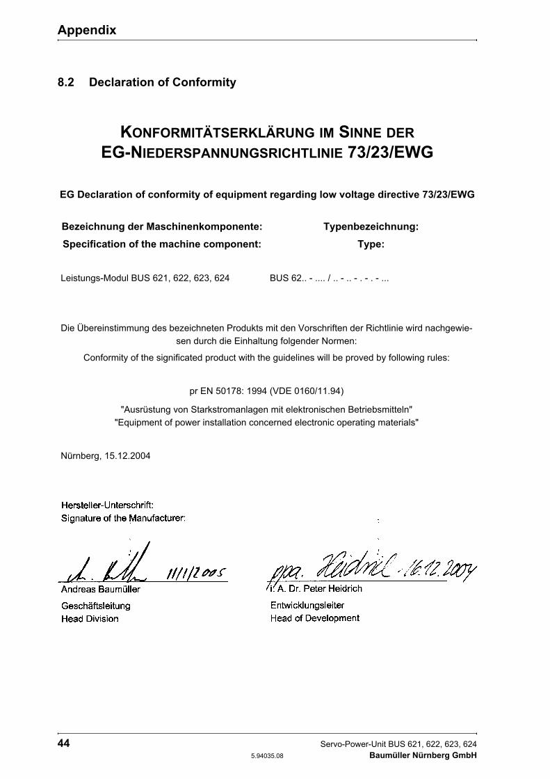
8.2 Declaration of Conformity
KONFORMITÄTSERKLÄRUNG IM SINNE DEREG-NIEDERSPANNUNGSRICHTLINIE 73/23/EWG
EG Declaration of conformity of equipment regarding low voltage directive 73/23/EWG
Bezeichnung der Maschinenkomponente: Typenbezeichnung:Specification of the machine component: Type:
Leistungs-Modul BUS 621, 622, 623, 624 BUS 62.. - .... / .. - .. - . - . - ...
Die Übereinstimmung des bezeichneten Produkts mit den Vorschriften der Richtlinie wird nachgewie-sen durch die Einhaltung folgender Normen:
Conformity of the significated product with the guidelines will be proved by following rules:
pr EN 50178: 1994 (VDE 0160/11.94)
"Ausrüstung von Starkstromanlagen mit elektronischen Betriebsmitteln""Equipment of power installation concerned electronic operating materials"
Nürnberg, 15.12.2004
Appendix
Servo-Power-Unit BUS 621, 622, 623, 624 45 Baumüller Nürnberg GmbH 5.94035.08

Appendix
46 Servo-Power-Unit BUS 621, 622, 623, 624 5.94035.08 Baumüller Nürnberg GmbH
8.3 General Conditions of Sale and Delivery
1. Obligation and Conclusion of Contracta) Deliveries of goods and provision of services shall be
effected exclusively based on these trading conditions. They are an essential component of the contracts for delivery and shall be considered as having been accepted by the placing of an order. In the case of constant busi-ness relations, they also apply for the future contracts.
b) Agreements diverging from the contract and verbal collat-eral agreements shall only be binding if they have been confirmed in writing by Baumüller Nürnberg GmbH(herein-after referred to as Baumüller). Diverging trading condi-tions on the behalf of the purchaser shall be without obligation, even where these have not been expressly objected to. These General Conditions of Sale and Deliv-ery shall be considered as having been accepted by the purchaser at the latest when the delivery is accepted.
c) In as far as deliveries of goods are subject to separate external obligations in accordance with the Law Concern-ing Foreign Trade and Payments with respect to the Fed-eral Office for Economics, the purchaser has to observe the relevant conditions at his/her own responsibility.
2. Price and OffersOffers are subject to confirmation, not binding and apply subject to material supply possibilities. Supplements and amendments require written confirmation. Prices are ex works and are subject to confirmation. Invoicing takes place in accordance with the prices valid on the date of delivery.
3. Extent of Delivery and Delivery Timea) Specified delivery periods/dates are without obligation, in
as far as nothing else to the contrary has been expressly agreed upon in writing. Delivery periods do not commence until the purchaser has fulfilled all duties of co-operation, in particular regarding details of performance. In the event that the agreed deposits for orders are delayed, then the delivery time shall be extended accordingly.
b) The purchaser is entitled, in particular in the event of a delay in delivery of longer than 3 months, to set an appro-priate period of grace and after its expiry, to withdraw from the order. Claims to compensation due to non-fulfilment or delay shall be excluded, in as far as Baumüller is not responsible for intent or gross negligence.
c) Baumüller is entitled at any time to effect partial deliveries and partial services, as well as to invoice these accord-ingly.
4. Delivery Problemsa) Delays/preventions in the delivery of goods or the provi-
sion of services due to force majeure entitle Baumüller to delay the production and delivery by the duration of the obstruction plus an appropriate period of time or to with-draw in part or in whole from the order.
b) Industrial disputes or other circumstances which substanti-ally impede or render impossible the delivery, such as, in particular, disturbances in the operating processes, pro-blems in procuring materials, official directives also apply as force majeure, irrespective of whether they arise with regard to Baumüller or suppliers.
c) In these cases, Items 4 a), b), the purchaser shall have no claim to compensation due to non-fulfilment or delay of the delivery.
5. PackagingItems for sale and delivery items are packaged and trans-port insurance policies are taken out according to the
instructions of and at a cost to the purchaser. Upon demand, the packaging material has to be returned wit-hout delay, free of freight charges and expenses.
6. Dispatch and Passing of RiskDeliveries shall be made ex works. The dispatch shall be effected at a cost to and at the risk of the recipient of the service/the purchaser. The risk passes to the recipient of the delivery/purchaser as soon as the delivery items leave the works. This shall apply at the latest, from the transfer-ral of the delivery items to the person carrying out the transport, forwarding agent or carrier.
7. Warrantya) The period of warranty amounts to 12 months from the
day of dispatch.In the event that a delivery item is defective, Baumüller shall deliver an additional replacement or make a subse-quent improvement at its own choice. Multiple subsequent improvements are permissible. Other warranty claims on the behalf of the purchaser, in particular also due to direct or indirect consequential damage are excluded. The pre-condition for any warranty is the normal contractual use of the delivery items. In the event of the utilisation of war-ranty services, the motor, the replacement part or the device has to be sent in free of freight charges, packaging costs or customs duties after prior co-ordination with Baumüller. Baumüller is exempted from any warranty if the party ordering returns the goods complained about without prior co-ordination or contrary to agreement. War-ranty claims expire one month after rejection of a defect on which notice is given, in as far as the purchaser remains silent in this respect.
8. Notification of Defectsa) The purchaser shall examine the subject matter of the
contract and delivery items immediately and give notice of any defects without delay, however, no later than 7 days after receipt of the delivery. In case of non-obvious defects notice has to be given in writing without delay after their discovery, however, no later than 6 months from the point of delivery. In the event that the purchaser does not give notice of any defects in writing within this period of time, then the subject matter of the contract shall be considered as having been approved.
b) The purchaser shall allow Baumüller a suitable inspection of defects of which notice is given and shall place all nec-essary/requested technical information, in particular, inspection records and test reports at Baumüller's dis-posal. In the event that the purchaser fails to do so, then the delivery items shall be considered as not having been complained about and as being approved. In the event that the purchaser alters the delivery items, then he/she shall lose his/her warranty claims.
c) In the event of an established material defect or perfor-mance defect, Baumüller can eliminate the defect or sup-ply a replacement. The purchaser can demand rescission or a reduction after the expiry of an appropriately set period of grace. Further claims on the behalf of the pur-chaser, in particular to the reimbursement of dismantling costs or installation costs are excluded. The same applies to damages which do not affect the delivery item itself.
d) Natural wear and tear and damage which arises after the transferral of risk, in particular also due to incorrect or neg-ligent handling, excessive demands or other unsuitable use not in conformity with the contract are excluded from

Appendix
Servo-Power-Unit BUS 621, 622, 623, 624 47 Baumüller Nürnberg GmbH 5.94035.08
the warranty. The same applies in particular for defects which are attributable to atmospheric discharges, over-voltages and chemical influences.
e) If no case of warranty is in existence or in the event that this subsequently turns out to be the case, the purchaser shall remunerate the utilisation or the use of an item or of a right, as well as services provided and expenses to an appropriate amount. Baumüller is entitled to a right of con-trol as referred to in §§ 315 ff. BGB [German Civil Code].
9. LiabilityContractual or legal claims on the behalf of the purchaser against Baumüller are limited to intent and gross negli-gence. This does not apply in as far as claims from the ProdHaftG [Product Liability Act] have been enforced. Baumüller shall only be held liable to the amount of the damage foreseeable in accordance with the purpose of the contract. Material damage which exceeds the value of a delivery/service is not foreseeable in this sense. The lia-bility is limited in terms of amount to the remuneration con-tractually owed.
10. Paymentsa) Invoices are payable at the time agreed in the contract, at
the latest within 30 days after the invoice date, in cash and without deductions. The purchaser can only offset with claims which are final and absolute or undisputed. The same applies to the exercising of rights of retention.
b) In the event of a delay in payment on the behalf of the pur-chaser, interest to the rate of 4 % above the respective minimum lending rate of the German Federal Bank, how-ever at least 10 % has to be paid, without separate proof being required.
c) Failure to comply with the terms of payment or circum-stances which endanger the credit worthiness of the pur-chaser result in all claims immediately becoming due. In these cases, deliveries shall only be made against pay-ment in advance.
d) Cash payments, bank transfers or cheque and bill pay-ments shall not be considered as payment/fulfilment of the obligation before the amount due for payment has been irrevocably received by Baumüller or credited to Baumüller's account.
e) Payments have to be made directly to Baumüller. The field staff are not entitled to accept payments or to issue exten-sions or waivers without separate written authority.
11. Reservation of Ownershipa) The ownership of delivery items remains reserved up to
the fulfilment of all existing claims against the purchaser from the business relation. Any bundling with other items shall be effected by the purchaser for Baumüller. Then, the entire product shall be considered as reserved goods.
b) The purchaser is entitled to sell the reserved goods in orderly business transactions. All claims to which the pur-chaser is entitled from this sale or other legal grounds shall be assigned by him/her in advance to Baumüller. Baumüller shall accept the assignment. In the event that the reserved goods are bundled or sold with other items standing in the possession of third parties, then the assignment shall only apply to the amount of the invoice value of the reserved goods. The purchaser is authorised to collect these assigned claims. Upon request, he/she has to make notice of the assignment to the debtor.
c) The purchaser shall inform Baumüller without delay of impending and enforced access on the behalf of third par-ties to the reserved goods or to the assigned claims. The purchaser shall bear the costs incurred by this.
d) The authorisation on the behalf of the purchaser to dis-pose of the reserved goods and to collect assigned claims expires in the event that the terms of payment are not complied with, in particular, also in the case of bill and cheque protests. In this case, Baumüller is entitled to take possession of the reserved goods. The purchaser bears the costs incurred by this. The taking back of goods shall only represent a withdrawal from the contract when this is expressly stated.
e) In the event that the value of the securities granted exceeds the secured claims in terms of amount by more than 20 %, then Baumüller shall renounce the securities exceeding this value.
12. Drawings and DocumentationBaumüller is entitled to the exclusive property right and copyright to cost estimates, drawings and all other docu-mentation. These documents may not be made accessible to third parties without prior written consent. In the event that a contract is not concluded, not implemented or other-wise ended, then all documents have to be returned immediately and unsolicited. There shall be no right to retention to these documents.
13. Copyright (in particular Software / Licence)a) Baumüller is exclusively entitled to all rights to the soft-
ware/edited versions, in particular property rights and copyrights to the relinquished software, in particular for the controlling of machines, systems and installations.
b) Baumüller grants the purchaser/buyer the non-exclusive, non-transferable right to use the relinquished software in the framework of the contractual purpose at the contractu-ally intended location/on the places in existence at the time of purchase (single licence). The software shall only be used on the associated purchased contractual item. Any use extending beyond this is prohibited. In the event of a use extending beyond this, Baumüller shall have the rights referred to in Items 13 c), 13 d).
c) It is prohibited to make copies of the relinquished soft-ware, whether in whole or in part, in as far as the making of copies of the machine-readable material in the frame-work of the required data backup or as copies for internal company use has not separately been agreed upon with prior written consent from Baumüller. Processing of the relinquished software, in particular by means of alteration, translation or by bundling with other programs shall only be permitted after prior written consent from Baumüller. Protection notices from Baumüller on/in the software may not be removed and also have to be adopted onto copies and edited versions. Copies produced contrary to this con-dition shall come under the possession and copyright of Baumüller. Baumüller can prohibit the use of such copies and elect to demand the immediate surrender or complete destruction with proof of this destruction.
d) The buyer is not permitted to extend the licence in terms of location/work places/machines/machine types or to grant rights of utilisation or grant sub-licences. The extension of the licence shall be permitted by Baumüller exclusively against a separate remuneration which has to be agreed upon in writing.
14. Applicable LawThe law of the Federal Republic of Germany is authorita-tive for all rights and obligations from and in connection with this contract. The regulations of the UN Sales Con-vention (CISG) are excluded.
15. Place of Performance and Place of JurisdictionThe place of performance for delivery and payment is the seat of Baumüller. The place of jurisdiction for all dispu-
Appendix
48 Servo-Power-Unit BUS 621, 622, 623, 624 5.94035.08 Baumüller Nürnberg GmbH
putes from and in connection with this contract, in particu-lar also for cheque and bill liabilities is the seat of Baumüller.
16. MiscellaneousIn the event that individual or several conditions of these Conditions of Sale and Delivery should be or become inef-fective in part or in whole, then the validity of the remain-ing conditions shall remain unaffected by this. The parties shall complement/replace the ineffective or incomplete condition with an appropriate regulation which most exten-sively corresponds to the economic purpose of the con-tractually desired regulation. The same applies for the case of the presence of a gap in the regulations.For the case that acceptance and installation are also agreed upon, then the following conditions, Items 17 and 18 shall also apply:
17. Acceptancea) The inspection of the delivery items ready for acceptance
shall take place in the Baumüller works. The purchaser shall bear the costs of this inspection. In the event that the purchaser fails to perform the inspection, then the delivery items shall be considered as having been delivered in conformity with the contract when they leave the works.
b) The purchaser is obliged to take delivery of goods and services from Baumüller without delay. Immaterial defects do not entitle the purchaser to refuse the acceptance.
c) In the event that the purchaser does not declare within 7 days after notification of the readiness for acceptance on the behalf of Baumüller or after receipt of the contractual service in writing and with exact, examinable specification of reasons that he/she refuses the acceptance, then the acceptance shall be considered as having been declared and the orderly performance of the contract as having been ascertained.
d) The agreed service shall be considered as having been accepted when the item delivered has been put into oper-ation by the purchaser himself/herself or upon his/her instructions by third parties beyond the functional test re-
quired to carry out the acceptance. This also applies in the event that the purchaser refuses the functional test/the acceptance without sufficient cause.
e) Experts to be designated by both parties shall take part in the acceptance inspection. The result of the functional test shall be entered in a record to be signed by the purchaser in consideration of the technical specifications.
18. Erection and InstallationErection and installation shall only be effected in the case of express agreement at the following further conditions:
a) The purchaser makes required workers and material avail-able at his/her own expense.
b) Before the commencement of installation works the pur-chaser shall make available unsolicited all required speci-fications, in particular concerning the location of power lines which have been laid such that they are hidden and similar installations, as well as the required static specifi-cations.
c) Before the commencement of the erection/installation, the delivery items required for the commencement of works have to be on site and all preliminary works progressed to the extent that the erection/installation can immediately begin and be completely carried out without interruption.
d) In the event that the erection, installation or putting into operation is delayed due to circumstances for which Baumüller is not responsible, then the purchaser shall bear the costs for idle time and journeys required on the behalf of the installation personnel.
e) The installation personnel working time has to be certified weekly by the purchaser. The purchaser shall present to the installation personnel a written certification regarding the ending of the erection/installation without delay.
f) Baumüller shall not be held liable for the installation per-sonnel works, in as far as the works are not connected to the delivery and the erection or installation.
g) Trial runs on systems not supplied by Baumüller shall not be carried out by the installation personnel.

Appendix
Servo-Power-Unit BUS 621, 622, 623, 624 49 Baumüller Nürnberg GmbH 5.94035.08

Appendix
50 Servo-Power-Unit BUS 621, 622, 623, 624 5.94035.08 Baumüller Nürnberg GmbH
8.4 Index
AAssembly 17Assembly notes 19Attachment 20
BBlock diagram 11
CCommisioning 33Coolant temperature range 12
DDC link capacitor 12DC link voltage 12Declaration of conformity 44Dimensions 18Disposal 41
EElectrical data 12EMC notes 21EMC package 32Environmental conditions 40
FFunction description 10
GGeneral conditions of sale and delivery 46
IInstallation 21
LLow voltage supply 12
MMaintenance 39Maintenance notes 39Max. current 12Messages 36Motor max. power 12
NNominal current 12
OOutput voltage 12
PPollution degree 17Power reduction 12
RRecommissioning 40
SSafe stop 22Safety categories 23Safety notes 5
Safety relay 23
TTechnical data 9, 22Terminal diagram 28Terminal notes 29Terminal strip X99A/X99B 31Type code 13Typical motor power 12
UUnexpected ramp-up 22Unpacking 15
XX60 32X68 32
ZZK+, ZK- 30


Baumüller Nürnberg GmbH Ostendstraße 80-90 90482 Nürnberg T: +49(0)911-5432-0 F: +49(0)911-5432-130 www.baumueller.de
All information given in this manual is customer information, subject to change without notice. We reserve the right to futher develop and actualize our products continuously using our permanent revision service. Please notice, that specifications/data/information are current values according to the printing date.These statements are not legally binding according to the measurement, computation and calculations. Before you make any information given in this manual to the basis of your own calculations and/or applications, please make sure that you have the latest edition of the information in hand.No liability can be accepted concerning the correctness of the information.