Embed Size (px)
Citation preview
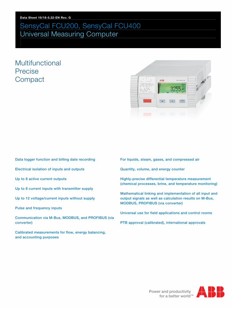
Data Sheet 10/18-5.22-EN Rev. G
SensyCal FCU200, SensyCal FCU400 Universal Measuring Computer
Multifunctional Precise Compact
Data logger function and billing date recording Electrical isolation of inputs and outputs Up to 8 active current outputs Up to 8 current inputs with transmitter supply Up to 12 voltage/current inputs without supply Pulse and frequency inputs Communication via M-Bus, MODBUS, and PROFIBUS (via converter) Calibrated measurements for flow, energy balancing, and accounting purposes
For liquids, steam, gases, and compressed air Quantity, volume, and energy counter Highly-precise differential temperature measurement (chemical processes, brine, and temperature monitoring) Mathematical linking and implementation of all input and output signals as well as calculation results on M-Bus, MODBUS, PROFIBUS (via converter) Universal use for field applications and control rooms PTB approval (calibrated), international approvals
Change from one to two columns

SensyCal FCU200, SensyCal FCU400 Universal Measuring Computer
2 10/18-5.22-EN | FCU200-T, FCU200-W, FCU400-G, FCU400-IR, FCU400-P, FCU400-S (SensyCal)
General description
The FCU is a universal measurement computer that supports a whole host of process signal processing applications. It combines the very latest communication methods with many years of expertise in the field of measurement technology. All physical and electrical process variables, as well as device data, data logger data, and billing dates, can be displayed on a high-resolution, multi-line LCD display. The following device models are available: Type Function
FCU200-W Heat quantity, cold quantity computer for water and brine
FCU400-S Steam, saturated steam computer (flow, heat)
FCU400-G Gas flow computer, gas translator
FCU200-T Current-pulse converter
FCU400-P Signal combination, highly-precise ΔT measurement,
totalizing, etc.
FCU400-IR Contactless temperature monitoring
SensyCal FCU200-W – Heat quantity computer Description The FCU200-W is a heat quantity computer for determining industrial thermal balances. It is used for calculating heat, cold, and flow quantities in liquids, within district heating supplies, and for calibrated measurement for accounting purposes. Reliable microelectronics, developed in line with standards DIN EN ISO 1434-1 ... 6 and OIML75. The heat quantity computer can be used in conjunction with all standard flowmeters that provide a pulse signal (including a NAMUR-compliant one), frequency signal, or mA signal, such as orifices, ultrasound flowmeters, swirl flowmeters, or vortex flowmeters. Connecting Pt100 temperature sensors in a four-wire circuit enables precise temperature measurement. Microprocessor technology and the integrated data logger allow for reliable, traceable acquisition of operating values.
Operating principle The heat quantity is calculated from the volume or mass flow and the temperatures of hot water Tw and cold water Tk at a given pressure level, using the formulae below.
p,Tqq vm
p,Thp,ThqP kkwwm
t
0
vdtqV
p,Thp,Thp,TVE kkww Element in formula Description
E Heat energy
V Volume
P Power
qv Volume flow
qm Mass flow
ρ Current operating density
hw Enthalpy in heat flow
hk Enthalpy in cold flow
Tw Hot water temperature
Tk Cold water temperature
p Pressure
Temperatures Tw and Tk are measured using Pt100 resistance thermometers.
FCU200-T, FCU200-W, FCU400-G, FCU400-IR, FCU400-P, FCU400-S (SensyCal) | 10/18-5.22-EN 3
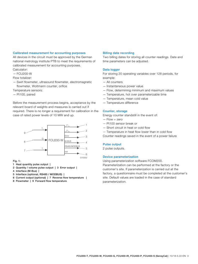
Calibrated measurement for accounting purposes All devices in the circuit must be approved by the German national metrology institute PTB to meet the requirements of calibrated measurement for accounting purposes. Calculator: — FCU200-W Flow totalizer: — Swirl flowmeter, ultrasound flowmeter, electromagnetic
flowmeter, Woltmann counter, orifice Temperature sensors: — Pt100, paired Before the measurement process begins, acceptance by the relevant board of weights and measures is carried out if required. There is no longer a requirement for calibration in the case of rated power levels of 10 MW and up.
G10032
FCU200-W
Tw
Tk
Q
Error
M-BUS
RS485/MODBUS
mA
1
2
3
4
5
6
9
8
7
Fig. 1: 1 Heat quantity pulse output | 2 Quantity / volume pulse output | 3 Error output | 4 Interface (M-Bus) | 5 Interface (optional, RS485 / MODBUS) | 6 Current output (optional) | 7 Reverse flow temperature | 8 Flowmeter | 9 Forward flow temperature
Billing date recording Two billing dates for storing all counter readings. Date and time parameters can be adjusted. Data logger For storing 20 operating variables over 128 periods, for example: — All counters — Instantaneous power value — Flow, determining minimum and maximum values — Temperature, hot over parameterizable time — Temperature, mean cold value — Temperature difference Counter, storage Energy counter standstill in the event of: — Flow = zero — Pt100 sensor break or — Short circuit in heat or cold flow — Temperature in heat flow lower than in cold flow Counter readings saved in the event of a power failure Pulse output 2 pulse outputs. Device parameterization Using parameterization software FCOM200. Parameterization can be performed at the factory or the customer's site. If parameterization is carried out at the factory, a questionnaire must be completed at the customer's site. Default values are loaded in the case of standard parameterization.

SensyCal FCU200, SensyCal FCU400 Universal Measuring Computer
4 10/18-5.22-EN | FCU200-T, FCU200-W, FCU400-G, FCU400-IR, FCU400-P, FCU400-S (SensyCal)
SensyCal FCU400-S – Steam computer Description The FCU400-S is a steam, flow, and thermal output computer designed for industrial quantity measurements, thermal balances, and measurements for accounting purposes. It is used for superheated steam or saturated steam with or without condensate reverse flow, as a flowmeter and / or a heat quantity computer. The measurement computer can be used in conjunction with all standard flowmeters that provide a pulse signal (including a NAMUR-compliant one), frequency signal, or mA signal, such as orifices, ultrasound flowmeters, swirl flowmeters, or vortex flowmeters. The split-range procedure, flow coefficient correction, and expansion rate correction are possible in the standard program in the case of flow measurement involving orifices. With the standard program, process signals from the following measuring devices can be processed: — Flowmeters in steam forward flow — Pressure transmitters in steam forward flow — Temperature sensors (Pt100 or via transmitters) in steam
forward flow — Flowmeters in condensate reverse flow — Temperature sensors (Pt100 or via transmitters) in
condensate reverse flow Up to 5 counters are provided in the standard program. The following applications can be realized.
G10033Δ Δp / p /q /q1 2 V m T1
p1
1 2 3 4
Fig. 2: Steam: flow, thermal output calculation
G10034
p / q /qV m1 2p /Δ Δp1
T1p / q /qV m1 2p /Δ Δ
4
1 2 3
Fig. 3: Saturated steam: flow, thermal output calculation 1 Pressure transmitter | 2 Flowmeter | 3 Flow direction | 4 Temperature sensor
G10035
q /qV mp / p /1 2Δ Δ T1
T2
p1
1 2 3 4
5
63q /qV mp / p /1 2Δ Δ
Fig. 4: Forward flow: steam / saturated steam; reverse flow:
condensate 1 Pressure transmitter | 2 Forward flow | 3 Flowmeter (alternatively in condensate reverse flow) | 4 Temperature sensor (steam) | 5 Temperature sensor (condensate) | 6 Reverse flow
G10036
Δ Δp / q /q1 V mp /2 T1
T2
p1
q /qV m
1 2 3 4
567
Fig. 5: Open systems 1 Pressure transmitter | 2 Forward flow | 3 Flowmeter (steam) | 4 Temperature sensor (steam) | 5 Temperature sensor (condensate) | 6 Flowmeter (condensate) | 7 Reverse flow
The physical "density" and "enthalpy" values of steam and water are calculated in accordance with the latest version of industry standard IAPWS-IF 97. Connecting Pt100 temperature sensors in a four-wire circuit enables precise temperature measurement. Microprocessor technology and the integrated data logger allow for reliable, traceable acquisition of operating values.

FCU200-T, FCU200-W, FCU400-G, FCU400-IR, FCU400-P, FCU400-S (SensyCal) | 10/18-5.22-EN 5
Operating principle The mass flow is calculated from the volume flow and density. When the flow is measured by means of differential pressure measurement, the mass flow is corrected on the basis of the reference density, i.e. the operating density in relation to the density for which the measurement was designed. The heat quantity is calculated from the mass flow and enthalpy (internal energy of steam or water). In the case of steam and water, the density and enthalpy are a function of pressure and temperature. In the case of saturated steam, they are a function of pressure or temperature.
ddvm pTqq ,
dddm pThqP ,
t
PdtE0
For steam in the forward flow and condensate in the reverse flow, the following applies:
dddmSteam p,ThqP
Constp,ThqP wwwmCondensate
CondensateSteamBalance PPP Element in formula Description
E Heat energy
P Power
qv Volume flow
qm Mass flow
ρ Current operating density
hw Steam enthalpy
hk Condensate enthalpy
Tw Steam temperature
Tk Condensate temperature
p Pressure
Calibrated measurement for accounting purposes In Germany, there is no requirement for calibration in the case of measurement for accounting purposes involving steam. If requested by the customer, all the devices in the circuit may be supplied as calibrated devices in order to meet the requirements of calibrated measurement for accounting purposes. For this purpose, a request for special calibration for the FCU400-S measurement computer is submitted to the relevant board of weights and measures. Billing date recording Two billing dates for storing up to 5 counter readings. Date and time parameters can be adjusted. Data logger For storing up to 27 operating variables over 128 periods. — 5 counters (E1 energy (steam), M1 quantity (steam,
EΔ energy balance (steam condensate), E2 energy (condensate), M2 quantity (condensate))
— Instantaneous values of all process variables — Determining minimum and maximum values (over
parameterizable time) and mean values for 4 process variables (parameterizable)
Counter, storage Energy counter standstill in the event of: — Flow = zero Counter readings saved in the event of a power failure Pulse output 2 pulse outputs. Device parameterization Using parameterization software FCOM200. Parameterization can be performed at the factory or the customer's site. If parameterization is carried out at the factory, a questionnaire must be completed at the customer's site. Default values are loaded in the case of standard parameterization.

SensyCal FCU200, SensyCal FCU400 Universal Measuring Computer
6 10/18-5.22-EN | FCU200-T, FCU200-W, FCU400-G, FCU400-IR, FCU400-P, FCU400-S (SensyCal)
SensyCal FCU400-G – Gas flow computer, gas translator Description The FCU400-G is a gas flow computer and translator designed for industrial gas flow calculations and gas measurements for accounting purposes. The measurement computer can be used in conjunction with all standard flowmeters that provide a pulse signal (including a NAMUR-compliant one), frequency signal, or mA signal, such as orifices, ultrasound flowmeters, swirl flowmeters, or vortex flowmeters. The split-range procedure, compressibility factor, flow coefficient correction, and expansion rate correction are possible in the standard program in the case of flow measurement involving orifices. With the standard program, process signals from the following measuring devices can be processed: — Flowmeters — Pressure transmitters — Temperature sensors (Pt100 or via transmitters)
G10037
1 2 3 4
Fig. 6 1 Flowmeter | 2 Measurement computer | 3 Pressure transmitter | 4 Temperature sensor (Pt100 or via transmitter)
The physical compensation and conversion of the flow are calculated in accordance with EN ISO 5167-1 and VDI/VDO 2040.
Operating principle The standard volume flow is calculated from the volume flow, operating density, and standard density. The operating density can be calculated from the operating pressure, operating temperature, and standard density in the standard condition. When the flow is measured by means of differential pressure measurement, the standard volume flow is corrected on the basis of the reference density, i.e. the operating density in relation to the density for which the measurement was designed.
nvn QQ
ZZ
TT
pp nn
nn
In the case of differential pressure measurement:
A,A,C
CA/QQ measured,nn
Z,T,pf Element in formula Description
Qn Standard volume flow
Qv Operating volume flow
ρ Operating density
ρn Standard density
T Temperature
p Pressure
Z Compressibility factor
C Flow coefficient
ε Expansion rate
pn Pressure in standard condition (1.01325 bar)
Tn Temperature in standard condition (273.15 K)
Zn Flow coefficient in standard condition
A Design specifications for orifice

FCU200-T, FCU200-W, FCU400-G, FCU400-IR, FCU400-P, FCU400-S (SensyCal) | 10/18-5.22-EN 7
Billing date recording Two billing dates for storing counter readings. Date and time parameters can be adjusted. Data logger For storing up to 19 operating variables over 200 periods: — 1 counter — Instantaneous values of all process variables — Determining minimum and maximum values (over
parameterizable time) and mean values for 4 process variables (parameterizable).
Counter, storage Counter standstill in the event of: — Flow = zero Counter readings saved in the event of a power failure. Pulse output 2 pulse outputs. Device parameterization Using parameterization software FCOM200. Parameterization can be performed at the factory or the customer's site. If parameterization is carried out at the factory, a questionnaire must be completed at the customer's site. Default values are loaded in the case of standard parameterization.
SensyCal FCU200-T – Current-pulse converter Description The FCU200-T is a two-channel — energy, quantity, and volume counter — current-pulse converter — pulse-current converter Operating principle The device converts either direct current into a proportional pulse frequency or a proportional pulse frequency into direct current. With the standard program, the following process signals can be processed: — 2 active mA signals or 2 active pulse / frequency signals — 2 pulse output signals — Signals via M-Bus interface The mA output card, power supply card, and RS485 / RS232 card can be supplied as an option.

SensyCal FCU200, SensyCal FCU400 Universal Measuring Computer
8 10/18-5.22-EN | FCU200-T, FCU200-W, FCU400-G, FCU400-IR, FCU400-P, FCU400-S (SensyCal)
The following applications can be realized with the standard program:
G10032
FCU200-T
Error
M-BUS
RS485/MODBUS
1
2
3
4
5
7
6
FCU200-T
Error
M-BUS
RS485/MODBUS
mA
mA
mA
mA
Fig. 7 1 Pulse outputs | 2 Error output | 3 Interface (M-Bus) | 4 Interface (optional, RS485 / MODBUS) | 5 Current outputs (optional) | 6 Pulse inputs | 7 Current inputs
Device parameterization Using parameterization software FCOM200. Parameterization can be performed at the factory or the customer's site. If parameterization is carried out at the factory, a questionnaire must be completed at the customer's site. Default values are loaded in the case of standard parameterization. Pulse output 2 pulse outputs.
SensyCal FCU400-P – Signal combination, highly-precise ΔT measurement, totalizing, etc. Description Precise differential temperature measurement is a must wherever thermal balancing is required for additional process optimization. The FCU400-P is a system consisting of a measurement computer, which serves as an evaluation unit, and 2 high-quality, precise, paired, and carefully-selected Pt100 sensors. In the lower measuring range (ΔT = 1 ... 5 K), the system also offers a measuring error of < 100 mK. If required, it can be calibrated and certified at a German Calibration Service (DKD) calibration lab.
G10039
FCU400-P
T1
T2
Error
M-BUS
RS485/MODBUS
1
2
3
4
5
6
8
7
T (4 ... 20 mA)1
T (4 ... 20 mA)2
ΔT (4 ... 20 mA)
Fig. 8 1 Analog output T1 (optional) | 2 Analog output T2 (optional) | 3 Analog output ΔT (optional) | 4 Error output | 5 Interface (M-Bus) | 6 Interface (optional, RS485 / MODBUS) | 7 Input for temperature sensor T1 (forward flow) | 8 Input for temperature sensor T2 (reverse flow) |
Inputs 2 x Pt100 temperature sensors in four-wire circuit (Ex d / Ex i) Output M-Bus, optional analog outputs and RS485 / RS232 for MODBUS protocol. Additional applications (e.g., totalizing) and technical details for the FCU400-P available on request.

FCU200-T, FCU200-W, FCU400-G, FCU400-IR, FCU400-P, FCU400-S (SensyCal) | 10/18-5.22-EN 9
Billing date recording Two billing dates for storing counter readings. Date and time parameters can be adjusted. Data logger 1 or 2 counters. Storage of process variables over 200 periods; programmable time window: — Instantaneous values — Minimum and maximum values — Mean values Saving Counter readings saved in the event of a power failure. Pulse output 2 pulse outputs.
SensyCal FCU400-IR – Contactless temperature monitoring Description The FCU400-IR is a complete system for contactless temperature monitoring at contact points and circuit breakers on MV switchgear. Loose screw connections and oxidation at the contact points between the busbars and at the circuit breakers lead to an increase in contact resistance. This causes power to be converted into heat energy, which in turn damages the system.
G10040
FCU400-IR
1
2
3
Fig. 9 1 FCU400-IR | 2 Pyrometer | 3 Measuring points
Properties — Continuous temperature monitoring on live components — Monitoring of up to 12 hotspots in switchgear using one
system — Freely-adjustable limit values for the pre-alarm and main
alarm — Analog output for maximum temperature value (optional) — MODBUS output (optional) — No PVC cables — Full shielding of all components against electromagnetic
disturbances — Option of connecting a Pt100 temperature sensor for the
purpose of measuring the ambient temperature

SensyCal FCU200, SensyCal FCU400 Universal Measuring Computer
10 10/18-5.22-EN | FCU200-T, FCU200-W, FCU400-G, FCU400-IR, FCU400-P, FCU400-S (SensyCal)
— M-Bus and optical interfaces (IRDA, ZVEI) for reading out data and configuration
— All necessary parameters displayed on a multi-line LCD display on site
— All measuring points and maximum temperatures displayed with measuring point identification in each case
— Data logger function with real-time clock for all temperatures and limit values
— If a limit value is exceeded, the error is stored together with the date and time
— Minimum adjustment work on site, plus excellent upgradeability (modular structure)
How you can benefit from using the FCU400-IR: — Lower costs — No expensive routine checks of contact points required — No measuring system maintenance required — Improved system safety — No malfunctions thanks to fast online detection of hotspots
and shutdown of switchgear — Measuring system does not come into contact with live
components The system principally consists of the following components: — Infrared pyrometer for hotspot monitoring in the busbar
area — Pt100 temperature sensor (optional) for measuring the
ambient temperature in the busbar area — Measurement computer for signal processing, evaluation,
and display in secondary equipment area
Inputs Maximal 12 x pyrometer
1 x Pt100, measuring range
0 … 200 °C (32 392 °F)
Outputs 3 binary switching outputs (pre-
alarm, alarm, and device error)
1 MODBUS output (optional)
or alternatively 1 analog output (optional),
4 … 20 mA signal for maximum
pyrometer temperature
Optical resolution of sensors 10:1
Length of sensor-measurement
computer connecting cable
10 m (standard)
Response time of entire system < 1 s
Reproducibility of temperature
measurement
± 0.75 °C or ± 0.75 % of measured
value (the larger value in each case
applies)
Degree of protection IP 40
Power supply 24 V DC ± 5 %
Maximum power consumption 10 VA
Maximum ambient temperature Measurement computer: 55 °C
(131 °F)
Pyrometer: 70 °C (158 °F)
Additional technical details for the FCU400-IR available on request.
FCU200-T, FCU200-W, FCU400-G, FCU400-IR, FCU400-P, FCU400-S (SensyCal) | 10/18-5.22-EN 11
Technical Data
System structure The measurement computer consists of a basic device with four slots for extension modules. The basic device contains: — Power supply unit — LCD display with backlighting — Processing electronics — 2 analog inputs for Pt100 temperature sensors with
constant power source for four-wire circuit — 2 digital, electrically isolated inputs for pulse or frequency
signals; can also be used for logic signals for control purposes
— 3 digital, electrically isolated outputs for pulse output and error signaling
— M-Bus interface — Optical interface on front, which can also be operated in
accordance with the IRDA or ZVEI standard, depending on the parameterization.
The four slots are designed to accommodate extension modules. You have the option of combining the following modules: — Current input module with transmitter supply — Current output module with limit monitors — RS485 / RS232 module for MODBUS communication — Supply for transmitters in two-wire technology
Electrical connections Analog inputs 2 x Pt100 IEC, measuring range -200 … 850 °C, resolution 20 bits ≈ 0.0012 K Digital inputs EB1, EB2 2 x electrically isolated, 24 V passive (optocoupler), can be configured in acc. with DIN 19240 as: — Pulse input 0.001 s-1 ... 3,000 s-1 — Frequency input 0.001 Hz ... 10 kHz — Logic signal (hi / low) Digital outputs AB1, AB2, and Err 3 x open collector, passive. Electrically isolated via optocoupler. External supply In acc. with VDE 2188, Category 2
Maximum load 24 VDC (± 25 %), < 100 mA
Maximum insulation voltage 500 Vss (peak-to-peak)
Internal resistance Ri in conductive
state
< 20 Ω
Function AB1: Pulse output
AB2: Pulse output
Err: Error output
Communication interfaces Communication takes place via the M-Bus protocol in acc. with EN 1434-3, IEC 870-5. Optical interface on the front of
the device
Electrical interface via terminal
strip of device
Operating mode can be
parameterized, optical head (ZVEI)
standard in acc. with
IEC EN 61107
(300 ... 400 (9,600) baud).
— 2-wire M-Bus interface (300 ...
38,400 baud)
— RS232 / RS485
(300 ... 38,400 baud)
The device is parameterized using the communication software (M-Bus). Data (operating variables, data logger, etc.) is read out via M-Bus or MODBUS.

SensyCal FCU200, SensyCal FCU400 Universal Measuring Computer
12 10/18-5.22-EN | FCU200-T, FCU200-W, FCU400-G, FCU400-IR, FCU400-P, FCU400-S (SensyCal)
Power supply DC voltage 24 V DC ± 20 %
(FCU400-IR ± 5 %)
AC voltage
(not in the case of FCU400-IR)
24 V AC, 110 V AC, 230 V AC,
-15 ... +10 %, 48 ... 62 Hz
Power consumption
24 V AC
1 ... 10 VA depending on extension
115 V AC 2 ... 10 VA depending on extension
230 V AC 3 ... 10 VA depending on extension
Extension modules The extension modules are inserted in the slots on the basic device. Module designation Description
101
2 x current inputs
(EX1, EX2)
0 / 4 ... 20 mA, RE = 50 Ω;
resolution 16 bits ≈ 0.3 μA
max. permissible input current
40 mA, electrically isolated
2 x transmitter supplies (Us1, Us2) each 16 V, 25 mA, short circuit-
proof, electrically isolated
107
4 x voltage inputs
(EX1 … EX4)
0 ... 2,500 mV, RE > 1 MΩ,
resolution 16 bits, max. permissible
input voltage + 5 V
108
4 x current inputs
(EX1 … EX4)
0 / 4 ... 20 mA, RE = 50 Ω;
resolution 16 bits ≈ 0.3 μA
max. permissible input current
± 40 mA
102
2 x analog outputs
(AX1, AX2)
Signal range 0 / 4 ... 20 mA,
load max. 500 Ω,
open permitted, short circuit-proof
2 x limit monitors
(ABX1, ABX2)
Open collector, passive
Electrical isolation via optocoupler.
External supply VDE 2188,
Category 2.
Maximum load 24 V (+ 25 %), <
100 mA.
Max. insulation voltage 500 V
(peak-to-peak).
105
RS485 / RS232 card
For MODBUS communication
106
2 x transmitter supplies (Us1, Us2)
each 20 V, 25 mA, short circuit-
proof, electrically isolated
Characteristic values
Temperature inputs
Temperature measuring error 0.3 % of measuring range end
value
Measuring error for differential
temperature
3 … 20 K, < 1.0 % of measured
value
20 … 250 K, < 0.5 % of measured
value
Current inputs
Effect of ambient temperature < 0.01 %/K
Calibration error < 0.2 % of end value
Maximum linearity error < 0.005 % FSR
Accuracy class of calculator EN 1434-1 / OIML 75 Class 2
Ambient conditions Ambient temperature -5 … 55 °C
Storage temperature -25 … 70 °C
Climate class Ambient temperature class C
acc. to EN 1434-1
Relative humidity Checked in acc. with EN 1434-4,
IEC 62-2-30
Condensation Permissible
Degree of protection IP 65
IP 40 (only in the case of FC400-IR)
Shock resistance during operation
(at 20 °C)
in acc. with IEC 68-2-6 or 68-2-27
Vibration: 2 g / 10 ... 150 Hz
Shock: 30 g / 11 ms / 3 shocks

FCU200-T, FCU200-W, FCU400-G, FCU400-IR, FCU400-P, FCU400-S (SensyCal) | 10/18-5.22-EN 13
Electromagnetic compatibility (EMC) Interference immunity in acc. with EN 50082-2 (EN 6100-4-2, -3, -4, -5, 6); also in acc. with EN 1434-4 (Class C), RFI suppression in acc. with EN 50081-2 (EN 55011 Class A) Type of test Standard Testing
accuracy
Effect
Surge on power supply
(AC)
com
diff. EN 61000-4-5
2 kV
1 kV
No effect
No effect
Burst on supply lines EN 61000-4-4 2 kV < 0.2 %
Burst on signal lines EN 61000-4-4 1 kV < 0.2 %
Discharge of static
electricity (contact
discharge)
EN 61000-4-2 6 kV < 0.2 %
Radiated field
(80 … 1,000 MHz) EN 61000-4-3 10 V/m < 0.2 %
Cable-guided radiation
(150 kHz … 80 MHz) EN 61000-4-6 10 V
Requirements
met
Line interruptions and
fluctuations
EN 61000-4-
411 - -
RFI suppression Limit value class adhered to
Interference voltage on
supply line
EN 55022 A
Interference field strength EN 55022 B
Operation Display LCD display, 120 x 32 pixels, multi-line, with backlighting. Billing date recording Two billing dates can be determined for the purpose of storing all counter readings. The date and time parameters can be adjusted independently for each billing date. Data logger The integrated data logger features 128 or 200 slots and has a ring buffer design. The data logger stores the process variables (counter readings, instantaneous values, min. / max. and mean values). Depending on the application concerned, the number of operating variables and slots may vary. Error messages The measurement computer enables internal errors to be detected thanks to regular self-diagnostics. — Critical device errors; e.g., storage failure, process errors — Power supply failures; meter standstill. The 10 most recent process errors are stored and can be called up as plain text with a time stamp via the LCD display. Err error output Open collector, passive

SensyCal FCU200, SensyCal FCU400 Universal Measuring Computer
14 10/18-5.22-EN | FCU200-T, FCU200-W, FCU400-G, FCU400-IR, FCU400-P, FCU400-S (SensyCal)
Mounting dimensions
DIN rail mounting and wall mounting
Dimensions
(width x height x depth)
144 mm x 72 mm x 183 mm
(5.67 inch x 2.83 inch x 7.2 inch)
Housing material Polycarbonate
Weight Approx. 0.7 kg (1.54 lb)
Panel mounting
Dimensions
(width x height x depth)
144 mm x 72 mm x 117 mm
(5.67 inch x 2.83 inch x 4.61 inch)
Panel cutout
(width x height)
139 mm x 69 mm
(5.47 inch x 2.72 inch)
Housing material Polycarbonate
Weight Approx. 0.5 kg (1.1 lb)
Approvals and certifications
— VDE certification (electrical safety) — PTB approval for systems requiring calibration in acc. with
EN 1434, Annex 22 (FCU200-W - SensyCal® W) — CSA-NRTL-C approval — GOST approval (Russia) Parameterization software The PC parameterization software FCOM200 is used for setting parameters in standard applications. The PC parameterization software FCOM200 for special applications is used for parameterization in customer-specific applications. The software can be installed and used on standard PCs. Two options are available for the connection between the PC and measurement computer: — Via the infrared interface on the front
(with optical head) — Via the M-Bus interface (with M-Bus repeater)
G10041
FCU400-IR
FCU400-IR
RS
23
2
M-BUSIOIOI
IOIOI
1 2
3
5 4
Fig. 10: 1 Serial interface RS232 | 2 Optical head | 3 Measurement computer | 4 M-Bus connection (2-wire) | 5 M-Bus repeater
Note on communication: The following settings must match on the PC and on the device (under "Device data"): Bus address, baud rate, interface. Interface Setting
With optical head Optical head / automatic
With M-Bus repeater M-Bus repeater
Infrared printer You can use the infrared interface to print out measurement computer data on the HP82240B portable mobile printer.

FCU200-T, FCU200-W, FCU400-G, FCU400-IR, FCU400-P, FCU400-S (SensyCal) | 10/18-5.22-EN 15
Change from two to one column
Electrical connections
Basic device
G10044
L N
1 5 6 2 3 7 8 4 10 11 50 51 16 17 18 19 52 53 24 25
EB1 EB2 AB1 AB2 ERR M-Bus
T1 T2
26 27
60 70 80 90
61 71 81 91
62 72 82 92
63 73 83 93
64 74 84 94
65 75 85 95
66 76 86 96
67 77 87 97
28
+ - + - + - + - + -
+ -
1 2 3 4
567891011
1213
Fig. 11 1 Slot 1 | 2 Slot 2 | 3 Slot 3 | 4 Slot 4 | 5 Power supply | 6 Interface (M-Bus) | 7 Error output | 8 Pulse output AB2 | 9 Pulse output AB1 | 10 Pulse / frequency input EB2 | 11 Pulse / frequency input EB1 | 12 Temperature sensor input T2 (Pt100) | 13 Temperature sensor input T1 (Pt100)

SensyCal FCU200, SensyCal FCU400 Universal Measuring Computer
16 10/18-5.22-EN | FCU200-T, FCU200-W, FCU400-G, FCU400-IR, FCU400-P, FCU400-S (SensyCal)
Supply and interface card (FCU200-W, FCU200-T, FCU400-S, FCU400-G, FCU400-P)
G10051
X0
X1
X2
X3
X4
X5
X6
X7
+ +
-
-
-+
EXX
+ +
-
-
-+
EXX
X0
X1
X2
X3
X4
X5
X6
X7
+
+
--
+EXX
+
-
-
A B
X0
X1
X2
X3
X4
X5
X6
X7
TxD (RS232)
GND (RS232)
RxD (RS232)
+B (RS485)
+Txd/Rxd (RS485)
-Txd/Rxd (RS485)
-B (RS485)
GND (RS485)
15
69
1
1
mA
mA
2 3
Fig. 12 A Power supply card | B Interface card RS232 / RS485 1 Transmitter in two-wire technology with current output | 2 Terminal strip for interfaces | 3 D-sub female connector, 9-pin
IMPORTANT (NOTE) A power supply card can supply either two transmitters with 20 V or one transmitter with 40 V (jumper between X3/X4). The X in the terminal designation of the extension cards must be replaced with 7, 8, or 9 (depending on the selected slot; see also "Electrical connections / Basic device").
FCU200-T, FCU200-W, FCU400-G, FCU400-IR, FCU400-P, FCU400-S (SensyCal) | 10/18-5.22-EN 17
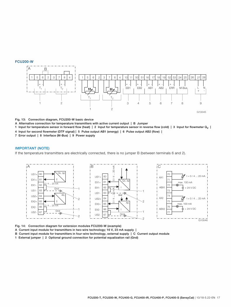
FCU200-W
G10045
L N
1 5 6 2 3 7 8 4 10 11 50 51 16 17 18 19 52 53 24 25
EB1 EB2 AB1 AB2 ERR M-Bus
26 27 28
+ - + - + - + - + -
+ -
1 5 6 2 3 7 8 4
+ - + -
B
T2T1
T2T1
21
A
9876543
21
Fig. 13: Connection diagram, FCU200-W basic device A Alternative connection for temperature transmitters with active current output | B Jumper 1 Input for temperature sensor in forward flow (heat) | 2 Input for temperature sensor in reverse flow (cold) | 3 Input for flowmeter Qv |
4 Input for second flowmeter (DTF signal) | 5 Pulse output AB1 (energy) | 6 Pulse output AB2 (flow) | 7 Error output | 8 Interface (M-Bus) | 9 Power supply
IMPORTANT (NOTE) If the temperature transmitters are electrically connected, there is no jumper B (between terminals 6 and 2).
G10046
US1+
EX1+
EX1-
US1-
US2+
EX2+
EX2-
US2-
60
61
62
63
64
65
66
67
I
0 / 4 ... 20 mA
Qv, p�
I
p� 2
0 / 4 ... 20 mA
Gnd
Gnd
US1+
EX1+
EX1-
US1-
US2+
EX2+
EX2-
US2-
60
61
62
63
64
65
66
67
I
Qv, p�
Gnd
0 /
4 ... 2
0 m
A
I
�p2
0 /
4 .
.. 2
0 m
A
Gnd
+ 24 V DC
+ 24 V DC
I = 0 / 4 ... 20 mA
I = 0 / 4 ... 20 mA
max. 100 mA
max. 100 mA
ABX2
AX1
ABX1
AX2
70
71
72
73
74
75
76
77
A B C
1
2
1
2
1
2
1
2
Fig. 14: Connection diagram for extension modules FCU200-W (example) A Current input module for transmitters in two-wire technology; 16 V, 23 mA supply | B Current input module for transmitters in four-wire technology, external supply | C Current output module 1 External jumper | 2 Optional ground connection for potential equalization rail (Gnd)

SensyCal FCU200, SensyCal FCU400 Universal Measuring Computer
18 10/18-5.22-EN | FCU200-T, FCU200-W, FCU400-G, FCU400-IR, FCU400-P, FCU400-S (SensyCal)
FCU400-S
G10045
L N
1 5 6 2 3 7 8 4 10 11 50 51 16 17 18 19 52 53 24 25
EB1 EB2 AB1 AB2 ERR M-Bus
26 27 28
+ - + - + - + - + -
+ -
1 5 6 2 3 7 8 4
+ - + -
B
T2T1
T2T1
21
A
9876543
21
Fig. 15: Connection diagram, FCU400-S basic device A Alternative connection for temperature transmitters with active current output | B Jumper 1 Input for temperature sensor in steam forward flow | 2 Input for temperature sensor in condensate reverse flow | 3 Pulse / frequency input EB1 (flow) | 4 Pulse / frequency input EB2 (flow) | 5 Pulse output AB1 | 6 Pulse output AB2 | 7 Error output | 8 Interface (M-Bus) | 9 Power supply IMPORTANT (NOTE) If the temperature transmitters are electrically connected, there is no jumper B (between terminals 6 and 2).
G10048
US1+
EX1+
EX1-
US1-
US2+
EX2+
EX2-
US2-
60
61
62
63
64
65
66
67
I
0 / 4 ... 20 mA
q , p1 1�
I
p
0 / 4 ... 20 mA
Gnd
Gnd
US1+
EX1+
EX1-
US1-
US2+
EX2+
EX2-
US2-
60
61
62
63
64
65
66
67
I
q , p1 1�
Gnd
0 /
4 .
.. 2
0 m
A
I
p0 /
4 ... 2
0 m
A
Gnd
+ 24 V DC
+ 24 V DC
I = 0 / 4 ... 20 mA
I = 0 / 4 ... 20 mA
max. 100 mA
max. 100 mA
ABX2
AX1
ABX1
AX2
70
71
72
73
74
75
76
77
A B C
1
2
1
2
1
2
1
2
Fig. 16: Connection diagram for FCU400-S extension modules (pressure and flow transmitters) A Current input module for transmitters in two-wire technology; 16 V, 23 mA supply | B Current input module for transmitters in four-wire technology, external supply | C Current output module 1 External jumper | 2 Optional ground connection for potential equalization rail (Gnd)

FCU200-T, FCU200-W, FCU400-G, FCU400-IR, FCU400-P, FCU400-S (SensyCal) | 10/18-5.22-EN 19
G10047
US1+
EX1+
EX1-
US1-
US2+
EX2+
EX2-
US2-
70
71
72
73
74
75
76
77
I
0 / 4 ... 20 mA
�p2
I q2
0 / 4 ... 20 mA
Gnd
Gnd
US1+
EX1+
EX1-
US1-
US2+
EX2+
EX2-
US2-
70
71
72
73
74
75
76
77
I
Gnd
0 /
4 .
.. 2
0 m
A
I
0 /
4 ... 2
0 m
A
Gnd
A B
1
2
1
2
1
2
1
2
�p2
Fig. 17: Connection diagram for FCU400-S extension modules (Δp2, condensate flow) A Current input module for transmitters in two-wire technology; 16 V, 23 mA supply | B Current input module for transmitters in four-wire technology, external supply | C Current output module 1 External jumper | 2 Optional ground connection for potential equalization rail (Gnd)

SensyCal FCU200, SensyCal FCU400 Universal Measuring Computer
20 10/18-5.22-EN | FCU200-T, FCU200-W, FCU400-G, FCU400-IR, FCU400-P, FCU400-S (SensyCal)
FCU400-G
G10049
L N
1 5 6 2 3 7 8 4 10 11 50 51 16 17 18 19 52 53 24 25
EB1 EB2 AB1 AB2 ERR M-Bus
26 27 28
+ - + - + - + - + -
+ -
1 5 6 2 3 7 8 4
+ - + -
B
ρnT
T
1
A
9876543
21
+ -
q1
Fig. 18: Connection diagram, FCU400-G basic device A Alternative connection for temperature transmitters with active current output | B Jumper 1 Input for temperature sensor | 2 Transmitter input for standard gas density | 3 Pulse / frequency input EB1 (flow) | 4 Pulse / frequency input EB2 | 5 Pulse output AB1 | 6 Pulse output AB2 | 7 Error output | 8 Interface (M-Bus) | 9 Power supply
IMPORTANT (NOTE) If the temperature transmitters are electrically connected, there is no jumper B (between terminals 6 and 2).
FCU200T
G10050
9876543
L N
1 5 6 2 3 7 8 4 10 11 50 51 16 17 18 19 52 53 24 25
EB1 EB2 AB1 AB2 ERR M-Bus
26 27 28
+ - + - + - + - + -
+ -
B
+ -+ -
1 2
+ 24 V DC
+ 24 V DC
I = 0 / 4 ... 20 mA
I = 0 / 4 ... 20 mA
max. 100 mA
max. 100 mA
ABX2
AX1
ABX1
AX2
80
81
82
83
84
85
86
87
A
Fig. 19: Connection diagram, FCU200-T basic device A Current output module (optional) | B Jumper 1 Input 1 for transmitters with active current output | 2 Input 2 for transmitters with active current output | 3 Pulse / frequency input EB1 | 4 Pulse / frequency input EB2 | 5 Pulse output AB1 | 6 Pulse output AB2 | 7 Error output | 8 Interface (M-Bus) | 9 Power supply IMPORTANT (NOTE) If the temperature transmitters are electrically connected, there is no jumper B (between terminals 6 and 2).

FCU200-T, FCU200-W, FCU400-G, FCU400-IR, FCU400-P, FCU400-S (SensyCal) | 10/18-5.22-EN 21
Dimensions
Panel mounting
G10042
FCU200-T
72 (2.8
3)
69
(2
.72
)1
144 (5.67)
139 (5.47)1
72
(2
.83
)
113 (4.45)
max. 10 (0,394)
69
(2
.72
)1
Fig. 20: All dimensions in mm (inch)
1 Panel cutout

SensyCal FCU200, SensyCal FCU400 Universal Measuring Computer
22 10/18-5.22-EN | FCU200-T, FCU200-W, FCU400-G, FCU400-IR, FCU400-P, FCU400-S (SensyCal)
Wall mounting (35 mm top-hat rail)
G10042
183 (7.20)
69 (2.7
2)1
72 (2.8
3)
FCU200-T
72 (2.8
3)
69 (2.7
2)1
144 (5.67)
139 (5.47)1
Fig. 21: All dimensions in mm (inch)
1 Panel cutout

FCU200-T, FCU200-W, FCU400-G, FCU400-IR, FCU400-P, FCU400-S (SensyCal) | 10/18-5.22-EN 23
Ordering information
Main ordering information Base model
Universal Measurement Computer
V18022 XX X X X X
Application
FCU200-W (SensyCal W), caloric energy computer, standard, water, cooling water, brine, oil (Note: 1) 10
FCU200-W (SensyCal W), caloric energy computer, others (Note: 1) 19
FCU400-S (SensyCal S), steam / saturated steam, standard, thermal output / flow correction (Note: 1) 25
FCU400-S (SensyCal S), steam / saturated steam, standard, flow correction (Note: 1) 2A
FCU400-S (SensyCal S), steam / saturated steam, others (special applications) (Note: 1) 29
FCU400-G (SensyCal G), gas, standard, flow correction (Qv, p, T) (Note: 1) 3C
FCU400-G (SensyCal G), gas, standard, flow correction (Δp, p, T) (Note: 1) 3D
FCU400-G (SensyCal G), gas, others (special applications) (Note: 1) 39
FCU400-P (SensyCal P), process applications, summation and subtraction (max. 6 inputs) (Note: 2) 46
FCU400-P (SensyCal P), process applications, high-precision differential temperature measurement (Note: 2) 4B
FCU400-P (SensyCal P), process applications, others (Note: 2) 49
FCU200-T (SensyCal T), counting / accounting, current-to-pulse converter (Note: 3) 57
FCU200-T (SensyCal T), counting / accounting, pulse-to-current converter (Note: 3) 58
FCU200-T (SensyCal T), counting / accounting, others (Note: 3) 59
FCU400-IR (SensyCal IR), temperature monitoring, Infrared temperature monitoring
(IR temp. sensor available on request)
(Note: 4) 60
Power Supply
230 V AC 1
115 V AC 2
24 V AC / DC (Not with FCU400-IR) 3
24 V DC (Only with FCU400-IR) 3
Approvals
Without calibration 0
With certificate from Verification Office for FCU200-W (SensyCal W) 1
Special certificate for FCU400-S, FCU400-G (SensyCal S, SensyCal G) 2
Calibration for high-precision differential temperature measurement 4
Others (special applications) 9
Configuration
Without configuration 0
With customer-specific configuration 1
Housing
Housing for panel mounting and wall mounting, 144 mm x 72 mm (5.67 x 2.83 in.) (Note: 5) 0

SensyCal FCU200, SensyCal FCU400 Universal Measuring Computer
24 10/18-5.22-EN | FCU200-T, FCU200-W, FCU400-G, FCU400-IR, FCU400-P, FCU400-S (SensyCal)
Additional ordering information All required options have to be entered by adding a one-digit or two-digit code or codes after the main order number. XXX XXX XXX XXX
Optional Extension Module no. 1
2 x mA inputs and 2 x transmitter supplies (2 x 16 V, 25 mA) 101
2 x mA outputs and 2 x alarm contacts 102
RS 485 / RS 232 card for MODBUS communication 105
2 x transmitter supplies (2 x 20 V, 25 mA) 106
4 x mV inputs (special application) 107
4 x mA inputs (summation, special application) 108
Optional Extension Module no. 2
2 x mA inputs and 2 x transmitter supplies (2 x 16 V, 25 mA) 101
2 x mA outputs and 2 x alarm contacts 102
RS 485 / RS 232 card for MODBUS communication 105
2 x transmitter supplies (2 x 20 V, 25 mA) 106
4 x mV inputs (special application) 107
4 x mA inputs (summation, special application) 108
Optional Extension Module no. 3
2 x mA inputs and 2 x transmitter supplies (2 x 16 V, 25 mA) 101
2 x mA outputs and 2 x alarm contacts 102
RS 485 / RS 232 card for MODBUS communication 105
2 x transmitter supplies (2 x 20 V, 25 mA) 106
4 x mV inputs (special application) 107
4 x mA inputs (summation, special application) 108
Optional Extension Module no. 4
2 x mA inputs and 2 x transmitter supplies (2 x 16 V, 25 mA) 101
2 x mA outputs and 2 x alarm contacts 102
RS 485 / RS 232 card for MODBUS communication 105
2 x transmitter supplies (2 x 20 V, 25 mA) 106
4 x mV inputs (special application) 107
4 x mA inputs (summation, special application) 108
Note 1: Select code 101 for mA inputs and code 102 for mA outputs. Select code 106 for supply of passive pulse / frequency input or temperature transmitter Note 2: 2 inputs are available for mA signals. Select code 108 for more inputs. Select code 106 for power supply Note 3: 2 inputs are available for active mA or pulse / frequency signals. Select code 106 for supply of the signals Note 4: Only with Power Supply 24 V DC Note 5: 19 in. cartridge see accessories

FCU200-T, FCU200-W, FCU400-G, FCU400-IR, FCU400-P, FCU400-S (SensyCal) | 10/18-5.22-EN 25
Accessories Designation Order number
FCU RS 232 cable (SUB-D 1:1 9-pole socket / plug), length 3 m, for M-Bus level transformer 7962895
FCU PC configuration program FCOM200, for FCU200-W, FCU400-S, FCU400-G, FCU200-T 7962875
FCU Optohead for connection to a PC via USB-Interface 7962897
FCU Optohead, for connection to a PC via RS 232 interface 7962876
FCU M-Bus micro-master with laptop adapter cable via RS 232 interface, for 10 terminal units (MR 003) 7962877
FCU M-Bus level transformer with RS 232 C interface for 3 terminal units, housing for Z rails or wall mounting PW3 7962878
FCU M-Bus level transformer with RS 232 C interface for 20 terminal units, housing for Z rails or wall mounting PW20 7962879
FCU M-Bus level transformer with RS 232 C interface for 60 terminal units, housing for Z rails or wall mounting PW60 7962880
FCU M-Bus level transformer with RS 232 C interface for 250 terminal units, housing for Z rails or wall mounting PW250 7962891
FCU Handheld printer for infrared communication 7962882
FCU Extension module 2 x mA inputs and 2 x transmitter supplies (2 x 16 V, 25 mA) 7962870
FCU Extension module 2 x mA outputs and 2 x alarm contacts 7962871
FCU Extension module RS 485 / RS 232 card for MODBUS communication 7962874
FCU Extension module 2 x transmitter supplies (2 x 20 V, 25 mA) 7962869
FCU Extension module 4 x mV inputs (special application) 7962881
FCU Extension module 4 x mA inputs (special application) 7962868
FCU400-IR Infra-red Thermometer (Sensytherm IR-CS), Temperature Range 0 ... 250 °C, Spectral Sensitivity 8 ... 14 μm, Optical
Resolution 10:1, Response Time 200 ms, Measurement Deviation 1.5 % of Reading, Power Supply 12 ... 28 V DC,
Connecting Cable 10 m
7962997
FCU400-IR Accessory for SensyCal IR with Sensytherm, protection housing against electromagnetic interferences 7962998
FCU Front Plate 19 in. Cover for SensyCal 7962896

SensyCal FCU200, SensyCal FCU400 Universal Measuring Computer
26 10/18-5.22-EN | FCU200-T, FCU200-W, FCU400-G, FCU400-IR, FCU400-P, FCU400-S (SensyCal)
Parameterization questionnaire
FCU200-W
Technical contact person Person responsible
Tel. / Fax Tel. / Fax
Tag name (2 x 20 characters) Language
Flow transmitter inputs
Pulse Frequency mA
Pulse value F min [Hz] F max [Hz] 0 ... 20 mA 4 ... 20 mA
qv-max qv-min qv-max qv-min qv-max
Absolute pressure [bar] (operating pressure) Δp-min Δp-max
Flow sensor placed in Warm flow For Δp measurem.: Δp transm. Linear
Cold flow Root extracting
For differential pressure measurement (orifice, nozzle, venturi, pitot tube flow meter) please add calculation.
Temperature inputs Pt100 direct Transmitter 0 … 20 mA 4 ... 20 mA
Tw min Tw max Tc min Tc max
Pulse output 1 Pulse output 2
Pulse value Pulse value
Puls width [ms] Puls width [ms]
Outputs Outputs (select signal)(Specify physical measuring ranges with units.)
0 ... 20 mA 4 ... 20 mA (for all outputs)
A1 A2 A3 A4
Physical value, start value
Physical value, final value

FCU200-T, FCU200-W, FCU400-G, FCU400-IR, FCU400-P, FCU400-S (SensyCal) | 10/18-5.22-EN 27
FCU400-S
Technical contact person Person responsible
Tel. / Fax Tel. / Fax
Tag name (2 x 20 characters) Language
Flow transmitter inputs for steam flow
Pulse Frequency mA
Pulse value F min [Hz] F max [Hz] 0 ... 20 mA 4 ... 20 mA
qv-max qv-min qv-max qv-min qv-max
For Δp measur.: Δp transm. Linear Root extracting Δp-min Δp-max
For differential pressure measurement (orifice, nozzle, venturi, pitot tube flow meter) please add calculation.
Flow transmitter inputs for condensate flow
Pulse Frequency mA
Pulse F min [Hz] F max [Hz] 0 ... 20 mA 4 ... 20 mA
qv-max qv-max qv-min qv-max
Absolute pressure (bar) (Operating pressure in the condensate)
Pressure transmitter Steam temperature Condensate temperature
0 ... 20 mA 4 ... 20 mA 0 ... 20 mA 4 ... 20 mA 0 ... 20 mA 4 ... 20 mA
Over / Abs. Pt100 direct Pt100 direct
bar / MPA °C °C
Pulse output 1 Pulse output 2 Counter
Counter Counter 3 Energy (steam condensate)
Pulse value Pulse value 1 Energy steam
Pulse width (ms) Pulse width (ms) 2 Mass steam
4 Energy condensate
5 Mass condensate
Outputs (standard: 2 outputs) Outputs (select signal )(Specify physical measuring ranges with units.)
0 ... 20 mA 4 ... 20 mA (for all outputs)
A1 A2 A3 A4
Physical value, start value
Physical value, final value
Zero point suppression for flow t/h
(applicable for calculating the flow, power, mass, volume, energy)
m3/h kg/h

SensyCal FCU200, SensyCal FCU400 Universal Measuring Computer
28 10/18-5.22-EN | FCU200-T, FCU200-W, FCU400-G, FCU400-IR, FCU400-P, FCU400-S (SensyCal)
FCU400-G
Technical contact person Person responsible
Tel. / Fax Tel. / Fax
Tag name (2 x 20 characters) Language
Flow transmitter inputs
Pulse Frequency mA
Pulse value F min [Hz] F max [Hz] 0 ... 20 mA 4 ... 20 mA
qv-max qv-min qv-max qv-min qv-max
Δp-min Δp-max
For Δp measur.: Δp transm. Linear Root extracting
For differential pressure measurement (orifice, nozzle, venturi, pitot tube flow meter) please add calculation.
Pressure transmitter Gas temperature
0 ... 20 mA 4 ... 20 mA 0 ... 20 mA 4 ... 20 mA
Over / Abs. Pt100 direct
bar / MPA °C
Pulse output 1 Counter
Counter 1 Nm3
Pulse value
Pulse width (ms)
Outputs (optional) Outputs (select signal )(Specify physical measuring ranges with units.)
0 ... 20 mA 4 ... 20 mA (for all outputs)
A1 A2 A3 A4
Physical value, start value
Physical value, final value

FCU200-T, FCU200-W, FCU400-G, FCU400-IR, FCU400-P, FCU400-S (SensyCal) | 10/18-5.22-EN 29
FCU200-T
Technical contact person Person responsible
Tel. / Fax Tel. / Fax
Tag name (2 x 20 characters) Language
Inputs
Channel 1
Pulse 1 Frequency 1 mA, 1
Pulse value F min [Hz] F max [Hz] 0 ... 20 mA 4 ... 20 mA
Max. value Min. value Max. value Min. value Max. value
Channel 2
Pulse 2 Frequency 2 mA, 2
Pulse value F min [Hz] F max [Hz] 0 ... 20 mA 4 ... 20 mA
Max. value Min. value Max. value Min. value Max. value
Pulse output 1 Pulse output 2
Pulse value Pulse value
Pulse width (ms) Pulse width (ms)
Outputs (optional) Outputs (select signal )(Specify physical measuring ranges with units.)
0 ... 20 mA 4 ... 20 mA (for all outputs)
A1 A2 A3 A4
Physical value, start value
Physical value, final value
An extension board (Code No. 106 with 2 x 20 V supply) is available for power supply of the inputs (pulse, frequency or mA).


Contact us
10/1
8-5.
22-E
N R
ev. G
09.
2011
Note We reserve the right to make technical changes or modify the contents of this document without prior notice. With regard to purchase orders, the agreed particulars shall prevail. ABB does not accept any responsibility whatsoever for potential errors or possible lack of information in this document. We reserve all rights in this document and in the subject matter and illustrations contained therein. Any reproduction, disclosure to third parties or utilization of its contents - in whole or in parts – is forbidden without prior written consent of ABB. Copyright© 2011 ABB All rights reserved
3KXF800000R1001
ABB Ltd. Process Automation Oldends Lane, Stonehouse Gloucestershire, GL10 3TA UK Tel: +44 (0)1453 826661 Fax: +44 (0)1453 829671 ABB Inc. Process Automation 125 E. County Line Road Warminster PA 18974 USA Tel: +1 215 674 6000 Fax: +1 215 674 7183 ABB Automation Products GmbH Process Automation Dransfelder Str. 2 37079 Goettingen Germany Tel: +49 551 905-534 Fax: +49 551 905-555 www.abb.com