Embed Size (px)
Citation preview

Insert document title
Location | Date
ATSB Transport Safety Report[Insert Mode] Occurrence InvestigationXX-YYYY-####Final
Investigation
Data entry and navigational issues involving Airbus A330-343X 9M-XXM
Investigation
Sydney Airport, New South Wales | 10 March 2015
ATSB Transport Safety ReportAviation Occurrence InvestigationAO-2015-029Final – 7 September 2016
Released in accordance with section 25 of the Transport Safety Investigation Act 2003
Publishing information
Published by: Australian Transport Safety Bureau Postal address: PO Box 967, Civic Square ACT 2608 Office: 62 Northbourne Avenue Canberra, Australian Capital Territory 2601 Telephone: 1800 020 616, from overseas +61 2 6257 4150 (24 hours) Accident and incident notification: 1800 011 034 (24 hours) Facsimile: 02 6247 3117, from overseas +61 2 6247 3117 Email: [email protected] Internet: www.atsb.gov.au
© Commonwealth of Australia 2016
Ownership of intellectual property rights in this publication Unless otherwise noted, copyright (and any other intellectual property rights, if any) in this publication is owned by the Commonwealth of Australia.
Creative Commons licence With the exception of the Coat of Arms, ATSB logo, and photos and graphics in which a third party holds copyright, this publication is licensed under a Creative Commons Attribution 3.0 Australia licence.
Creative Commons Attribution 3.0 Australia Licence is a standard form license agreement that allows you to copy, distribute, transmit and adapt this publication provided that you attribute the work.
The ATSB’s preference is that you attribute this publication (and any material sourced from it) using the following wording: Source: Australian Transport Safety Bureau
Copyright in material obtained from other agencies, private individuals or organisations, belongs to those agencies, individuals or organisations. Where you want to use their material you will need to contact them directly. Addendum
Page Change Date
5 and 13 Minor typographical errors corrected 9-9-2016
Safety summary
What happened On 10 March 2015 Airbus A330, registered 9M-XXM and operated by Malaysian-based airline Air Asia X, was conducting a regular passenger service from Sydney, New South Wales to Kuala Lumpur, Malaysia. On departure from runway 16R the aircraft was observed by air traffic control to enter the departure flight path of the parallel runway 16L. Following advice from air traffic control, the flight crew identified a problem with the onboard navigation systems. Attempts to troubleshoot and rectify the problem resulted in further degradation of the navigation system, as well as to the aircraft’s flight guidance and flight control systems. The crew elected to discontinue the flight but were unable to return to Sydney as the weather had deteriorated in the Sydney area and the available systems limited the flight to approaches in visual conditions. The aircraft was instead radar vectored to Melbourne, Victoria and the flight completed in visual conditions.
What the ATSB found The ATSB found that when setting up the aircraft’s flight management and guidance system, the captain inadvertently entered the wrong longitudinal position of the aircraft. This adversely affected the onboard navigation systems however, despite a number of opportunities to identify and correct the error, it was not noticed until after the aircraft became airborne and started tracking in the wrong direction. The ATSB also found that the aircraft was not fitted with an upgraded flight management system that would have prevented the data entry error via either automated initialisation or automatic correction of manual errors.
The flight crew attempted to troubleshoot and rectify the situation while under heavy workload. Combined with limited guidance from the available checklists, this resulted in further errors by the flight crew in the diagnosis and actioning of flight deck switches.
Finally, the ATSB identified that effective monitoring and assistance by air traffic control reduced the risk to the occurrence aircraft and other aircraft in the area.
What's been done as a result In response to this occurrence the aircraft operator undertook safety action, including:
• the development of a training bulletin and package for its flight crews that emphasised the correct operation and alignment of the air data and inertial reference system
• sharing the lessons learnt from the operator’s internal investigation with all pilots and reviewing the recovery procedures to be undertaken in the form of a flight safety notice.
Safety message This occurrence highlights that even experienced flight crew are not immune from data entry errors. However, carrying out procedures and incorporating equipment upgrades recommended by aircraft manufacturers will assist in preventing or detecting such errors.
Additionally, the airborne management of this occurrence illustrates the importance of effective communication when dealing with an abnormal situation under high workload conditions. This is especially the case when there is limited guidance available to resolve the issue.
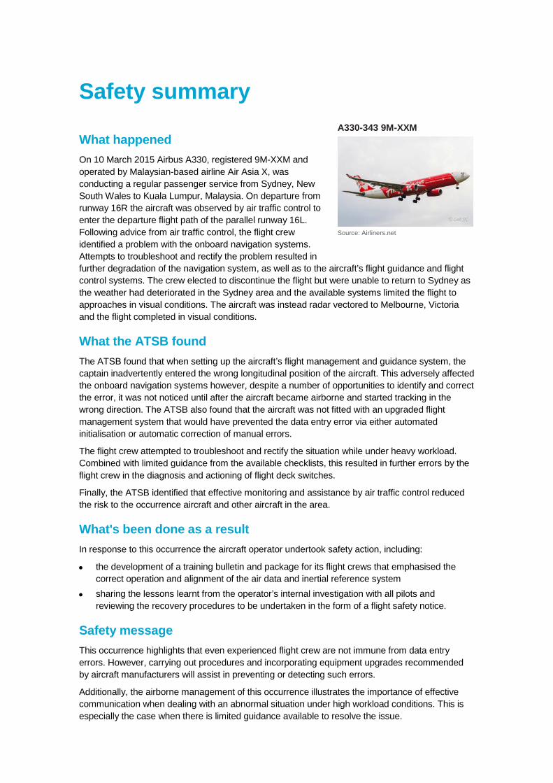
A330-343 9M-XXM
Source: Airliners.net

Contents The occurrence ........................................................................................................................1 Context ......................................................................................................................................9
Personnel information 9 Captain 9 First officer 9
Aircraft maintenance information 9 Maintenance status 9 Airbus service bulletin 9
Aircraft systems 10 Air data and inertial reference system 10
Procedural controls 14 Initialisation of the air data and inertial reference system 14 Electronic centralised aircraft monitoring 16
Flight control laws 18 Enhanced ground proximity warning system 18 Master warning during the go-around at Melbourne 18 Related occurrences 19
ATSB investigation 200700065 19 ATSB occurrence report 201104899 19 Global occurrences and action 19
Safety analysis ...................................................................................................................... 20 Introduction 20 Available upgrade to aircraft navigation systems 20 Development of the occurrence 20 Reliance on electronic centralised aircraft monitoring 26 Air traffic control support 26
Findings ................................................................................................................................. 27 Contributing factors 27 Other factors that increased risk 27 Other findings 27
General details ...................................................................................................................... 28 Occurrence details 28 Pilot details – Captain 28 Pilot details – First officer 28 Aircraft details 28
Sources and submissions .................................................................................................. 29 Sources of information 29 References 29 Submissions 29
Appendices ........................................................................................................................... 31 Appendix A – Standard instrument departure 31 Appendix B – Flight crew training manual extract 32
Australian Transport Safety Bureau .................................................................................. 34 Purpose of safety investigations 34 Developing safety action 34
› 1 ‹
ATSB – AO-2015-029
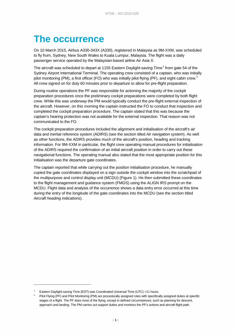
The occurrence On 10 March 2015, Airbus A330-343X (A330), registered in Malaysia as 9M-XXM, was scheduled to fly from, Sydney, New South Wales to Kuala Lumpur, Malaysia. The flight was a daily passenger service operated by the Malaysian-based airline Air Asia X.
The aircraft was scheduled to depart at 1155 Eastern Daylight-saving Time1 from gate 54 of the Sydney Airport International Terminal. The operating crew consisted of a captain, who was initially pilot monitoring (PM), a first officer (FO) who was initially pilot flying (PF), and eight cabin crew.2 All crew signed on for duty 60 minutes prior to departure to allow for pre-flight preparation.
During routine operations the PF was responsible for actioning the majority of the cockpit preparation procedures once the preliminary cockpit preparations were completed by both flight crew. While this was underway the PM would typically conduct the pre-flight external inspection of the aircraft. However, on this morning the captain instructed the FO to conduct that inspection and completed the cockpit preparation procedure. The captain stated that this was because the captain’s hearing protection was not available for the external inspection. That reason was not communicated to the FO.
The cockpit preparation procedures included the alignment and initialisation of the aircraft’s air data and inertial reference system (ADIRS) (see the section titled Air navigation system). As well as other functions, the ADIRS provides much of the aircraft’s position, heading and tracking information. For 9M-XXM in particular, the flight crew operating manual procedures for initialisation of the ADIRS required the confirmation of an initial aircraft position in order to carry out these navigational functions. The operating manual also stated that the most appropriate position for this initialisation was the departure gate coordinates.
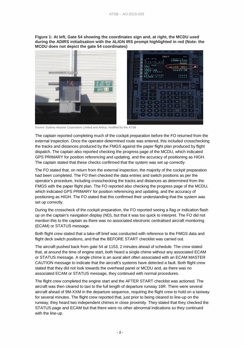
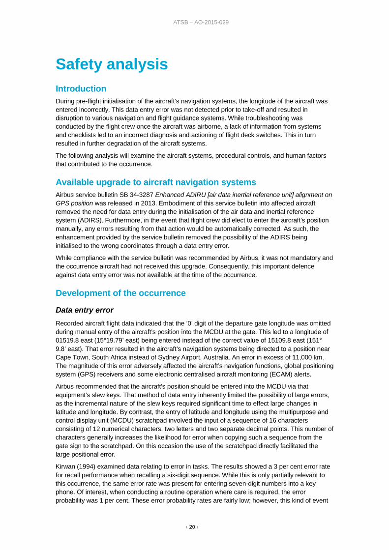
The captain reported that while carrying out the position initialisation procedure, he manually copied the gate coordinates displayed on a sign outside the cockpit window into the scratchpad of the multipurpose and control display unit (MCDU) (Figure 1). He then submitted these coordinates to the flight management and guidance system (FMGS) using the ALIGN IRS prompt on the MCDU. Flight data and analysis of the occurrence shows a data entry error occurred at this time during the entry of the longitude of the gate coordinates into the MCDU (see the section titled Aircraft heading indications).
1 Eastern Daylight-saving Time (EDT) was Coordinated Universal Time (UTC) +11 hours. 2 Pilot Flying (PF) and Pilot Monitoring (PM) are procedurally assigned roles with specifically assigned duties at specific
stages of a flight. The PF does most of the flying, except in defined circumstances; such as planning for descent, approach and landing. The PM carries out support duties and monitors the PF’s actions and aircraft flight path.
› 2 ‹
ATSB – AO-2015-029
Figure 1: At left, Gate 54 showing the coordinates sign and, at right, the MCDU used during the ADIRS initialisation with the ALIGN IRS prompt highlighted in red (Note: the MCDU does not depict the gate 54 coordinates)
Source: Sydney Airports Corporation Limited and Airbus, modified by the ATSB
The captain reported completing much of the cockpit preparation before the FO returned from the external inspection. Once the operator-determined route was entered, this included crosschecking the tracks and distances produced by the FMGS against the paper flight plan produced by flight dispatch. The captain also reported checking the progress page of the MCDU, which indicated GPS PRIMARY for position referencing and updating, and the accuracy of positioning as HIGH. The captain stated that these checks confirmed that the system was set up correctly.
The FO stated that, on return from the external inspection, the majority of the cockpit preparation had been completed. The FO then checked the data entries and switch positions as per the operator’s procedure, including crosschecking the tracks and distances as determined from the FMGS with the paper flight plan. The FO reported also checking the progress page of the MCDU, which indicated GPS PRIMARY for position referencing and updating, and the accuracy of positioning as HIGH. The FO stated that this confirmed their understanding that the system was set up correctly.
During the crosscheck of the cockpit preparation, the FO reported seeing a flag or indication flash up on the captain’s navigation display (ND), but that it was too quick to interpret. The FO did not mention this to the captain as there was no associated electronic centralised aircraft monitoring (ECAM) or STATUS message.
Both flight crew stated that a take-off brief was conducted with reference to the FMGS data and flight deck switch positions, and that the BEFORE START checklist was carried out.
The aircraft pushed back from gate 54 at 1153, 2 minutes ahead of schedule. The crew stated that, at around the time of engine start, both heard a single chime without any associated ECAM or STATUS message. A single chime is an aural alert often associated with an ECAM MASTER CAUTION message to indicate that the aircraft’s systems have detected a fault. Both flight crew stated that they did not look towards the overhead panel or MCDU and, as there was no associated ECAM or STATUS message, they continued with normal procedures.
The flight crew completed the engine start and the AFTER START checklist was actioned. The aircraft was then cleared to taxi to the full length of departure runway 16R. There were several aircraft ahead of 9M-XXM in the departure sequence, requiring the flight crew to hold on a taxiway for several minutes. The flight crew reported that, just prior to being cleared to line-up on the runway, they heard two independent chimes in close proximity. They stated that they checked the STATUS page and ECAM but that there were no other abnormal indications so they continued with the line-up.
› 3 ‹
ATSB – AO-2015-029
The FO commenced take-off from runway 16R with the captain monitoring take-off parameters and thrust settings. Immediately after the aircraft was rotated, the enhanced ground proximity system (EGPWS) activated with the aural alert TERRAIN, TERRAIN. This alert would normally indicate a conflict with the ground or obstacles in the aircraft’s immediate flight path. The next phase of the EGPWS is for automated aural and visual instruction on the flight crew’s NDs to PULL UP. Although both flight crew reported the expectation that this would occur, for reasons believed to be associated with spurious activation, this did not take place.
Flight crew are trained to conduct an EGPWS escape manoeuvre in response to the second phase warning by applying up to full back pressure on the control stick and the auto-throttle applies high levels of thrust to climb the aircraft away from any conflicting terrain in the shortest distance. The captain stated that, as it was daytime and 9M-XXM was clear of cloud, it was possible to visually confirm that no terrain conflict existed. As such, the captain instructed the FO to disregard the TERRAIN alert and continue with the normal take-off. Both crew stated that, while the alert had startled them, a full response to a spurious EGPWS warning was undesirable in the Sydney area due to an increased likelihood of conflicting with other aircraft.
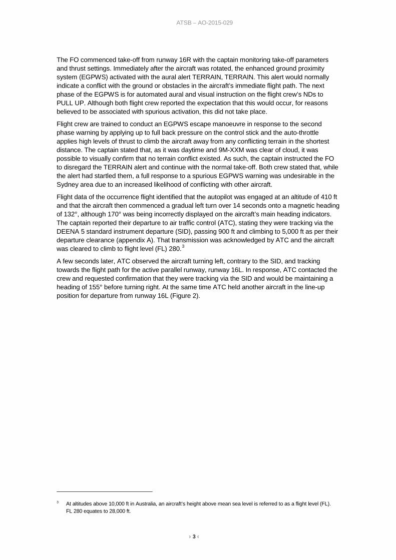
Flight data of the occurrence flight identified that the autopilot was engaged at an altitude of 410 ft and that the aircraft then commenced a gradual left turn over 14 seconds onto a magnetic heading of 132°, although 170° was being incorrectly displayed on the aircraft’s main heading indicators. The captain reported their departure to air traffic control (ATC), stating they were tracking via the DEENA 5 standard instrument departure (SID), passing 900 ft and climbing to 5,000 ft as per their departure clearance (appendix A). That transmission was acknowledged by ATC and the aircraft was cleared to climb to flight level (FL) 280.3
A few seconds later, ATC observed the aircraft turning left, contrary to the SID, and tracking towards the flight path for the active parallel runway, runway 16L. In response, ATC contacted the crew and requested confirmation that they were tracking via the SID and would be maintaining a heading of 155° before turning right. At the same time ATC held another aircraft in the line-up position for departure from runway 16L (Figure 2).
3 At altitudes above 10,000 ft in Australia, an aircraft’s height above mean sea level is referred to as a flight level (FL).
FL 280 equates to 28,000 ft.

› 4 ‹
ATSB – AO-2015-029
Figure 2: During departure 9M-XXM initially turned left, instead of right, and crossed the departure flight path of the parallel runway 16L (displayed here in blue). Note the standard instrument departure chart caution against turning left. The DEENA 5 SID is depicted in green
Source: Google earth, modified by the ATSB
ATC audio recordings indicated an initial hesitance in the captain’s reply to ATC, first confirming the heading and then asking ATC to standby as they had lost their primary instruments. During interviews the crew stated that once the EGPWS alert was assessed as spurious, and the decision not to carry out an EGPWS escape manoeuvre made, the crew noticed that all of the expected navigation waypoints and tracking information were not displayed on the ND. Instead, an amber GPS PRIMARY LOST message appeared on the NDs together with an unusual tracking line without an associated waypoint (Figure 3).
Figure 3: Photograph of an exemplar ND and the primary flight display during a simulated recreation of the flight scenario. Note the GPS PRIMARY LOST message (in yellow) at the bottom-left of the photograph and the green tracking line emanating from the white aircraft depiction at the centre of that representation
Source: Air Asia X
Following advice from the captain of the degraded flight display, ATC informed the flight crew that radar showed the aircraft was maintaining an approximate heading of 130°. The controller then instructed the flight crew to turn right onto a heading of 220° with reference to the main heading
› 5 ‹
ATSB – AO-2015-029
indicators. Once established on that heading, ATC requested the flight crew to report the heading displayed on the aircraft’s standby compass, to which the flight crew reported 180°. The controller confirmed that 180° matched the aircraft’s radar heading and used this heading offset to provide radar vectoring clear of other traffic in the Sydney area while also limiting the altitude of the aircraft to FL160 due to overflying conflicting traffic. The controller then requested the flight crew’s intentions, to which they replied that they would attempt to restore the aircraft’s systems before continuing on to Kuala Lumpur.
During interviews the flight crew stated that, following identification of the system problem, the captain adopted the role of PF with the autopilot engaged and managed the radio communication to allow the FO to troubleshoot the situation and attempt to restore normal system functionality. The captain advised that, as there were no ECAM or STATUS messages for guidance, the only instruction he gave the FO was to ‘Reset the nav’.
The FO stated that, in the absence of any ECAM or STATUS messages his initial reaction was to reference the UNRELIABLE AIRSPEED INDICATION checklist in the quick reference handbook (QRH). This was in order to provide the captain with attitude and thrust settings in the event that the airspeed indications were affected. This emergency checklist had been part of a recent training/checking exercise the crew had undergone in response to an occurrence involving another A330. In that occurrence, some of the aircraft’s external sensors had blocked with ice, which affected the air data reference (ADR), part of the ADIRS, and subsequently provided erroneous airspeed indications.
The FO recalled then reaching a mindset that there was an issue with the aircraft’s ADR. As part of the ADIRS, information from the ADR provided temperature, aerodynamic, and barometric information from multiple air data sources to much of the aircraft’s primary flight guidance, flight controls and engine controls. The ADR CHECK PROCEDURE is incorporated in the UNRELIABLE SPEED INDICATION checklist that was recently referenced by the FO.
The FO then attempted to program a waypoint and a radio navigation aid. Both were unsuccessful as the FMGS appeared unresponsive to inputs. The FO stated that the absence of an ECAM or STATUS indication hindered their ability to locate a checklist in the QRH that offered a resolution to the situation. As a result, the FO started searching the electronic FCOM on the company-provided iPad™. ATC continued to provide radar vectoring, climb and stop-climb instructions and request updates of the crew’s intentions.
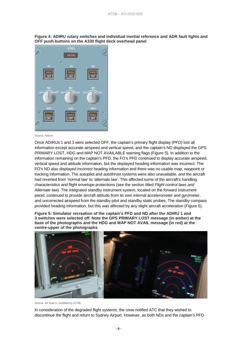
The FO informed the captain that, in order to attempt to reset the system, it was intended to cycle the three air data and inertial reference unit (ADIRU) rotary switches on the overhead panel from NAV to OFF (Figure 4), and that this would likely cause the autopilot to drop out. The ADIRU rotary switches influence both the ADR and inertial reference parts of the respective ADIRU, and have a greater combined effect on aircraft systems compared with the individual ADR and/or inertial reference push-buttons available on the same overhead panel (Figure 4) (see the section titled Context).
During interview the captain and FO stated that the captain’s response was simply ’Yes’. The FO recalled initially holding their hand in the vicinity of the rotary switches awaiting confirmation from the captain to cycle them to OFF. Both crew recalled that ATC instructions then disrupted the normal process of confirmation before actioning critical flight deck switches. Once the ATC instruction was acknowledged and complied with, the FO turned ADIRU 1 and 3 OFF without clarifying the captain’s confirmation for the action. In response, several flight guidance and navigation systems degraded and the autopilot disengaged. The captain instructed the FO to stop actioning the switches, with ADIRU 2 remaining in the NAV position.
› 6 ‹
ATSB – AO-2015-029
Figure 4: ADIRU rotary switches and individual inertial reference and ADR fault lights and OFF push-buttons on the A330 flight deck overhead panel
Source: Airbus
Once ADIRUs 1 and 3 were selected OFF, the captain’s primary flight display (PFD) lost all information except accurate airspeed and vertical speed, and the captain’s ND displayed the GPS PRIMARY LOST, HDG and MAP NOT AVAILABLE warning flags (Figure 5). In addition to the information remaining on the captain’s PFD, the FO’s PFD continued to display accurate airspeed, vertical speed and attitude information, but the displayed heading information was incorrect. The FO’s ND also displayed incorrect heading information and there was no usable map, waypoint or tracking information. The autopilot and autothrust systems were also unavailable, and the aircraft had reverted from ‘normal law’ to ‘alternate law’. This affected some of the aircraft’s handling characteristics and flight envelope protections (see the section titled Flight control laws and Alternate law). The integrated standby instrument system, located on the forward instrument panel, continued to provide aircraft attitude from its own internal accelerometer and gyrometer, and uncorrected airspeed from the standby pitot and standby static probes. The standby compass provided heading information, but this was affected by any slight aircraft acceleration (Figure 5).
Figure 5: Simulator recreation of the captain’s PFD and ND after the ADIRU 1 and 3 switches were selected off. Note the GPS PRIMARY LOST message (in amber) at the base of the photographs and the HDG and MAP NOT AVAIL message (in red) at the centre-upper of the photographs
Source: Air Asia X, modified by ATSB
In consideration of the degraded flight systems, the crew notified ATC that they wished to discontinue the flight and return to Sydney Airport. However, as both NDs and the captain’s PFD
› 7 ‹
ATSB – AO-2015-029
were unusable, they advised that they were only capable of conducting a visual approach. In response, ATC advised that since their departure, the weather at Sydney had deteriorated to a cloud base of 1,700 ft with showers in the area and, as such, a visual approach was not possible.
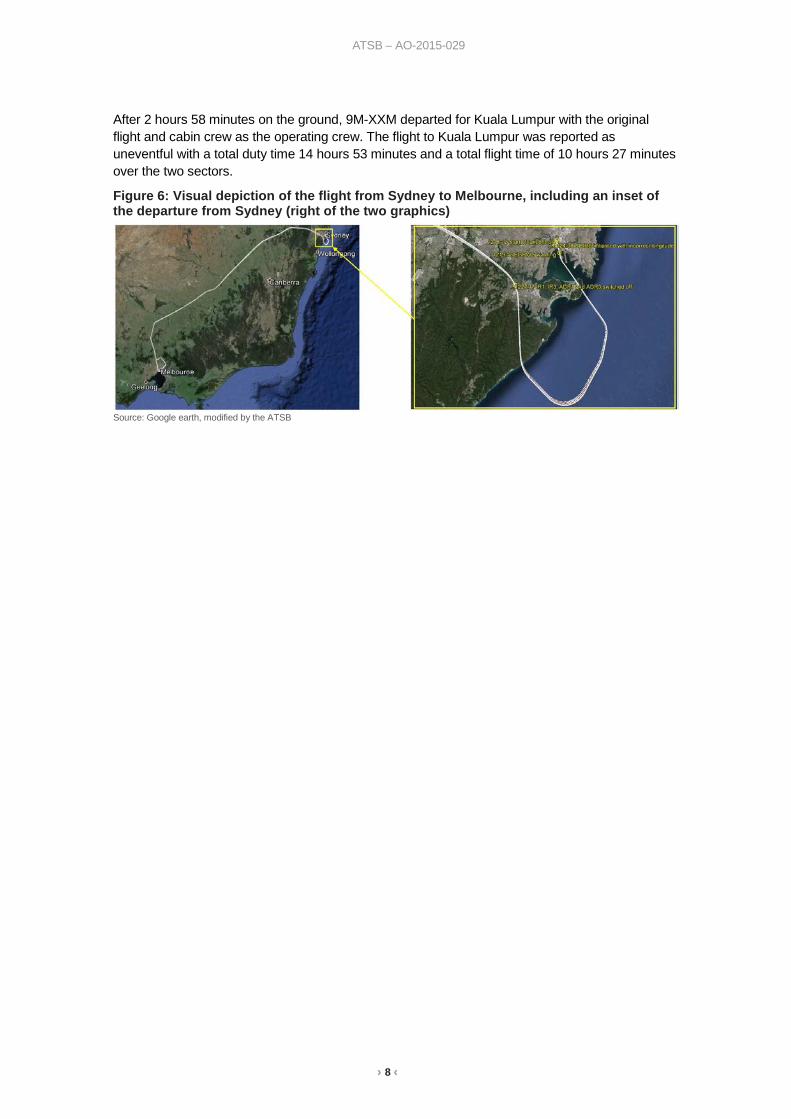
After consideration of the available alternatives, ATC established that en route and arrival conditions for Melbourne Airport, Victoria (approximately 390 NM (722 km) to the south-west of Sydney) were clear with only a few4 clouds at 3,000 ft in the vicinity of the airport. The flight crew considered and accepted the option of recovering to Melbourne Airport and ATC coordinated with the en route, arrival, approach and Melbourne tower controllers for the flight crew to receive continuous radar vectors from the aircraft’s current position to touchdown in Melbourne.
The flight crew continued their attempts to restore the flight guidance and navigation systems while in the Sydney area. The FO then carried out the IRS ALIGNMENT IN ATT MODE checklist from the QRH, restoring some ND and PFD functions; however, the heading needed to be periodically updated to allow for inertial drift. As per system design, the aircraft also remained in alternate law, and the autopilot and autothrust systems remained inoperative.
The crew received radar vectors and climb clearances to FL 310 en route to Melbourne. The aircraft was manually-flown by the captain for the transit. The captain reported that increased sensitivity in roll was the most notable handling characteristic of alternate law. However, given the clear daylight conditions and radar coverage, the flight was manageable and the aircraft was radar vectored to short final for runway 16 at Melbourne Airport (Figure 6). During the approach, with the aircraft fully-configured for a Flap 3 landing as per the alternate law checklist, the flight crew noted the aircraft became high on approach with the airspeed too high. As a result, the crew discontinued the approach and conducted a go-around.
Both flight crew stated that, during the initial part of the go-around, they heard an aural warning similar to a flap overspeed warning. This warning indicated the aircraft’s speed was too high for the selected flap setting. However, on checking their airspeed, both flight crew noted that it was below the maximum permissible 186 kt for the Flap 3 configuration being used. Flight recorder data indicated that the maximum recorded speed was 185 kt for 1 second while in this configuration and the post-flight report5 did not record any airspeed exceedances during any phase of the flight.
An EGPWS alert activated at approximately 600 ft during the initial approach at Melbourne, seconds prior to the commencement of the go-around. An assessment of recorded parameters indicated that, as with the EGPWS alert departing Sydney, this was also a spurious warning associated with the aircraft’s incorrect position information. There was no indication that the flight crew responded to the EGPWS approaching Melbourne.
The crew conducted a visual circuit and landed runway 16 at 1403, 1 hour 54 minutes after becoming airborne in Sydney. The aircraft landed below the maximum landing weight with the use of a single thrust reverser (see the section titled Aircraft information). Fuel jettison was not necessary due to high fuel burn while troubleshooting near Sydney at relatively low altitudes. On exiting the runway, the flight crew informed ATC that emergency services were not necessary and the aircraft taxied to a terminal gate.
Extensive troubleshooting was carried out on the aircraft and its systems by ground engineering services. This included swapping around of the ADIRUs and powering down the entire FMGS to try and replicate the situation encountered by the flight crew. No faults were found.
4 Cloud cover is normally reported using expressions that denote the extent of the cover. The expression few indicates
that up to a quarter of the sky was covered. 5 The post-flight report was an electronic report that the aircraft generated at the conclusion of each flight. It informed the
operator and/or maintenance organisation of faults detected during the flight. Whilst the majority of major faults were included within the post-flight reporting parameters, not every fault would be reported.
› 8 ‹
ATSB – AO-2015-029
After 2 hours 58 minutes on the ground, 9M-XXM departed for Kuala Lumpur with the original flight and cabin crew as the operating crew. The flight to Kuala Lumpur was reported as uneventful with a total duty time 14 hours 53 minutes and a total flight time of 10 hours 27 minutes over the two sectors.
Figure 6: Visual depiction of the flight from Sydney to Melbourne, including an inset of the departure from Sydney (right of the two graphics)
Source: Google earth, modified by the ATSB

› 9 ‹
ATSB – AO-2015-029
Context Personnel information Both flight crew reported having 24 hours rest at a hotel in Sydney prior to the occurrence flight, and having received adequate rest and sustenance. Both reported being in good health with no external stresses or distractions.
Captain The captain held an Air Transport Pilot (Aeroplane) Licence with an Airbus A330 command endorsement. He held a current Class 1 medical with a requirement to wear vision correction. The captain had a total of 22,580 hours flying experience, mostly on Boeing-type aircraft flying for other operators. He had converted to the A330 as a captain approximately 18 months prior to the occurrence, when commencing employment with Air Asia X.
First officer The first officer (FO) held a held an Air Transport Pilot (Aeroplane) Licence with an Airbus A330 P2 (copilot) endorsement. He held a current Class 1 medical without restrictions. The FO had a total of 2,200 flying hours, converting as FO to the A330 approximately 2 years prior to the occurrence, when commencing employment with Air Asia X.
Aircraft maintenance information Maintenance status On arrival at the aircraft, the captain and FO were met in the aircraft’s cabin by the previous flight crew. They were informed of a Minimum Equipment List (MEL) item that recorded one of the engines’ thrust reversers being inoperative, as well as a minor defect affecting one of the aircraft’s taxi lights. An inoperative thrust reverser and/or taxi light is a permissible fault with only minor impact on A330 operation and deemed not relevant to this occurrence.
Airbus service bulletin Airbus service bulletin SB 34-3287 Enhanced ADIRU alignment on GPS position became available in 2013 and was recommended by Airbus for incorporation in the A330. This service bulletin is designed to upgrade the air data and inertial reference system (ADIRS) (see the section titled Aircraft navigation system) in various A320, A330, and A340 aircraft such that position initialisation occurs automatically using the aircraft’s global positioning system (GPS)-derived position or, in the event the initialisation is carried out manually, when the pilot-entered initialisation position is crosschecked with the GPS position. If the crosschecked positions are not consistent, the pilot-entered position is rejected. Airbus advised that the objective of this service bulletin was to reduce the time required for ADIRS alignment and to reduce positional data entry errors.
Although recommended by Airbus, this service bulletin SB 34-3287 was not mandatory. At the time of writing, approximately 46 per cent of the 515 aircraft affected by the service bulletin have completed the upgrade. Airbus records suggest that approximately two occurrences are reported per annum that are attributable to position initialisation error in aircraft that have not been upgraded.
For reasons that could not be determined, 9M-XXM, had not received the ADIRS upgrade detailed in service bulletin SB 34-3287.
› 10 ‹
ATSB – AO-2015-029
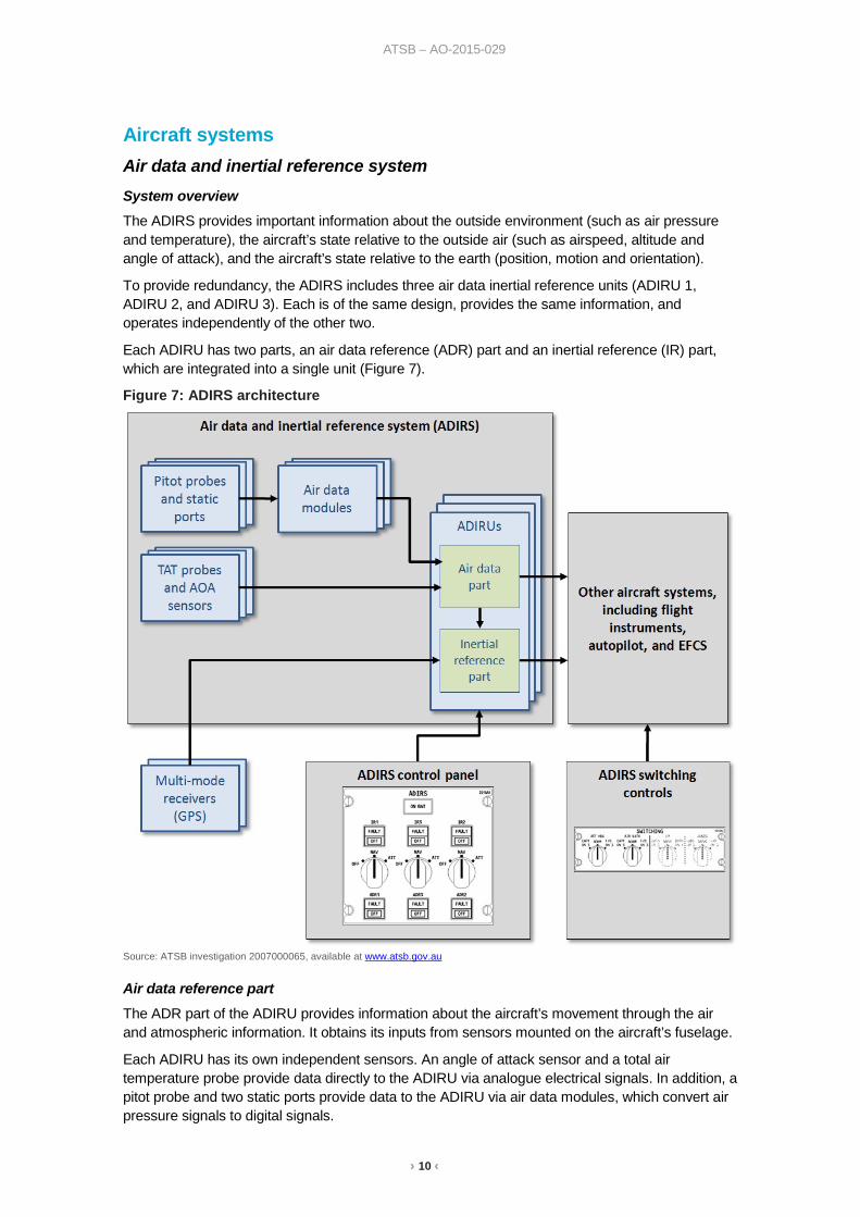
Aircraft systems Air data and inertial reference system System overview The ADIRS provides important information about the outside environment (such as air pressure and temperature), the aircraft’s state relative to the outside air (such as airspeed, altitude and angle of attack), and the aircraft’s state relative to the earth (position, motion and orientation).
To provide redundancy, the ADIRS includes three air data inertial reference units (ADIRU 1, ADIRU 2, and ADIRU 3). Each is of the same design, provides the same information, and operates independently of the other two.
Each ADIRU has two parts, an air data reference (ADR) part and an inertial reference (IR) part, which are integrated into a single unit (Figure 7).
Figure 7: ADIRS architecture
Source: ATSB investigation 2007000065, available at www.atsb.gov.au
Air data reference part The ADR part of the ADIRU provides information about the aircraft’s movement through the air and atmospheric information. It obtains its inputs from sensors mounted on the aircraft’s fuselage.
Each ADIRU has its own independent sensors. An angle of attack sensor and a total air temperature probe provide data directly to the ADIRU via analogue electrical signals. In addition, a pitot probe and two static ports provide data to the ADIRU via air data modules, which convert air pressure signals to digital signals.
› 11 ‹
ATSB – AO-2015-029
Inertial reference part
The IR part of the ADIRU provides information about the aircraft’s position, orientation, and velocity with respect to the earth. It obtains its data from a set of inertial instruments in each ADIRU, which continually measure acceleration in all three axes (pitch, roll and yaw) as well as rotational movement.
The IR part constantly updates the aircraft’s three-dimensional position and orientation based on the movement it senses from a known starting position and orientation. The process of determining this starting position is known as ‘position initialisation’, and occurs prior to each flight when the aircraft is stationary. Subsequent inertial measurements change the calculated position, orientation and velocity by a very small amount for each measurement cycle. As the IR parameters are dependent on previous values, an error during position initialisation would affect subsequent values. The IR parameters are also highly interdependent, and an error in one parameter would affect other parameters.
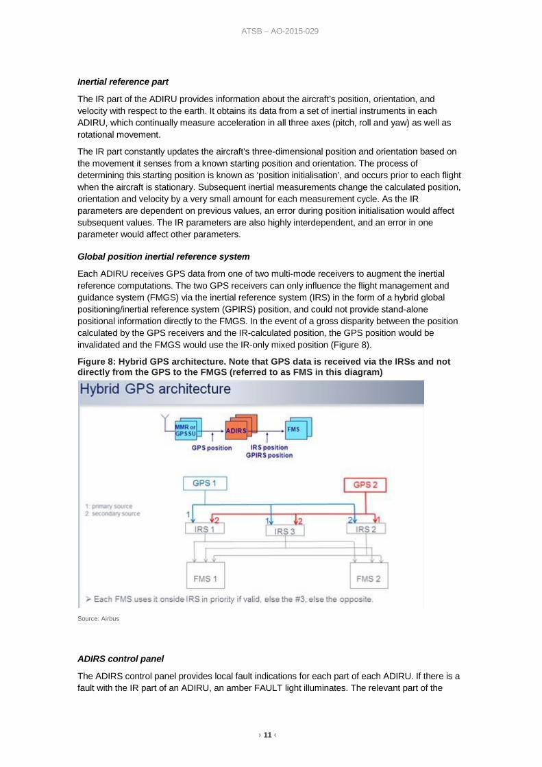
Global position inertial reference system
Each ADIRU receives GPS data from one of two multi-mode receivers to augment the inertial reference computations. The two GPS receivers can only influence the flight management and guidance system (FMGS) via the inertial reference system (IRS) in the form of a hybrid global positioning/inertial reference system (GPIRS) position, and could not provide stand-alone positional information directly to the FMGS. In the event of a gross disparity between the position calculated by the GPS receivers and the IR-calculated position, the GPS position would be invalidated and the FMGS would use the IR-only mixed position (Figure 8).
Figure 8: Hybrid GPS architecture. Note that GPS data is received via the IRSs and not directly from the GPS to the FMGS (referred to as FMS in this diagram)
Source: Airbus
ADIRS control panel
The ADIRS control panel provides local fault indications for each part of each ADIRU. If there is a fault with the IR part of an ADIRU, an amber FAULT light illuminates. The relevant part of the
› 12 ‹
ATSB – AO-2015-029
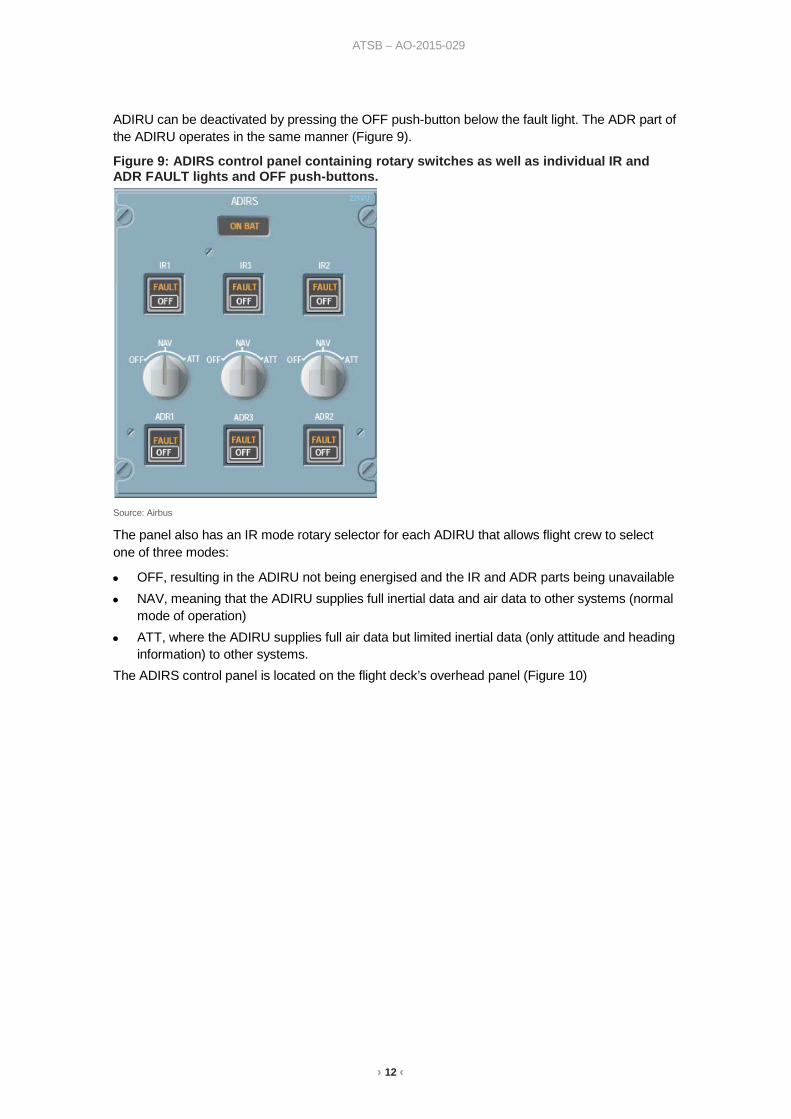
ADIRU can be deactivated by pressing the OFF push-button below the fault light. The ADR part of the ADIRU operates in the same manner (Figure 9).
Figure 9: ADIRS control panel containing rotary switches as well as individual IR and ADR FAULT lights and OFF push-buttons.
Source: Airbus
The panel also has an IR mode rotary selector for each ADIRU that allows flight crew to select one of three modes:
• OFF, resulting in the ADIRU not being energised and the IR and ADR parts being unavailable
• NAV, meaning that the ADIRU supplies full inertial data and air data to other systems (normal mode of operation)
• ATT, where the ADIRU supplies full air data but limited inertial data (only attitude and heading information) to other systems.
The ADIRS control panel is located on the flight deck’s overhead panel (Figure 10)
› 13 ‹
ATSB – AO-2015-029
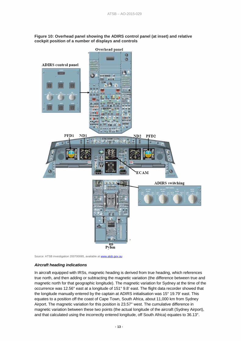
Figure 10: Overhead panel showing the ADIRS control panel (at inset) and relative cockpit position of a number of displays and controls
Source: ATSB investigation 200700065, available at www.atsb.gov.au
Aircraft heading indications
In aircraft equipped with IRSs, magnetic heading is derived from true heading, which references true north, and then adding or subtracting the magnetic variation (the difference between true and magnetic north for that geographic longitude). The magnetic variation for Sydney at the time of the occurrence was 12.56° east at a longitude of 151° 9.8’ east. The flight data recorder showed that the longitude manually entered by the captain at ADIRS initialisation was 15° 19.79’ east. This equates to a position off the coast of Cape Town, South Africa, about 11,000 km from Sydney Airport. The magnetic variation for this position is 23.57° west. The cumulative difference in magnetic variation between these two points (the actual longitude of the aircraft (Sydney Airport), and that calculated using the incorrectly entered longitude, off South Africa) equates to 36.13°.
› 14 ‹
ATSB – AO-2015-029
The difference between the runway direction and the magnetic heading indicated by the aircraft was approximately 38°.
The standby compass gets its reading directly from the earth’s magnetic field and therefore was not affected by the magnetic variation.
Procedural controls In modern aircraft systems the ability to prevent, detect and/or rectify an error or fault is achieved largely through the use of procedural controls. Procedural controls include, but are not limited to, standard practices and procedures that the crew are trained to undertake throughout the flight to ensure the systems are set-up and running correctly. They are often referred to as standard operating procedures and abnormal procedures, both of which encompass such things as the standardised and coordinated order in which a series of steps are undertaken (scan action flows), and checklists to ensure that the pertinent steps are completed correctly. These scan action flows and checklists are described in the flight crew training manual (FCTM), flight crew operations manual (FCOM) amplified procedures, quick reference handbook (QRH) and flight crew operations manual supplementary procedures (FCOM SUPS). These standardised and ordered actions are supplemental to sound aircraft system knowledge and good piloting practices gained through training and experience.
Initialisation of the air data and inertial reference system Part of the cockpit preparation procedures involved the alignment of the ADIRS. As detailed previously, this system utilised three independent ADIRUs, as well as GPS and air sensors to complete its multiple functions.
The exact procedure and requirement for ADIRS alignment varied slightly between aircraft subject to the age, manufacture and service bulletin status of the FMGS components. This status was listed in the various operating and training manuals by the Airbus manufacturer serial number for each aircraft. For 9M- XXM, this serial number was 0741.
In the case of 9M-XXM, a full alignment was carried out by first selecting all three ADIRS rotary selectors on the overhead panel to OFF for more than 5 seconds and then selecting these to NAV. The next step involved the position initialisation of the IRS. Using the multipurpose and control display unit (MCDU) position initialisation page, the crew can check/modify the MCDU coordinates before submitting these to the ADIRS.
With regard to the best position for IRS initialisation, the FCOM SUPPS included the following text:
The most appropriate coordinates for IRS position initialisation are the gate coordinates.
When the flight crew enters or modifies the origin airport (FROM) or the CO RTE, the MCDU INIT coordinates are reset to the Aerodrome Reference Point (ARP). The pilot may manually modify these coordinates.
The FCTM also included the following text applicable to 9M-XXM:
MANUAL POSITION INITIALIZATION (AIRCRAFT WITH OR WITHOUT MP S16804)
The coordinates of the departure Airport Reference Point (ARP) are displayed on the MCDU INIT page.
However, the most appropriate coordinates for IRS position initialization are the gate coordinates.
In this case, and in order to avoid entry errors, the flight crew should use the slew keys successively for latitude and longitude, instead of inserting the coordinates on the scratchpad.
The slew keys mentioned in the FCTM were two up and down keys on the MCDU that allow the pilot to incrementally adjust a value displayed on the MCDU screen, without having to retype the entire value. In the case of the ADIRS initialisation, these slew keys enabled the pilot to adjust the latitude and longitude of the initialisation position from the ARP to the gate coordinates without having to retype the entire coordinates. (Figure 11)
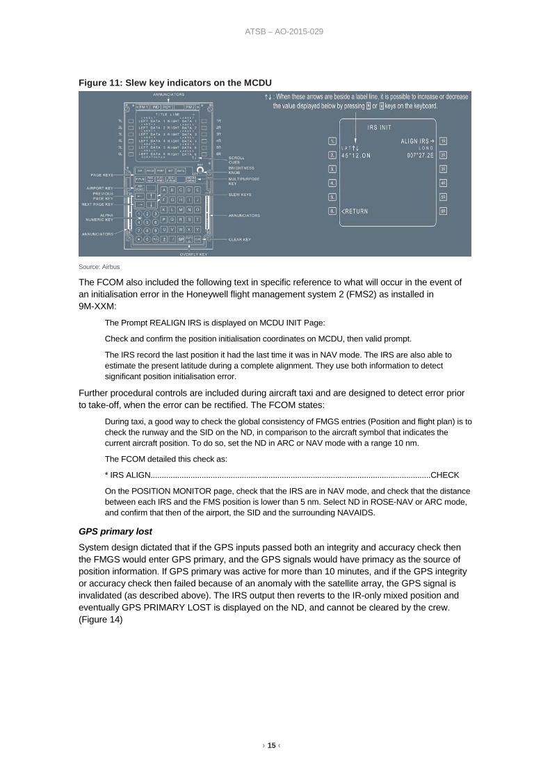
› 15 ‹
ATSB – AO-2015-029
Figure 11: Slew key indicators on the MCDU
Source: Airbus The FCOM also included the following text in specific reference to what will occur in the event of an initialisation error in the Honeywell flight management system 2 (FMS2) as installed in 9M-XXM:
The Prompt REALIGN IRS is displayed on MCDU INIT Page:
Check and confirm the position initialisation coordinates on MCDU, then valid prompt.
The IRS record the last position it had the last time it was in NAV mode. The IRS are also able to estimate the present latitude during a complete alignment. They use both information to detect significant position initialisation error.
Further procedural controls are included during aircraft taxi and are designed to detect error prior to take-off, when the error can be rectified. The FCOM states:
During taxi, a good way to check the global consistency of FMGS entries (Position and flight plan) is to check the runway and the SID on the ND, in comparison to the aircraft symbol that indicates the current aircraft position. To do so, set the ND in ARC or NAV mode with a range 10 nm.
The FCOM detailed this check as:
* IRS ALIGN..............................................................................................................................CHECK
On the POSITION MONITOR page, check that the IRS are in NAV mode, and check that the distance between each IRS and the FMS position is lower than 5 nm. Select ND in ROSE-NAV or ARC mode, and confirm that then of the airport, the SID and the surrounding NAVAIDS.
GPS primary lost System design dictated that if the GPS inputs passed both an integrity and accuracy check then the FMGS would enter GPS primary, and the GPS signals would have primacy as the source of position information. If GPS primary was active for more than 10 minutes, and if the GPS integrity or accuracy check then failed because of an anomaly with the satellite array, the GPS signal is invalidated (as described above). The IRS output then reverts to the IR-only mixed position and eventually GPS PRIMARY LOST is displayed on the ND, and cannot be cleared by the crew. (Figure 14)

› 16 ‹
ATSB – AO-2015-029
Figure 14: GPS PRIMARY LOST displayed (in amber) at the bottom-left of an exemplar ND
Source: Air Asia X, modified by the ATSB
Electronic centralised aircraft monitoring
System overview
The electronic centralised aircraft monitoring (ECAM) system is a main component of the Airbus two-crewmember cockpit and takes account of the ‘dark cockpit’ and ‘forward-facing crew’ philosophies. ‘Dark cockpit’ refers to only illuminating the flight deck switches and buttons that require the pilot’s attention and ‘forward facing’ refers to ensuring that essential flight information is readily available in the pilot’s immediate field of view. These philosophies are aimed at supporting crew actions by only displaying the minimum required information and reducing nuisance alerts.
The purpose of the ECAM is to:
• display aircraft system information
• monitor aircraft systems
• indicate required flight crew actions in most normal, abnormal and emergency situations • diagnose and respond to system faults. As the ECAM is available in most failure situations, it is a significant step in the direction towards a paperless cockpit and the reduction of items that must be conducted from memory by the crew.
The ECAM provides information on two display units located in the centre of the instrument panel (Figure 12).
The upper unit, or engine/warning display (E/WD), presents information such as engine primary indications, fuel quantity information and slats/flap positions. The bottom part of the E/WD presents warning or caution messages when a system fault occurs and memo messages when there are no faults.

› 17 ‹
ATSB – AO-2015-029
Figure 12. Engine/warning display (E/WD) showing exemplar engine parameters, fuel quantity and flap/slat positions (top of the display), take-off and landing memo messages, independent/primary warning/caution messages and required actions (bottom-left) and normal memo and secondary failure messages (bottom right)
Source ATSB investigation 200700065, available at www.atsb.gov.au
The lower unit, or system display, presents more detailed information for different systems. In some cases, the ECAM automatically provides the relevant system’s information following a system fault. The flight crew can also select different system pages. In addition, the system display presents a ‘status page’, which provides an operational summary of the aircraft’s status, including a list of inoperative systems, cancelled cautions, approach procedures and relevant limitations.
Presentation of ECAM warning and caution messages
The ECAM presents a short message indicating the nature of a warning or caution in red or amber, depending on the failure level. Any required crew actions are displayed in blue text on separate lines below the relevant message.
There are seven lines available at the bottom of the E/WD to display warning and caution messages. The messages are displayed in a priority order, with the most important (Level three) messages displayed at the top. In decreasing priority, Level two messages are displayed below the Level three messages but above Level one messages. When there were multiple messages at the same level, the most recent message has the highest priority.
If the flight crew complete a displayed action, the ECAM automatically removes the action line below the relevant message. The flight crew can also clear a message by pressing the ‘clear’ push-button. If the conditions that led to the presentation of a warning or caution message are no longer present, the ECAM automatically removes the message. If the conditions for the message return, the message is again displayed.

› 18 ‹
ATSB – AO-2015-029
Flight control laws System overview
The A330’s electrical flight control system (EFCS) is a fly-by-wire system. That is, there is no direct mechanical linkage between most of the flight crew’s controls and the flight control surfaces. Flight control computers send movement commands via electrical signals to hydraulic actuators that are connected to the control surfaces. The computers sense the response of the control surfaces to these commands and adjust the commands as required.
The EFCS computes the control orders according to a ‘control law’, with different functionality provided depending on the law being used. There are three levels of control law, each providing for different functionality as follows:
Normal law. The EFCS detects when the aircraft is approaching the limits of certain flight parameters, and commands control surface movements to prevent the aircraft from exceeding these limits (that is, it prevents the aircraft from exceeding a predefined safe flight envelope). Automatic flight-envelope protections include high angle of attack protection, load factor limitation, pitch attitude protection, roll attitude protection and high speed protection.
Alternate law. The EFCS switches to alternate law if there are certain types or combinations of failures within the flight control system or related systems. Some types of protection, such as high angle of attack protection, are not provided under this law, and others are provided using alternate logic.
Direct law. The EFCS switches to direct law in situations where there are more failures of relevant, redundant systems in addition to those that led to the reversion to alternate law. No flight-envelope protections are provided, and control surface deflection is proportional to sidestick and rudder pedal movement by the flight crew.
Enhanced ground proximity warning system In respect of the enhance ground proximity warning system activations during take-off from Sydney and again during approach in Melbourne, part of the system involved the comparison of the aircraft’s calculated position with a stored database of known terrain features and obstacles in the vicinity of major airports. System design took into account when the aircraft was likely to be on departure or arrival to these airports. It then modified the alerting functions such that there was a lower sensitivity to obstacles in the prescribed departure and/or arrival flight path when the aircraft was is the correct position, thus reducing nuisance warnings when no conflict with terrain or obstacles existed.
Master warning during the go-around at Melbourne During the initial part of the go-around in Melbourne, both flight crew heard an aural alert associated with a master warning similar to a flap overspeed warning. On checking the aircraft’s airspeed, both flight crew noted that the airspeed was below the maximum permissible 186 kt for the then Flap 3 configuration. Flight data indicated the maximum recorded speed was 185 kt for 1 second whilst in this configuration and the post flight report did not record any airspeed exceedances during any phase of flight.
A further review of flight data indicated that during the go-around the landing gear was selected up prior to the engine thrust levers reaching the take-off/go-around position. The flight crew reported that, in response, the captain reduced power below the take-off/go-around position to correct a suspected flap overspeed. As the aircraft was below 750 ft above ground level, this would likely have momentarily activated the L/G GEAR NOT DOWN master warning. The flap overspeed and L/G NOT DOWN master warnings have the same aural alert.

› 19 ‹
ATSB – AO-2015-029
Related occurrences ATSB investigation 200700065 On 11 January 2007, at about 0718 Eastern Daylight-saving Time, an Airbus A320 aircraft, registered ZK-OJB, departed runway 34L at Sydney Airport, New South Wales for Auckland, New Zealand and was assigned a radar heading by ATC. The controller noticed that the aircraft turned onto an incorrect heading and informed the flight crew. The crew checked the aircraft’s compasses and identified a heading error of about 40°and a GPS PRIMARY LOST message on the aircraft’s multi-purpose control and display unit and navigational display (ND). The crew advised ATC that they had navigational difficulties and elected to return to Sydney for landing.
When the aircraft returned to the departure gate, the flight crew noticed that the inertial reference system (IRS) was aligned to the incorrect longitude. The operator’s investigation into the incident found that the IRS had been aligned by maintenance staff prior to the crew boarding the aircraft. The incorrect alignment of the IRS was not noticed during a number of subsequent checks prior to departure.
As a result of this occurrence, the operator proposed developing a training program for all company pilots that was designed to improve discussion and guidance in relation to threat and error management issues.
ATSB occurrence report 201104899 On 13 July 2011, a Philippine Airlines Airbus A340, registered RP-C3431, departed Sydney and did not track as cleared by ATC. The flight crew reported navigation problems after crosschecking the standby and main heading indications and the aircraft returned to Sydney for a visual approach and landing.
The occurrence was reported to the ATSB and Airbus.
The crew reported to Airbus that during the take-off roll, they noticed the absence of the runway symbol on the ND and the annunciation of GPS PRIMARY LOST and NAV FM/IR POS DISAGREE on that display. Airbus included this occurrence in the number of global occurrences, detailed in the following section, relating to data entry errors during initialisation of the air data and inertial reference system.
Global occurrences and action At the time of writing, approximately 46 per cent of the 515 aircraft affected by service bulletin SB 34-3287 Enhanced ADIRU alignment on GPS position have been updated via that bulletin such that data entry is not required for ADIRS initialisation. Despite these updates, 13 occurrences have been reported to Airbus worldwide since January 2010 that are attributable to data entry error during ADIRS initialisation on aircraft that did not have the service bulletin completed. In each occurrence, the flight crew elected to return to the departure point, or a nearby airport via a visual approach.
› 20 ‹
ATSB – AO-2015-029
Safety analysis Introduction During pre-flight initialisation of the aircraft’s navigation systems, the longitude of the aircraft was entered incorrectly. This data entry error was not detected prior to take-off and resulted in disruption to various navigation and flight guidance systems. While troubleshooting was conducted by the flight crew once the aircraft was airborne, a lack of information from systems and checklists led to an incorrect diagnosis and actioning of flight deck switches. This in turn resulted in further degradation of the aircraft systems.
The following analysis will examine the aircraft systems, procedural controls, and human factors that contributed to the occurrence.
Available upgrade to aircraft navigation systems Airbus service bulletin SB 34-3287 Enhanced ADIRU [air data inertial reference unit] alignment on GPS position was released in 2013. Embodiment of this service bulletin into affected aircraft removed the need for data entry during the initialisation of the air data and inertial reference system (ADIRS). Furthermore, in the event that flight crew did elect to enter the aircraft’s position manually, any errors resulting from that action would be automatically corrected. As such, the enhancement provided by the service bulletin removed the possibility of the ADIRS being initialised to the wrong coordinates through a data entry error.
While compliance with the service bulletin was recommended by Airbus, it was not mandatory and the occurrence aircraft had not received this upgrade. Consequently, this important defence against data entry error was not available at the time of the occurrence.
Development of the occurrence
Data entry error Recorded aircraft flight data indicated that the ‘0’ digit of the departure gate longitude was omitted during manual entry of the aircraft’s position into the MCDU at the gate. This led to a longitude of 01519.8 east (15°19.79’ east) being entered instead of the correct value of 15109.8 east (151° 9.8’ east). That error resulted in the aircraft’s navigation systems being directed to a position near Cape Town, South Africa instead of Sydney Airport, Australia. An error in excess of 11,000 km. The magnitude of this error adversely affected the aircraft’s navigation functions, global positioning system (GPS) receivers and some electronic centralised aircraft monitoring (ECAM) alerts.
Airbus recommended that the aircraft’s position should be entered into the MCDU via that equipment’s slew keys. That method of data entry inherently limited the possibility of large errors, as the incremental nature of the slew keys required significant time to effect large changes in latitude and longitude. By contrast, the entry of latitude and longitude using the multipurpose and control display unit (MCDU) scratchpad involved the input of a sequence of 16 characters consisting of 12 numerical characters, two letters and two separate decimal points. This number of characters generally increases the likelihood for error when copying such a sequence from the gate sign to the scratchpad. On this occasion the use of the scratchpad directly facilitated the large positional error.
Kirwan (1994) examined data relating to error in tasks. The results showed a 3 per cent error rate for recall performance when recalling a six-digit sequence. While this is only partially relevant to this occurrence, the same error rate was present for entering seven-digit numbers into a key phone. Of interest, when conducting a routine operation where care is required, the error probability was 1 per cent. These error probability rates are fairly low; however, this kind of event
› 21 ‹
ATSB – AO-2015-029
is reasonably rare, as most data entry errors are detected in the cross-check or self-check after entry.
System error detection Manual entry of the aircraft’s position during ADIRS initialisation routinely results in the message prompt to ALIGN IRS. As this process is carried out on virtually every flight, it becomes an automatic action for flight crew. Automatic actions are not monitored closely and as such, any errors or incorrect actions will often be missed until it's too late to change them, or an unforeseen consequence has occurred (Reason, 1990).
In addition to the ALIGN IRS prompt, the magnitude of the positional change on this occasion would normally result in the prompt to also REALIGN IRS. The captain reported that some of the A330 fleet required ALIGN IRS to be selected twice, and that he could not remember if he carried out the alignment twice on the occurrence flight. That understanding was incorrect as, in the absence of a system fault, the prompt to ALIGN IRS only occurs once.
Examination of the aircraft’s navigation system following this occurrence did not identify any system fault that would have affected normal operation. It was therefore likely that, following entry of the incorrect aircraft position, ALIGN IRS was displayed, followed by the prompt to also REALIGN IRS. Differentiation between these two prompts would be made more difficult as they were displayed in a similar colour and in close proximity.
In summary, the aircraft’s navigation system probably displayed messages that would have enabled identification of the data entry error. However, due to a combination of the captain’s understanding that the same alignment-related message may be displayed twice, and the similarity between the messages, the error remained undetected.
Data entry crosscheck The cockpit preparation procedure called for the pilot monitoring to check the airfield data and all flight management system (FMS) entered data. The first officer (FO) stated that on his return from the pre-flight external inspection of the aircraft, the majority of the cockpit preparation had been completed. The FO then checked the data entries and switch positions as per standard operating procedures. The FO’s check of the FMS entries was a routine action carried out at the beginning of every flight, and the FO reported that it was rare for errors to be present and/or detected.
Expectancy can influence how and where people look for information (Wickens and McCarley, 2008). Expectancy can be influenced by habit, salience, event rate and relevance, among other factors.
In addition, various studies have shown a significant number of errors made by individuals are detected only when it is too late for effective intervention and recovery. Sarter and Alexander (2000) found that slips (consistent with the data entry error) were more likely to be detected based on routine or 'suspicious' checks, wherein crew suspected a problem and went looking for it, or observed the outcome of the slip.
Thomas, Petrilli and Dawson (2004) found that 'less than half the errors committed by crews were actually detected'. Another study in 2004 by Thomas noted that the majority of errors occurred during pre-flight, take-off and descent-approach-landing.
The combination of expectancy associated with a high frequency routine check with low suspicion of error, and a low chance of error detection during pre-flight, reduced the effectiveness of the FMGS check as a control in detecting the initialisation error. That probably led to the FO not noticing the incorrect initialisation coordinates during the crosscheck of the flight management and guidance system (FMGS) entries after completing the aircraft exterior inspection.
› 22 ‹
ATSB – AO-2015-029
Heading indication crosscheck The cockpit preparation procedure included the crosschecking of the primary heading indications on the navigation displays (NDs), primary flight displays (PFDs) and digital distance and radio magnetic indicator (DDRMI) against the standby compass indication. This check was designed to detect errors such as a heading disparity between the direct-reading standby compass and the primary heading indicators.
As the NDs, PFDs and DDRMI all receive their heading information from a respective ADIRU, on this occasion they would have displayed an equally incorrect heading as they were all influenced by the positional initialisation error. By contrast, the standby compass did not receive heading information from an ADIRU and would therefore have been reading correctly, subject to any magnetic interference. However, the standby indications are much smaller and set further away from the pilots than the indications on the ND, PFD and DDRMI and therefore less prominent. Apart from crosschecking the primary heading indicators, and in rare emergency procedures, the standby compass is rarely referenced by the flight crew.
The crew reported that the crosscheck was performed by one pilot reading out a heading and then both silently checking each heading indication against this value before saying ’Check’. This check did not include verbalising the displayed value.
In order to increase pilots’ awareness of aircraft modes and system states, aircraft manufacturers have recommended that pilots call out mode changes as they occur. While this is generally targeted at calling mode changes in-flight, the same benefit may be gained during ground checks. That is, by verbalising the indication or mode, greater attention is given by the flight crew. As a result, they are more likely to become aware of an error or discrepancy as their attention is directed toward comparing the indications.
Recorded data indicated that the ND modes selected during the pre-flight would not have displayed the heading on both of the pilot’s NDs. As such it would not have been possible to conduct the full heading indication crosscheck during the pre-flight, as detailed in the flight crew operations manual (FCOM).
In summary, it is likely that the disparity between the standby compass and the primary heading indications was not identified due to a combination of the:
• method of crosschecking the heading indications by use of the word ‘Check’ instead of verbalising the actual indication
• reduced prominence of the standby compass compared to the primary heading indications
• instrument panel check not being fully carried out during pre-flight in accordance with the FCOM, as the incorrect mode was selected on the NDs.
Flight plan comparison Following alignment of the ADIRS, the next step in the cockpit preparation was to check the FMGS-entered flight plan. Both pilots stated that this included checking the total track nautical miles and predicted fuel usage calculated by the FMGS against the values contained on the paper flight plan provided by their flight dispatch. Given the magnitude of the positional error, the ATSB considered whether this comparison provided an opportunity to detect the data entry error.
The check of the FMGS-entered flight plan was designed to ensure the correct flight plan and standard instrument departure (SID) were loaded prior to take-off. As such, the total track miles and fuel predictions were based the departure runway and active flight plan loaded into the flight management computer (FMC), and not influenced by the aircraft position calculated by the FMC. The total track miles and fuel predictions would therefore not differ from the paper flight plan provided by flight dispatch. As such, the comparison of total track miles in the FMC to the paper flight plan during pre-flight did not provide an opportunity to detect the initialisation error prior to
› 23 ‹
ATSB – AO-2015-029
take-off. Once airborne however, the total track miles and fuel predictions would have been erroneous as they incorporated the aircraft’s FMGS calculated position.
GPS accuracy check Both flight crew stated that seeing GPS PRIMARY and accuracy HIGH on the MCDU progress page during the pre-flight was, to them, an indication that the ADIRS was initialised and functioning correctly. Given that once airborne the crew noticed GPS PRIMARY LOST displayed on the ND, the ATSB considered whether the sequence of GPS-related messages may have provided an opportunity to detect the positional error before take-off.
The GPS PRIMARY message is typically displayed when the GPS is capable of passing the integrity and accuracy checks by receiving an adequate number of satellites in the correct positions relative to the aircraft and horizon. When this message is active, the two GPSs interface with the respective inertial reference system (IRS) and output a combined position to the FMC. If GPS PRIMARY is active for more than 10 minutes, and the GPS integrity or accuracy check then fail because of an anomaly with the satellite array, the GPS signal is invalidated. The IRS output then reverts to a mixed IRS only position (IRMIX) and eventually GPS PRIMARY LOST is displayed on the ND. There can be a delay of a few minutes between the invalidation of the GPS signal and display of GPS PRIMARY LOST.
During the occurrence the GPS PRIMARY and accuracy HIGH displays were observed prior to pushback and provided a false confirmation that the FMGS was set up correctly. It is probable that at this time the ADIRS initialisation was either incomplete or had not had enough time to invalidate the GPS signal. Eventually the aircraft used the erroneous position from the initialisation error to compare the satellite array, and invalidated the GPS signal. That would have removed the display of GPS PRIMARY and accuracy HIGH on the MCDU progress page. However, this did not occur until the aircraft was taxiing for departure, a time when the crew would not normally be observing that page. As a result, there was limited potential to identify the error.
The aircraft-generated post-flight report indicated that faults associated with failure of GPS integrity checks occurred 14 and 9 minutes prior to take-off. These failures were the result of the positional error and occurred while the aircraft was being taxied for take-off. Both of these faults are designed to have an associated single chime master caution aural alert, and the respective GPS NAV (1, 2) FAULT should appear on the engine/warning display. There were no associated ECAM messages indicating faults to either GPS.
The crew reported hearing two individual chimes during the taxi but, as there was no associated ECAM message, they continued with normal procedures and prepared for take-off. It is likely that a message associated with failure of the GPS integrity check did appear on the engine warning display but the crew did not recall seeing one.
Activation of the GPS NAV (1,2) FAULT alert would normally indicate a loss of GPS PRIMARY and result in the display of GPS PRIMARY LOST on the ND. However, due to complexity of the system there is variation in the time required to display this message. It was therefore not possible to determine if this message was displayed on the ND prior to take-off and remained unnoticed by the crew. Alternatively, GPS PRIMARY LOST may not have been displayed until the aircraft was airborne.
A review of the message display logic identified that the ECAM warning FMS/GPS POSITION DISAGREE also normally activates when an erroneous position is entered during IRS alignment. However, there was no evidence from the flight crew, flight data or post-flight report that this occurred. Advice from Airbus was that, similar to the above discussion regarding display of the GPS PRIMARY LOST message, there may not have been sufficient time for the message to be displayed.
› 24 ‹
ATSB – AO-2015-029
Data integrity checks The last step in the cockpit preparation procedure before conducting the take-off briefing was the ADIRS check. This check ensured that the distance between each IRS and each FMS position was less than 5 NM (9 km).
As each IRS was initialised to the same positional error, it was probable that the distances between each IRS and each FMS position were within the allowable limit. Likewise, prior to the conduct of this check there may have been sufficient time for the FMS to enter IRMIX mode and invalidate the hybrid global positioning/inertial reference system (GPIRS) position. In that case the FMS and IRS positions would not appear to differ and the error would remain unnoticed.
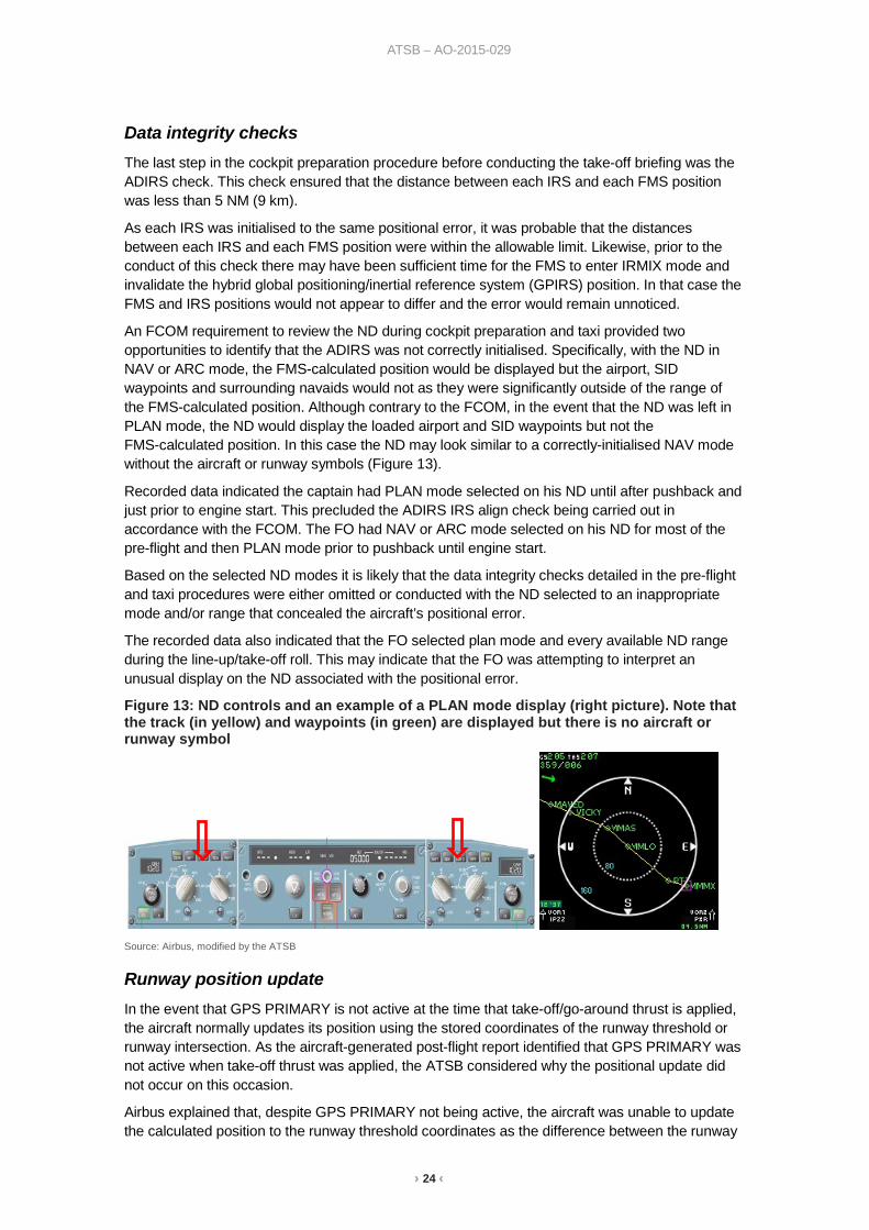
An FCOM requirement to review the ND during cockpit preparation and taxi provided two opportunities to identify that the ADIRS was not correctly initialised. Specifically, with the ND in NAV or ARC mode, the FMS-calculated position would be displayed but the airport, SID waypoints and surrounding navaids would not as they were significantly outside of the range of the FMS-calculated position. Although contrary to the FCOM, in the event that the ND was left in PLAN mode, the ND would display the loaded airport and SID waypoints but not the FMS-calculated position. In this case the ND may look similar to a correctly-initialised NAV mode without the aircraft or runway symbols (Figure 13).
Recorded data indicated the captain had PLAN mode selected on his ND until after pushback and just prior to engine start. This precluded the ADIRS IRS align check being carried out in accordance with the FCOM. The FO had NAV or ARC mode selected on his ND for most of the pre-flight and then PLAN mode prior to pushback until engine start.
Based on the selected ND modes it is likely that the data integrity checks detailed in the pre-flight and taxi procedures were either omitted or conducted with the ND selected to an inappropriate mode and/or range that concealed the aircraft’s positional error.
The recorded data also indicated that the FO selected plan mode and every available ND range during the line-up/take-off roll. This may indicate that the FO was attempting to interpret an unusual display on the ND associated with the positional error.
Figure 13: ND controls and an example of a PLAN mode display (right picture). Note that the track (in yellow) and waypoints (in green) are displayed but there is no aircraft or runway symbol
Source: Airbus, modified by the ATSB
Runway position update In the event that GPS PRIMARY is not active at the time that take-off/go-around thrust is applied, the aircraft normally updates its position using the stored coordinates of the runway threshold or runway intersection. As the aircraft-generated post-flight report identified that GPS PRIMARY was not active when take-off thrust was applied, the ATSB considered why the positional update did not occur on this occasion.
Airbus explained that, despite GPS PRIMARY not being active, the aircraft was unable to update the calculated position to the runway threshold coordinates as the difference between the runway
› 25 ‹
ATSB – AO-2015-029
threshold coordinates and the erroneous position was too large. The required positional correction was beyond the normal capabilities of the FMGS to update between the application of take-off/go-around thrust and the take-off.
Airborne flight management Due to the large data entry error remaining uncorrected, the navigation system did not initialise relative to the aircraft’s actual position prior to take-off. This likely affected the enhanced ground proximity warning system’s (EGPWS) ability to allow for the fact the aircraft was on departure, and resulted in spurious EGPWS activation shortly after take-off from Sydney Airport.
The captain reported being initially startled by the alert and, having visually confirmed that they were clear of terrain, became concerned that the FO would conduct an EGPWS escape manoeuvre. Such a manoeuvre involves separating the aircraft from terrain in the shortest possible distance by the use of as much as full control stick back pressure and all available engine power. The captain believed such an abrupt manoeuvre would increase the risk of a traffic conflict in the busy airspace and therefore instructed the FO to disregard the alert.
The FO engaged the autopilot at an altitude of approximately 400 ft which, in accordance with the SID was around the time the aircraft was required to conduct a right turn from the runway heading of 155° and track towards waypoint DUNES (an approximate heading of 170°). However, as the positional error resulted in the application of the wrong magnetic variation, an incorrect heading was displayed on the ND, PFD and DDRMI. Flight data indicated the aircraft’s indicated heading was 193° throughout the take-off roll, compared to the actual runway heading of 155°. In following the incorrect heading indications towards waypoint DUNES, the crew inadvertently turned left onto 170° and entered the departure flight path of the active parallel runway 16L.
During studies of distraction and interruptions during normal flight operations, distraction has been noted as a factor that can increase the opportunity for error (Loukopoulos, Dismukes & Barshi, 2001). It has also been shown to detract from effective monitoring (Loukopoulos, Dismukes & Barshi, 2003). In some cases this will be as a result of the requirement for a pilot’s attention to be on multiple tasks (Dismukes, Loukopoulos & Jobe, 2001). As such, distraction will often move the focus of attention from the intended task. In this context, it is likely that the spurious EGPWS alert distracted the crew from noticing that the aircraft was turning left and contrary to the SID, once the autopilot was engaged.
Both flight crew stated that in the early stages of flight, the cognitive workload was very high. This was supported when considering the activation of the EGPWS and subsequent determination that this was a spurious warning, combined with attempts to rationalise a number of alerting mechanisms such as air traffic control (ATC) informing the crew they were on the wrong heading, GPS PRIMARY LOST displaying on the ND, and the loss of most tracking and heading information at a critical stage of flight. The crew also stated they were concerned by the amount of traffic in the Sydney area and the potential for traffic conflict given their navigation difficulties.
Shortly after the FO engaged the autopilot, the captain took over the flying and ATC communication duties. The captain stated that due to a lack of any ECAM guidance, the only instruction he could give the FO was to reset the NAV.
The FO’s initial reaction was to refer to the UNRELIABLE AIRSPEED INDICATION checklist despite no guidance to do so from ECAM and no indication of a problem with the air data computers or airspeed sensors. The FO advised that in the weeks prior to the occurrence flight he had undergone a checking and training exercise which simulated conditions of frozen pitot airspeed probes. He stated that this, combined with recent media coverage of a fatal accident involving an A330 that experienced problems with the pitot system, put him in the mindset that they may be experiencing a fault in the air data reference (ADR).
The UNRELABLE AIRSPEED CHECKLIST provided target thrust settings and aircraft attitudes to assist the crew in flying the aircraft within the operating limitations in the event that the airspeed
› 26 ‹
ATSB – AO-2015-029
indicators became unreliable. It also contained guidance on identifying an affected ADR, which may have also contributed to the FO’s belief that there was an issue with the aircraft’s ADRs. Although flight data indicates that there was no sign of an ADR fault, this may have led the FO to turn ADR 1 and 3 OFF, inadvertently further degrading the flight systems.
There was limited information available to the crew to identify the risk associated with selecting an ADR to OFF. The flight crew training manual listed the identified risks associated with that action (appendix B) however, there was no guidance for fault diagnosis or rectification of the condition experienced by the crew of 9M-XXM. Additionally, the flight crew training manual is not routinely referenced in-flight, unlike the quick reference handbook or ECAM guidance.
Reliance on electronic centralised aircraft monitoring The FCTM describes the ECAM as a main component of Airbus aircraft that provides information in response to most failure situations. The captain attributed the lack of ECAM guidance before take-off as an indicator that the aircraft systems were operating correctly, despite two aural chimes associated with master cautions. The captain further stated that they had never experienced a chime with no associated ECAM message and that their response was to continue normal procedures. This behaviour is consistent with a reliance on ECAM to identify and resolve abnormal system situations.
The crew reported that the lack of ECAM guidance once airborne was a hindrance to resolving the situation. In the absence of ECAM or engine/warning display messages the FO searched the quick reference handbook and FCOM in an attempt to diagnose the problem. The FO carried out part of an UNRELIABLE AIRSPEED CHECKLIST and part of an ADR FAULT procedure before incorrectly using the ADIRS rotary switches in an attempt to rectify the situation.
The operating philosophy and views of the flight crew indicate a high expectancy that ECAM guidance would be available to resolve most abnormal situations, including that being experienced out of Sydney. In those rare situations where this guidance is not available, it could reasonably be expected that the risk of misidentification and/or inappropriate attempts to resolve the situation would increase.
Air traffic control support A review of the ATC response to this occurrence identified that the controllers carried out several tasks that reduced the risk to both the occurrence aircraft and other aircraft in the area. They were the first to notice and alert the crew to the tracking problem, and provided assistance to identify that the aircraft’s main heading indicators were erroneous. Additionally, ATC quickly resolved a possible conflict with another aircraft lined-up and ready to depart on the parallel runway.
Subsequently, coordination with several ATC units and the availability of continuous radar coverage provided the crew with a safe diversion alternate and vectoring from Sydney all the way to final approach in Melbourne. The captain reported that ATC had prevented the situation becoming a ‘dire emergency’ and that in many ways they had ‘saved the day’.

› 27 ‹
ATSB – AO-2015-029
Findings From the evidence available, the following findings are made with respect to data entry and navigational issues involving Airbus A330-343, registered 9M-XXM that occurred at Sydney Airport, New South Wales on 10 March 2015. These findings should not be read as apportioning blame or liability to any particular organisation or individual.
Contributing factors • When manually entering the coordinates of the aircraft’s position using a data entry technique
that was not recommended by the aircraft manufacturer, the longitude was incorrectly entered as 01519.8 east (15° 19.8’ east) instead of 15109.8 east (151° 9.8’ east). This resulted in a positional error in excess of 11,000 km, which adversely affected the aircraft’s navigation systems and some alerting systems.
• The aircraft was not fitted with an upgraded flight management system that would have negated the positional data entry error via either automated initialisation of the air data and inertial reference system, or the automatic correction of manual errors.
• The aircraft’s navigation system probably detected the data entry error and displayed an associated message. However, due to the combination of that message being similar to one displayed during routine alignment of the inertial reference system, and the captain’s understanding that the same alignment-related message may be displayed twice, the error was not identified.
• The first officer did not notice the error in the initialisation coordinates when crosschecking the flight management and guidance system entries after completing the pre-flight external inspection of the aircraft.
• It is likely that data integrity checks detailed in the pre-flight and taxi checklists were either omitted or conducted with the navigation display selected to an inappropriate mode and/or range that concealed the aircraft’s positional error.
• The instrument panels cockpit check was not carried out in accordance with the flight crew operations manual and resulted in the crew not detecting the offset error in the displayed heading.
• Due to the large data entry error remaining undetected, the navigation system did not initialise relative to the aircraft’s actual position prior to take-off. This resulted in an offset error in the displayed heading and a spurious enhanced ground proximity warning system alert shortly after take-off and again on arrival in Melbourne.
• Activation of the enhanced ground proximity warning system probably distracted the crew and prevented them noticing the turn towards the active parallel runway.
Other factors that increased risk • The crew were presented with an abnormal situation that did not have associated electronic
centralised aircraft monitoring or checklist guidance, and was not covered in any training or supplemental information. This increased the risk of misidentification of the situation and further degradation of the aircraft’s systems through incorrect cockpit switch selections.
Other findings • Effective monitoring and assistance provided by air traffic control reduced the risk to both the
occurrence aircraft and other aircraft in the area.
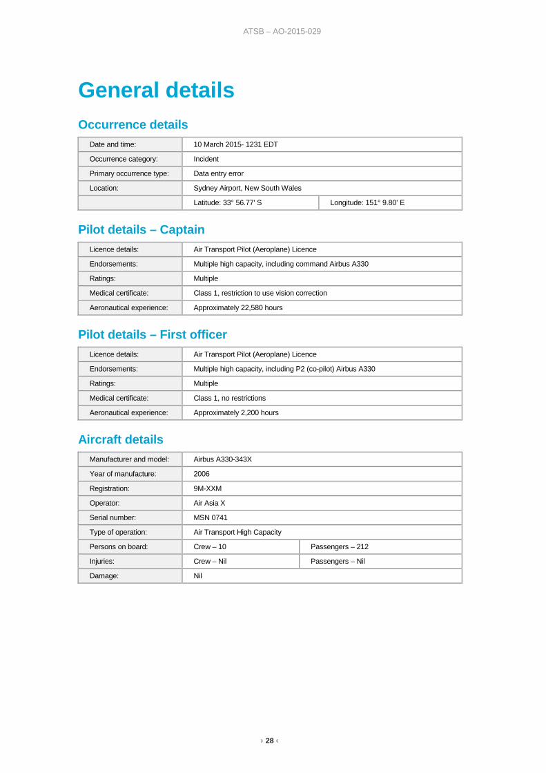
› 28 ‹
ATSB – AO-2015-029
General details Occurrence details
Date and time: 10 March 2015- 1231 EDT
Occurrence category: Incident
Primary occurrence type: Data entry error
Location: Sydney Airport, New South Wales
Latitude: 33° 56.77' S Longitude: 151° 9.80’ E
Pilot details – Captain Licence details: Air Transport Pilot (Aeroplane) Licence
Endorsements: Multiple high capacity, including command Airbus A330
Ratings: Multiple
Medical certificate: Class 1, restriction to use vision correction
Aeronautical experience: Approximately 22,580 hours
Pilot details – First officer Licence details: Air Transport Pilot (Aeroplane) Licence
Endorsements: Multiple high capacity, including P2 (co-pilot) Airbus A330
Ratings: Multiple
Medical certificate: Class 1, no restrictions
Aeronautical experience: Approximately 2,200 hours
Aircraft details Manufacturer and model: Airbus A330-343X
Year of manufacture: 2006
Registration: 9M-XXM
Operator: Air Asia X
Serial number: MSN 0741
Type of operation: Air Transport High Capacity
Persons on board: Crew – 10 Passengers – 212
Injuries: Crew – Nil Passengers – Nil
Damage: Nil
› 29 ‹
ATSB – AO-2015-029
Sources and submissions Sources of information The sources of information during the investigation included:
• Air Asia X
• the flight crew of 9M-XXM
• Airbus
• simulator recreations
• on board recorded data
• Airservices Australia.
References Airbus Flight Operations Support & Services. Getting to Grips with RNP AR. Customer Services Directorate, Airbus SAS Feb 2009.
Kirwan, B 1994, A guide to human reliability assessment Taylor and Francis, London.
Wickens, C.D and McCarley, J.S 2008, Applied Attention Theory Boca Raton CRC Press Chicago.
Sarter, N B. and Alexander, H M. 2000, Error Types and Related Error Detection Mechanisms in the Aviation Domain: An Analysis of Aviation Safety Reporting System Incident Reports, The International Journal of Aviation Psychology,10:2, pp. 189–206.
Thomas J.W, Petrilli R.M and Dawson D. 2004, an Exploratory Study of Error Detection Processes During Normal Line Operations, Centre for Applied Behavioural Science, University of South Australia, pp. 1–5.
Thomas, M. J. W. 2004, Predictors of Threat and Error Management: Identification of core non-technical skills and implications for training systems design. International Journal of Aviation Psychology, 14(2), pp. 207–231.
Loukopoulos, LD, Dismukes, RK & Barshi, I. Cockpit interruptions and distractions: A line observation study. In Proceedings of the 11th International Symposium on Aviation Psychology, Columbus, OH, 14–17 March 2001.
Dismukes, RK, Loukopoulos, LD & Kobe, KK. The challenges of managing concurrent and deferred tasks. In Proceedings of the 11th International Symposium on Aviation Psychology, Columbus, OH, 14–17 March 2001.
Loukopoulos, LD, Dismukes, RK & Barshi, I. Concurrent task demands in the cockpit: challenges and vulnerabilities in routine flight operations. In Proceedings of the 12th International Symposium on Aviation Psychology, Columbus, OH, 14–17 April 2003.
Submissions Under Part 4, Division 2 (Investigation Reports), Section 26 of the Transport Safety Investigation Act 2003 (the Act), the ATSB may provide a draft report, on a confidential basis, to any person whom the ATSB considers appropriate. Section 26 (1) (a) of the Act allows a person receiving a draft report to make submissions to the ATSB about the draft report.
A draft of this report was provided to the flight crew, Air Asia X, Airbus, the Bureau d’Enquêtes et d’Analyses, Airservices Australia and the Civil Aviation Safety Authority.

› 30 ‹
ATSB – AO-2015-029
Submissions were received from Airbus and Air Asia X. The submissions were reviewed and where considered appropriate, the text of the report was amended accordingly.
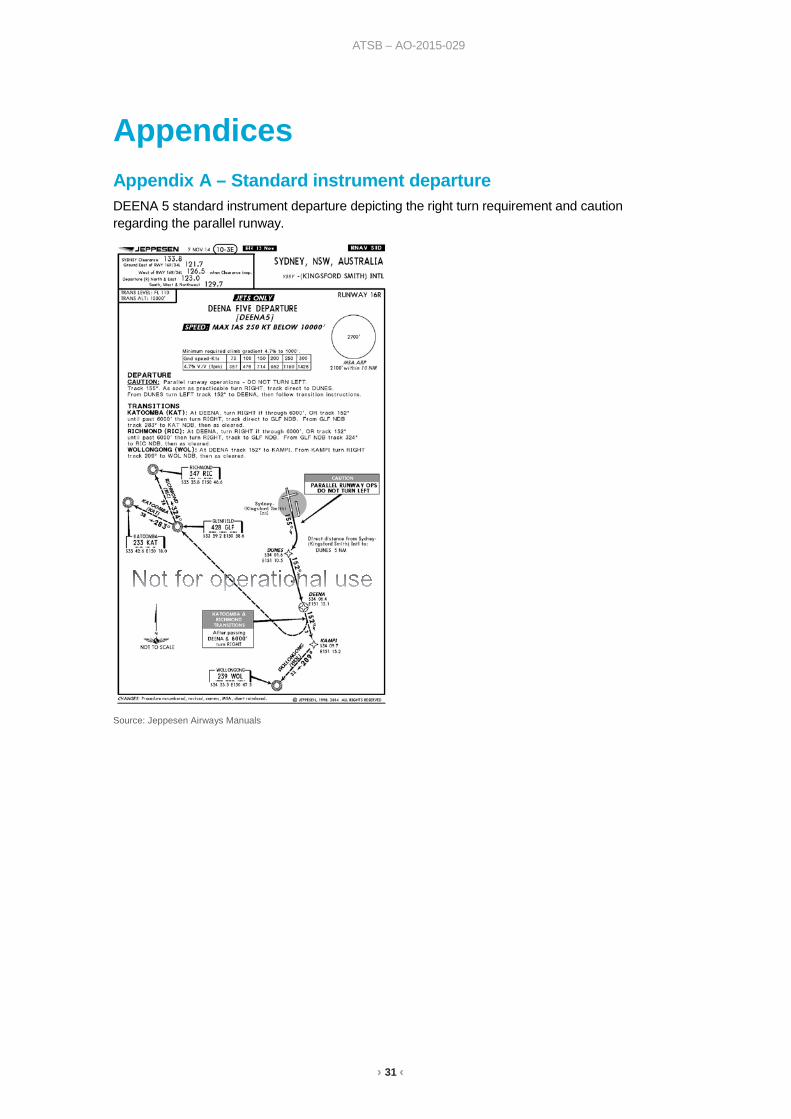
› 31 ‹
ATSB – AO-2015-029
Appendices Appendix A – Standard instrument departure DEENA 5 standard instrument departure depicting the right turn requirement and caution regarding the parallel runway.
Source: Jeppesen Airways Manuals
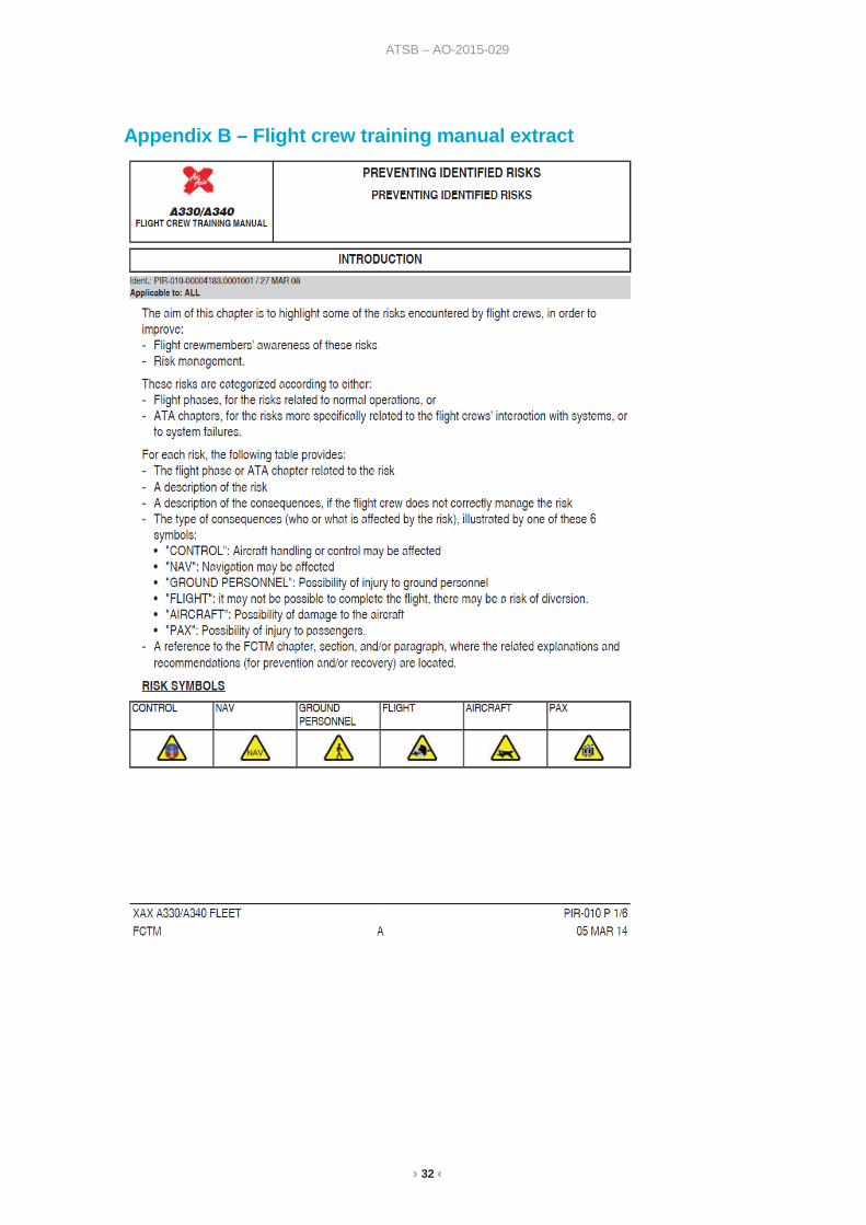
› 32 ‹
ATSB – AO-2015-029
Appendix B – Flight crew training manual extract

› 33 ‹
ATSB – AO-2015-029
Source: Air Asia X
› 34 ‹
ATSB – AO-2015-029
Australian Transport Safety Bureau The ATSB is an independent Commonwealth Government statutory agency. The ATSB is governed by a Commission and is entirely separate from transport regulators, policy makers and service providers. The ATSB’s function is to improve safety and public confidence in the aviation, marine and rail modes of transport through excellence in: independent investigation of transport accidents and other safety occurrences; safety data recording, analysis and research; fostering safety awareness, knowledge and action.
The ATSB is responsible for investigating accidents and other transport safety matters involving civil aviation, marine and rail operations in Australia that fall within Commonwealth jurisdiction, as well as participating in overseas investigations involving Australian registered aircraft and ships. A primary concern is the safety of commercial transport, with particular regard to operations involving the travelling public.
The ATSB performs its functions in accordance with the provisions of the Transport Safety Investigation Act 2003 and Regulations and, where applicable, relevant international agreements.
Purpose of safety investigations The object of a safety investigation is to identify and reduce safety-related risk. ATSB investigations determine and communicate the factors related to the transport safety matter being investigated.
It is not a function of the ATSB to apportion blame or determine liability. At the same time, an investigation report must include factual material of sufficient weight to support the analysis and findings. At all times the ATSB endeavours to balance the use of material that could imply adverse comment with the need to properly explain what happened, and why, in a fair and unbiased manner.
Developing safety action Central to the ATSB’s investigation of transport safety matters is the early identification of safety issues in the transport environment. The ATSB prefers to encourage the relevant organisation(s) to initiate proactive safety action that addresses safety issues. Nevertheless, the ATSB may use its power to make a formal safety recommendation either during or at the end of an investigation, depending on the level of risk associated with a safety issue and the extent of corrective action undertaken by the relevant organisation.
When safety recommendations are issued, they focus on clearly describing the safety issue of concern, rather than providing instructions or opinions on a preferred method of corrective action. As with equivalent overseas organisations, the ATSB has no power to enforce the implementation of its recommendations. It is a matter for the body to which an ATSB recommendation is directed to assess the costs and benefits of any particular means of addressing a safety issue.
When the ATSB issues a safety recommendation to a person, organisation or agency, they must provide a written response within 90 days. That response must indicate whether they accept the recommendation, any reasons for not accepting part or all of the recommendation, and details of any proposed safety action to give effect to the recommendation.
The ATSB can also issue safety advisory notices suggesting that an organisation or an industry sector consider a safety issue and take action where it believes it appropriate. There is no requirement for a formal response to an advisory notice, although the ATSB will publish any response it receives.
AT
SB
Transp
ort S
afety Rep
ort
Aviation O
ccurrence Investigation
Data entry and navigational issues involving A
irbus A330 343X
, 9M
XX
M S
ydney Airport, N
ew S
outh Wales, 10 M
arch 2015
AO
-2015-029
Final – 7 Septem
ber 2016
Investigatio
n
Australian Transport Safety Bureau
Enquiries 1800 020 616 Notifications 1800 011 034 REPCON 1800 011 034Web www.atsb.gov.auTwitter @ATSBinfoEmail [email protected] Facebook atsbgovau