Embed Size (px)
Citation preview

Data Acquisition Systems
CERN Summerstudent Programme 2008
Niko Neufeld, CERN-PH

Data Acquisition Systems, CERN Summerstudent Lecture 2008 2
Introduction
• Data Acquisition is a specialized engineering discipline thriving mostly in the eco-system of large science experiments, particularly in HEP
• It consists mainly of electronics, computer science, networking and (we hope) a little bit of physics
• Some material and lots of inspiration for this lecture was taken from lectures by my predecessors
• Many thanks to S. Suman for his help with the drawings!
Data Acquisition Systems, CERN Summerstudent Lecture 2008 3
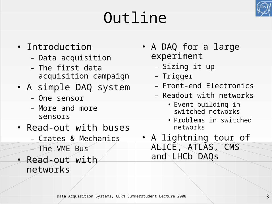
Outline
• Introduction– Data acquisition– The first data
acquisition campaign
• A simple DAQ system– One sensor– More and more sensors
• Read-out with buses– Crates & Mechanics – The VME Bus
• Read-out with networks
• A DAQ for a large experiment– Sizing it up– Trigger– Front-end Electronics– Readout with networks
• Event building in switched networks
• Problems in switched networks
• A lightning tour of ALICE, ATLAS, CMS and LHCb DAQs

Data Acquisition Systems, CERN Summerstudent Lecture 2008 4
Disclaimer
• Trigger and DAQ are two vast subjects covering a lot of physics and electronics
• Based entirely on personal bias I have selected a few topics
• While most of it will be only an overview at a few places we will go into some technical detail
• Some things will be only touched upon or left out altogether – information on those you will find in the references at the end– Electronics (lectures by J. Christiansen)– High Level Trigger (lectures by G. Dissertori)– DAQ of experiments outside HEP/LHC– Management of large networks and farms– High-speed mass storage– Experiment Control (= Run Control + Detector Control /
DCS)

Data Acquisition Systems, CERN Summerstudent Lecture 2008 5
Tycho Brahe and the Orbit of Mars
• First measurement campaign• Systematic data acquisition
– Controlled conditions (same time of the day and month)
– Careful observation of boundary conditions (weather, light conditions etc…) - important for data quality / systematic uncertainties
I've studied all available charts of the planets and stars and none of them match the others. There are just as many measurements and methods as there are astronomers and all of them disagree. What's needed is a long term project with the aim of mapping the heavens conducted from a single location over a period of several years.
Tycho Brahe, 1563 (age 17).

Data Acquisition Systems, CERN Summerstudent Lecture 2008 6
The First Systematic Data Acquisition
• Data acquired over 18 years, normally e every month• Each measurement lasted at least 1 hr with the naked eye• Red line (only in the animated version) shows comparison with modern theory

Data Acquisition Systems, CERN Summerstudent Lecture 2008 7
Tycho’s DAQ in Today’s Terminology
• Bandwith (bw) = Amount of data transferred / per unit of time– “Transferred” = written to his logbook– “unit of time” = duration of measurement – bwTycho = ~ 100 Bytes / h (compare with
LHCb 40.000.000.000 Bytes / s)
• Trigger = in general something which tells you when is the “right” moment to take your data– In Tycho’s case the position of the sun,
respectively the moon was the trigger– the trigger rate ~ 3.85 x 10⁻⁶ Hz (compare
with LHCb 1.0 x 10⁶ Hz)

Data Acquisition Systems, CERN Summerstudent Lecture 2008 8
Some More Thoughts on Tycho
• Tycho did not do the correct analysis of the Mars data, this was done by Johannes Kepler (1571-1630), eventually paving the way for Newton’s laws
• Morale: the size & speed of a DAQ system are not correlated with the importance of the discovery!

A Very Simple Data Acquisition System

Data Acquisition Systems, CERN Summerstudent Lecture 2008 10
Measuring Temperature
• Suppose you are given a Pt100 thermo-resistor
• We read the temperature as a voltage with a digital voltmeter
Data Acquisition Systems, CERN Summerstudent Lecture 2008 11
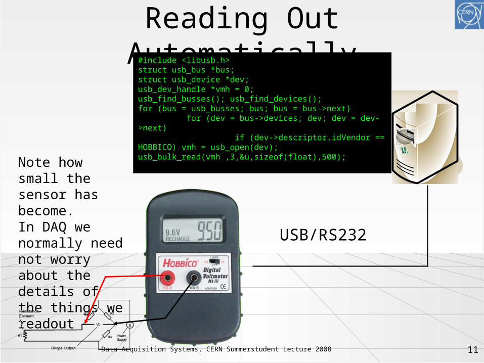
Reading Out Automatically
Note how small the sensor has become.In DAQ we normally need not worry about the details of the things we readout
USB/RS232
#include <libusb.h>struct usb_bus *bus; struct usb_device *dev; usb_dev_handle *vmh = 0; usb_find_busses(); usb_find_devices(); for (bus = usb_busses; bus; bus = bus->next)
for (dev = bus->devices; dev; dev = dev->next)
if (dev->descriptor.idVendor == HOBBICO) vmh = usb_open(dev);usb_bulk_read(vmh ,3,&u,sizeof(float),500);

Data Acquisition Systems, CERN Summerstudent Lecture 2008 12
Read-out 16 Sensors
• Buy 4 x 4-port USB hub (very cheap) (+ 3 more voltmeters)
• Adapt our little DAQ program
• No fundamental (architectural) change to our DAQ

Data Acquisition Systems, CERN Summerstudent Lecture 2008 13
Read-out 160 Sensors
• For a moment we (might) consider to buy 52 USB hubs, 160 Voltmeters
• …but hopefully we abandon the idea very quickly, before we start cabling this!
• Expensive, cumbersome, fragile our data acquisition system is not scalable

Read-out with Buses

Data Acquisition Systems, CERN Summerstudent Lecture 2008 15
A Better DAQ for Many (temperature) Sensors
• Buy or build a compact multi-port volt-meter module, e.g. 16 inputs
• Put many of these multi-port modules together in a common chassis or crate
• The modules need– Mechanical support– Power– A standardized way to
access their data (our measurement values)
• All this is provided by standards for (readout) electronics such as VME (IEEE 1014)
Backplane Connectors(for power and data)
VME Board Plugs into Backplane
7U VME Crate(a.k.a. “Subrack”)
19”
7U

Data Acquisition Systems, CERN Summerstudent Lecture 2008 16
DAQ for 160 Sensors Using VME
• Readout boards in a VME-crate– mechanical
standard for– electrical
standard for power on the backplane
– signal and protocol standard for communication on a bus

Data Acquisition Systems, CERN Summerstudent Lecture 2008 17
A Word on Mechanics and Pizzas
• The width and height of racks and crates are measured in US units: inches (in, '') and U – 1 in = 25.4 mm– 1 U = 1.75 in = 44.45 mm
• The width of a "standard" rack is 19 in.
• The height of a crate (also sub-rack) is measured in Us
• Rack-mountable things, in particular computers, which are 1 U high are often called pizza-boxes
• At least in Europe, the depth is measured in mm
• Gory details can be found in IEEE 1101.x (VME mechanics standard)
49 U
19 in
1 U

Data Acquisition Systems, CERN Summerstudent Lecture 2008 18
Communication in a Crate: Buses
• A bus connects two or more devices and allows them to communicate
• The bus is shared between all devices on the bus arbitration is required
• Devices can be masters or slaves (some can be both)
• Devices can be uniquely identified ("addressed") on the bus
Device 1
Master
Data Lines
Slave
Select Line
Device 2 Device 4Device 3Device 2 Device 4
Master
Data Lines
Slave
Select Line
Device 1 Device 3

Data Acquisition Systems, CERN Summerstudent Lecture 2008 19
Buses
• Famous examples: PCI, USB, VME, SCSI– older standards: CAMAC, ISA– upcoming: ATCA– many more: FireWire, I2C, Profibus, etc…
• Buses can be– local: PCI– external peripherals: USB– in crates: VME, compactPCI, ATCA– long distance: CAN, Profibus
Data Acquisition Systems, CERN Summerstudent Lecture 2008 20
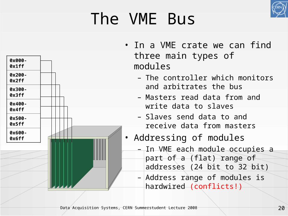
The VME Bus
• In a VME crate we can find three main types of modules– The controller which monitors
and arbitrates the bus– Masters read data from and
write data to slaves– Slaves send data to and
receive data from masters
• Addressing of modules– In VME each module occupies a
part of a (flat) range of addresses (24 bit to 32 bit)
– Address range of modules is hardwired (conflicts!)
0x000-0x1ff
0x200-0x2ff
0x300-0x3ff
0x400-0x4ff
0x500-0x5ff
0x600-0x6ff

Data Acquisition Systems, CERN Summerstudent Lecture 2008 21
VME protocol 1) Arbitration
• Arbitration: Master asserts*) BR#, Controller answers by asserting BG#
• If there are several masters requesting at the same time the one physically closest to the controller wins
• The winning master drives BBSY* high to indicate that the bus is now in use
Pictures from http://www.interfacebus.com*) assert means driving the line to logical 0 (VME control lines are inverted or active-low)

Data Acquisition Systems, CERN Summerstudent Lecture 2008 22
VME protocol 2) Write transfer • The Master writes
data and address to the data / respectively data bus
• It asserts DS* and AS* to signal that the data and address are valid
• The slave reads and acknowledges by asserting DTACK
• The master releases DS*, AS* and BSBSY*, the cycle is complete
• Note: there is no clock! The slave can respond whenever it wants. VME is an asynchronous bus

Data Acquisition Systems, CERN Summerstudent Lecture 2008 23
Speed Considerations
• Theoretically ~ 16 MB/s can be achieved– assuming the databus to be full 32-bit
wide– the master never has to relinquish bus
master ship• Better performance by using block-
transfers

Data Acquisition Systems, CERN Summerstudent Lecture 2008 24
VME protocol 3) Block transfer
• After an address cycle several (up to 256) data cycles are performed
• The slave is supposed to increment the address counter
• The additional delays for asserting and acknowledging the address are removed
• Performance goes up to 40 MB/s
• In PCI this is referred to as "burst-transfer"
• Block transfers are essential for Direct Memory Access (DMA)
• More performance can be gained by using the address bus also for data (VME64)
• Block transfers are essential for Direct Memory Access (DMA)
• More performance can be gained by using the address bus also for data (VME64)

Data Acquisition Systems, CERN Summerstudent Lecture 2008 25
Advantages of buses
• Relatively simple to implement– Constant number of lines– Each device implements the same
interface
• Easy to add new devices– topological information of the bus can
be used for automagically choosing addresses for bus devices: this is what plug and play is all about.

Data Acquisition Systems, CERN Summerstudent Lecture 2008 26
Buses for DAQ at LHC?
• A bus is shared between all devices (each new active device slows everybody down)– Bus-width can only be increased up to a certain point
(128 bit for PC-system bus)– Bus-frequency (number of elementary operations per
second) can be increased, but decreases the physical bus-length
• Number of devices and physical bus-length is limited (scalability!)– For synchronous high-speed buses, physical length is
correlated with the number of devices (e.g. PCI)– Typical buses have a lot of control, data and address
lines (look at a SCSI or ATA cable)
• Buses are typically useful for systems < 1 GB/s

Data Acquisition Systems, CERN Summerstudent Lecture 2008 27
Network based DAQ
• In large (HEP) experiments we typically have thousands of devices to read, which are sometimes very far from each other
• Network technology solves the scalability issues of buses– In a network devices are equal ("peers")– In a network devices communicate directly with each
other• no arbitration necessary• bandwidth guaranteed
– data and control use the same path• much fewer lines (e.g. in traditional Ethernet only two)
– At the signaling level buses tend to use parallel copper lines. Network technologies can be also optical, wire-less and are typically (differential) serial

Data Acquisition Systems, CERN Summerstudent Lecture 2008 28
Network Technologies
• Examples: – The telephone network – Ethernet (IEEE 802.3)– ATM (the backbone for GSM cell-phones)– Infiniband– Myrinet– many, many more
• Note: some of these have "bus"-features as well (Ethernet, Infiniband)
• Network technologies are sometimes functionally grouped– Cluster interconnect (Myrinet, Infiniband) 15 m – Local area network (Ethernet), 100 m to 10 km – Wide area network (ATM, SONET) > 50 km

Data Acquisition Systems, CERN Summerstudent Lecture 2008 29
Connecting Devices in a Network
• On an network a device is identifed by a network address– eg: our phone-number, the MAC address of
your computer• Devices communicate by sending
messages (frames, packets) to each other• Some establish a connection lilke the
telephone network, some simply send messages
• Modern networks are switched with point-to-point links– circuit switching, packet switching

Data Acquisition Systems, CERN Summerstudent Lecture 2008 30
Switched Networks
• In a switched network each node is connected either to another node or to a switch
• Switches can be connected to other switches
• A path from one node to another leads through 1 or more switches (this number is sometimes referred to as the number of "hops" )

Data Acquisition Systems, CERN Summerstudent Lecture 2008 31
A Switched Network
• While 2 can send data to 1 and 4, 3 can send at full speed to 5
• 2 can distribute the share the bandwidth between 1 and 4 as needed
5
41
2
3

Data Acquisition Systems, CERN Summerstudent Lecture 2008 32
Switches
• Switches are the key to good network performance
• They must move frames reliably and as fast as possible between nodes
• They face two problems– Finding the right path for a frame– Handling congestion (two or more
frames want to go to the same destination at the same time)

Data Acquisition Systems, CERN Summerstudent Lecture 2008 33
Ethernet
• Cheap• Unreliable – but in practice
transmission errors are very low• Available in many different speeds
and physical media• We use IP or TCP/IP over Ethernet• By far the most widely used local
area network technology (even starting on the WAN)

Data Acquisition Systems, CERN Summerstudent Lecture 2008 34
Ethernet Header
IP Header
UDP Header
Data
IP Packets over Ethernet
0 … 32 bits

Data Acquisition for a Large Experiment

Data Acquisition Systems, CERN Summerstudent Lecture 2008 36
Moving on to Bigger Things…
The CMS Detector

Data Acquisition Systems, CERN Summerstudent Lecture 2008 37
Moving on to Bigger Things…
?
• 15 million detector channels• @ 40 MHz• = ~15 * 1,000,000 * 40 * 1,000,000 bytes
• = ~ 600 TB/sec

Data Acquisition Systems, CERN Summerstudent Lecture 2008 38
Designing a DAQ System for a Large HEP Experiment
• What defines "large"?– The number of channels: for LHC experiments
O(107) channels• a (digitized) channel can be between 1 and 14 bits
– The rate: for LHC experiments everything happens at 40.08 MHz, the LHC bunch crossing frequency (This corresponds to 24.9500998 ns or 25 ns among friends)
• HEP experiments usually consist of many different sub-detectors: tracking, calorimetry, particle-ID, muon-detectors

Data Acquisition Systems, CERN Summerstudent Lecture 2008 39
First Questions
• Can we or do we want to save all the data?• How do we select the data• Is continuous read-out needed, i.e. an
experiment in a collider? Or are there idle periods mixed with periods with many events – this is typically the case for fixed-target experiments
• How do we make sure that the values from the many different channels refer to the same original event (collision)

Data Acquisition Systems, CERN Summerstudent Lecture 2008 40
What Do We Need to Read Out a Detector (successfully)?
• A selection mechanism (“trigger”)• Electronic readout of the sensors of the
detectors (“front-end electronics”) • A system to keep all those things in
sync (“clock”)• A system to collect the selected data
(“DAQ”)• A Control System to configure, control
and monitor the entire DAQ

Data Acquisition Systems, CERN Summerstudent Lecture 2008 41
Trigger• No (affordable) DAQ system
could read out O(107) channels at 40 MHz 400 TBit/s to read out – even assuming binary channels!
• What’s worse: most of these millions of events per second are totally uninteresting: one Higgs event every 0.02 seconds
• A first level trigger (Level-1, L1) must somehow select the more interesting events and tell us which ones to deal with any further
Black magic happening here

Data Acquisition Systems, CERN Summerstudent Lecture 2008 42
Inside the Box: How does a Level-1trigger work?
• Millions of channels : try to work as much as possible with “local” information– Keeps number of interconnections low
• Must be fast: look for “simple” signatures– Keep the good ones, kill the bad ones– Robust, can be implemented in hardware (fast)
• Design principle:– fast: to keep buffer sizes under control– every 25 nanoseconds (ns) a new event: have
to decide within a few microseconds (s): trigger-latency

Data Acquisition Systems, CERN Summerstudent Lecture 2008 43
Challenges for the L1 at LHC• N (channels) ~ O(107); ≈20 interactions every 25
ns– need huge number of connections
• Need to synchronize detector elements to (better than) 25 ns
• In some cases: detector signal/time of flight > 25 ns– integrate more than one bunch crossing's worth of
information– need to identify bunch crossing...
• It's On-Line (cannot go back and recover events)– need to monitor selection - need very good control over
all conditions

Data Acquisition Systems, CERN Summerstudent Lecture 2008 44
Know Your Enemy: pp Collisions at 14 TeV at 1034 cm-2s-1
(pp) = 70 mb --> >7 x 10⁸ /s (!)
• In ATLAS and CMS* 20 min bias events will overlap
• HZZZ H 4 muons:the cleanest(“golden”)signature
Reconstructed tracks with pt > 25 GeV
And this (not the H though…)
repeats every 25 ns…
*)LHCb @2x1033 cm-2-1 isn’t much nicer and in Alice (PbPb) it will be even worse

Data Acquisition Systems, CERN Summerstudent Lecture 2008 45
Mother Nature is a … Kind Woman After All
• pp collisions produce mainly hadrons with transverse momentum “pt” ~1 GeV
• Interesting physics (old and new) has particles (leptons and hadrons) with large pt:– We: M(W)=80 GeV/c2; pt(e) ~ 30-40 GeV– H(120 GeV): pt() ~ 50-60 GeV– BD*+ pt() ~ 1.4 GeV
• Impose high thresholds on the pt of particles – Implies distinguishing particle types;
possible for electrons, muons and “jets”; beyond that, need complex algorithms
• Conclusion: in the L1 trigger we need to watch out for high transverse momentum electrons, jets or muons
ptp

Data Acquisition Systems, CERN Summerstudent Lecture 2008 46
How to defeat minimum bias: transverse momentum pt
µ
e
n
p
Use prompt data (calorimetry and muons) to identify: High p
t electron, muon, jets,
missing ET
CALORIMETERs Cluster finding and energy deposition evaluation
MUON System Segment and track finding
New data every 25 ns Decision latency ~ µs

Data Acquisition Systems, CERN Summerstudent Lecture 2008 47
Distributing the L1 Trigger• Assuming now that a
magic box tells for each bunch crossing (clock-tick) yes or no– Triggering is not for
philosophers – “perhaps” is not an option
• This decision has to be brought for each crossing to all the detector front-end electronics elements so that they can send of their data or discard it
Global Trigger 1
Accept/Reject LV-1
Front-End Digitizer
Local level-1 triggerPrimitive e, , jets, µ
Pipeline delay ( ≈ 3 µs)
≈ 2-3 µs latency
loop
TriggerPrimitive
Generator

Data Acquisition Systems, CERN Summerstudent Lecture 2008 48
Clock Distribution and Synchronisation
• An event is a snapshot of the values of all detector front-end electronics elements, which have their value caused by the same collision
• A common clock signal must be provided to all detector elements– Since the c is constant,
the detectors are large and the electronics is fast, the detector elements must be carefully time-aligned
• Common system for all LHC experiments TTC based on radiation-hard opto-electronics
Plus:Trigger decisionBunch cross ID
40 MHz

Data Acquisition Systems, CERN Summerstudent Lecture 2008 49
Bird’s-Eye View on (front-end) Electronics
Amplifier
Filter
Shaper
Range compressionclock (TTC)
Sampling
Digital filter
Zero suppression
Buffer
Format & ReadoutBuffer
Feature extraction
Detector
to Data Acquisition System
All this explained in great detail by J. Christiansen this week --> focus on the green arrow on beyond

Data Acquisition Systems, CERN Summerstudent Lecture 2008 50
FEE & DAQ by electronics engineers
FEE = Front End Electronics
Example from LHCb
Data Acquisition Systems, CERN Summerstudent Lecture 2008 51
Data Acquisition
• Event-data are now digitized, pre-processed and tagged with a unique, monotonically increasing number
• The event data are distributed over many read-out boards (“sources”)
• For the next stage of selection, or even simply to write it to tape we have to get the pieces of the event together: event building

Event Building

Data Acquisition Systems, CERN Summerstudent Lecture 2008 53
Event Building
Data AcquisitionSwitch
To Trigger Algorithms
1Event fragments are received from detector front-end2
Event fragments are read out over a network to an event builder 3
Event builder assembles fragments into a complete event 4
Complete events are processed by trigger algorithms
Event Builder 3
Event Builder 3
Event Builder 3

Data Acquisition Systems, CERN Summerstudent Lecture 2008 54
Switch Buffer
Push-Based Event Building
Data AcquisitionSwitch
1Readout Supervisor tells readout boards where events must be sent (round-robin) 2
Readout boards do not buffer, so switch must 3
No feedback from Event Builders to Readout system
“Send next event
to EB1”
“Send next event
to EB2”
Event Builder 2
Event Builder 1
ReadoutSupervisor

Data Acquisition Systems, CERN Summerstudent Lecture 2008 55
Congestion
2
1 32 2
Bang
• "Bang" translates into random, uncontrolled packet-loss
• In Ethernet this is perfectly valid behavior and implemented by very cheap devices
• Higher Level protocols are supposed to handle the packet loss due to lack of buffering
• This problem comes from synchronized sources sending to the same destination at the same time

Data Acquisition Systems, CERN Summerstudent Lecture 2008 56
Overcoming Congestion:Queuing at the Input
• Two frames destined to the same destination arrive
• While one is switched through the other is waiting at the input port
• When the output port is free the queued packet is sent
2
1 32 2

Data Acquisition Systems, CERN Summerstudent Lecture 2008 57
Event Builder 1
Pull-Based Event Building
Data AcquisitionSwitch
1Event Builders notify Readout Supervisor of available capacity 2
Readout Supervisor ensures that data are sent only to nodes with available capacity 3
Readout system relies on feedback from Event Builders
“Send next event
to EB1”
“Send next event
to EB2”
EB1: EB2:EB3:
0 00
“Send me an event!”
“Send me an event!”
1 11
“Send me an event!”
“Send me an event!”
0 11
0 01 “Send
next event to EB3”
1 01
Event Builder 1
Event Builder 2
Event Builder 3

Data Acquisition Systems, CERN Summerstudent Lecture 2008 58
Head of Line Blocking
2
1 32 2
4
4
Packet to node 4 must waiteven though port to node 4 is free
• The reason for this is the First in First Out (FIFO) structure of the input buffer
• Queuing theory tells us* that for random traffic (and infinitely many switch ports) the throughput of the switch will go down to 58.6% that means on 100 MBit/s network the nodes will "see" effectively only ~ 58 MBit/s*) "Input Versus Output Queueing on a Space-
Division Packet Switch"; Karol, M. et al. ; IEEE Trans. Comm., 35/12

Data Acquisition Systems, CERN Summerstudent Lecture 2008 59
Output Queuing• In practice virtual
output queueing is used: at each input there is a queue for n ports O(n2) queues must be managed
• Assuming the buffers are large enough(!) such a switch will sustain random traffic at 100% nominal link load
2
1 32 2
4
4
Packet to node 2 waits at output toport 2. Way to node 4 is free

AACL
ALICE, ATLAS, CMS, LHCbDAQs in 4 slides

Data Acquisition Systems, CERN Summerstudent Lecture 2008 61
GDC GDCGDCGDC
ALICE DAQCTP
LTU
TTC
FERO FERO
LTU
TTC
FERO FERO
LDCLDC
BUSY BUSY
Rare/All
Event Fragment
Sub-event
Event
File
Storage Network 1250 MB/s
TDS
PDS
L0, L1a, L2
L0, L1a, L2
342 DDLs
EDM
LDCLoad Bal. LDC LDC
HLT Farm
FEPFEP
DDL
H-RORC
10 DDLs
10 D-RORC
10 HLT LDC
144 DDLs
TDS
DS DS
Event Building Network 2500 MB/s
416 D-RORC
194 Detector LDC
50 GDC25 TDS
5 DSS
•Two stage hardware trigger L0 + L1•High Level Trigger (HLT) on separate farm

Data Acquisition Systems, CERN Summerstudent Lecture 2008 626262
ATLAS DAQATLAS DAQATLAS
•L1 selects events at 100 kHz and defines regions of interest•L2 pulls data from the region of interest and processes the data in a farm of processorsL2 accepts data at ~ 1 kHz•Event Filter reads the entire detector (pull), processes the events in a farm and accepts at 100 Hz

Data Acquisition Systems, CERN Summerstudent Lecture 2008 63
Collision rate 40 MHzLevel-1 Maximum trigger rate
100 kHzAverage event size ≈1 MbyteEvent Flow Control ≈106 Mssg/s
No. of In-Out units 512Readout network bandwidth ≈
1 Terabit/s Event filter computing power ≈
106 SI95Data production ≈Tbyte/dayNo. of PC motherboards ≈Thousands
CMS DAQ
Congestion is handled by synchronizing the sources to send in discrete time-slots: Barrel Shifting

Data Acquisition Systems, CERN Summerstudent Lecture 2008 64
LHCb DAQ
SWITCH
HLT farm
Detector
TFC System
SWITCHSWITCH SWITCH SWITCH SWITCH SWITCH
READOUT NETWORK
L0 triggerLHC clock
MEP Request
Event building
Front-End
CPU
CPU
CPU
CPU
CPU
CPU
CPU
CPU
CPU
CPU
CPU
CPU
CPU
CPU
CPU
CPU
CPU
CPU
CPU
CPU
CPU
CPU
CPU
CPU
Readout Board
Expe
rimen
t Con
trol
Sys
tem
(EC
S)
VELO ST OT RICH ECal HCal MuonL0
Trigger
Event dataTiming and Fast Control SignalsControl and Monitoring data
SWITCH
MON farm
CPU
CPU
CPU
CPU
Readout Board
Readout Board
Readout Board
Readout Board
Readout Board
Readout Board
FEElectronics
FEElectronics
FEElectronics
FEElectronics
FEElectronics
FEElectronics
FEElectronics
40 GB/s
80 MB/s
Average event size 40 kBAverage rate into farm 1 MHzAverage rate to tape 2 kHz

Data Acquisition Systems, CERN Summerstudent Lecture 2008 65
LHC Experiments DAQLHC Experiments DAQ Level-1 Event Storage kHz MByte MByte/s ATLAS 100 1 100 CMS 100 1 100 LHCb 1000 0.04 80 ALICE 1 25 1250

Data Acquisition Systems, CERN Summerstudent Lecture 2008 66
High Level TriggerComplicated Event structurewith hadronic jets (ATLAS) orsecondary vertices (LHCb) requirefull detector information
Methods and algorithms are the same as for offline reconstruction(Lecture “From raw data to physics”)

Data Acquisition Systems, CERN Summerstudent Lecture 2008 67
On to tape...and the GRID
Raw Data: 1000 Gbit/sRaw Data: 1000 Gbit/s
Events: 10 Gbit/sEvents:
10 Gbit/s
Controls: 1 Gbit/s
Controls: 1 Gbit/s
To regional centers 622 Mbit/s
To regional centers 622 Mbit/s
Networks, farms and data flows
Remote control rooms
Remote control rooms
Controls: 1 Gbit/sControls: 1 Gbit/s

Data Acquisition Systems, CERN Summerstudent Lecture 2008 68
Further Reading
• Buses– VME: http://www.vita.com/– PCI
http://www.pcisig.com/• Network and Protocols
– Ethernet“Ethernet: The Definitive Guide”, O’Reilly, C. Spurgeon
– TCP/IP“TCP/IP Illustrated”, W. R. Stevens
– Protocols: RFCswww.ietf.orgin particular RFC1925 http://www.ietf.org/rfc/rfc1925.txt“The 12 networking truths” is required reading
• Wikipedia (!!!) and references therein – for all computing related stuff this is usually excellent
• Conferences– IEEE Realtime– ICALEPCS– CHEP– IEEE NSS-MIC
• Journals– IEEE Transactions on Nuclear
Science, in particular the proceedings of the IEEE Realtime conferences
– IEEE Transactions on Communications