Embed Size (px)
Citation preview
The 4S Symposium 2016 – D. Cachia
1
FEASIBILITY STUDY OF A POCKETQUBE PLATFORM TO HOST AN IONOSPHERIC
IMPEDANCE PROBE
Darren Cachia (1)
, Jonathan Camilleri (2)
, Marc Anthony Azzopardi (1)
, Matthew Angling (2)
,
Andrew Sammut (1)
(1) Department of Electronics Systems Engineering, Faculty of Engineering, University of Malta,
Msida, MSD 2080, Malta. (2) Space Environment and Radio Engineering Research Group, Gisbert Kapp Building, University of
Birmingham, Edgbaston, Birmingham, B15 2TT, U.K.
ABSTRACT
Since the advent of CubeSat spacecraft, universities and private entities have been successfully
designing and launching satellites at a fraction of the traditional cost. These satellites still
accommodate useful scientific payloads. Another recently established satellite format is the
PocketQube (PQ) - one eighth the size of a CubeSat – with the aim of further reducing launching costs.
However, this brings with it the challenge of working with substantially smaller power, mass and
volume budgets. Accurate ionospheric modelling requires the use of electron density measurements at
the topside of the ionosphere which could be obtained via distributed in-situ sensing. This makes a low
cost PQ constellation ideal for this application. In order to assess the feasibility of the PQ format, a
preliminary study was conducted about the design of a PQ technology demonstrator capable of
carrying a scientific payload. In this paper, the design approaches are discussed, keeping in mind the
design budget restrictions as well as the constraints imposed by the ionospheric sensor.
1 INTRODUCTION1
Throughout the last decade, the CubeSat has become the dominant standard for universities and private
entities developing small satellites, with over 100 launched in 2015 alone [1]. The reason for the
popularity of this particular nanosatellite format is attributable to: (1) a well-established and
well-promoted standard, (2) readily accessible knowledge-base, (3) substantial flight legacy, (4)
organised launch services with a deterministic cost structure, (5) a thriving ecosystem of off-the-shelf
hardware, and finally (6) the availability of complete kits on the market which simplify entry for non-
traditional space users.
The question that naturally arises is whether one can, or even should, go smaller. The main driving
force for miniaturization (insofar as still being able to accommodate useful payloads) is the expected
reduction of launch and development costs. This has effectively democratised space technology by
allowing academic institutions and small businesses to participate. This has greatly increased the rate
of development.
Secondary arguments for further miniaturisation are related to slowing the accumulation of space
debris, by putting less matter into orbit per mission. However, this is somewhat counteracted by the
proliferation of miniature satellites which is inherently brought about by the reduced cost barrier for
entry. Finally, with such reductions in cost, it is quickly becoming feasible to launch larger
constellations of satellites in missions where this would be necessary [2].
1The research work disclosed in this publication is funded by the ENDEAVOUR Scholarship Scheme (Malta). The
scholarship is part-financed by the European Union – European Social Fund (ESF) under Operational Programme II –
Cohesion Policy 2014-2020, “Investing in human capital to create more opportunities and promote the well-being of
society
The 4S Symposium 2016 – D. Cachia
2
2 DEFINING FEASIBILITY
The practicality of a miniature satellite project hinges on three aspects: (1) technical, (2) operational
and (3) financial feasibility. We shall define technical feasibility on the grounds of the existence and
availability of all the technology required to develop, test and launch a given miniature satellite.
Operational feasibility shall be defined in terms of achieving mission objectives within the given
operational constraints and time scales. Financial feasibility again means different things for
enterprises with different budgets. However, we shall establish the threshold of financial feasibility
when development costs equal launch costs. If development costs are significantly lower than the
launch cost, then it may be surmised that insufficient effort is being expended on reduction of overall
mission risk. The converse situation defeats the original objective of cost reduction. Therefore aiming
for parity between development and launch cost seems logical.
With this in mind, a number of other standards have been developed for smaller and lighter spacecraft.
These include the TubeSat [3], PocketQube [4] and most recently the SunCube [5]. Additionally,
studies regarding „satellite on chip‟ [6] have also been carried out. Whilst miniaturization inherently
reduces the launch cost, this does not necessarily mean that the design costs will follow the same trend.
The design costs are typically kept low by using non-space grade commercial off the shelf (COTS)
components wherever possible. In the space environment, many of these COTS components (batteries
[7], microcontrollers [8], solar cells [9] etc...) will be operated outside their design envelope and very
often these have to be re-qualified by the user for the specific application. This frequently involves
extensive testing and time consuming characterisation in order to augment the datasheet to the required
level. Reliability engineering design techniques are required to achieve the desired reliability with
components that were designed for terrestrial use. Fortunately, such information is frequently shared
within the academic community, and over time the knowledge base of devices with a successful flight
heritage grows to minimise the cost and effort incurred in future projects.
Table 1 – Economic comparison of different satellite classes, launched to ~550km LEO [10]
CLASS MASS RANGE EXAMPLES
*
TYP.
MASS
PREVAILING
TECHNOLOGY*
LAUNCH
COST
LAUNCH
$/KG
DEV.
COST
OVERALL
COST
Satellite 1 – 10 T Telescope 10T Space Grade €100M €10k > €1B > €1B
MiniSat 100kg – 1T Earth Obs. 1T Space Grade €10M €10k €300M > €300M
MicroSat 10 – 100 kg SSTL-150 50kg Space Grade €1M €10k €20M > €20M
NanoSat 1 – 10 kg CubeSat 1.3kg COTS €80k €60k €100k ~ €180k
PicoSat 100 – 1000 g PocketQub 250g COTS €25k €100k €35k ~ €60k
FemtoSat 10 – 100 g SunCube 35g COTS, CoB €3k €85k €40k ~ €43k
AttoSat 1 – 10 g Sprites ~10g COTS, CoB €300 €30-90k €5k ~ €5k
AttoSat 1 – 10 g SoC ~1g IC €30 €30-90k €200k ~ €200k
* COTS = commercial off the shelf, CoB = chip on Board, IC = integrated circuit, SoC = satellite on a chip
Flying a satellite at the least overall cost will be somewhere in between the CubeSat and the satellite
on chip. With the final choice depending on the mission requirements such as expected lifetime, and
number of satellites. One such possibility is the recently established PocketQube (PQ) [4] which is one
eighth the size of a CubeSat at 5×5×5 cm. At the time of writing, only four PQ‟s have been launched
(T-LogoQube, QubeScout-S1, WREN and Eagle-1) and no scientific payloads were placed on those in
the smallest 1p format. The aim of this paper is to question the feasibility of hosting a scientific
instrument on board a 1p PocketQube sized spacecraft, which we shall call – UoMBSat1.
The 4S Symposium 2016 – D. Cachia
3
3 SCIENTIFIC MISSION
The US National Space Weather Service defines space weather as the “conditions on the Sun and in
the solar wind, magnetosphere, ionosphere, and the thermosphere that can influence the performance
and reliability of space-borne and ground-based technological systems and can endanger human life or
health” [11]. Of particular interest are the effects caused by the ionosphere. The ionosphere is a
partially ionised region of the upper atmosphere, ranging from approximately 90 to 1500 km. The
ionisation is mainly caused by solar radiation [12]. Variability in the ionosphere can degrade the
performance of many radio systems; including satellite navigation systems (i.e. GNSS), satellite
communications and space based radar. [12]. Because of this, the modelling, forecasting and
monitoring of the ionosphere is very important. Measurements of the electron density in the
ionosphere can be used to improve empirical ionospheric models or as inputs into assimilative
ionospheric models. Such models can be used to help mitigate against the impact of the ionosphere on
radio systems.
Measurements are often made below the height of the peak density of the ionosphere using ground
based radar systems (i.e. ionosondes) [13]. Integrated measurements of the total electron content
(TEC) can be made using dual frequency global navigation satellite systems (GNSS) [14]. However,
for direct measurements above the ionospheric peak density, satellite based instrumentation in low
earth orbit (LEO) is generally required. The ionosphere is a constantly changing environment and thus
a constellation of spacecraft is required to provide good spatial and temporal measurement resolution.
One way to achieve this is via the use of small, dedicated spacecraft, such as CubeSats or
PocketQubes.
The three most widely used in-situ ionospheric instruments are the radio frequency impedance probe
[15] [16] [17], the retardation potential analyser [18] [19] and the Langmuir probe [20] [21]. The latter
two instruments have power consumption and volume requirements which are significantly larger than
the available volume and power budgets for a PocketQube spacecraft. Therefore, these were omitted
from further consideration to focus on the first technique.
The principle of operation of the radio frequency impedance probes is to determine a resonant point of
the impedance of an antenna embedded in the ionospheric plasma surrounding the spacecraft. The
impedance (Z(ω)) is described by [17] [22]:
(3.1)
where Co is the capacitance of the probe in free space,
ωSHR is the Sheath Seath Hybrid Resonant frequency, and
ωUHR is the Upper Hybrid Resonant frequency.
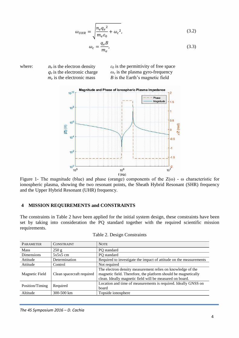
The impedance has a pole at the plasma‟s Upper Hybrid Resonant (UHR) frequency (Figure 1). The
UHR is an ionospheric plasma property dependant on the plasma frequency and its gyro-frequency
(equation 3.2). Therefore the UHR frequency can be used to determine the electron density of the
surrounding ionospheric plasma.
The 4S Symposium 2016 – D. Cachia
4
(3.2)
(3.3)
where: ne is the electron density ε0 is the permittivity of free space
qe is the electronic charge ωc is the plasma gyro-frequency
me is the electronic mass B is the Earth‟s magnetic field
Figure 1- The magnitude (blue) and phase (orange) components of the Z(ω) - ω characteristic for
ionospheric plasma, showing the two resonant points, the Sheath Hybrid Resonant (SHR) frequency
and the Upper Hybrid Resonant (UHR) frequency.
4 MISSION REQUIREMENTS and CONSTRAINTS
The constraints in Table 2 have been applied for the initial system design, these constraints have been
set by taking into consideration the PQ standard together with the required scientific mission
requirements.
Table 2. Design Constraints
PARAMETER CONSTRAINT NOTE
Mass 250 g PQ standard
Dimensions 5x5x5 cm PQ standard
Attitude Determination Required to investigate the impact of attitude on the measurements
Attitude Control Not required
Magnetic Field Clean spacecraft required
The electron density measurement relies on knowledge of the
magnetic field. Therefore, the platform should be magnetically
clean. Ideally magnetic field will be measured on board.
Position/Timing Required Location and time of measurements is required. Ideally GNSS on
board
Altitude 300-500 km Topside ionosphere
The 4S Symposium 2016 – D. Cachia
5
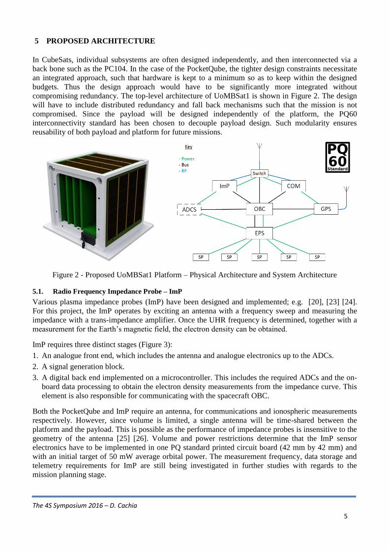
5 PROPOSED ARCHITECTURE
In CubeSats, individual subsystems are often designed independently, and then interconnected via a
back bone such as the PC104. In the case of the PocketQube, the tighter design constraints necessitate
an integrated approach, such that hardware is kept to a minimum so as to keep within the designed
budgets. Thus the design approach would have to be significantly more integrated without
compromising redundancy. The top-level architecture of UoMBSat1 is shown in Figure 2. The design
will have to include distributed redundancy and fall back mechanisms such that the mission is not
compromised. Since the payload will be designed independently of the platform, the PQ60
interconnectivity standard has been chosen to decouple payload design. Such modularity ensures
reusability of both payload and platform for future missions.
Figure 2 - Proposed UoMBSat1 Platform – Physical Architecture and System Architecture
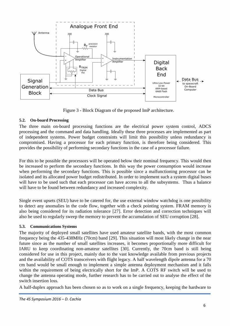
5.1. Radio Frequency Impedance Probe – ImP
Various plasma impedance probes (ImP) have been designed and implemented; e.g. [20], [23] [24].
For this project, the ImP operates by exciting an antenna with a frequency sweep and measuring the
impedance with a trans-impedance amplifier. Once the UHR frequency is determined, together with a
measurement for the Earth‟s magnetic field, the electron density can be obtained.
ImP requires three distinct stages (Figure 3):
1. An analogue front end, which includes the antenna and analogue electronics up to the ADCs.
2. A signal generation block.
3. A digital back end implemented on a microcontroller. This includes the required ADCs and the on-
board data processing to obtain the electron density measurements from the impedance curve. This
element is also responsible for communicating with the spacecraft OBC.
Both the PocketQube and ImP require an antenna, for communications and ionospheric measurements
respectively. However, since volume is limited, a single antenna will be time-shared between the
platform and the payload. This is possible as the performance of impedance probes is insensitive to the
geometry of the antenna [25] [26]. Volume and power restrictions determine that the ImP sensor
electronics have to be implemented in one PQ standard printed circuit board (42 mm by 42 mm) and
with an initial target of 50 mW average orbital power. The measurement frequency, data storage and
telemetry requirements for ImP are still being investigated in further studies with regards to the
mission planning stage.
The 4S Symposium 2016 – D. Cachia
6
Figure 3 - Block Diagram of the proposed ImP architecture.
5.2. On-board Processing
The three main on-board processing functions are the electrical power system control, ADCS
processing and the command and data handling. Ideally these three processes are implemented as part
of independent systems. Power budget constraints will limit this possibility unless redundancy is
compromised. Having a processor for each primary function, is therefore being considered. This
provides the possibility of performing secondary functions in the case of a processor failure.
For this to be possible the processors will be operated below their nominal frequency. This would then
be increased to perform the secondary functions. In this way the power consumption would increase
when performing the secondary functions. This is possible since a malfunctioning processor can be
isolated and its allocated power budget redistributed. In order to implement such a system digital buses
will have to be used such that each processor can have access to all the subsystems. Thus a balance
will have to be found between redundancy and increased complexity.
Single event upsets (SEU) have to be catered for, the use external window watchdog is one possibility
to detect any anomalies in the code flow, together with a check pointing system. FRAM memory is
also being considered for its radiation tolerance [27]. Error detection and correction techniques will
also be used to regularly sweep the memory to prevent the accumulation of SEU corruption [28].
5.3. Communications Systems
The majority of deployed small satellites have used amateur satellite bands, with the most common
frequency being the 435-438MHz (70cm) band [29]. This situation will most likely change in the near
future since as the number of small satellites increases, it becomes proportionally more difficult for
IARU to keep coordinating non-amateur satellites [30]. Currently, the 70cm band is still being
considered for use in this project, mainly due to the vast knowledge available from previous projects
and the availability of COTS transceivers with flight legacy. A half wavelength dipole antenna for a 70
cm band would be small enough to implement a simple antenna deployment mechanism and it falls
within the requirement of being electrically short for the ImP. A COTS RF switch will be used to
change the antenna operating mode, further research has to be carried out to analyse the effect of the
switch insertion loss.
A half-duplex approach has been chosen so as to work on a single frequency, keeping the hardware to
The 4S Symposium 2016 – D. Cachia
7
a minimum. A radio transceiver integrated circuit (IC) is the best solution for such small systems as it
provides all the functionality in the least amount of space.
For a sun synchronous orbit it is assumed that from the 15 orbits per day, the satellite will pass
reasonably overhead twice a day. The satellite contact time will be 6.5 minutes per pass, assuming a
minimum elevation angle of 15º [31]. If half duplex communications is used it is assumed that 75% of
the contact time will be in downlink, and if AX.25 is used then there will be an overhead of 11% [32].
Now assuming that 100 telemetry signals are required with floating point accuracy per orbit and these
are sampled at 16 times per orbit, then the total of 94 KB are required for telemetry. Assuming that the
Payload will require 50 KB as an initial estimate, then a total of 144 KB of data has to be transmitted.
With these assumptions a minimum baud rate of 2000 is required, a baud rate of 2400 is therefore
being assumed.
The Amsat link budget spreadsheet was used to calculate the downlink and uplink budgets [33]. For
the downlink budget if it is assumed that a 0.5W output power is obtained from the transceiver then the
Effective Isotropic Radiated Power (EIRP) will be -2.6dbW. The worst case slant range is 1518Km,
which results in a free space path loss of -148.9dB [34]. A spacecraft antenna pointing loss of -1dB is
also considered and this translates to a lenient pointing accuracy requirement of ±23.6º. If it is assumed
that a circularly polarized antenna is used at the ground station then the worst case polarization
mismatch will be 45º, giving a polarization loss of -3dB [34]. For the ground station a 7 element
crossed Yagi antenna is assumed, having a gain of 13.5dBi. The system link margin was calculated
assuming an FSK modulation scheme and the AX.25 protocol. With a maximum packet size of 332
bytes, and a 1% packet error rate (PER) then a bit error rate (BER) of around 10-6
is required. For the
Uplink budget, the ground station transmission power was taken to be 30W.
For uncoded FSK, the uplink system link margin was calculated to be 10.2dB whilst for downlink this
was just 6dB, when typically a margin of 10db is recommended [35]. For this link margin the baud rate
must be reduced to 1000 Bd. Alternatively forward error correction (FEC) techniques can be used to
increase the link margin by 4dB, so as to achieve the estimated value of 2400 [36].
5.4. Orbital Determination
One of the Payload requirements for Electron Density measurements is to have a measurement of
orbital data, specifically the PQ‟s location. In order to implement this, two possibilities are being
explored, the first one being the use of NORAD Two-Line Element (TLE) sets to obtain orbital
parameters, which would then be used in an orbit propagator. The accuracy achievable using this
approach is in the order of 10-30 km (1) track error and this assuming a propagation of 24 hours. The
error, of course, worsens with longer propagation times [37].
The second option being considered is to use a GNSS receiver to obtain positional information. COTS
receivers designed for terrestrial applications cannot operate in LEO, specifically due to the fact that
the high velocities generate large frequency shifts in the signal, which standard receivers aren‟t
designed to lock onto. Additionally, COTS GNSS receivers are limited in operation due to the
International Traffic in Arms Regulations (ITAR) which limits the maximum velocity (1000kts) and
altitude (60000ft) at which these receivers are allowed to provide a position fix. Along with the above
mentioned difficulties, a GNSS receiver will have an impact on the PQ‟s power budget. In fact,
continuous operation of a GNSS receiver may not be possible within the power constraints. A study is
therefore required on the possibility of periodically using GNSS to obtain orbital parameters, which
would then be used by an adequate orbital propagator to establish an estimate of the PQs position.
The 4S Symposium 2016 – D. Cachia
8
5.5. Attitude Determination System - ADS
As discussed in section 4, ImP electron density measurements may be attitude dependent. However,
the accuracy requirement has not yet been determined. Therefore ±10º has been assumed. The
ESTCube-1 flight results [38] have validated an attitude determination system (ADS) by comparing
measurements to the attitude calculated from the on-board camera image. A peak discrepancy of 1.43º
was found. Whilst this is not a measure of absolute error, it gives an indication of the achievable
accuracies. The ESTCube-1 used a combination of gyroscopic sensors, magnetometers and sun sensors
combined using an Unscented Kalman Filter. This approach has been widely adopted for CubeSat
ADS.
For the PQ, a similar approach will be adopted but regardless of the method used, a magnetometer is
still required for the Imp compensation, and a gyroscopic sensor is needed if active detumbling is to be
performed. In the PQ, some solar cells (1 per face) will also be used for sun sensing. This avoids
dedicated sun sensors at the expense of some ADS accuracy, but saves on PQ surface area.
Another interesting technique for attitude determination is through the use of carrier phase
measurements of GNSS signals across single or multiple antennas [39]. Although this technique has
been successfully tested on large aircraft and small unmanned air vehicles [40], the challenges
associated with small spacecraft at high-speed are very different and must be explored carefully.
5.6. Attitude Control System - ACS
For the purposes of communications and ImP, an attitude control system (ACS) is not strictly
necessary. However, the implications of having one on-board are being investigated nonetheless, as it
would improve the link budget, improve GNSS communications, allow better distribution of solar
radiation on the panels, and reduce radio fading at the expense of complexity and power consumption.
The pointing accuracy requirement is largely defined by the directional antennas used for
communications, and for a dipole antenna this requirement is not particularly stringent. In any case, the
limiting factor of the control algorithm will be the ADS accuracy, so an initial pointing accuracy of 10º
was set as well.
Due to the magnetic cleanliness requirement, traditional passive control techniques such as hysteresis
rods and permanent magnets have to be avoided and gravity booms and solar sails were considered too
mechanically complex to fit in a 1p PQ. So two approaches are being considered:
1. 3MT: 3-axis coreless copper winding magnetorquers (MT) [41], or
2. 3RW+3MT: 3-axis reaction wheels (RW) coupled with smaller MTs for de-saturation [42].
For the PQ, the disturbance torques, in descending order of importance, are of four types:
1. Magnetic Disturbance, due to magnetisation or Lorentz forces created by currents in the PQ
2. Aerodynamic Disturbance, due to residual atmospheric pressure at LEO
3. Gravity Gradient Disturbance, reacting to the uneven distribution of mass in the PQ
4. Solar Radiation Pressure effects, acting unevenly on the faces of the PQ
The above were calculated and compared for a PQ sized object [43] scaled from CubeSats. A worst
case residual magnetic moment of 4.16×10⁻⁴
Am2 has been calculated, yielding a disturbance torque of
2.1×10⁻⁸
Nm, by assuming the largest contribution coming from a badly-designed solar panel current,
looping round the panel‟s perimeter. An aerodynamic disturbance of 1.56×10⁻⁸
Nm, was estimated
from the residual atmosphere at 550km acting on a total incident area of 40cm2 at 7586m/s, at a
moment arm taken at 1/3 the size of the 70cm band antennas. Gravity gradient and solar pressure
effects were deemed negligible at 9.0×10⁻¹⁰
Nm and 4.1×10⁻¹⁰
Nm respectively.
The 4S Symposium 2016 – D. Cachia
9
A 3MT solution is the most magnetically clean, given that these would only be energised when ImP is
inactive. However, the actuation would be rank deficient since the coil whose axis is parallel to the
earth‟s magnetic field cannot produce any torque, and any coil close to parallel would need to be
substantially overdriven to generate any useful torque. This means that reliance on just magnetorquers
requires them to be sized and rated to provide at least 10 times the dominant disturbance torque. This
results in large and heavy coils that consume substantial power.
The alternative method of actuation is to use the 3RW+3MT setup, based on DC micro-motors and
smaller MT coils. This allows the MT to be opportunistically activated only when the B-field is at
~ 90º to the coil axis, which lends itself for much greater power and mass efficiency. The RWs also
lend themselves for simpler and more accurate control.
The problem here is that the motors carry a tiny annular NdFeB permanent magnet which although
screened with a mild steel canister, does leak some flux. The measured magnetic flux density at the
motor surfaces is quite low and comparable to the geomagnetic flux (~50uT), but it has yet to be seen
to what extent this will distort the field in proximity to the ImP antenna. That said, removal of all
magnetic disturbances will be impossible, because even the current in the panels and the batteries will
generate some disturbance. Therefore, some method of compensation would have to be devised
anyway.
Finally, a viscous damper consisting of a hermetically sealed fluid-filled chamber is additionally being
considered as a passive de-tumbling / de-oscillating system of last resort. However, this needs to be
modelled and would in any case only work if there is oscillatory motion, due to gravity gradient
effects. For this, the PQ‟s centre of mass would need to be significantly off centre [44].
5.7. Electrical Power System – EPS
For a PQ a reasonable solar cell area will be 6 sides with 16 cm2 of active area and cells being
considered are 28% efficient triple junction solar cells. The worst case sun synchronous orbit in terms
of power is when the Sun is in the orbital plane (midnight/noon), since the PQ will have the longest
shadow time [45]. With these parameters the PQ will have an orbit time of 96 minutes with a shadow
time of 37%, assuming a Nadir pointing design [46], the average orbit power available is 300mW,
when considering typical efficiencies of the Electrical Power System.
In order to achieve this estimate, the EPS must make use of Maximum Power Point (MPPT) tracking.
An integrated chip solution is being considered as the most viable approach. Another concern when
assuming 300mW is the solar cell degradation, for bare cells the End of Life(EOL) was predicted to
be 42% for bare TASC cells whilst Spectrolab UTJ cells with cover glass were estimated to have an
EL of 92% after two years [47].
The EPS is also responsible for Energy storage, the most common approach in CubeSats has been the
use of Lithium-ion polymer batteries (Li-Po). Their disadvantage is the narrow temperature operating
region and the limited number of charge/discharge cycles as well as the possibility of capacity
degradation under vacuum, if these are not physically restrained [48]. In order to increase the number
of charge/discharge cycles it is recommended to keep the depth of discharge (DOD) and
charge/discharge rates to a minimum [7]. It is estimated that with a DOD of 30% the Li-Po will have a
loss of capacity of 50% over one year [7] [49]. The worst case depth of discharge will occur when the
transmitter is active during eclipse time. Assuming a 500mW output RF power for the communications
and a 30% efficiency (estimate from commercial transmitters) [50] then 1.66W is required for 6.5
The 4S Symposium 2016 – D. Cachia
10
minutes, and assuming that an additional average of 200 mW is being consumed throughout the eclipse
time, then a 1000mAH battery will have a DOD of 8%.
Since the energy storage is the limiting factor to a mission‟s lifetime, super capacitors will be
considered as a secondary storage so that when the Li-Po degrades, the mission can continue at a
reduced performance. Super capacitors have the advantage of being less sensitive to charging cycles
and temperature. They have higher power densities, but they also have a smaller energy density.
The EPS design has to focus on the design of switchable supplies for power distribution and circuit
protection such that sub systems are protected from single event latch-ups (SEL). The use of
switchable supplies is necessary so that subsystems can be powered down and isolated if needed.
Additionally telemetry will be collected to examine the performance of the EPS as well as the solar
cell and battery degradation.
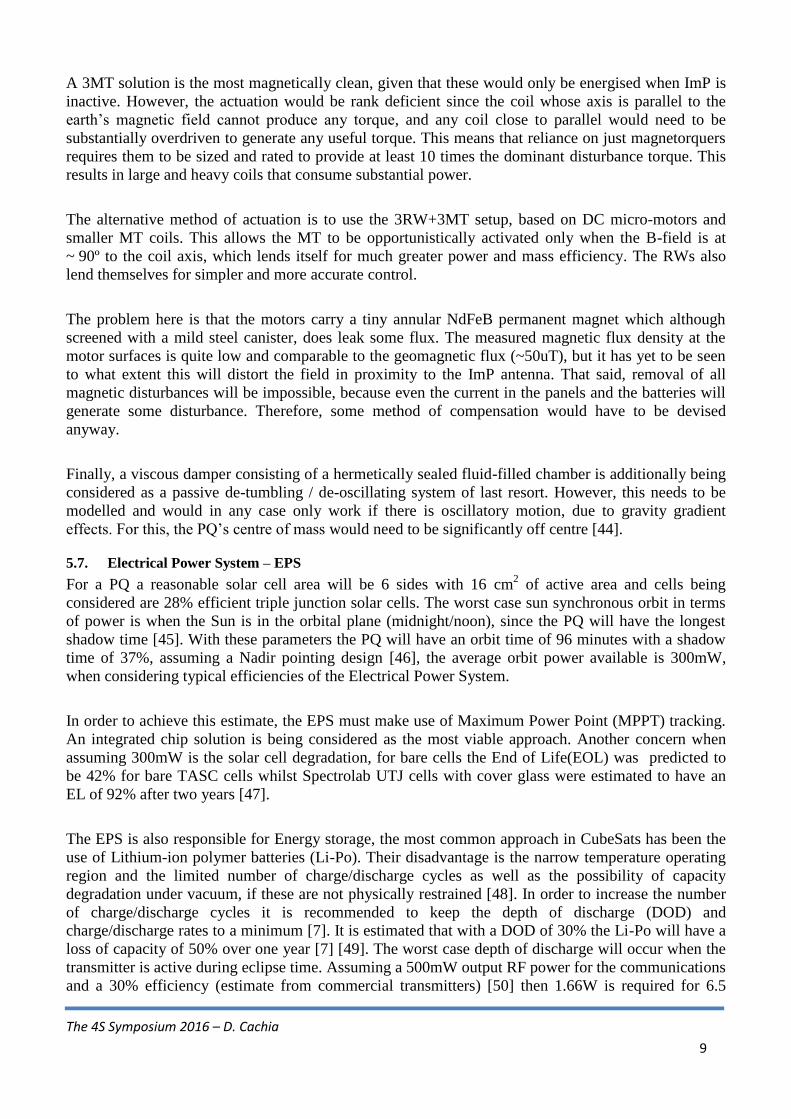
5.8. The Power Budget
For the Power Budget to be met, operations have to be scheduled such that the average orbital power is
kept to a minimum whilst ensuring that each subsystem‟s power peak occurs at different times to keep
the battery DOD as low as possible. Table 3 shows the preliminary power budget, with estimates as
discussed throughout the paper, a 25% margin has been set to cater for any parameters that may not
have been factored in.
Table 3 - Preliminary power budget
SUB-
SYSTEMS COMPONENTS
ORBIT TIME
[%]
FREQUENCY
[PER DAY]
POWER
INSTANTANEOUS
[mW]
PEAK
[mW]
ORBITAL
AVERAGE [mW]
EPS EPS processor* Continuous n/a 10 10 101
COMMS
Operation(Beacon) 10% Each orbit 100
1666
102
Operation (TX) 7% 2 1666 15
Operation(RX) Continuous n/a 60 60
ADCS
3RW+3MT TBD Each orbit 25
TBD
253
ADS TBD Each orbit 30 154
ADCS Processor* TBD Each orbit 10 105
GNSS GNSS Module Whole orbit 2 120 120 166
OBC* μController Continuous n/a 15 15 15
ImP μController TBD TBD TBD TBD 50
Total: 226
*processors assumed to be identical, power consumption assumes processors are put in low power
modes when not in use.
1. The EPS power assumes a processor with lower operating frequency
2. The beacon is assumed to have 13dBm output power, at 100bps CW
3. Initially allocated budget for a tentative ACS, for worst case 100% duty.
4. Attitude determination assuming 2 gyroscopic sensors and 2 magnetometers
5. Initially allocated budget for ADCS processor, for worst case 100% duty.
6. Power consumption from commercially available GNSS module
The 4S Symposium 2016 – D. Cachia
11
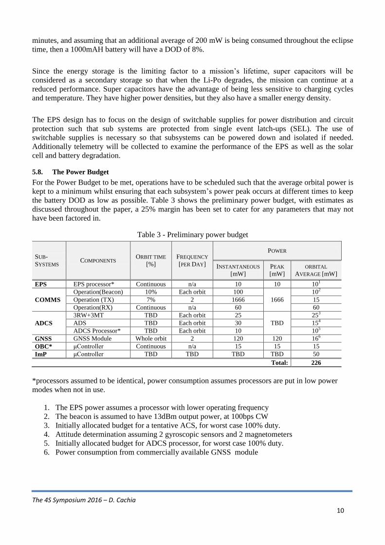
5.9. The Mass Budget
With the design criteria discussed in this paper, an initial mass budget has been allocated as shown in
Table 4, keeping within the 250g limit. In order to work within this budget, 1mm or thinner PCBs have
to be considered and a chassis will be designed so as to reduce the mass to a minimum. It has yet to be
established whether the remaining budget will be sufficient for an eventual ACS.
Table 4 - Estimate of Mass Budget
SUBSYSTEM COMPONENTS MASS
[g]
MASS
[g] NOTES
Structure
AL7075 chassis 25
95.7
Custom designed and chassis machined in-house
PCB‟s 62 Assuming 5 PCBs and 6 PCBs for solar cell faces, 1mm thick
Connectors 5.7 Data Connectors, RF Connectors
Fasteners 3 Screws or latches
EPS
Solar cells 11.2
33.2
Triple Junction cells, 16cm2 per face including cover glass
Battery 17 Measured for a typical 1000mAH Li-Po
EPS components 5 MPPT, Processor, Sundry passives
COMMS RF Components 5
7.3 Transceiver, RF Amplifier, RF switch
Antenna 2.3 Beryllium Copper antenna sections of 175 × 0.8 × 0.1mm
GNSS GNSS Module 10 10 Module includes GNSS receiver and patch antenna
ADCS
3RW+3MT
Magnetorquers 8.1
93.8
Assuming 3 magnetorquers of 2.7g each for RW de-spinning
Motors 4.8 Assuming 3 DC micro motors of 1.6g each
Reaction Wheels 24.6 Assuming 3 reaction wheels of 8.2g each
Drivers, Sensors 5 Accelerometer, Gyroscope, Magnetometer, 3 Axis
Contingency 51.3 Any un-utilised mass budget may be distributed elsewhere.
OBC Microcontroller 5 5 Including voltage supervisor, watchdog, external memory
ImP μController 2
5 Including voltage supervisor, watchdog
Analogue 3 Acquisition signal chain
Total: 250.0
5.10. Operational Aspects
The initial operational model adopted plans to use two ground stations, one in Malta and another in
Birmingham. However, since these two locations are relatively close, this doesn‟t provide a significant
advantage over a single station. An alternative, is to engage the amateur radio community to widen the
ground station network which could be set up for data access. For this, the beacon could be used to
broadcast the more important data. If necessary, the main transceiver could be scheduled for more
frequent data transmissions at the cost of reducing the transmission power and data rates.
As for command telemetry and data analysis, two teams would have to be set up. One team would be
responsible for the platform commands and data analysis such as battery voltage, and general system
health, so that any faults can be simulated on the flight spares. Commands can then be uplinked to the
PQ to modify its behaviour. The second team would be responsible for the scientific mission
operations, including payload faults, ImP calibration, and analysis of the collected scientific data.
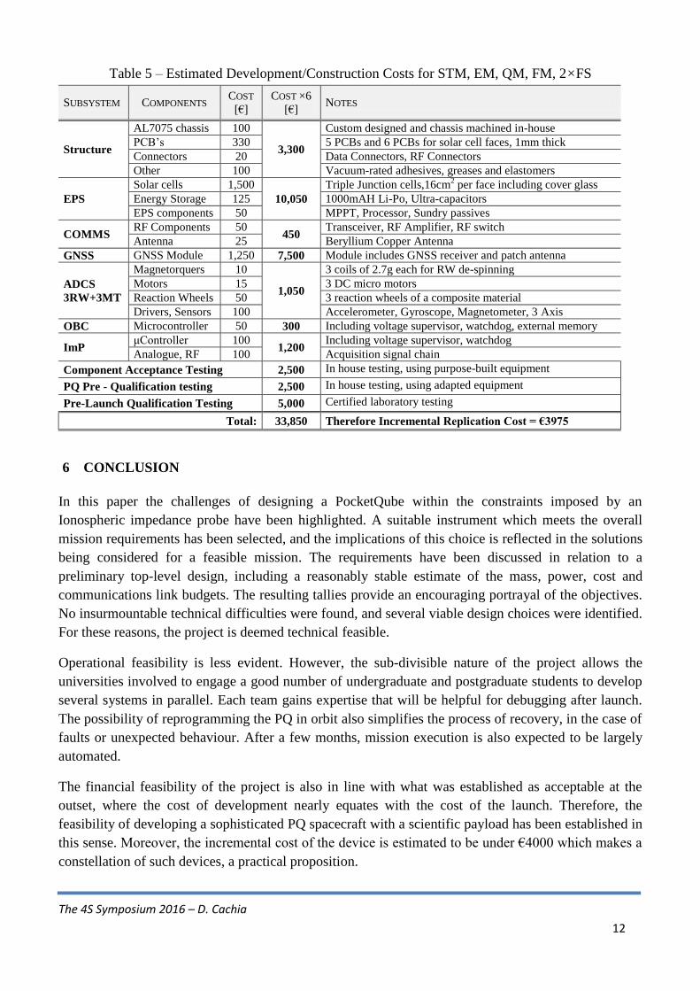
5.11. The Cost Budget
Development of one-off, high-value devices such as satellites undergoes several phases and several
complete systems are built throughout the process. These models are typically termed as follows:
Structural and Thermal (STM), Engineering (EM), Qualification (QM), Flight (FM), at least 2x Flight
Spares (FS). This means that the development costs must include the development of around 6
complete spacecraft. Although the testing aspects do not contribute the cost of construction of each
device, these have been included in the overall development cost figure as shown in Table 5.
The 4S Symposium 2016 – D. Cachia
12
Table 5 – Estimated Development/Construction Costs for STM, EM, QM, FM, 2×FS
SUBSYSTEM COMPONENTS COST
[€]
COST ×6
[€] NOTES
Structure
AL7075 chassis 100
3,300
Custom designed and chassis machined in-house
PCB‟s 330 5 PCBs and 6 PCBs for solar cell faces, 1mm thick
Connectors 20 Data Connectors, RF Connectors
Other 100 Vacuum-rated adhesives, greases and elastomers
EPS
Solar cells 1,500
10,050
Triple Junction cells,16cm2 per face including cover glass
Energy Storage 125 1000mAH Li-Po, Ultra-capacitors
EPS components 50 MPPT, Processor, Sundry passives
COMMS RF Components 50
450 Transceiver, RF Amplifier, RF switch
Antenna 25 Beryllium Copper Antenna
GNSS GNSS Module 1,250 7,500 Module includes GNSS receiver and patch antenna
ADCS
3RW+3MT
Magnetorquers 10
1,050
3 coils of 2.7g each for RW de-spinning
Motors 15 3 DC micro motors
Reaction Wheels 50 3 reaction wheels of a composite material
Drivers, Sensors 100 Accelerometer, Gyroscope, Magnetometer, 3 Axis
OBC Microcontroller 50 300 Including voltage supervisor, watchdog, external memory
ImP μController 100
1,200 Including voltage supervisor, watchdog
Analogue, RF 100 Acquisition signal chain
Component Acceptance Testing 2,500 In house testing, using purpose-built equipment
PQ Pre - Qualification testing 2,500 In house testing, using adapted equipment
Pre-Launch Qualification Testing 5,000 Certified laboratory testing
Total: 33,850 Therefore Incremental Replication Cost = €3975
6 CONCLUSION
In this paper the challenges of designing a PocketQube within the constraints imposed by an
Ionospheric impedance probe have been highlighted. A suitable instrument which meets the overall
mission requirements has been selected, and the implications of this choice is reflected in the solutions
being considered for a feasible mission. The requirements have been discussed in relation to a
preliminary top-level design, including a reasonably stable estimate of the mass, power, cost and
communications link budgets. The resulting tallies provide an encouraging portrayal of the objectives.
No insurmountable technical difficulties were found, and several viable design choices were identified.
For these reasons, the project is deemed technical feasible.
Operational feasibility is less evident. However, the sub-divisible nature of the project allows the
universities involved to engage a good number of undergraduate and postgraduate students to develop
several systems in parallel. Each team gains expertise that will be helpful for debugging after launch.
The possibility of reprogramming the PQ in orbit also simplifies the process of recovery, in the case of
faults or unexpected behaviour. After a few months, mission execution is also expected to be largely
automated.
The financial feasibility of the project is also in line with what was established as acceptable at the
outset, where the cost of development nearly equates with the cost of the launch. Therefore, the
feasibility of developing a sophisticated PQ spacecraft with a scientific payload has been established in
this sense. Moreover, the incremental cost of the device is estimated to be under €4000 which makes a
constellation of such devices, a practical proposition.
The 4S Symposium 2016 – D. Cachia
13
7 REFERENCES
[1] E. Kulu, “The Nanosatallite Database,” Radius Space, [Online]. Available:
http://www.nanosats.eu. [Accessed 19 04 2016].
[2] C. Boshuizen, J. Mason, P. Klupar and S. Spanhake, “Results from the Planet Labs Flock
constellation,” in The 28th Annual AIAA/USU Conference on Small Satellites, American Institute
of Aeronautics and Astronautics (AIAA), Logan, UT, 2014.
[3] Interorbital Systems, TubeSat Kit Specifications and Pricing, 2.0 ed., 2013.
[4] R. J. Twigs, J. G. Jernigan, L. R. Cominsky, B. K. Malphrus, B. S. Silverman, K. Zack, S.
McNeil, W. Roack-Barrett and T.-L. Team, “The PocketQube Concept,” in Cubesat Workshop,
California State Polytechnic University, 2014.
[5] M. Mercedes, W. Andrew, C. Aman and T. Jekan, SunCube FemtoSat Design Specifications
(SFDS), Arizona State University, 2016.
[6] D. J. Barnhart, T. Vladimirova and M. S. Sweeting, “Satellite-on-a-Chip: A Feasibility Study,” in
Proc. 5th Round Table on Micro/Nano Technologies for Space, Nordwijk, The Netherlands, 2005.
[7] C. Clark and E. Simon, “Evaluation of Lithium Polymer Technology for Small Satellite,” in
Proceedings of the 21st Annual AIAA/USU Conference on Small Satellites, Logan, Utah, USA,
2007.
[8] S. M. Guertin, “CubeSat and Mobile Processors,” in NASA Electronics Technology Workshop,
NASA Goddard Space Flight Center in Greenbelt, MD, June 23-26, 2015..
[9] S. Gregucci, Pannelli fotovoltaici a basso costo per piccoli satelliti: progettazione, sviluppo e
qualifica per applicazione su UniSat5, Pisa: Universita‟ Degli Studi di Pisa , 2012.
[10] SSE group, “Small satellite projects and their cost,” Delft University of Technology, [Online].
Available: http://www.lr.tudelft.nl/en/organisation/departments/space-engineering/space-systems-
engineering/expertise-areas/mission-concept-exploration/small-satellite-projects/. [Accessed 25
April 2016].
[11] National Space Weather Program, Washington DC, 1995.
[12] T. F. Tascione, Introduction to the Space Environment, 2nd ed., Malabar, Florida: Krieger
Publishing Company, 1994.
[13] K. Davies, Ionospheric Radio, 1st ed., London: The Institution of Engineering and Tech., 1990.
[14] R. A. Anthes, “Exploring Earth's atmosphere with radio occultation: contributions to weather,
climate and space weather,” Atmospheric Measurement Tech., no. 4, pp. 1077-1103, 2011.
[15] C. G. Carlson, “Next Generation Plasma Frequency Probe Instrumentation Technique,”
American Geophysical Union, 2003.
[16] E. A. Spencer, S. Patra, T. Andriyas, C. M. Swenson and J. Ward, “Plasma Impedance Probe
Analysis with a Finite Difference Time Domain Simulation,” in 16th IEEE International Pulsed
Power Conference, 2007.
The 4S Symposium 2016 – D. Cachia
14
[17] D. Blackwell, D. N. Walker and W. E. Amatucci, “Measurement of Absolute Electron Density
with a Plasma Impedance Probe,” Review of Scientific Instruments, vol. 76, no. 2, pp. 1-7, 2005.
[18] M. Ya-li, T. Fu-jun, X. Yu-xiong, C. Yi-feng and G. Xin, “Retarding Potential Analyzer Design
and Result Analysis for Ion Energy Distribution Measurement of the Thruster Plume in the
Laboratory,” International Journal of Mechanical, Aerospace, Industrial, Mechatronic and
Manufacturing Engineering , vol. 6, no. 11, pp. 1825-1828, 2012.
[19] P. C. Neal, N. D. Taormina and A. R. Strom, “iMESA-R : An Integrated , Miniaturized ,
Electrostatic Analyzer - Reflight,” in 31st Space Symposium, Technical Track, Colorado Springs,
Colorado, United States of America, 2015.
[20] A. Barjatya, Langmuir Probe Measurements in the Ionosphere, Utah State University, 2007.
[21] A. C. Escobar, A Langmuir Probe Instrument For Research In The Terrestrial Ionosphere,
Pennsylvania State University, 2009.
[22] G. S. Jiang, W. H. Chen, Y. W. Hsu, K. Oyama and C. Z. Cheng, “Development of Electron
Temperature and Density Probe (TeNeP) for Nano- and Micro-satellites-II,” in Japan Geoscience
Union Meeting, Pacifico, Yokohoma, 2014.
[23] M. Jayaram, M. A. E. Hamoui, S. Patra, C. Winstead and E. Spencer, “Fully-Integrated
Electronic System for a Plasma Impedance Probe,” in AIAA/USU Conference on Small Satellites,
2008.
[24] M. A. E. Hamoui, A Pipeline Analog-To-Digital Converter for a Plasma Impedance Probe, Utah
State University, 2009.
[25] P. Nikitin and C. Swenson, “Impedance of a Short Dipole Antenna in a Cold Plasma,” IEEE
Trans. Antennas Propag., vol. 49, no. 10, pp. 1377-1381, 2001.
[26] K. G. Balmain, “The Impedance of a Short Dipole Antenna in a Magnetoplasma,” IEEE Trans.
Antennas Propag., vol. 12, no. 5, pp. 605-617, 1964.
[27] C. Sansoè and M. Tranchero, “Use of FRAM Memories in Spacecrafts,” in Ferroelectrics -
Applications, InTech, 2011, pp. 213-230.
[28] K. A. Ødegaard, Error Detection and Correction for Low-Cost Nano Satellites, Norwegian
University of Science and Technology, 2013.
[29] B. Klofas and K. Leveque, “A Survey of CubeSat Communication Systems: 2009-2012,” in 10th
Annual CubeSat Developers Workshop, Cal Poly State University, San Luis Obispo, CA , 2013.
[30] B. Price, Amateur Radio’s View on CubeSat Spectrum and Licensing Issues, ARRL, 2015.
[31] E. Narverud, Design of a UHF Radio System for Small LEO Satellites, Norwegian University of
Science and Technology, 2007.
[32] B. L. E. Mendez, Link Budget for NTNU Test Satellite, Norwegian University of Science and
Technology, 2013.
[33] J. A. King, AMSAT / IARU Standard Link Budget System, 2003.
[34] G. Maral and M. Bousquet, Satellite Communication System, Wiley, 2009.
The 4S Symposium 2016 – D. Cachia
15
[35] J. L. Tresvig, Design of a Prototype Communication System for the CubeSTAR Nano-satellite,
University of Oslo, 2010.
[36] K. D. VEA and P. S. Storvik, Ground Station Based on Software Defined Radio, Norwegian
University of Science and Technology, 2014.
[37] K. Riesing, “Orbit Determination from Two Line Element Sets of ISS-Deployed CubeSats,” in
29th Annual AIAA/USU Conference on Small Satellites, 2015.
[38] A. Slavinskis, H. Ehrpais, H. Kuuste, I. Sünter, J. Viru, J. Kütt, E. Kulu and M. Noorma, “Flight
Results of ESTCube-1 Attitude Determination System,” Journal of Aerospace Engineering, vol.
29, no. 1, 2016.
[39] V. Capuano, C. Botteron and P. A. Farine, “GNSS Based Attitude Determination Systems for
Nanosatellites,” in In Adv. in the Astronautical Sciences (No. EPFL-CONF-198745), 2014.
[40] R. Sabatini, L. Rodriguez, A. Kaharkar, C. Bartel and T. Shaid, “Carrier-phase GNSS Attitude
Determi- nation and Control System for Unmanned Aerial Vehicle Applications,” ARPN Journal
of Systems and Software, vol. 2, no. 11, 2012.
[41] G. Bråthen, Design of Attitude Control System of a Double CubeSat, Norwegian University of
Science and Technology, 2013.
[42] J. F. Trégouët, D. Arzelier, D. Peaucelle, C. Pittet and L. Zaccarian, “Reaction wheels
desaturation using magnetorquers and static input allocation,” Control Systems Technology,
IEEE Transactions on, vol. 23, no. 2, pp. 525-539, 2015.
[43] F. Stray, Attitude Control of a Nano Satellite, University of Oslo, 2010.
[44] K. T. Alfkiend, “Analysis of the Partially Filled Viscous Ring Damper, Final Report, NASA Grant
NGR-33-010-169,” Cornell Unfversity , Ithaca, New York, October 1973.
[45] C. Dopart, D. Morlath, E. Oliver and J. Schomaker, Design and Analysis for a Cubesat Mission,
Worcester Polytechnic Institute, 2012.
[46] S. Sanchez-Sanjuan, J. Gonzalez-Llorente and R. Hurtado-Velasco, “Comparison of the Incident
Solar Energy and Battery Storage in a 3U CubeSat Satellite for Different Orientation Scenarios,”
J. Aerosp. Technol. Manag., vol. 8, no. 1, p. 91–102, 2016.
[47] A. I. L. Telgie, Design and analysis of the DelFFi solar energy supply, Delft University of
Technology, 2014.
[48] J. A. Jeevarajan and B. E. Duffield, “Performance and Safety oF Lithium-Ion Polymer Pouch
Cells,” Journal of Space Safety Engineering, vol. 1, no. 1, pp. 10-16, 2014.
[49] N. Navarathinam, R. Lee and H. Chesser, “Characterization of Lithium-Polymer batteries for
CubeSat applications,” Acta Astronautica, vol. vol. 68, no. no. 11-12, pp. 1752-1760, 2011.
[50] J. Kalde, “UHF Communication System for Cubesatellite,” University of Tartu, Estonia, 2015.