Embed Size (px)
Citation preview

CYCLIC TESTING OF PULTRUOEO F m E R - R E I N F O R C E O PLASTIC BEAM-COLUMN RIGID CONNECTION
By Michel Bruneau, 1 Member, ASCE, and David Walker z
ABSTRACT: This paper reports on the following: (1) Simple experimental inves- tigations of pultruded fiber-reinforced plastic (PFRP) material behavior and tests of simple epoxied joints to verify and enhance the reported database; (2) cyclic tests of an attempted PFRP rigid beam-column connections; and (3) preliminary observations regarding the seismic-resistance worthiness of PFRP structures. These are simple design issues that must be addressed if PFRP structural shapes are to gain broad acceptance by the design community. It is found that epoxied connec- tions alone cannot fully exploit the high-strength potential of this material, and that delamination of components is more problematic than the inherent brittleness of the material. The cyclic flexural test of an attempted rigid beam-column con nection has revealed the particular delamination weakness of the flange-to-web core of PFRP structural shapes. The construction of rigid beam-column connections using commonly used steel details is found to be ineffective.
INTRODUCTION
To this day, the use of pultruded fiber-reinforced plastic (PFRP) in struc- tural engineering has been rather limited compared to the use of steel and concrete, and it is still mostly confined to specialty applications where resis- tance to highly corrosive environments, electromagnetic transparency, or a low weight-to-strength ratio is required. However, this industry is growing very rapidly, and the need for conventional design guidelines is already being felt. Yet, many technical/practical detail-oriented questions remain unanswered. This effectively delays the broad acceptance of PFRP structural shapes by the design community.
Although ASCE has published manuals on selection and design of struc- tural plastics ("Structural" 1984, 1985), the industry has recently evolved considerably. Moreover, that body of information is not necessarily directly applicable for the design of PFRP structures by the average practicing en- gineer experienced with more traditional materials.
For example, the seismic performance of PFRP frames remains unknown. As earthquake-resistant design requirements are becoming mandatory in a progressively larger number of jurisdictions (and have already been in place throughout Canada for over 15 years), PFRP frames are increasingly likely to be constructed in such regions. Most current seismic codes have adopted a static-equivalent design force equation that includes a strength-reduction factor to account for the potential cyclic ductile characteristics of various materials and construction types, and banned brittle constructions from regions exposed to moderate and severe seismic risk. Hence, there is an urgent need for more research on the seismic worthiness of PFRP structures.
In this perspective, the present paper reports on the following: (1) Simple
1Assoc. Prof., Dept. of Civ. Engrg., 161 Louis Pasteur, Univ. of Ottawa, Ontario, Canada, K1N 6N5.
~Res. Asst., Dept. of Civ. Engrg., 161 Louis Pasteur, Univ. of Ottawa, Ontario, Canada K1N 6N5.
Note. Discussion open until February l , 1995. To extend the closing date one month, a written request must be filed with the ASCE Manager of Journals. The manuscript for this paper was submitted for review and possible publication on January 6, 1993. This paper is part of the Journal of Structural Engineering, Vol. 120, No. 9, September, 1994. �9 ISSN 0733-9445/94/0009-2637/$2.00 + $.25 per page. Paper No. 5314.
2637

experimental investigations of PFRP material behavior and tests of simple epoxy joints to verify and enhance the reported database; (2) cyclic tests of an attempted PFRP rigid beam-column connection; and (3) preliminary observations regarding the seismic-resistance worthiness of PRFP structures. These are simple design issues that must first be resolved before approaching the seismic-performance problems.
It is noteworthy that another objective of the present study is to assess whether a structural engineer experienced in the design of conventional steel structures ("Handbook" 1991; Manual 1986) can apply his knowledge to successfully design PFRP shapes and, more importantly, their connec- tions.
TEST OF MATERIAL AND COMPONENTS
There appears to be, at this time, no design codes concerned exclusively with the behavior and performance of PFRP structural shapes. Compared to other traditional engineering materials, the structure and properties of advanced composite materials vary greatly and are still, to a large extent, manufacturer dependent. Tests of material and components are essential.
The PFRP structural shapes used for this limited-scope testing program were manufactured by the Morrison Molded Fiberglass Company, Bristol, Va., under the EXTREN 500 material designation. They are of continuous- strand fiberglass roving and isophthalic polyester resin. Compliance to the design and practical recommendations made by manufacturers of PFRP products (MMFG 1989; Creative 1988) was achieved whenever possible throughout this project.
Material A recent report on engineering practice ("Structural" 1984, chapter 3)
and a state-of-the-art report on advanced composite materials in bridges and structures (Mufty et al. 1991) indicate that reinforced plastics generally behave linear-elastically up to a failure. Nonetheless, it was felt worthwhile to test ASTM E-08 type coupons to determine the actual ultimate perfor- mance and capacity of this EXTREN material and to photographically doc- ument the failure mode of typical specimens. This latter, visual information was not found in the available literature.
Two coupons were prepared in accordance with the ASTM E-08 speci- fication with a 7-in. gage length. In both cases, a 484 mm 2 (0.75 sq in.) cross section was tested. Observed behavior was essentially linear-elastic with very slight nonlinearity prior to rupture. The specimens reached an average ultimate stress of 151.9 MPa (22 ksi) and 140.5 MPa (20.4 ksi), less than the theoretical ultimate stress of 207 MPa (30 ksi) quoted in the MMFG (1989). However, stress-concentration factors cannot be ignored in brittle materials such as PFRP. These were calculated to be approximately 1.6 for the ASTM coupons tested, which brings the maximum local stresses to 243 MPa (35.2 ksi) and 225 MPa (32.6 ksi), slightly above the theoretical value. The experimentally obtained modulus of elasticity was 17,900 MPa (2,600 ksi), i.e., practically equal to that of 17,250 MPa (2,500 ksi) suggested in MMFG.
It is noteworthy that the coupons were cut from fiat-sheet products in what was believed to be the length-wise direction, that is, parallel to the longer dimension of the fiat sheet. However, in absence of visual markings specifying orientation of fibers in a flat PFRP sheet, a risk exists that material
2638
could be mistakenly cut out in the crosswise direction. Since the theoretical crosswise ultimate stress of this EXTREN flat-sheet product is only 60% of the lengthwise direction [i.e., 124 MPa (18 ksi)], the use of directional markings in such an anisotropic material is highly recommended.
Failure of the tension specimen occurred suddenly, in a very jagged and irregular pattern of ruptured fibers. This resulting fibrous failure surface somewhat resembles that of wood product in tension tests parallel to grain, as illustrated in Fig. 1.
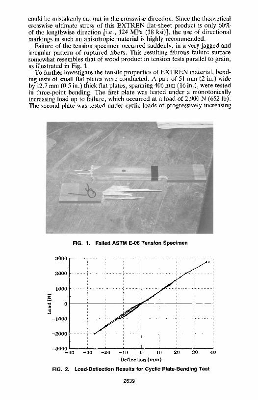
To further investigate the tensile properties of EXTREN material, bend- ing tests of small flat plates were conducted. A pair of 51 mm (2 in.) wide by 12.7 mm (0.5 in.) thick flat plates, spanning 406 mm (16 in.), were tested in three-point bending. The first plate was tested under a monotonically increasing load up to failure, which occurred at a load of 2,900 N (652 lb). The second plate was tested under cyclic loads of progressively increasing
FIG. 1. Failed ASTM E-06 Tension Specimen
3000
2000
-2000
-3000 - 4 0 - 3 0 - 2 0 - 1 0 0 10 20 30 40
D e f l e c t i o n ( r a m )
FIG. 2. Load-Deflection Results for Cyclic Plate-Bending Test
IOOO z
o 0
-1000
2639

intensity. The resulting load-deflection curve is shown in Fig. 2. This plate failed during the fourth cycle of loading, with behavior remaining essentially elastic all along. The ultimate load reached was 2,749 N (618 lb) at a max- imum deflection of roughly 40 mm (1.6 in.). These loads correspond to stresses of 215 MPa (31.3 ksi) and 204.8 MPa (29.7 ksi), respectively, which compare favorably with the theoretical ultimate bending stress of 206.8 MPa (30 ksi) recommended in MMFG (1989). Low-cycle fatigue strength was not investigated.
The deflected shape of one plate near failure is shown in Fig. 3. This eloquently illustrates the phenomenal flexibility of this advanced composite material. It is noteworthy that considerable attention must be paid by struc- tural engineers to deflection-related problems when designing PFRP struc- tures. However, the design philosophy and implementation for given proj- ects could be steered to advantageously rely on these very large deformations as a warning against incipient collapse, somewhat compensating for the lack of such warnings from the inherent brittleness of this PFRP material.
Components The detailing of connections for PFRP shapes is somewhat problematic.
The material can be neither bent, rolled, nor pressed as can be other metal shapes and materials. Hence, manufacturers tend to recommend adhesive joint connections. In this particular case, MMFG (1989) recommends Shell 828 Epoxy Resin, Dow D.E.R. 331 Epoxy Resin, or MMFG Epoxy Ad- hesive. In general, epoxy adhesives provide stronger joints than polyester adhesives.
Guidelines on the proper preparation of surfaces and joint curing must be followed closely. Mating surfaces must be sanded with 120 grit sandpaper to remove the glossy surface, and the surfacing veil must be ground off to expose the reinforcement mat. Contaminated surfaces must be thoroughly cleansed by wiping with a clean rag dampened with a solvent. In this case, acetone was used. Equal volumes of base and hardener are mixed, and a uniform thin coat is spread on one of the surfaces to be bonded. Freshly bonded joints should be held with clamps or weights for at least 8 h until
FIG. 3. Plate's Flexural Deformations near Failure
2640

they can be handled carefully. The joint should not be expected to carry its design load until it has cured a minimum of 48 h.
Generally, little is reported in the available literature on the ultimate behavior of epoxies recommended by manufacturers of PFRP shapes. To acquire this information, three small PFRP specimens were bonded together with epoxy and tested to rupture. All three failed suddenly and without warning. Experimentally obtained tensile capacities for the epoxy were 23 MPa (3.35 ksi), 20.9 MPa (3.03 ksi), and 15.2 MPa (2.20 ksi) for each of the specimens, respectively. This is an order of magnitude lower than the ultimate strength of the material. Clearly, epoxy connections are a rather weak and brittle structural link and epoxied-only joints could prevent ef- ficient use of PFRP material at its full capacity.
The epoxy's approximate ultimate shear was experimentally obtained from nonstandard specimens consisting of two narrow 25 mm (1 in.) wide by 12.5 mm (0.5 in.) thick by 200 mm (8 in.) long plates bonded symmet- rically along a 25 mm (1 in.) overlap to two wider plates, and inserted into the grips of a universal testing machine. The results of one such shear test are shown in Fig. 4. Elongation was measured arbitrarily between two reference points on the larger plates until rupture on any of the two shear surfaces. Shear stresses of approximately 8.9 MPa (1.3 ksi) were obtained in each case. In spite of the large eccentricity introduced in each specimen following first failure, the remaining single shear surface was able to with- stand a much larger shear stress. In both cases, the ultimate capacity of this remaining eccentric single shear surface reached 11.9 MPa (1.73 ksi). A typical failed specimen is shown in Fig. 5.
Finally, epoxy peel strength was investigated. Four 75 mm (3 in.) equal- legs angles, 9.5 mm (0.375 in.) thick and 50 mm (2 in.) wide, were bonded together back-to-back to form a star-shaped cross section. The two un- bonded legs of this shape were fixed into the grips of the universal testing machine, the bonded surface being tested in tension.
Two specimens were tested. For the first specimen, the epoxy ruptured brittly on one leg of the shape at a load of 6,984 N (1.57 kips), corresponding to an ultimate unit peel strength of 138 N/ram (787 lb/in.) and triggered progressive delamination of the remaining leg. Capacity dropped to 26 N/mm (150 ib/in.) as delamination progressed, and separation occurred at
8000
" ~ 6 0 0 0
0
12000 . . . . . . . . . . . . . . . . . . . . . . . . . . . . . . . . . . . . . . . . . . . . . . . . . . . . . . . . . . . . . . . . . . . . . . . . . . : . . . . . . . . . . . .
1 0 0 0 0
4000
2000
0 ~ i
0 1 2 3 4 5 6
E longat ion (ram)
FIG. 4. Stress-Deformation of Epoxy Shear-Test Specimens
2 6 4 1

FIG. 5. Failed Epoxy Shear-Test Specimen
very large deformations. The second specimen behaved somewhat better, as no brittle peeling separation occurred. Instead, cleavage initiated simul- taneously on both legs of the shape, with delamination of the PFRP angles starting at a load of 9,118 N (2.05 kips). The subsequent rapid drop in strength leveled to a plateau of sustained delamination strength until very large deformations and rupture occurred. By inference, unit peel strength exceeded 179 N/mm (1,023 lb/in.). Results and a partly failed specimen are shown in Figs. 6 and 7, respectively.
These component tests demonstrate the difficulty in designing efficient PFRP structures if relying purely on adhesive connections of overall low strength.
DESIGN OF PFRP BEAM-COLUMN RIGID CONNECTION
Based on the aforementioned test results for simple components and material, an attempt at designing a rigid beam-column connection was made. The resulting connection detail is shown in Fig. 8. It closely resembles structural-steel details made at the turn of the century, when steel rivets were used and welded connections unheard of. In view of the poor capacity of epoxied joints, a bolted connection was favored, but for added redun- dancy and more uniform stress distribution, all contact surfaces were also epoxied together. For convenience, steel bolts were used even though it is somewhat contradictory to the philosophy and design conditions that would often lead to the use of PFRP shapes. Alternatively, bolts of fiber-reinforced composite material [MMFG (Morrison Molded Fiber Glass Co., Bristol, Va.) Fibreboits] could have been used.
Although very little research has been done in the area of combined adhesive-mechanical connections, a mutually beneficial interaction is intu- itively expected, with the mechanical fasteners preventing progression of peeling and cleavage and the adhesive reducing stress concentrations caused by the bolts. As demonstrated by the ASTM E-08 tests, and reported by others (Mufty et al. 1991, chapter 8), these stress concentrations are po-
2642

FIG. 6.
2 4 6 0 10 12 14 16 18 20 Elongation (ram)
Load-Deformation of Epoxy Peel-Test Specimen
10000
9000
8000
7000
6000 Z 5000
o 4000
3000
2000
1000
0 0
FIG. 7. Delamination Failure of Epoxied Angles
tentiaUy a greater p roblem in a nonduct i le mater ia l such as PFRP than in comparable steel connections.
The beam and columns sections used are 8 x 4 • 3/8 E X T R E N series shapes (available in imperial designat ion only), manufactured by M M F G , with a ra ted 207 MPa (30,000 psi) ul t imate tensile and flexural stress ca- pacity. The flange T-stub connectors were fabr icated by removing the flange from short segments of this same structural shape. Web double-angle shear
2643

2 3//4 ,
F
2"
rm r m
FIG. 8.
l 8"
'=1't - §
~ 8x8x3/8 PLATE
I 8x4x3/8
--i I 8x4x3//8 (CUT) 8x4x3/8
___ fL3x3x3/8 E
:Z:-? . . . .
2 1/4"- 1
3/8" STIFFENER-- -ALL BOLTS A325M-M16 EPOXIED ALL -ALL CONTACT SURFACES AROUND EPOXIED
Details of Tested Rigid Beam-Column Connection
connectors were 3 x 3 • 3/8 angles (imperial designation) cut to the nec- essary length. All high-strength steel bolts were M16-A490M (16 mm di- ameter and 490 MPa strength). Bolt holes were drilled with a 18 mm (0.75 in.) diameter.
The specimen layout and member sizes were chosen to prevent local buckling, web crippling, and undesirable local failure modes away from the connection to be tested (Kulak et al. 1990). As an additional precaution, transverse stiffeners were added at supports and at the beams' flange levels in the column. These stiffeners were epoxied along all contact surfaces. Wood lateral supports were used to prevent lateral torsional buckling while allowing unrestrained vertical deflections and possible development of the full bending capacity of the beam.
For this 8 • 4 • 3/8 specimen, an ultimate flexural strength, My of 46.9 kN .m (415.5 kip- in.) is theoretically possible with attainment of a 207 MPa (30 ksi) ultimate stress at the extreme fiber. However, at the connection, the presence of bolt holes reduces the net area, and the maximum possible flexural capacity drops to approximately 33.9 kN. m (300 kip. in.), a 28% reduction. This corresponds to tension and compression forces of 166 kN 37.4 kips) on the T-stub flange connectors. For these forces, bearing failure and premature rupture across the net areas of the T-stubs were verified to be unlikely. Strength requirements for the steel bolts were easily satisfied, even considering prying action.
The adequacy of the T-stub flange connectors to develop the above forces was highly uncertain. Little was known regarding the ultimate strength and behavior of the flange-to-web core of PFRP shapes under pulling forces, such as those imparted to the T-stub in this particular detail. Two failure modes were speculated as possible for the flange-to-web core of the T-stub:
2644

punching shear through the reinforcing mat of the T-stub; and delamination of the flange under pulling action of the web. The former largely depends on the reinforcing matrix's orientation in the core region, which is unknown to the design engineer. The impact of this ambiguity on the design process is considerable as the theoretical ultimate shear stresses of 31 MPa (4,500 psi) can apparently be two to three times larger for shear forces perpen- dicular to the reinforcing mat (MMFG 1989). Over this wide range of es- timated ultimate shear stress resistances, the predicted strength of the pro- posed connection would change from one capable of developing half the required capacity to one that would be fully adequate.
Nevertheless, the delamination of the T-stub's flange under pulling action of the web proved to be more detrimental to the ultimate capacity of this detail. Using MMFG's recommended ultimate crosswise tensile stress of 48 MPa (7,000 psi) on an area equal to the least web-to-flange interaction zone, only a third of the reduced moment capacity could apparently be developed. However, as component tests revealed that delamination tends to start near the midthickness of PFRP shapes, it was conjectured that the presence of bolt heads close to the web in this congested connection detail could some- what stabilize the delamination propagation process. Instead of proceeding with additional component tests to resolve the above uncertainties, it was felt that the construction of a full-scale beam-column connection would provide, in addition to information on some of these localized behaviors, valuable global-behavior information.
The selected test layout is shown in Fig. 9. For that specimen, a maximum applied central load capacity of 11.6 kN (2.62 kips) was predicted, with delamination of the T-stub as the governing failure mode. The corresponding deflection at a centerspan, assuming a perfectly rigid connection, would be 61.5 mm (2.42 in.).
EXPERIMENTAL INVESTIGATION
The full-scale specimen was tested using a manual hydraulic jack to apply load directly on the center column segment, as shown in Figs. 9 and 10. The magnitude of the total applied load was monitored by load cells at each end support. Steel cylinders and grooved steel plates were used at each
I 8 x 4 x 3 / 8
12'-10"-
5 ' -6"
FIG. 9. Details of Test Layout
2645

FIG. 10. Rigid Beam-Column Connection Test Set-up
simple support to ensure freedom of rotation. Although many strain gauges were installed, the most meaningful information was provided by a pair of linear variable differential transducers (LVDTs) installed at flange level. These spanned 406 mm (16 in.) across the beam-column connection, that is, the distance between the fur/hest T-stub bolts away on each side of the column, and they could easily monitor the average joint curvature. The resulting moment-curvature relationship of the beam-column connection is shown in Fig. 11. Fig. 12 illustrates the center-span load versus deflection history of this experiment.
Data was recorded manually. Initial verification of the setup and instru- mentation was done by a single cycle of loading and unloading to 1,500 N (340 lbs), well within the linear elastic range. Experimentally measured values at that point matched theoretical ones.
The applied load was then incrementally increased to 3,520 N (791 lb), at which point a sudden cracking noise was heard. The specimen was un- loaded. Visual inspection revealed that column stiffeners under tensile stresses had separated from the column's flange. This first failure attributable to tensile fracture of the epoxy was of minor consequences. Hence, the spec- imen was reloaded to 3,750 N (843 lb), at which point delamination of the bottom T-stub started to occur in the flange-web core area. The specimen was immediately unloaded. No significant permanent deformations were visible, but it was felt to be an appropriate point to perform a first reversal of loading.
To achieve cycling testing, the 54 kg (120 lb) specimen was lifted manually, rotated 180 ~ about its longitudinal axis, and replaced on its supports, so the compression flange (top prior to rotation) became a tension flange (bottom after rotation). All instruments remained connected throughout these op- erations, except the vertical displacement gages.
Then, when loaded to 3,650 N (820 lb), before delamination of the other flange T-stub occurred, the flange of the column started to separate from its web. It is noteworthy that, from this point and throughout testing, load relaxation progressively occurred; that is, the applied load necessary to maintain a given deflection of the damaged specimen would decrease over
2646

4000
3000
2000 . . . . . . . . . . . . . . . . . . . . . . . . .
1 0 0 0 . . . . . . . . . . . . . . . . . . . ~ . . . . . . .
Z
~ - 1 0 0 0
- 2 0 0 0
-3000
-4000 , , i , -150 -100 -5O
!i !!! !i! i!!J. !! i I i , i i
50 100 150 2oo 25o soo aso 400
C u r v a t u r e ( x 10 -6 r a d / i n )
FIG. 11. Load-Curvature Relationship of Tested Rigid Beam-Column Connection
4000
3000
2000
~.~ 1000 z
0
3 -I000
- 2000
-3000
- 4 0 0 0
FIG. 12.
_ ilii i i i i i
- 6 0 - 4 0 - 2 0 0 20 40 60 80 100 120 Deflection (turn)
Load-Deflection History of Tested Rigid Beam-Column Connection
time. This relaxation was sufficiently rapid to make manual data collection difficult.
The specimen was unloaded and inverted anew. By then, as shown in Figs. 11 and 12, the stiffness of the connection had degraded slightly. Small permanent deformations could also be visually observed. A lesser load of only 3,180 N (714 lb) could be reached before the T-stub delamination resumed (Fig. 13). To progressively deteriorate this connection, a large displacement increase was applied; the maximum load that could then be sustained dropped simultaneously. Throughout this process, the T-stub con- nectors suffered significant damage and eventually ruptured adjacent to the bolts. However, the web double-angle shear connector started to contribute to the transfer of the applied moment, and a new failure mode developed: separation of the column web-to-flange core at the level of this web double- angle shear connection. After deflections of over 28 mm (1 in.) were re- corded, the specimen was unloaded and inverted.
2647

FIG. 13. Delamination of T-Clip Angle at Flange-Web Core
By then, the rigidity and strength of the beam-column connection was considerably degraded. Only 2,490 N (559 lb) could be applied, and sepa- ration of the web-to-flange core worsened (Fig. 14). Again, as during the previous half-cycle, progressively smaller centrally applied loads could be resisted under increased midspan deflections.
One last time, the specimen was unloaded and reversed. By now, the stiffness of the connection was no more than only 10% of its original value (Figs. 11 and 12). Reloading was essentially elastic up to the capacity reached during the previous cycle. Then, as the midspan deflection increased, strength remained relatively constant. In fact, the applied load of 1,600 N (360 lb) at a deflection of 38 mm (1.5 in.) was still 1,360 N (305 lb) at a deflection of 120 mm (4.75 in.), that is, a reduction of 15% in strength for a 214% increase in deflection. The sizable deformations of the beam-column joint prior to failure are remarkable (Fig. 15).
The separation of the column's web-to-flange core was the ultimate failure mode. Fig. 16 illustrates the texture of the failure surface of the web and flange that separated. Strength reduction and stiffness degradation over the loading history was considerable, as illustrated in Figs. 11 and 12.
It is noteworthy that at each load reversal, some slip occurred in absence of externally applied loads. This is attributable to the specimen's self-weight, neglected in Figs. 11 and 12, but undeniably producing deformations at each specimen's reversal; this became more significant during the last cycle, when large slip occurred. The reader is cautioned to interpret the results accordingly. For example, as this slip on reversal was unanticipated, for each reversed sequence of the cyclic load history, deflection-measuring instruments were reset
2648

FIG. 14. Separation of Column's Flange and Web
FIG. 15. Deformations of Specimen near Failure
to zero. Thus, any hope to offset and connect deflection measurements to construct a continuous deflection cyclic history had vanished. Attempts to reconstruct continuity by selecting reasonable values of slip could be mislead- ing, and the writers have elected to leave Fig. 12 as is.
2649

FIG. 16. Texture of Failure Surface at Separated Web and Flange
The ability of the specimen to undergo very large deformations while sustaining a reduced but constant load is impressive. Nonetheless, the ul- timate capacity achieved by this connection detail was no more than 35% of the predicted capacity, and an abysmal 15% of the beam's ultimate capacity. Whereas delamination of the T-stub connector was anticipated, that of the column web-to-flange core was not. The nature of both failure modes, however, is somewhat identical, that is, shear and delamination of the reinforcing mat. The danger of overlooking such potential failure modes is largely attributable to uncertainties regarding the orientation and behavior of mat reinforcement within the flange-web core.
Some noncyclic test results on PFRP frames and details (MosaUam and Banks 1992; Bank et al. 1992, 1994) reported a similar flange-web separation phenomenon. Although the writers were unaware of these recent results prior to testing, the results reported herein are unique in their consideration of cyclic loading.
DESIGN IMPLICATIONS
The inherent weakness of the web-to-flange interaction surface for these PFRP shapes makes the design of a rigid beam-column connection a complex process. Threaded rods could be used to transfer loads directly from one beam to the other without requiring the load path to proceed through the column web itself, but these would be obtrusive to the con- nection of structural elements orthogonal to the frame. Furthermore, this would not resolve the delamination problem of T-clips. Alternatively,
2650

the details recently proposed by Bank et al. (1994) are even more obtru- sive and brittle.
The inherent characteristics of the material would appear to be the principal obstacle to the efficiency of simple rigid details inspired from past steel-design practices. An analogy can be made to the early days of iron and steel construction when engineers attempted to transplant wood construction detailing practice to the "new" metal structures. Although it was possible, as demonstrated by the Iron Bridge on the Severn River, England (Outerbridge and Outerbridge 1989), it was inefficient. Simi- larly, new connection technology is needed to optimize the efficiency of PFRP structures.
Although ultrasonic welding, hot-gas welding and many forms of direct welding of plastic materials are reported in the literature ("Structural" 1984), the adequacy of these methods for PFRP connections has not been verified. The strength of PFRP shapes depends largely on the embedded reinforcing mats, and it is doubtful that the mere continuity of the plastic material (i.e., without mat-continuity) could provide an adequate strength. The development of a new special technology to produce reliable high- strength continuous connections of PFRP shapes is needed. Concurrently, uniformization of material properties between manufacturers is most de- sirable. It would not only leverage the impact of structural engineering research on the subject, but also simplify and standarize the design process with a tremendous positive impact on the industry.
In the meantime, as demonstrated by the reported results from this attempt to rigidly connect PFRP beams to a column, and by others (Bank et al. 1992a), design engineers could face difficulties if departing from proven practices recommended by manufacturers. Close collaboration between designers and producers remains imperative.
On the positive side, although not ideal, the detailed connection tested here could still find uses in some specific applications. For instance, most codified earthquake design requirements in North America now rely on the use of a numerical coefficient (R or Rw), intended to account for the potential ductile behavior of various materials or structural systems. A larger R factor implies better energy dissipation characteristics, which translates into lower specified equivalent static seismic lateral design force. For example, in the 1991 edition of the Uniform Building Code (Uniform 1991), steel special moment resisting frames are assigned an R~ value of 12, and Rw is specified to be 2.66 (or 3.0) for a system without any ductile properties whatsoever or for other undefined systems. In this perspective, PFRP shapes would be assigned a 2.66 value, particularly since many connections, such as those recommended for braced frames in manufac- turers' handbooks, rely entirely on epoxied connections to transfer di- agonal forces. However, a PFRP dual system combining a concentric braced frame and moment resisting frame could conceivably provide a better performance and energy dissipation. By analogy with other ma- terials, the moment resisting frame could be designed capable to inde- pendently resist 25% of the design base shear in its delaminating "sem- iductile" mode. Although the reported experiment demonstrates the ability of delaminating rigid connections to sustain large deformations under a small constant load, the actual energy dissipation capacity of such a dual system, and recommendation of appropriate R~ factor, is clearly beyond the scope of the present limited research project.
2651

CONCLUSIONS
The cyclic behavior and ultimate capacity of PFRP material, simple com- ponents, and an attempted rigid beam-column connection, has been inves- tigated. It is found that epoxied connection alone cannot fully exploit the high-strength potential of this material, and that delamination of compo- nents is more problematic than the inherent brittleness of the material. In particular, the weakness of the flange-to-web core of PFRP structural shapes in resisting separating forces makes the construction of rigid beam-column connections difficult. The use of connection details common to steel con- struction is found to be inefficient.
Research and development of alternative bonding and/or detailing tech- niques germane to PFRP construction are necessary if near-fuU moment capacity at connections is sought. Alternatively, alteration of the manufac- turing process to improve or make more ductile this delamination behavior should be considered. The latter is particularly important for improving the seismic-resistance worthiness of PFRP connections.
ACKNOWLEDGMENTS
The writers thank the Morrison Molded Fiber Glass Company (MMFG) for donating the EXTREN structural shapes used in this research project. The Natural Sciences and Engineering Research Council of Canada is also thanked for its financial support. The findings and conclusions of this paper, however, are those of the writers alone.
APPENDIX. REFERENCES
Bank, L, C., Mosallam, A. S., and McCoy, G. T. (1992). "Make connections part of pultruded frame design." Modern Plastics, 69(8), 65-67.
Bank, L. C., Mosallam, A. S., and McCoy, G. T. (1994). "Design and performance of connections for pultruded frame structures." J. Reinforced Plastics and Com- posites, 13, 199-212.
Creative pultrusions design guide. (1988). Creative Pultrusions, Inc., Alum Bank, Pa.
"Handbook of Steel Construction." (1991). Canadian Institute of Steel Construction, Willowdale, Ontario, Canada.
Kulak, G. L., Adams, P. F., and Gilmor, M. I. (1990). "Limit states design in structural steel." Canadian Institute of Steel Construction, Willowdale, Ontario, Canada.
Manual of steel construction-load and resistance factor design. (1986). American Institute of Steel Construction (AISC), Chicago, Ill.
MMFG Design Manual. (1989). Morrison Molded Fiber Glass Co., Bristol, Va. Mosallam, A. S., and Bank, L. C. (1992). "Short-term behavior of pultruded fiber-
reinforced plastic frame." J. Struct. Engrg., ASCE, 118(7), 1937-1954. Mufty, A. A., Erki, M. A, and Jaeger, L. G. (1991). "Advanced composite materials
with application to bridges." State of the Art Rep. Technical Committee on ad- vanced composite materials in bridges and structures, Canadian Society of Civil Engineering, Montreal, Canada.
Outerbridge, G., and Outerbridge, D. (1989). Bridges. Harry N. Abrams, Inc., New York, N.Y.
"Structural plastics design manual." (1984). ASCE manuals and reports on engi- neering practice, No. 63, ASCE, New York, N.Y.
"Structural plastics selection manual." (1985). ASCE manuals and reports on engi- neering practice, No. 66, ASCE, New York, N.Y.
Uniform building code. (1991). International Conference of Building Officials, Whit- tier, Calif.
2652