Embed Size (px)
Citation preview
STEEL PLATE SHEAR WALL BUILDINGS: DESIGN REQUIREMENTS AND RESEARCH
Michel Bruneau, P.E.1
Dr. Bruneau is conducting research on the seismic evaluation and retrofit of existing steel bridges, steel buildings, and masonry buildings. He has published over 200 technical publications as a result of this research, and has co-authored the book "Ductile Design of Steel Structures" published in 1997 by McGraw Hill. He has also received many awards for his research and publications. He has conducted numerous reconnaissance visits to disaster stricken areas and is a member of numerous technical committees, including the Canadian CSA-S16 Steel design Standard, and the Seismic Committee of the Canadian Highway Bridge Design Code, the NCHRP Project 12-49 for the development of Comprehensive Specifications for the Seismic Design of Bridges, and BSSC TS6 Subcommittee on Steel Structures for the 2003 Edition of the NEHRP Recommended Provisions for Seismic Regulations for New Buildings and Others Structures.
Jeff Berman2 Jeffrey W. Berman is a Doctoral Candidate in the Department of Civil, Structural, and Environmental Engineering at the University at Buffalo. His research interests include advanced and innovative concepts in steel design, hazard engineering of steel and other structures, and structural dynamics. His M.S. degree research focused on the steel
1 Director, Multidisciplinary Center for Earthquake Engineering Research and Professor, Department of Civil, Structural, and Environmental Engineering, 130 Ketter Hall, University at Buffalo, Buffalo, NY 14260; Ph. (716) 645-2114 x 2403; Fax: (716) 645-3733; email: [email protected] 2 Ph.D. Candidate, Department of Civil, Structural, and Environmental Engineering, 130 Ketter Hall, University at Buffalo, Buffalo, NY 14260.

plate shear wall design and use of light-gage cold form plates as wall infills. His current research is on the seismic retrofit of steel bridge braced piers.
Diego Lopez Garcia3 Diego Lopez Garcia is a native of Argentina, where he received his B.S. degree in 1996. He is now a Post-doctoral Research Associate at the University at Buffalo, where he received his M.S. and Ph.D. degrees in 1999 and 2004, respectively. His current research investigates various design approaches for steel plate shear walls, and applications for bridges.
Darren Vian2 Darren Vian is a Doctoral Candidate in Structural Engineering at the University at Buffalo (UB). He earned from UB both a Bachelor of Science degree in Civil Engineering (1998), as well as a Masters of Science degree (2000), the latter for an experimental study of P-Delta effects on collapsing structures during earthquake shaking. His current research focuses on the seismic performance of steel plate shear walls and the development of new steel walls systems.
ABSTRACT Steel plate shear walls are rapidly becoming an appealing alternative in high seismic areas. This paper provides an overview of the current state-of-the-art in steel plate shear wall design, including the 2005 AISC Seismic Design Requirements for Special Plate Shear Walls (SPSW). This paper also discusses some of the research in support of those design requirements. The strip model, developed by others for the representation of SPSW, is described and plastic analysis results for that model and their use in design are discussed. Finally, new directions for SPSW research (to expand the range of applicability of this structural system) are presented, including the use of light-gauge and low yield-point steels, strategic hole placement, and reduced beam sections are described in the context of some recently completed and ongoing research.
3 Post-Doctoral Research Associate, Department of Civil, Structural, and Environmental Engineering, 130 Ketter Hall, University at Buffalo, Buffalo, NY 14260.
STEEL PLATE SHEAR WALL BUILDINGS: DESIGN REQUIREMENTS AND RESEARCH
MICHEL BRUNEAU, P.E., JEFF BERMAN, DIEGO LOPEZ GARCIA, AND DARREN VIAN
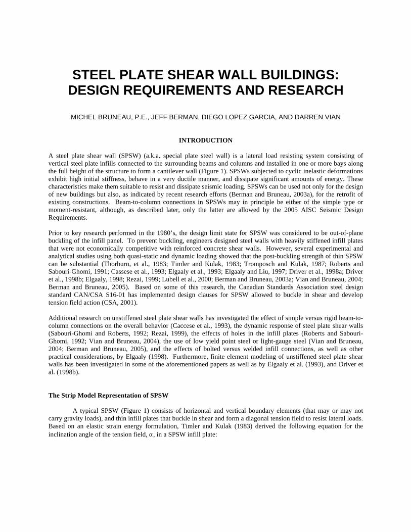
INTRODUCTION A steel plate shear wall (SPSW) (a.k.a. special plate steel wall) is a lateral load resisting system consisting of vertical steel plate infills connected to the surrounding beams and columns and installed in one or more bays along the full height of the structure to form a cantilever wall (Figure 1). SPSWs subjected to cyclic inelastic deformations exhibit high initial stiffness, behave in a very ductile manner, and dissipate significant amounts of energy. These characteristics make them suitable to resist and dissipate seismic loading. SPSWs can be used not only for the design of new buildings but also, as indicated by recent research efforts (Berman and Bruneau, 2003a), for the retrofit of existing constructions. Beam-to-column connections in SPSWs may in principle be either of the simple type or moment-resistant, although, as described later, only the latter are allowed by the 2005 AISC Seismic Design Requirements. Prior to key research performed in the 1980’s, the design limit state for SPSW was considered to be out-of-plane buckling of the infill panel. To prevent buckling, engineers designed steel walls with heavily stiffened infill plates that were not economically competitive with reinforced concrete shear walls. However, several experimental and analytical studies using both quasi-static and dynamic loading showed that the post-buckling strength of thin SPSW can be substantial (Thorburn, et al., 1983; Timler and Kulak, 1983; Tromposch and Kulak, 1987; Roberts and Sabouri-Ghomi, 1991; Cassese et al., 1993; Elgaaly et al., 1993; Elgaaly and Liu, 1997; Driver et al., 1998a; Driver et al., 1998b; Elgaaly, 1998; Rezai, 1999; Lubell et al., 2000; Berman and Bruneau, 2003a; Vian and Bruneau, 2004; Berman and Bruneau, 2005). Based on some of this research, the Canadian Standards Association steel design standard CAN/CSA S16-01 has implemented design clauses for SPSW allowed to buckle in shear and develop tension field action (CSA, 2001). Additional research on unstiffened steel plate shear walls has investigated the effect of simple versus rigid beam-to-column connections on the overall behavior (Caccese et al., 1993), the dynamic response of steel plate shear walls (Sabouri-Ghomi and Roberts, 1992; Rezai, 1999), the effects of holes in the infill plates (Roberts and Sabouri-Ghomi, 1992; Vian and Bruneau, 2004), the use of low yield point steel or light-gauge steel (Vian and Bruneau, 2004; Berman and Bruneau, 2005), and the effects of bolted versus welded infill connections, as well as other practical considerations, by Elgaaly (1998). Furthermore, finite element modeling of unstiffened steel plate shear walls has been investigated in some of the aforementioned papers as well as by Elgaaly et al. (1993), and Driver et al. (1998b). The Strip Model Representation of SPSW
A typical SPSW (Figure 1) consists of horizontal and vertical boundary elements (that may or may not carry gravity loads), and thin infill plates that buckle in shear and form a diagonal tension field to resist lateral loads. Based on an elastic strain energy formulation, Timler and Kulak (1983) derived the following equation for the inclination angle of the tension field, α, in a SPSW infill plate:
4 3
1
3601
1
21
tan
⋅⋅
+⋅⋅+
⋅⋅
+= −
LIh
Aht
ALt
cb
cα (1)
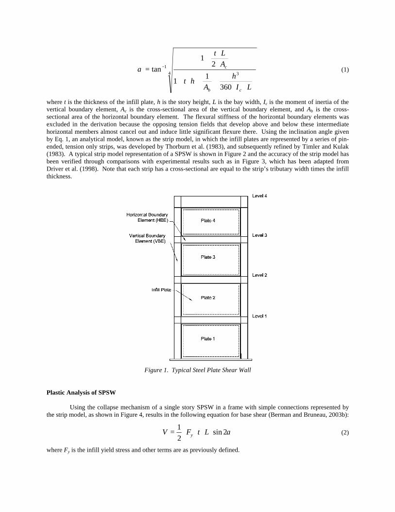
where t is the thickness of the infill plate, h is the story height, L is the bay width, Ic is the moment of inertia of the vertical boundary element, Ac is the cross-sectional area of the vertical boundary element, and Ab is the cross-sectional area of the horizontal boundary element. The flexural stiffness of the horizontal boundary elements was excluded in the derivation because the opposing tension fields that develop above and below these intermediate horizontal members almost cancel out and induce little significant flexure there. Using the inclination angle given by Eq. 1, an analytical model, known as the strip model, in which the infill plates are represented by a series of pin-ended, tension only strips, was developed by Thorburn et al. (1983), and subsequently refined by Timler and Kulak (1983). A typical strip model representation of a SPSW is shown in Figure 2 and the accuracy of the strip model has been verified through comparisons with experimental results such as in Figure 3, which has been adapted from Driver et al. (1998). Note that each strip has a cross-sectional are equal to the strip’s tributary width times the infill thickness.
Figure 1. Typical Steel Plate Shear Wall
Plastic Analysis of SPSW
Using the collapse mechanism of a single story SPSW in a frame with simple connections represented by the strip model, as shown in Figure 4, results in the following equation for base shear (Berman and Bruneau, 2003b):
α2sin21
⋅⋅⋅⋅= LtFV y (2)
where Fy is the infill yield stress and other terms are as previously defined.
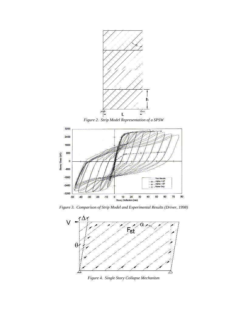
Figure 2. Strip Model Representation of a SPSW
Figure 3. Comparison of Strip Model and Experimental Results (Driver, 1998)
Figure 4. Single Story Collapse Mechanism
For a single-story SPSW in a frame with rigid beam-to-connections plastic analysis can again be used to find the base shear as:
h
MLtFV p
y
⋅+⋅⋅⋅⋅=
42sin
21
α (3)
where Mp is the smaller of the beam and column plastic moments. Equations are also derived for various collapse mechanisms in multistory SPSW in Berman and Bruneau (2003b). These equations can be used to determine an infill thickness for use in development of the strip model.
DESIGN OF STEEL PLATE SHEAR WALLS Ideally, a SPSW should be designed in such a way that all its steel panels dissipate energy through inelastic deformations when the structure is subjected to the expected seismic actions. Hence, for a given frame geometry (which is often dictated by architectural/functional considerations), the thickness of the steel panel at a given story should be determined as a function of the corresponding story shear demand. A practical approach consists of solving Eq. 2 for tw, which gives:
( )iy
iiw LF
Vt
α=
2sin2
(4)
where subindex “i” refers to the i-th story. Eq. 4 is slightly conservative for simple beam-to-column connections and somewhat conservative for moment-resistant connections, since the contribution of this type of connection to the lateral resistance of the SPSW is neglected in Eq. 2. It must be noted that Eq. 4 indicates that steel panels should have different thickness at different stories, a condition that is sometimes difficult to achieve in practice due to the availability of steel plates.
As mentioned before, the ultimate strength of a steel panel is fully developed only when the corresponding frame members are sufficiently stiff and strong to “anchor” the tension diagonals. Furthermore, for vertical boundary elements (VBEs), it has been recommended (Montgomery and Medhekar, 2001) that the moment of inertia Ic should be such that:
5.22
70.025.0
≤
c
w
ILt
h (5)
which leads to:
L
htI w
c
400307.0≥ (6)
While no practical expressions similar to Eq. 6 have been proposed for the horizontal boundary elements (HBEs) at the roof and foundation levels, sections providing the strength necessary to satisfy the corresponding flexural demands are likely to provide an adequate stiffness. It must be remembered that the HBEs at the roof and foundation levels must anchor the pulling action from a yielding steel panel, which generally results in substantial sizes.
It has been argued that, since the behavior of SPSWs is similar to that of vertical cantilever plate girders (VBEs act like “flanges”, HBEs act like “stiffeners” and steel panels act like the “web”), the former could be designed using well-established procedures suitable for the latter (Astaneh-Asl, 2001). However, while the plate girder analogy is conceptually valid and useful, it is quantitatively inadequate and leads to overly conservative designs. Detailed explanations, including quantitative comparisons, are presented in Berman and Bruneau (2004).
REGULATIONS AND CODE REQUIREMENTS The 2003 NEHRP Recommended Provisions for Seismic Regulations for New Buildings and Other Structures (Building Seismic Safety Council 2004) and the proposed 2005 Seismic Provisions for Structural Steel Buildings
(AISC, 2004) already include minimum design requirements for SPSWs (here, the 2003 NEHRP Provisions will be referred to as FEMA 450). It must be noted that SPSWs are denoted as Special Steel Plate Walls in FEMA 450 and as Special Plate Shear Walls in the 2005 AISC Provisions. In both documents, columns are designated as Vertical Boundary Elements (VBEs), beams are referred to as Horizontal Boundary Elements (HBEs), steel panels are denoted simply as webs, and a web and it’s surrounding HBEs and VBEs constitutes a panel. In these documents, the nominal strength of a web is set equal to: ( )α= 2sin42.0 cfwyn LtFV (7)
where Lcf is the clear distance between VBE flanges. In Eq. 7, α is to be calculated using Eq. 1. It must be noted that Eq. 7 is identical to Eq. 2 except that L (distance between VBE centerlines) is replaced by Lcf and the 0.50 factor is replaced by 0.42, which is simply 0.50 divided by an overstrength factor equal to 1.2. The design shear strength of a web is given by φ Vn, where φ = 0.90. According to these regulations, HBEs and VBEs are to remain essentially elastic under forces generated by fully yielded webs, but flexural hinges are allowed at the ends of HBEs. Both documents require that VBEs satisfy Eq. 6 and that 0.80 < L/h ≤ 2.50. Values of response modification factor R, system overstrength factor Ω0 and deflection amplification factor Cd are set equal to 7, 2 and 6, respectively. In addition, several details are specified for HBE-VBE connections. Finally, FEMA 450 imposes a limit on the slenderness of the web, quantitatively expressed by:
( )
yw FE
thL
25,min
≤ (8)
where E is the web’s Young modulus. The Canadian standard CAN/CSA S16-01 Limit States Design of Steel Structures (CSA, 2001) has included specifications for the design of SPSWs since 1994. In this document, the equivalent truss model (Thorburn et al. 1983) is recommended for preliminary design purposes. The idea consists of modeling the steel panels as diagonal steel truss members designed for the specified lateral loads and to meet drift requirements. The thickness of the steel panel at the i-th story, twi, is then given by:
i
iiiiw L
At
αθθ
=2sin
2sinsin22 (9)
where Ai and θi are the area and the angle of inclination (measured with respect to a vertical axis) of the equivalent truss member at the i-th story, respectively. While this approach is useful at the preliminary design stage, the resulting strength of the steel panels can be somewhat unconservative when the width-to-height ratio is not equal to unity (Berman and Bruneau 2003b). Another interesting feature of the CAN/CSA S16-01 standard consists of considering limited ductility plate walls (i.e., SPSWs with no special requirements for beam-to-column connections and assigned a force modification factor R = 2) in addition to ductile plate walls (i.e., SPSWs with moment-resisting beam-to-column connections and a force modification factor R = 5, the largest R value assigned to the most ductile systems in this standard). Other Design Issues for SPSW It is worthwhile to briefly mention some other design issues for SPSW which are likely appear in US design codes. Horizontal and vertical boundary elements should be designed to elastically resist development of the full expected tensile capacity of the infill plates. This ensures that the infill plate can yield in tension prior to plastic hinging of the boundary elements (providing for substantial energy dissipation in seismic applications). Such capacity design can be achieved by designing the boundary elements for the forces found from pushover analysis of the strip model, or indirectly from the procedure included in CAN/CSA S16-01. The connection of the infill plate to the boundary elements should also be designed for the expected tensile capacity of the infill plate and can use either a welded or bolted configuration. Four different connection details were developed, tested, and found to be equivalent by
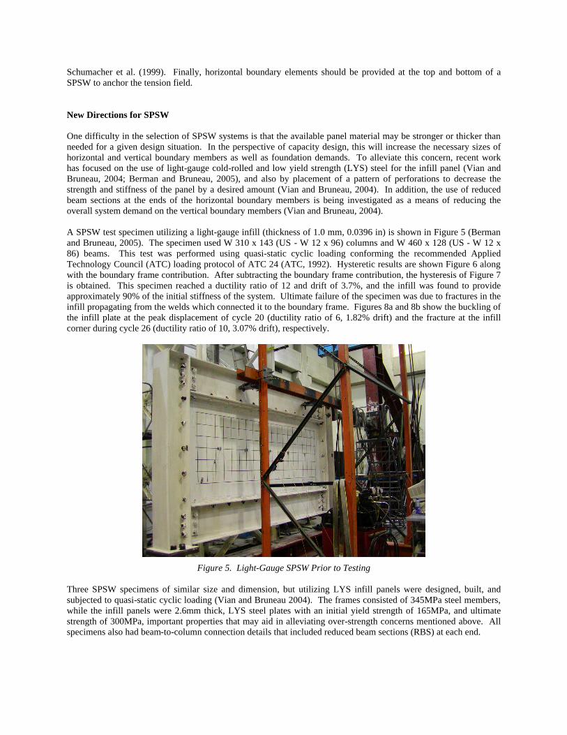
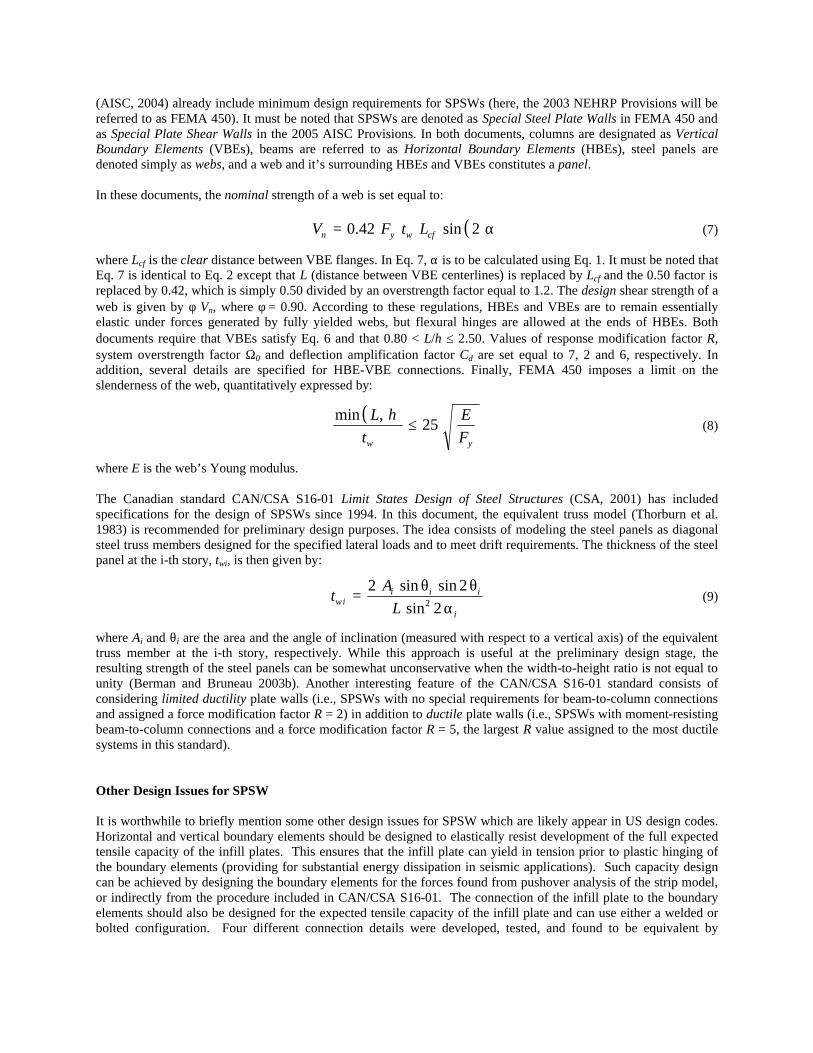
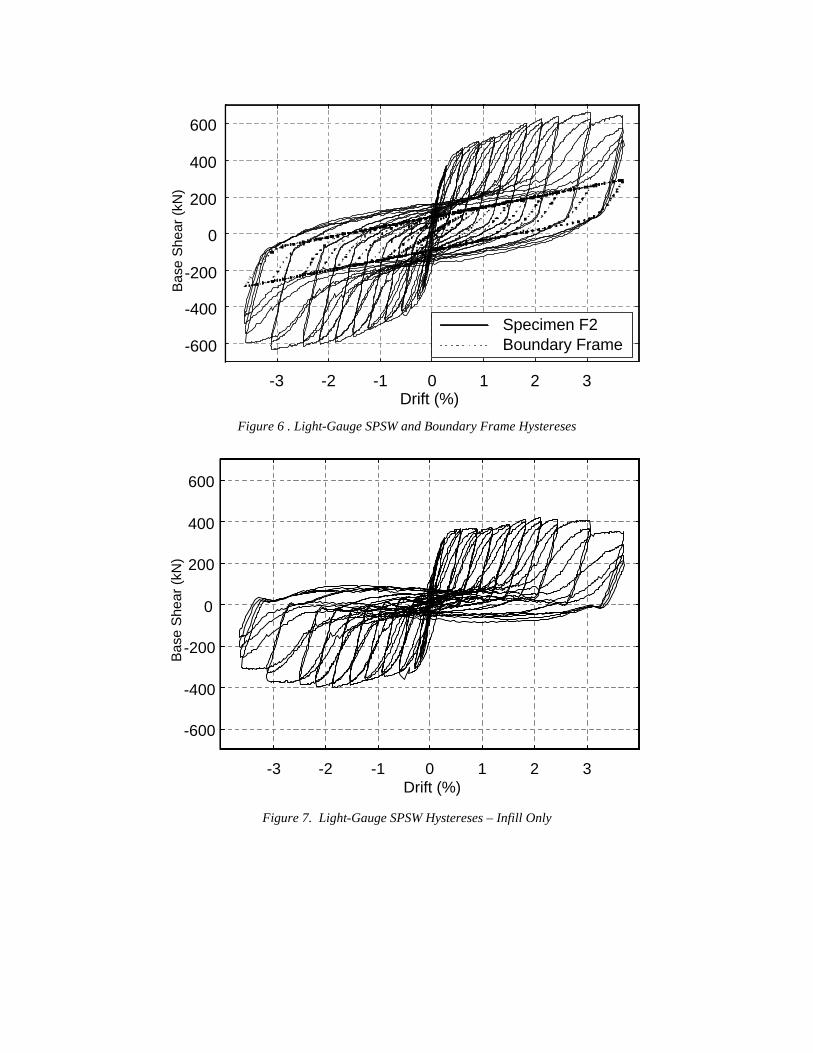
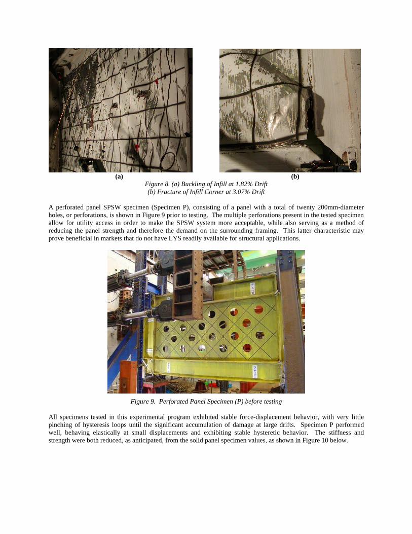
Schumacher et al. (1999). Finally, horizontal boundary elements should be provided at the top and bottom of a SPSW to anchor the tension field. New Directions for SPSW One difficulty in the selection of SPSW systems is that the available panel material may be stronger or thicker than needed for a given design situation. In the perspective of capacity design, this will increase the necessary sizes of horizontal and vertical boundary members as well as foundation demands. To alleviate this concern, recent work has focused on the use of light-gauge cold-rolled and low yield strength (LYS) steel for the infill panel (Vian and Bruneau, 2004; Berman and Bruneau, 2005), and also by placement of a pattern of perforations to decrease the strength and stiffness of the panel by a desired amount (Vian and Bruneau, 2004). In addition, the use of reduced beam sections at the ends of the horizontal boundary members is being investigated as a means of reducing the overall system demand on the vertical boundary members (Vian and Bruneau, 2004). A SPSW test specimen utilizing a light-gauge infill (thickness of 1.0 mm, 0.0396 in) is shown in Figure 5 (Berman and Bruneau, 2005). The specimen used W 310 x 143 (US - W 12 x 96) columns and W 460 x 128 (US - W 12 x 86) beams. This test was performed using quasi-static cyclic loading conforming the recommended Applied Technology Council (ATC) loading protocol of ATC 24 (ATC, 1992). Hysteretic results are shown Figure 6 along with the boundary frame contribution. After subtracting the boundary frame contribution, the hysteresis of Figure 7 is obtained. This specimen reached a ductility ratio of 12 and drift of 3.7%, and the infill was found to provide approximately 90% of the initial stiffness of the system. Ultimate failure of the specimen was due to fractures in the infill propagating from the welds which connected it to the boundary frame. Figures 8a and 8b show the buckling of the infill plate at the peak displacement of cycle 20 (ductility ratio of 6, 1.82% drift) and the fracture at the infill corner during cycle 26 (ductility ratio of 10, 3.07% drift), respectively.
Figure 5. Light-Gauge SPSW Prior to Testing
Three SPSW specimens of similar size and dimension, but utilizing LYS infill panels were designed, built, and subjected to quasi-static cyclic loading (Vian and Bruneau 2004). The frames consisted of 345MPa steel members, while the infill panels were 2.6mm thick, LYS steel plates with an initial yield strength of 165MPa, and ultimate strength of 300MPa, important properties that may aid in alleviating over-strength concerns mentioned above. All specimens also had beam-to-column connection details that included reduced beam sections (RBS) at each end.
-3 -2 -1 0 1 2 3Drift (%)
-600
-400
-200
0
200
400
600
Bas
e S
hear
(kN
)
Specimen F2Boundary Frame
Figure 6 . Light-Gauge SPSW and Boundary Frame Hystereses
-3 -2 -1 0 1 2 3Drift (%)
-600
-400
-200
0
200
400
600
Bas
e S
hear
(kN
)
Figure 7. Light-Gauge SPSW Hystereses – Infill Only
(a) (b)
Figure 8. (a) Buckling of Infill at 1.82% Drift (b) Fracture of Infill Corner at 3.07% Drift
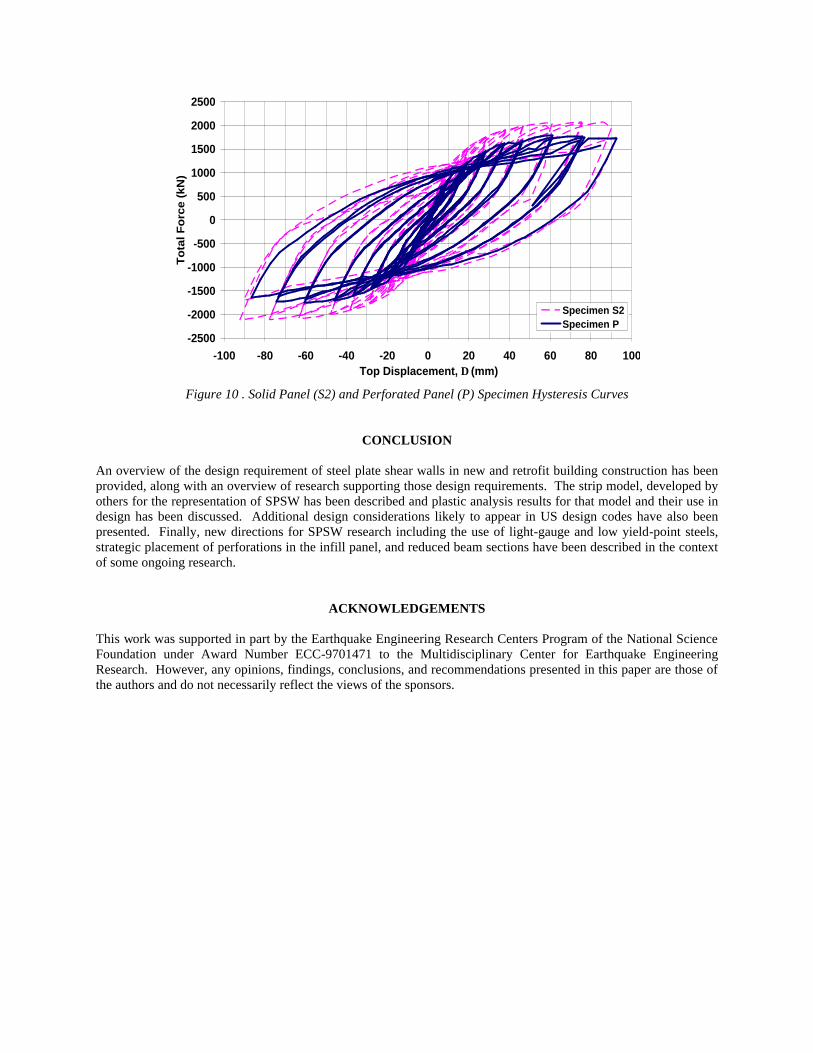
A perforated panel SPSW specimen (Specimen P), consisting of a panel with a total of twenty 200mm-diameter holes, or perforations, is shown in Figure 9 prior to testing. The multiple perforations present in the tested specimen allow for utility access in order to make the SPSW system more acceptable, while also serving as a method of reducing the panel strength and therefore the demand on the surrounding framing. This latter characteristic may prove beneficial in markets that do not have LYS readily available for structural applications.
Figure 9. Perforated Panel Specimen (P) before testing
All specimens tested in this experimental program exhibited stable force-displacement behavior, with very little pinching of hysteresis loops until the significant accumulation of damage at large drifts. Specimen P performed well, behaving elastically at small displacements and exhibiting stable hysteretic behavior. The stiffness and strength were both reduced, as anticipated, from the solid panel specimen values, as shown in Figure 10 below.
-2500
-2000
-1500
-1000
-500
0
500
1000
1500
2000
2500
-100 -80 -60 -40 -20 0 20 40 60 80 100Top Displacement, ∆ (mm)
To
tal F
orc
e (k
N)
Specimen S2Specimen P
Figure 10 . Solid Panel (S2) and Perforated Panel (P) Specimen Hysteresis Curves
CONCLUSION An overview of the design requirement of steel plate shear walls in new and retrofit building construction has been provided, along with an overview of research supporting those design requirements. The strip model, developed by others for the representation of SPSW has been described and plastic analysis results for that model and their use in design has been discussed. Additional design considerations likely to appear in US design codes have also been presented. Finally, new directions for SPSW research including the use of light-gauge and low yield-point steels, strategic placement of perforations in the infill panel, and reduced beam sections have been described in the context of some ongoing research.
ACKNOWLEDGEMENTS This work was supported in part by the Earthquake Engineering Research Centers Program of the National Science Foundation under Award Number ECC-9701471 to the Multidisciplinary Center for Earthquake Engineering Research. However, any opinions, findings, conclusions, and recommendations presented in this paper are those of the authors and do not necessarily reflect the views of the sponsors.
REFERENCES AISC (2004), “2005 Seismic Provisions for Structural Steel Buildings”, American Institute of Steel Construction,
Chicago, IL. Astaneh-Asl, A. (2001), ”Seismic Behavior and Design of Steel Shear Walls”, Steel Tip 37, Structural Steel
Educational Council, Moraga, CA. ATC (1992), Guidelines for Seismic Testing of Components of Steel Structures, Applied Technology Council,
Report 24. Berman, J. W., and Bruneau, M. (2003a), “Experimental Investigation of Light-Gauge Steel Plate Shear for the
Seismic Retrofit of Buildings”, Technical Report No. MCEER-03-0001, Multidisciplinary Center for Earthquake Engineering Research, Buffalo, NY.
Berman, J. W., and Bruneau, M. (2003b), “Plastic Analysis and Design of Steel Plate Shear Walls”, Journal of Structural Engineering, ASCE, Vol. 129, No. 11, pp 1448-1456.
Berman, J. W., and Bruneau, M. (2004) “Steel Plate Shear Walls are Not Plate Girders,” Engineering Journal, AISC, Vol.41, No.3, pp.95-106.
Berman, J.W., and Bruneau, M. (2005), “Experimental Investigation of Light-Gauge Steel Plate Shear Walls”, Journal of Structural Engineering, ASCE, in press, accepted 5/04, scheduled for 2/05.
Building Seismic Safety Council (2004), “2003 NEHRP Recommended Provisions for Seismic Regulations for New Buildings and Other Structures (FEMA 450)”, Federal Emergency Management Agency, Washington, DC.
Caccese, V., Elgaaly, M., and Chen, R., (1993), “Experimental Study of Thin Steel-Plate Shear Walls Under Cyclic Load”, Journal of Structural Engineering, ASCE, Vol. 119, No. 2, Feb. 1993, pp. 573-587.
CSA, (2001), Limit States Design of Steel Structures, CAN/CSA S16-01, Canadian Standards Association, Willowdale, Ontario, Canada.
Driver, R.G., Kulak, G.L., Kennedy, D.J.L., and Elwi, A.E. (1998a), “Cyclic Test of Four-Story Steel Plate Shear Wall”, Journal of Structural Engineering, ASCE, Vol. 124, No. 2, Feb. 1998, pp 112-130.
Driver, R.G., Kulak, G.L., Elwi, A.E. and Kennedy, D.J.L. (1998b), “FE and Simplified Models of Steel Plate Shear Wall”, Journal of Structural Engineering, ASCE, Vol. 124, No. 2, Feb. 1998, pp. 121-130.
Elgaaly, M. (1998), “Thin Steel Plate Shear Walls Behavior and Analysis”, Thin Walled Structures, Vol. 32, pp. 151-180.
Elgaaly, M., Caccese, V., and Du, C. (1993), “Postbuckling Behavior of Steel-Plate Shear Walls Under Cyclic Loads”, Journal of Structural Engineering, ASCE, Vol. 119, No. 2, Feb. 1993, pp. 588-605.
Elgaaly, M., and Lui, Y. (1997), “Analysis of Thin-Steel-Plate Shear Walls”, Journal of Structural Engineering, ASCE, Vol. 123, No. 11, Nov. 1997, pp 1487-1496.
Lubell, A.S., Prion, H.G.L., Ventura, C.E., and Rezai, M. (2000), “Unstiffened Steel Plate Shear Wall Performance Under Cyclic Loading”, Journal of Structural Engineering, ASCE, Vol. 126, No.4, pp. 453-460.
Montgomery, C.J., and Medhekar, M. (2001), “Discussion on “Unstiffened Steel Plate Shear Wall Performance under Cyclic Loading”, Journal of Structural Engineering, ASCE, Vol. 127, No. 8, pp. 973-973.
Rezai, M. (1999), “Seismic Behavior of Steel Plate Shear Walls by Shake Table Testing”, Ph.D. Dissertation, University of British Columbia, Vancouver, British Columbia, Canada.
Roberts, T.M., and Sabouri-Ghomi, S. (1991), “Hysteretic Characteristics of Unstiffened Plate Shear Panels”, Thin-Walled Structures, Vol. 12, No. 2, pp145-162.
Roberts, T.M., and Sabouri-Ghomi, S. (1992), “Hysteretic Characteristics of Unstiffened Perforated Steel Plate Shear Panels”, Thin-Walled Structures, Vol. 14, No. 2, pp 139-151.
Schumacher, A., Grondin, G.Y., and Kulak, G.L., “Connection of Infill Panels in Steel Plate Shear Walls”, Canadian Journal of Civil Engineering, Vol. 26, No. 5, pp. 549-563.
Thorburn, L.J., Kulak, G.L., and Montgomery, C.J. (1983), "Analysis of Steel Plate Shear Walls", Structural Engineering Report No. 107, Department of Civil Engineering, University of Alberta, Edmonton, Alberta, Canada.
Timler, P.A. and Kulak, G.L. (1983), "Experimental Study of Steel Plate Shear Walls", Structural Engineering Report No. 114, Department of Civil Engineering, University of Alberta, Edmonton, Alberta, Canada.
Tromposch, E.W., and Kulak, G.L. (1987), “Cyclic and Static Behaviour of Thin Panel Steel Plate Shear Walls”, Structural Engineering Report No. 145, Department of Civil Engineering, University of Alberta, Edmonton, Alberta, Canada.
Vian, D., and Bruneau, M. (2004), “Testing of Special LYS Steel Plate Shear Walls”, Proceedings of the 13th World Conference on Earthquake Engineering, Paper No. 978, Vancouver, British Columbia, Canada, August 1-6, 2004.