Embed Size (px)
Citation preview

CRUSHWORTHINESS OF POLYMERIC FOAM USED AS CORE
COMPOSITE SANDWICH STRUCTURE
HAFIZAWATI BINTI ZAKARIA
A dissertation submitted in partial fulfillment of the
requirements for the award of the degree of
Master of Engineering (Mechanical-Pure)
Faculty of Mechanical Engineering
Universiti Teknologi Malaysia
MAY 2006

To my beloved family,
The believe in you brings my dreams comes true.
To my hubby, Fakhrin Hakimi Mustofa and sons, Amir Hakim and Luqman Hakim who
have brought me love, patience
and understanding into our lives.

ACKNOWLEDGEMENT
“In the name of Allah that the most Gracious, the most Merciful”
Foremost, my greatest gratitude goes to ALLAH SWT for giving me the energy,
strength and spirit to make it possible to complete this thesis.
In particular, I wish to express my deepest appreciation to my supervisor, Dr.
Amran Alias for encouragement, guidance and valuable critics throughtout the project. I
am also very thankful to Mr. Halim Irwan Ibrahim for his guidance and advices. Also
many thanks to Mr. Sharul for preparing the manufacturing tools and materials, and to
Mr. Rizal for his assistance in settig up the Instron test machine. Without their continued
support and interest, this thesis would not have been the same as presented here.
Finally, I owed an immense debt of gratitude to my families for their love and
support to me. To someone who always stays beside me in worse and better time,
thanks for your advice, guidance and support.
THANK YOU
ABSTRACT
PUR foam has been used extensively as core of sandwich structures in the aerospace and
automobile industries. The understanding of their behaviour under crush conditions is
extremely important for the design and manufacturing of these engineering structures
since crush problems are directly related to structural integrity and safety requirements.
In this paper, selected foam cored polymer sandwich beam were subjected to static three
point bend tests. The beams were loaded beyond first failure to study the nonlinear post
failure behaviour. Provided the beam fails in shear of core and skin delamination. The
post failure response is dominated by the crushing of the core and upper skin
compression. A theoretical model by Mines and Jones is used to simulate the post failure
response of the beams. The model assumes an idealized plastic hinge in the central
loading point and relates the beam constituent material properties to the beam overall
response. The beams were also subjected with impact test. The impact response of foam
based sandwich structures has been investigated using a build-up falling weight impact
method and load cell system.

ABSTRAK
Penggunaan ‘PUR foam’ sebagai teras kepada struktur ‘sandwich’ di dalam industri
automobil dan aero-angkasa semakin meluas. Oleh itu, pemahaman tentang gayalaku
mekanikal di bawah keadaan hentaman adalah sangat penting untuk tujuan rekabentuk
dan pembuatan struktur kejuruteraan kerana masalah hentaman berkait secara langsung
dengan kekuatan struktur dan keperluan keselamatan. Untuk kertas kerja ini, rasuk
‘foam’ polimer ‘sandwich’ yang telah dipilih dibebankan dengan beban lenturan dalam
ujian lenturan sistem pembebanan tiga-titik secara statik. Struktur rasuk itu dikenakan
beban sehingga melangkaui kegagalan struktur rasuk yang pertama untuk membolehkan
gayalaku selepas kegagalan pertama dikaji. Didapati kegagalan rasuk ialah berlakunya
ricihan pada teras rasuk dan ‘skin delamination’. Tindak balas selepas kegagalan yang
pertama ialah rasuk mengalami kerenyukan pada teras dan mampatan pada kulit di
bahagian atas rasuk. Teori yang diterbitkan oleh Mines dan Jones digunakan untuk
simulasi tindakbalas rasuk selepas kegagalan berlaku. Model ini menganggapkan
bahawa berlakunya keplastikan penuh secara ideal di tengah-tengah titik tindakan beban
dan tindak balas yang berlaku berkait rapat dengan sifat-sifat bahan rasuk itu. Selain itu,
sistem rasuk ini juga dibebankan dengan dengan ujian bebanan hentakan. Tindak balas
terhadap hentakan oleh foam based struktur sandwich disiasat dengan keadah hentakan
pemberat dan sistem ‘load cell’.

TABLE OF CONTENT
CHAPTER TITLE PAGE
TITLE PAGE i
DECLARATION ii
DEDICATION iii
ACKNOWLEDGEMENT iv
ABSTRACT v
ABSTRAK vi
TABLE OF CONTENTS vii
LIST OF TABLES xi
LIST OF FIGURES xii
NOMENCLATURES xvi
LIST OF APPENDICES xviii
1 INTRODUCTION
1.1 Background of Project 2
1.2 Problem Statement 3
1.3 Objective 4
1.4 Scope of Study 4
1.5 Methodology 5
2 THEORY
2.1 Laminate Analysis 7
2.1.1 Modulus and Stiffness of Skin 7
2.1.2 Flexural Rigidity and Beam Stiffness 9
2.1.3 Failure Stress and Deflection 10
2.2 Limit Analysis 12
2.2.1 Determining the Neutral Axis of Beam 12
2.2.2 Elastic-Plastic Bending Moment 14
2.2.3 Hinge Analysis 15
2.2.4 Tensile Strain in Lower Skin 17
2.2.5 Multiaxial Stress Criterion 18
2.2.6 Energy Absorption 20
3 MATERIAL DESCRIPTION
3.1 Glass Fiber Reinforce Plastic 21
3.1.1 Glass Fibre 22
3.1.2 Various Form of Glass Fibre 24
3.1.2.1 Roving 24
3.1.2.2 Chopped Strands 25
3.1.2.3 Woven Roving 25
3.1.2.4 Woven Cloth 26
3.1.2.5 Chopped Strand Mat (CSM) 27
3.1.2.6 Surface Tissue 27
3.1.3 Properties of Glass Fibre 28
3.1.3.1 Mechanical Strength 28
3.1.3.2 Environmental and Corrosion Resistance 29
3.1.3.3 Heat and Fire Resistance 29
3.1.3.4 Density 29
3.1.4 Other Characteristics 30
3.2 Epoxy Resin 32
3.3 Polyurethane Foam 33
3.3.1 The Chemistry of Polyurethane Foams 34
3.3.2 Basic Components of PU Foam 35
3.3.2.1 Polyurethane 36
3.3.2.2 Polyol 36
3.3.2.3 Catalyst 37
3.3.2.4 Surfactants 38
3.3.2.5 Blowing Agents 40
4 BEAM MANUFACTURE
4.1 Method of Fabricating PUR Foam 42
4.2 Procedure of Fabricating Foam 44
4.3 Density Evaluation 46
4.4 Hand Lay-Up Method 48
5 EXPERIMENTAL SETUP AND THEORETICAL ANALYSIS
5.1 Test on Foam Core 51
5.1.1 Uniaxial Compression Test 51
5.1.2 Uniaxial Tension Test 53
5.1.3 Shear Test 57
5.1.4 Biaxial Test 61
5.1.4.1 Test and Behavior in Biaxial Test 62
5.2 Test on Composite Skin 65

5.2.1 Tensile Test for Skin GPRC 65
5.3 Test on Sandwich Structure 66
5.3.1 Three Point Bending Test 66
5.3.2 Impact Test 69
6 RESULT AND DISCUSSION
6.1 PUR Foam 72
6.1.1 Uniaxial Compression Result 72
6.1.2 Uniaxial Tension Result 77
6.1.3 Shear Test 81
6.1.4 Biaxial Test 85
6.2 Composite Skin 95
6.2.1 Tensile Test of Composite Skin 95
6.2.2 The Flexural Test of Composite Skin 96
6.3 Sandwich Structure 97
6.3.1 Three Point Bending Test 97
6.3.2 Impact Test 108
7 CONCLUSION AND RECOMMENDATION
7.1 Conclusion 112
7.2 Recommendation 113
REFERENCES 114
APPENDICES 116
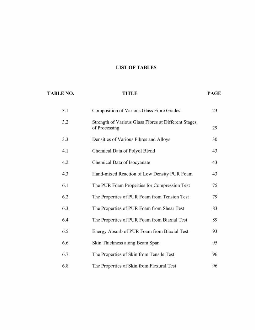
LIST OF TABLES
TABLE NO. TITLE PAGE
3.1 Composition of Various Glass Fibre Grades. 23 3.2 Strength of Various Glass Fibres at Different Stages of Processing 29 3.3 Densities of Various Fibres and Alloys 30 4.1 Chemical Data of Polyol Blend 43 4.2 Chemical Data of Isocyanate 43 4.3 Hand-mixed Reaction of Low Density PUR Foam 43 6.1 The PUR Foam Properties for Compression Test 75 6.2 The Properties of PUR Foam from Tension Test 79 6.3 The Properties of PUR Foam from Shear Test 83 6.4 The Properties of PUR Foam from Biaxial Test 89 6.5 Energy Absorb of PUR Foam from Biaxial Test 93 6.6 Skin Thickness along Beam Span 95 6.7 The Properties of Skin from Tensile Test 96 6.8 The Properties of Skin from Flexural Test 96

LIST OF FIGURES
FIGURE NO. TITLE PAGE
1.1 Force-Deflection Schematic for Sandwich Beam (A-Upper skin compression, B-Core crushing, C-Lower skin tensile failure) 3 1.2 A Flow Chart for Experimental Work 5 2.1 Elastic-Plastic Model for Loading Point Hinge. 12 2.2 The Plastic Hinge (ABCD) Model in the Vicinity of Central Loading 15 3.1 Flow Diagram for the Manufacture of Glass Fibre. 23 3.2 Roving 24 3.3 Chopped Strands 25 3.4 Woven Roving 26 3.5 Woven Cloth 26 3.6 Chopped Strand Mat 27 3.7 Surface Tissue 28 3.8 Effect of Water and Surface Active Agents on the Strength of Glass Fibres 31 3.9 Urethane Reaction 34 3.10 Isocyanate Reaction to Produce Substitute Urea 35 3.11 Reaction of Carbamic Acid with Isocyanate 35

3.12 Tolylene Diisocyanate (TDI) 36 3.13 4,4’-Diphenylmethane Diisocyanate (MDI) 36 3.14 Structures of PMDS-Polyether Graft Copolymer Surfactants 39 4.1 The Mixing Machine 44 4.2 Bubble Nucleation and Growth 45 4.3 The PUR Foam Specimen in Cube Dimension 45 4.4 The PUR Foam Specimen in Beam Dimension 46 4.5 Sketching Variety of Cells 47 4.6 The Hand Lay-up Method of Skin Fabrication 48 5.1 Compression Test 51 5.2 Free Body Diagram of Compression Test 51 5.3 The Compression Test Set-up 52 5.4 Tensile test 54 5.5 Free Body Diagram of Tensile Test 54 5.6 Tensile Test Rig 55 5.7 The Tensile Test Set-up 55 5.8 Shear Test 57 5.9 Free Body Diagram of the Shear Test 58 5.10 The Shear Test Rig 58 5.11 The Shear Test Set-up 59 5.12 The PUR Foam Specimens glued on the Steel Plate 1 61 5.13 The Specimen completely glued to the Steel Plate 2 61 5.14 The Biaxial Specimen 62

5.15 Layout of the Compressive Shear Test Rig 62 5.16 The Multi Axial Test Rig 63 5.17 The Specimen Schematic for Tensile Test 65 5.18 The Specimen for Tensile Test of Skin Material 65 5.19 The Instron Machine Setup for Three-Point Bending Test 66 5.20 The Specimen Setup for Three-Point Bending Test 67 5.21 Experimental Setup for the Three-Point Bending Test 68 5.22 Three-Point Bending Configuration 68 5.23 The Apparatus used in Impact Test 69 5.24 The DEWETRON Software used in Impact Test 70 5.25 The Specimen Setup for Impact Test 71 6.1 Typical Compression of Stress-Strain Curve 73 6.2 Comparison Test for Various Strain Rates 74 6.3 The Effect of Strain Rates on the Properties of PUR Foam in Compression Tests 76 6.4 Typical Tensile Stress-Strain Curve 78 6.5 The Tensile Tests for Various Strain Rates 78 6.6 The Effect of Strain Rates on the Properties of PUR Foam in Tensile Tests 80 6.7 Typical Shear Stress-Strain Curve 82 6.8 Shear Tests with Various Strain Rates 82 6.9 The Effect of Strain Rate on the Properties of PUR Foam in Shear Test 84 6.10 Typical Biaxial Stress-Strain Curve 86 6.11 Typical Biaxial Crush Behavior for various Strain Rates 88

6.12 The Slopes of Biaxial Test for various Strain Rates 89 6.13 The Effect of Strain Rate on the Properties of PUR Foam in Biaxial Test 91 6.14 The Effect of Strain Rate on the Biaxial Yield Stress of PUR Foam 91 6.15 Typical Work in Biaxial Test represented by the area under Stress-Strain Curve 92 6.16 Energy Absorption of PUR Foam in various Strain Rates under Biaxial Tests 93 6.17 Three-Point Bending Test for various Strain Rates 98 6.18 Simplification Model for Three-Point Bending Test 99 6.19 Simpson’s Rule Configuration for the Three-Point Bending Test 100 6.20 Position of Neutral Axis, z for the Sandwich Beam 103 6.21 Comparison between Model and Experimental Force-Deflection value for Sandwich Beam: CHS5 104 6.22 Comparison between Model and Experimental Force-Deflection value for Sandwich Beam: CHS10 104 6.23 Comparison between Model and Experimental Force-Deflection value for Sandwich Beam: CHS20 105 6.24 Comparison of Energy Absorbed by PUR Foam-based Sandwich Beams 106 6.25 Observation of Specimens after Static Three-point Bending Tests for various Strain Rates 107 6.26 Calibration Graph for Dewetron Software for Impact Test 108 6.27 Force Histories at three Impact Velocities 109 6.28 Observation of Specimens after Impact Tests for various Drop Weight Velocities 110

NOMENCLATURES
B Beam width (mm)
c Core thickness (mm)
d Distance between centroidal axis of skins (mm)
h Total beam thickness (mm)
t Skin thickness (mm)
L Beam span (mm)
E Modulus of elasticity (GPa)
v Volume fraction
[Q11]k Stiffness of kth lamina
ν Poisson’s ratio
D Flexural rigidity (Nm)
k Beam stiffness (N/m)
Fs Static failure load (N)
[σ]k Faulire stress in kth lamina (MPa)
τ Shear stress (MPa)
α Axial force component (N)
β Moment component (Nm/m)
M Moment of a section (Nm)
F Load or force (N)
εf Initial strain for core crushing
εm Upper core surface strain
z Distance from upper core surface to neutral axis (mm)
g Work hardening index of core (MPa)
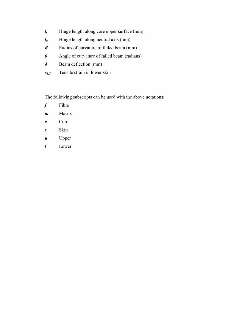
lt Hinge length along core upper surface (mm)
lo Hinge length along neutral axis (mm)
R Radius of curvature of failed beam (mm)
θ Angle of curvature of failed beam (radians)
δ Beam deflection (mm)
ε1,2 Tensile strain in lower skin
The following subscripts can be used with the above notations;
f Fibre
m Matrix
c Core
s Skin
u Upper
l Lower
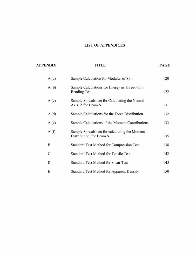
LIST OF APPENDICES
APPENDIX TITLE PAGE
A (a) Sample Calculation for Modulus of Skin 120 A (b) Sample Calculations for Energy in Three-Point Bending Test 122 A (c) Sample Spreadsheet for Calculating the Neutral Axis, Z for Beam S1 131 A (d) Sample Calculations for the Force Distribution 132 A (e) Sample Calculations of the Moment Contributions 133 A (f) Sample Spreadsheet for calculating the Moment Distribution, for Beam S1 135 B Standard Test Method for Compression Test 138 C Standard Test Method for Tensile Test 142 D Standard Test Method for Shear Test 145 E Standard Test Method for Apparent Density 150
CHAPTER 1
INTRODUCTION
The evolvement of material in usage applications has never stopped. Nowadays,
the development of structure with the use of polymeric composite material is in rapid
progress. One of the important aspects in these structural designs is that the capability of
the polymeric composite materials to withstand impact load. Structures are designed in
consideration of absorbing energy under impact conditions.
Another aspect needs to be looked into is the replacement of metal, concrete and
wood structures with polymer composite materials. Man has moved from using pure
materials such as metal to alloy and consequently polymer composite with certain
purposes. The main purposes are to achieve weight savings, take advantage of new
materials processing methods and improve the properties of the material for certain
applications.
Furthermore, in the case of impact response, a complex three dimensional
structural behavior of the material occurs. In order to design complex geometry of the
structures for impact resistance, it is a need to study a simple structure element of the
polymer composite material.
A simple polymer composite structure commonly used today is sandwich
structure. The sandwich construction is made up of a lightweight core material
sandwiched between high strength and high modulus skins. In most sandwich
constructions, core materials include balsa wood, aluminum, paper and plastic
honeycombs, cellular foams and CorematR. The skins are usually resin impregnated
glass, aramid or carbon fibres. The matrix resin can be of polyester, vinyl ester, phenolic
thermosets and other more recent high performance thermoplastics. In this study, the
work is concerned on the sandwich beams with polyester resin impregnated glass fibers
for skins and rigid polyurethane foam as the core material. Due to high stiffness and
strength to weight ratio of composites and thin walled sectional geometry of FRP
shapes, impact is the most likely mode of failure before material failure.
1.1 Background of Project
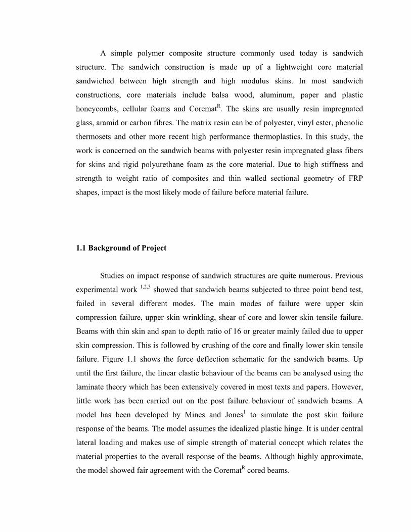
Studies on impact response of sandwich structures are quite numerous. Previous
experimental work 1,2,3 showed that sandwich beams subjected to three point bend test,
failed in several different modes. The main modes of failure were upper skin
compression failure, upper skin wrinkling, shear of core and lower skin tensile failure.
Beams with thin skin and span to depth ratio of 16 or greater mainly failed due to upper
skin compression. This is followed by crushing of the core and finally lower skin tensile
failure. Figure 1.1 shows the force deflection schematic for the sandwich beams. Up
until the first failure, the linear elastic behaviour of the beams can be analysed using the
laminate theory which has been extensively covered in most texts and papers. However,
little work has been carried out on the post failure behaviour of sandwich beams. A
model has been developed by Mines and Jones1 to simulate the post skin failure
response of the beams. The model assumes the idealized plastic hinge. It is under central
lateral loading and makes use of simple strength of material concept which relates the
material properties to the overall response of the beams. Although highly approximate,
the model showed fair agreement with the CorematR cored beams.
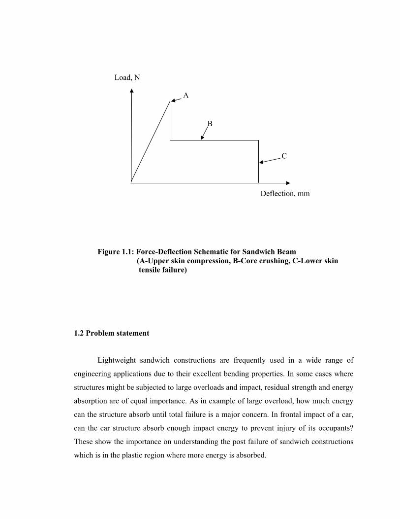
Figure 1.1: Force-Deflection Schematic for Sandwich Beam (A-Upper skin compression, B-Core crushing, C-Lower skin
tensile failure)
1.2 Problem statement
Lightweight sandwich constructions are frequently used in a wide range of
engineering applications due to their excellent bending properties. In some cases where
structures might be subjected to large overloads and impact, residual strength and energy
absorption are of equal importance. As in example of large overload, how much energy
can the structure absorb until total failure is a major concern. In frontal impact of a car,
can the car structure absorb enough impact energy to prevent injury of its occupants?
These show the importance on understanding the post failure of sandwich constructions
which is in the plastic region where more energy is absorbed.
Load, N
Deflection, mm
A
B
C

1.3 Objective
The objectives of this study are:
a) to determine the energy absorbed by the foam from the biaxial test
b) to determine the energy absorbed by the foam as core of composite sandwich
structure from the three-points bending test.
c) to investigate the type of the post failure behaviour of this polymeric
sandwich structure
d) to investigate the validity of the model with the beam tests.
1.4 Scope of Study
The scopes of this project are as stated below:
1. Study the present technique in producing the polymeric foam: rigid polyurethane
foam, as core sandwich structure.
2. Fabricate the foam core using mixing machine.
3. Study the characteristics of PUR Foam by performing mechanical tests as below:
i. Uniaxial Tension Test
ii. Uniaxial Compression Test
iii. Pure Shear Test
iv. Biaxial Test
4. Study the characteristics of glass fibers and polyester resin and to perform tensile
tests on the skin of sandwich structure.
5. Study the theory that relates with three-point bending and impact analysis.
6. Perform mechanical tests of the sandwich structure:
i. Three Point Bending Test
ii. Dynamic Impact
7. Analyze the experiment data.
8. Carry out the theoretical analysis.
9. Comparison and discussion of data analysis.
10. Conclusion and suggestion/recommendation for future study.
11. Report writing.
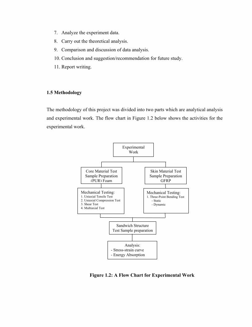
1.5 Methodology
The methodology of this project was divided into two parts which are analytical analysis
and experimental work. The flow chart in Figure 1.2 below shows the activities for the
experimental work.
Figure 1.2: A Flow Chart for Experimental Work
Experimental Work
Core Material Test Sample Preparation
(PUR) Foam
Skin Material Test Sample Preparation
GFRP
Mechanical Testing: 1. Uniaxial Tensile Test 2. Uniaxial Compression Test 3. Shear Test 4. Multiaxial Test
Mechanical Testing: 1. Three-Point Bending Test - Static - Dynamic
Sandwich Structure Test Sample preparation
Analysis: - Stress-strain curve - Energy Absorption

The core specimens were prepared by mixing the polyol blend and isocyanate of
1:1 ratio respectively. The determination of the tensile, compression, and shear
properties of the PU foam were carried out according to the ASTM C297, ASTM
D1621-2000 and ASTM C365-2000, and ASTM C273 standards respectively.
The properties of this material used to analyze the failure characteristic of the
core sandwich structure. The face sheets were prepared by filament winding
process. The determination of the failure characteristic of the GFRP was carried
out by the quasi-static and dynamic test and axial test. The sandwich structures
were prepared by using in-situ technique. Thus, from the stress-strain curve
obtained the energy absorption is analyzed. Apart from that the energy
absorption is also being analyzed theoretically.