Embed Size (px)
Citation preview

Palleti, H.N.K.T., Zhang, S., Dulieu-Barton, J.M., Fruehmann, R.K. and Thomsen, O.T., “Influence of thermomechanical interaction effects on the failure behaviour of polymer foam cored sandwich panels”, Journal of Sandwich Structures and Materials, 17, 2015, 308-331. DOI: 10.1177/1099636214567602.
1
Influence of thermomechanical interaction effects on the failure
behaviour of polymer foam cored sandwich panels
H N K T Palleti1, S Zhang2, R K Fruehmann3, J M Dulieu-Barton1,3*, O T Thomsen1,3,
1 Department of Mechanical and Manufacturing Engineering, Aalborg University, Aalborg DK-9220,
Denmark
2 Science and Technology on Integrated Logistics Support Laboratory, National University of Defense
Technology, China
3 Faculty of Engineering and the Environment, University of Southampton, Southampton, SO17 1BJ,
UK
* Corresponding author e-mail: [email protected]
Abstract
The paper presents an experimentally based and numerically supported investigation of the
collapse behaviour of polymer foam cored sandwich beams subjected to combined
mechanical and thermal loading. Recent analytical and numerical modelling results available
in the literature have ascertained that collapse may be due to loss of stability induced by
nonlinear interactions between mechanical loads and thermally induced deformations, when
accounting for the reduction of the polymer foam core mechanical properties with increasing
temperature. In the paper, experiments are devised whereby a thermal gradient is introduced
into a sandwich beam specimen loaded in three point bending. The experiments cover a range
of temperatures where one face sheet is heated from room temperature (25°C) to just below
the glass transition temperature of the polymer foam core (70°C) and the other face sheet
remains at room temperature. Digital image correlation (DIC) is used to obtain the local
displacement field of the sandwich beam and its temperature is monitored using an infrared
detector and thermocouples. The experimental results are compared with the predictions of
both a generally nonlinear finite element model and an analytical so-called high-order
sandwich panel theory (HSAPT) model. It is important to note that the HSAPT model has
clear limitations as it takes into account only the geometric nonlinearity and thermal
degradation of the foam core elastic properties, and it further assumes that the sandwich
constituents are linear elastic with infinite straining capability. The HSAPT model predicts
the occurrence of a strongly nonlinear load response leading to loss of stability (limit point

Palleti, H.N.K.T., Zhang, S., Dulieu-Barton, J.M., Fruehmann, R.K. and Thomsen, O.T., “Influence of thermomechanical interaction effects on the failure behaviour of polymer foam cored sandwich panels”, Journal of Sandwich Structures and Materials, 17, 2015, 308-331. DOI: 10.1177/1099636214567602.
2
behaviour). However, the experiments show that for the investigated sandwich beam
configuration it is necessary to include the nonlinear material properties in the modelling, as
the nonlinear beam response leading to failure and collapse is significantly influenced by
plastic deformations in the constituent materials. Thus, core indentation and extensive
plasticity precedes the transition to loss of stability driven by geometric nonlinearity and
thermomechanical interaction effects. Finite element analyses that include both geometric
and material nonlinearities provide results that correlate closely with the experimental
observations. The work presented lays the foundations of a methodology for validating
complex thermomechanical behaviour in sandwich structures using non-contact full-field
measurement systems, and it demonstrates that analytical or numerical models based on the
assumption of linear elastic material behaviour (such as the HSAPT model referenced in the
paper) generally cannot adequately describe the thermomechanical behaviour of foam cored
sandwich structures.
1 Introduction
Sandwich structures are typically exposed to mechanical loading as well as to aggressive
environmental conditions that may include elevated temperatures. Traditionally, a typical
design process of such structures examines the responses due to the mechanical loads and the
thermal loading, i.e. the deformations induced by thermal sources, separately. However, the
interaction between the mechanical and thermal loads may lead to an unsafe response with
loss of stability and structural integrity, particularly when the deformations are large and the
mechanical properties (e.g. stiffness and strength) reduce as the temperature is raised.
Significant degradation of the mechanical properties of polymer foam core materials may
occur well within the operation temperature range. It should be noted that in the present
context the term “degradation” is used as a short form of “degradation or reduction of
mechanical properties”. In general, this thermal degradation of polymer foam cored
sandwich structures is not thoroughly understood by researchers and industry.
There is a growing concern within the wind turbine blade, marine and aeronautical sectors
about the simultaneous action of mechanical loads and elevated temperatures on polymer
foam cored sandwich structures, which may compromise the structural integrity. The
manufacturers of polymer foam materials, including PVC, PET, PMI and other types, offer
limited and incomplete information about the temperature dependency of the core mechanical
Palleti, H.N.K.T., Zhang, S., Dulieu-Barton, J.M., Fruehmann, R.K. and Thomsen, O.T., “Influence of thermomechanical interaction effects on the failure behaviour of polymer foam cored sandwich panels”, Journal of Sandwich Structures and Materials, 17, 2015, 308-331. DOI: 10.1177/1099636214567602.
3
properties. Furthermore they do not provide any significant design guidelines about the
combined influence of mechanical and thermal loads.
Recently, due to the growing concern regarding the behaviour of polymer foam cored
sandwich structures when exposed to combined thermal and mechanical loading scenarios,
several researchers have considered the thermomechanical response of sandwich structures.
A significant amount of the research has involved the use of high-order theories to model the
thermomechanical response of laminated or sandwich panels including Najafizadeh and
Heydari [1], Dafedar and Desai [2], Kapuria and Achary [3], Shiau and Kuo [4], Matsunaga
[5], Dawe [6] and Cooke [7]. However, none of these have included the core through-
thickness flexibility.
A more comprehensive approach is offered by the so-called high-order sandwich panel theory
(HSAPT), which models the layered sandwich panel as two face sheets and a core material
that are interconnected through the equilibrium and compatibility conditions. Moreover, the
HSAPT formulation incorporates the through-thickness flexibility of the core, but assumes
that the core in-plane stiffness is negligible. The HSAPT approach has been used in several
studies that investigate the influence of hygrothermal effects, buckling (global and local) and
nonlinear response, see Frostig [8]; Frostig and Baruch [9]; Sokolinsky and Frostig [10],
Frostig and Thomsen [11, 12] and Frostig et al [13]. Most importantly in the context of the
present paper, Frostig and Thomsen studied thermal buckling and post-buckling of foam
cored sandwich structures by adopting the HSAPT approach with the assumption that the
core properties are either temperature independent [12] or temperature dependent [14]. The
HSAPT formulation was extended to include geometrical nonlinearity and the simultaneous
influence of mechanical and thermal loads [15]. Recently, Santiuste et.al [16] investigated the
thermomechanical nonlinear response of circular sandwich plates with a compliant core that
possesses temperature dependent properties, and also presented a detailed discussion of the
computational difficulties associated with solving the elastic geometrically nonlinear finite
element (FE) model [16] subjected to thermomechanical loads. In [8-16] it is assumed that
the constituents behave as linear elastic materials, and thereby that they possess unlimited
straining capability; albeit not mentioned explicitly in the publications of Frostig and his co-
workers. Under these restrictive assumptions the HSAPT model predictions demonstrate that
a mechanical load response which is linear and stable at room temperature, may change to a
highly nonlinear load response with loss of stability (limit point behaviour) at elevated

Palleti, H.N.K.T., Zhang, S., Dulieu-Barton, J.M., Fruehmann, R.K. and Thomsen, O.T., “Influence of thermomechanical interaction effects on the failure behaviour of polymer foam cored sandwich panels”, Journal of Sandwich Structures and Materials, 17, 2015, 308-331. DOI: 10.1177/1099636214567602.
4
temperatures due to the thermal degradation of the elastic properties of the sandwich
constituents, in particular the polymer foam core [15, 16].
The objective of the work described in the present paper is to devise an experimental
methodology to study the thermomechanical behaviour of polymer foam cored sandwich
beams subjected to simultaneous mechanical and thermal loads. The experimental design is
supported by extensive FE analyses. In particular, the study aims to assess if the nonlinear
thermomechanical interaction effects leading to loss of stability can be triggered
experimentally under loading and boundary conditions replicating the conditions used in [12,
15]. Thus, the experimental investigation is conducted on polymer foam cored sandwich
beams subjected to a point load at mid-span and subjected to a thermal field that is either
homogeneous or varies linearly through the sandwich beam thickness. For simplicity, only
the case of simple support conditions imposed at the ends of the lower face sheet is
considered, even though other combinations of boundary conditions are included in the
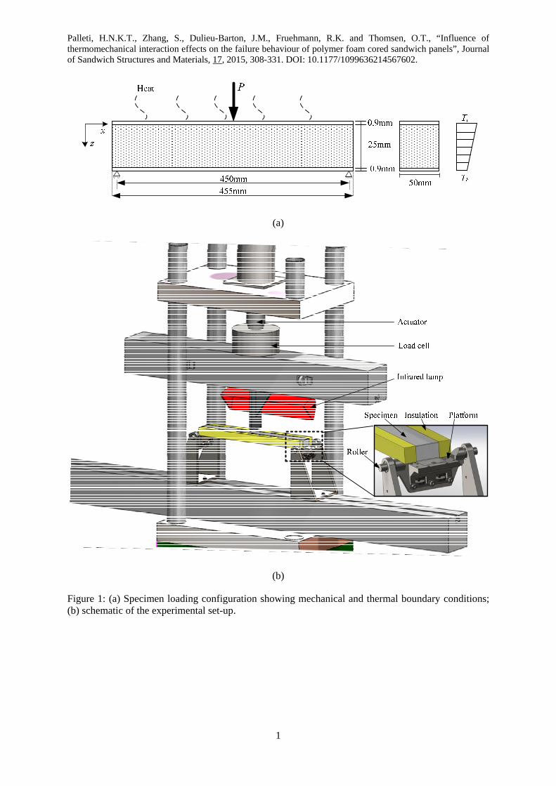
studies presented in [12, 15]. Figure 1(a) shows the dimensions and geometry of the foam
cored sandwich beam configuration used throughout the work described in the paper. Figure
1(b) shows the experimental set up in a standard servo-hydraulic test machine; a detailed
description of the experimental set up is given later in the paper.
The experiments are conducted over a range of temperatures from room temperature (25°C)
to below the glass transition temperature of the polymer foam core (70°C). Digital image
correlation (DIC) is used to obtain the local displacement field in the sandwich beam, and the
temperature is monitored using an infrared detector and thermocouples. The results are
compared with the predictions of both nonlinear FE analyses and the HSAPT approach
proposed in [12, 15], which includes geometric nonlinearity and thermal
degradation/reduction of the foam core elastic properties. Finally, nonlinear FE analyses that
account for orthotropic material nonlinearity (i.e. plasticity) as well as geometric nonlinearity
are conducted to further understand the failure of foam cored sandwich beams at room
temperature (25°C) subjected to three-point bending.
2 Test specimens and definition of material properties
The sandwich beams were made using a 25 mm thick PVC foam core (Divinycell H100
manufactured by DIAB, Sweden) and a 0.9 mm thick aluminium alloy face sheet (AA6082-
T6). The face sheets were bonded to the core using Prime 20 LV, a low viscosity epoxy resin
manufactured by Gurit. The adhesive was cured under uniform pressure inside a vacuum bag
Palleti, H.N.K.T., Zhang, S., Dulieu-Barton, J.M., Fruehmann, R.K. and Thomsen, O.T., “Influence of thermomechanical interaction effects on the failure behaviour of polymer foam cored sandwich panels”, Journal of Sandwich Structures and Materials, 17, 2015, 308-331. DOI: 10.1177/1099636214567602.
5
to produce a minimal thickness and uniform bond layer with low void content. Sandwich
beam specimens of 455 × 50 × 26.8 mm (length × width × thickness) were cut from a larger
panel and subjected to three-point bending with simply supported ends, as shown in Figure 1
(the sandwich beam span is 450 mm). The dimensions of the sandwich beam were selected to
fit the constraints of the test machine, the requirement to ensure a uniform temperature across
the length and width and to meet practical considerations with regard to spatial resolution of
the thermal and displacement measurements. The aluminium alloy was chosen for the face
sheet as its very high thermal conductivity promotes a uniform temperature distribution
throughout the face sheet and hence across the top surface of the foam core. Also, the
aluminium alloy has a minimal loss of stiffness over the temperature range from 25 to 100°C
[17].
Six ‘dog bone’ samples, with a gauge area of 50 × 12.5 mm, were cut from the aluminium
sheet used for the face sheets to obtain the room temperature stress-strain behaviour. DIC [18]
was used to obtain the strains parallel and transverse to the loading direction. The test
specimens were constructed so that the material behaviour to failure could be obtained both
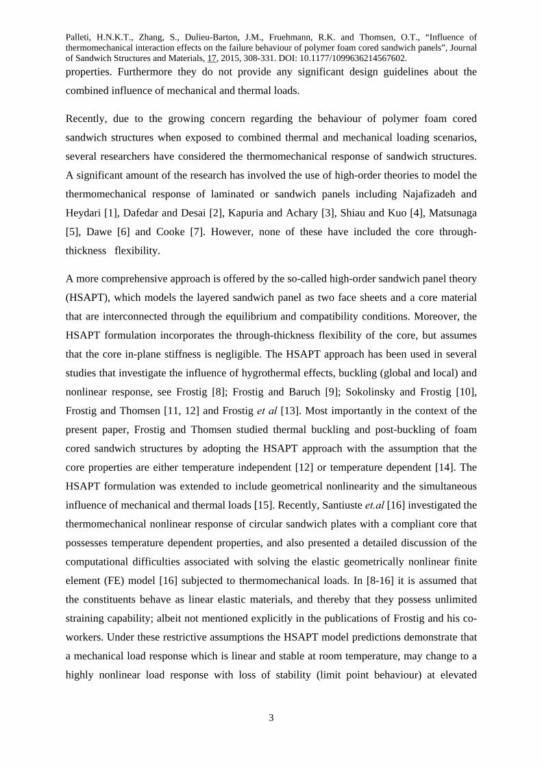
parallel and transverse to the sheet rolling direction. A typical stress-strain curve for the
aluminium alloy specimens loaded in the rolling direction is shown in Figure 2(a). The scatter
in the six tests was less than 0.5% for both the Young’s modulus and the 0.2% offset proof
stress.
Divinycell H100 foam core material is of medium density and was chosen as it is
representative of a large range of PVC foam cores. Detailed characterisation of the elastic
properties of the H100 foam has been conducted over a range of temperatures from 20 to
90°C using ASTM standard test specimen geometries [19, 20]. H100 foam has been shown to
be orthotropic, with a greater stiffness in the through-thickness direction. The full failure
envelope in tension and shear has been obtained at 25°C using a modified Arcan rig as
described in [21]. The stress-strain curves are presented in Figure 2(b), where the stress-strain
curve in compression at 25°C was obtained for the work presented in this paper using a
further development of the modified Arcan rig described in [21].
The nonlinear FE analyses were conducted using the software package ABAQUS/Standard
ver. 6.10 [22]. To implement the material data in the nonlinear FE model, a number of
assumptions and simplifications have been made. The face sheet elastic behaviour is defined
in terms of the Young’s modulus ( fE ) and Poisson’s ratio ( f ). These are assumed to be

Palleti, H.N.K.T., Zhang, S., Dulieu-Barton, J.M., Fruehmann, R.K. and Thomsen, O.T., “Influence of thermomechanical interaction effects on the failure behaviour of polymer foam cored sandwich panels”, Journal of Sandwich Structures and Materials, 17, 2015, 308-331. DOI: 10.1177/1099636214567602.
6
independent of temperature. The elastic response of the core is modelled using the Young's
moduli ( cE1 and cE2 ), the shear moduli ( cG12 ) and the major Poisson’s ratio ( c12 ). The
material orientation 1 is in the through-thickness direction (z in Figure 1), and orientation 2 is
the foam in-plane direction (x direction in Figure 1). Room temperature (25⁰C) properties of
the aluminium alloy face sheet and the foam core are listed in Table 1. The properties for the
aluminium are given in the sheet rolling direction only, as the differences in the elastic
properties parallel and transverse to the sheet rolling direction were found to be negligible.
Note that the coefficient of thermal expansion (CTE) in Table 1 is given as an isotropic
parameter. Manufacturers data giving separate values in the 1 and 2 directions is not available.
Table 1: Elastic properties of AA6082-T6 and Divinycell H100 at room temperature
Material E1 (MPa) E2 (MPa) G12 (MPa) ν12 CTE (K-1)
AA6082-T6 71000 (± 0.21%) - - 0.30 (± 5%) 23 x10-6 [23]
Divinycell H100 132 [19] 59 [19] 32 [20] 0.40 [19] 35 x10-6 [24]
CTE is the coefficient of linear thermal expansion.
In the nonlinear FE model, plasticity is defined in terms of a multilinear approximation of the
full stress-strain curves for both the aluminium alloy face sheets and the polymer foam core
material. Isotropic yielding behaviour is assumed for the face sheets, and the von Mises
yielding theory [25] is adopted for conducting the nonlinear FE analyses. Accordingly, the
yield stress for the face sheets, below which the plastic strain is zero, is defined. After this the
transition from the elastic to elasto-plastic material range is defined using a set of yield stress
terms ( f ) and plastic strain terms ( plf ) that depend on the chosen multi-linear elasto-plastic
stress-strain relationship. Yielding of the polymer foam core is defined using Hill’s
anisotropic plasticity theory [25] where the plastic potential or yield criterion is a general
extension of von Mises yield criterion as defined by the following expression:
1222)()()()(2 222222 xyzxyzzyzyzyij NMLHGFf (1)
where F, G, H, L, M and N are material parameters that may be obtained from experiments
and are defined as follows:
Palleti, H.N.K.T., Zhang, S., Dulieu-Barton, J.M., Fruehmann, R.K. and Thomsen, O.T., “Influence of thermomechanical interaction effects on the failure behaviour of polymer foam cored sandwich panels”, Journal of Sandwich Structures and Materials, 17, 2015, 308-331. DOI: 10.1177/1099636214567602.
7
211
233
222
211
233
222
20 111
2
1111
2 RRRF
(2)
222
211
233
222
211
233
20 111
2
1111
2 RRRG
(3)
211
233
222
233
222
211
20 111
2
1111
2 RRRH
(4)
223
2
23
0
2
3
2
3
RL
(5)
213
2
13
0
2
3
2
3
RM
(6)
212
2
12
0
2
3
2
3
RN
(7)
where ii or ij are the measured yield stress values when the material is subjected to only
ii or ij stresses, respectively (i.e., in uniaxial normal or pure shear stress states), 0 is the
chosen reference yield stress specified for the plasticity definition, 3/00 , and ijR are
the stress ratios defined below:
00
ij
ijii
ii RandR (8)
In simple terms, Eq. (8) defines the amount of orthotropic plasticity developed relative to the
chosen reference plasticity ( 0 and 0 ) defined in one material direction. The plastic strain
pl is obtained using the associated plasticity flow rule [22, 25] i.e.
bf
dfdd pl
(9)
where dλ is a proportionality factor and b is derived from Eq. (1) to give the following [22]:
Palleti, H.N.K.T., Zhang, S., Dulieu-Barton, J.M., Fruehmann, R.K. and Thomsen, O.T., “Influence of thermomechanical interaction effects on the failure behaviour of polymer foam cored sandwich panels”, Journal of Sandwich Structures and Materials, 17, 2015, 308-331. DOI: 10.1177/1099636214567602.
8
yz
zx
xy
xzzy
yxzy
yxxz
L
M
N
GF
HF
HG
b
2
2
2
)()(
)()(
)()(
(10)
The above outlines how a general multi-axial plastic strain state in an orthotropic core
material is evaluated using Hill’s anisotropic plasticity theory. More details about the
implementation of the plasticity model can be found in [22, 25]. For the practical
implementation of the plasticity model in ABAQUS, a set of yield stresses and plastic strains
in one material orientation ( c and plc , similar to isotropic yielding) are defined to represent
the reference yield stresses 0. In addition, Hill’s stress ratios R11, R22, R12, R13 and R23
(considering the core is transversely isotropic according to [20, 21]) that define plasticity of
the core in the other material directions are defined see Eq. (8) and Ref. [25].
According to the above, the definition of material behaviour of the face sheets at a given
temperature therefore requires two elastic material constants ( fE , f ) and m parameters for
the plasticity definition (set of f and pl
f ), where m is the number of separation points used
in the multi-linear approximations of the stress strain curves. For example, for a bi-linear
approximation of the face sheet m = 2 and only two values of f and plf are required. For
the particular investigation presented in this paper a six segment approximation was used for
the aluminium face sheets (m = 6) as shown in Figure 2(a), overlaid on the experimentally
derived stress-strain curve. For defining the material behaviour of the transversely isotropic
polymer foam core, 5 elastic constants ( cE1 , cE2 , c12 , cG12 , cG23 ) are required, n parameters
are required for the plasticity definition (set of c and plc ), and four stress ratios ( 11R , 22R ,
12R , 23R ). Thus, a total of (2 + m) material parameters for the face sheets, and (9 + n) material
parameters for the core, are required at any given temperature to define the elasto-plastic
material behaviour in the nonlinear FE model.
The core is more susceptible to yielding when subjected to compressive stresses than to
tensile stresses. Thus, in all the cases considered core material yielding and subsequent
failure (fracture) was triggered by either core compression (leading to crushing) or core shear,

Palleti, H.N.K.T., Zhang, S., Dulieu-Barton, J.M., Fruehmann, R.K. and Thomsen, O.T., “Influence of thermomechanical interaction effects on the failure behaviour of polymer foam cored sandwich panels”, Journal of Sandwich Structures and Materials, 17, 2015, 308-331. DOI: 10.1177/1099636214567602.
9
rather than tensile core stresses. Accordingly, the Bauschinger-like effect [26] can be
neglected for the present loading cases. Thus, it is assumed that Hill’s anisotropic yielding
theory can be used with the compression stress-strain curve shown in Figure 2(b) adopted for
the definition of the elasto-plastic material behaviour of the polymer foam. Also it was
assumed from the compressive stress-strain curve shown in Figure 2(b) that there are no
plastic deformations in the core up to 1.5 MPa ( c ).
3 Experimental procedure
The boundary conditions encompass two aspects, mechanical and thermal, as shown in
Figure 1. The mechanical load was introduced using a servo-hydraulic test machine via a 12
mm diameter steel roller in the centre and simply supported at the ends. The sandwich beam
ends overhung the support by 2.5 mm. As the specimen was loaded images were captured
with a 5 mega pixel LA Vision VC-imager E-lite digital camera (with a frame rate of 2 Hz)
with a 105 mm Sigma lens, and DIC was used to obtain the displacement during the loading.
For the purpose of DIC, the side of the specimen was sprayed with black and white paint to
form a random speckle. The DIC algorithm then tracks the movement of the speckles relative
to a reference image, thereby providing a full-field map of the surface deformations from
which both strains and point measurements of displacement were obtained. Images of the side
surface of the beam specimen were recorded synchronously with the load data. DIC was
performed using the commercially available software Davis 7.4 [27] by LaVision. The image
captured at zero load was used as the reference image and the subset size was 64 × 64 pixel.
The displacement accuracy was verified as about 0.02 pixel by performing image correlation
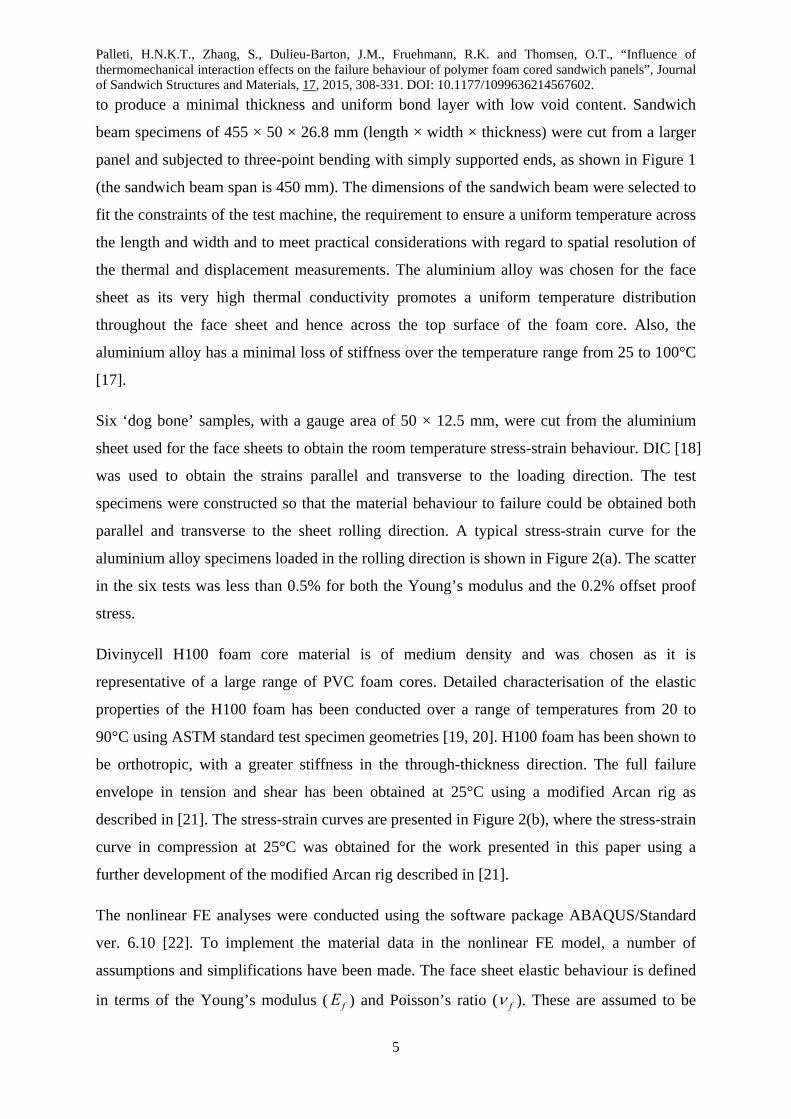
between two images at zero load. A typical displacement field obtained using DIC is shown
in Figure 3. It is seen that the largest displacement occurs at the mid-span, and the
displacement decreases symmetrically towards the two ends of the specimen.
A through-thickness temperature gradient was achieved by heating the upper surface of the
specimen using an infrared (IR) radiator (see Figure 1(b)), while maintaining the lower face
sheet at ambient temperature by means of forced convection of the air below the specimen
using an electric fan. This method of creating a temperature gradient was selected because it
provides a non-contact solution that replicates heating through solar radiation. One challenge
in achieving thermal boundary conditions that can be represented in a two dimensional FE or
HSAPT models (that analyses sandwich beams or 2D panels), is the finite width of the
specimen, which leads to a non-uniform temperature distribution across the specimen width
Palleti, H.N.K.T., Zhang, S., Dulieu-Barton, J.M., Fruehmann, R.K. and Thomsen, O.T., “Influence of thermomechanical interaction effects on the failure behaviour of polymer foam cored sandwich panels”, Journal of Sandwich Structures and Materials, 17, 2015, 308-331. DOI: 10.1177/1099636214567602.
10
due to heat losses at the specimen sides. However, the two dimensional FE or HSAPT models
necessarily assume a constant temperature across the width. To reduce the width-wise
temperature gradient, insulation in the form of additional PVC foam was placed on both sides
of the specimen during the heating process (see Figure 1(b)). Due to the space available in
the test rig, the practical limit on the width of the insulation was approximately 25 mm.
To assess the temperature distribution (especially across the specimen width) a combination
of IR thermography (to obtain surface temperature distributions) and thermocouples (to
obtain internal temperature distributions) was used. In these initial investigations a 30 mm
thick Divinycell H100 foam core was used. To facilitate the introduction of the
thermocouples, 2 mm diameter holes were drilled into the core material at various locations;
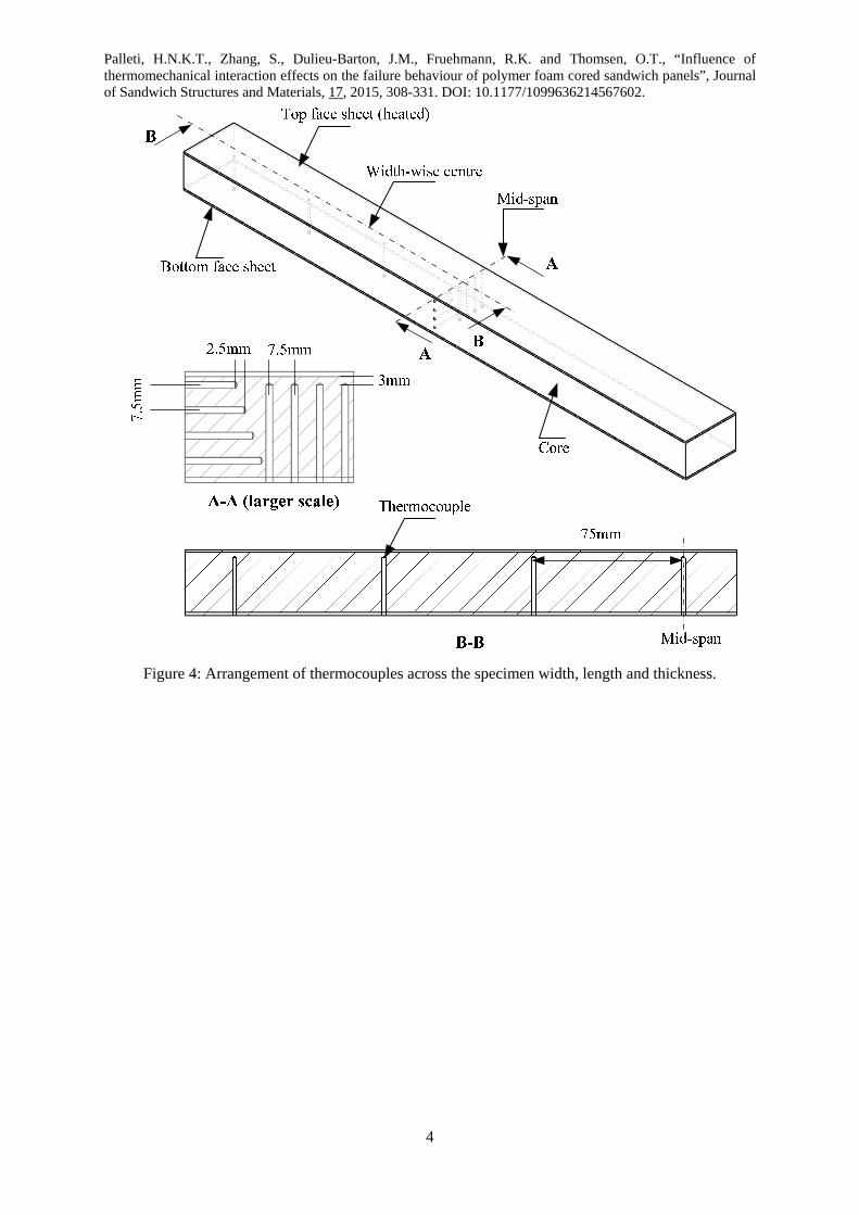
these are shown in Figure 4. To measure the temperature distribution across the specimen
width, four holes were drilled through the bottom face sheet to nominal depth of 3 mm below
the upper face sheet and spaced 7.5 mm apart across the width of the specimen at the mid-
span. To measure the temperature distribution along the specimen length, a further three
holes were drilled at 75 mm intervals along the specimen length on the width-wise central
axis. To measure the through-thickness temperature distribution four more thermocouples
were also placed 7.5 mm apart through the thickness of the core. The holes for these were
drilled through the core material from the side of the specimen starting at 3 mm below the top
face sheet to 4.5 mm from the bottom face sheet, laterally offset by 2.5 mm across the
specimen width. The lateral offset was introduced to reduce the effect of the upper holes on
the heat transfer from the top face sheet to lower holes that would occur if all the holes were
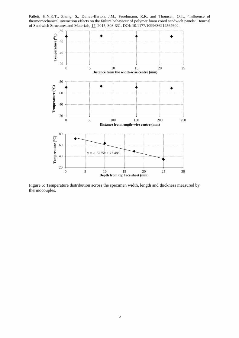
drilled to the same depth. The temperature measurements from each of the three sets of the
thermocouples are shown in Figure 5 for a top surface temperature of 80°C. It can be seen
that the temperature distribution along the specimen length and across the width is practically
uniform, with up to 4°C difference between the mid-plane and the specimen edge. The
temperature distribution through the core thickness is approximately linear.
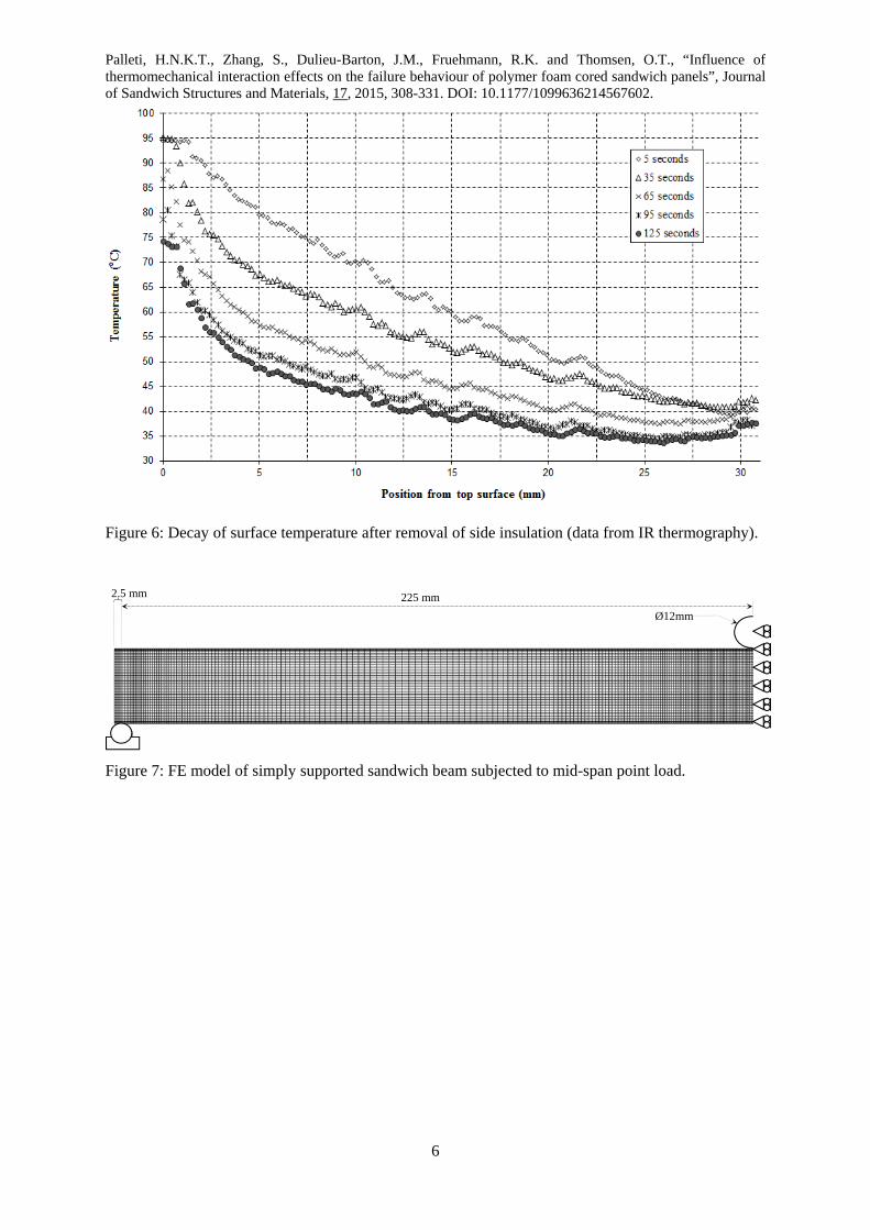
The through-thickness temperature profile was also assessed using IR images of the specimen
side using a Silver 480M detector with a 320 × 256 pixel indium antimonide cooled detector,
manufactured by Cedip Infrared Systems. Figure 6 shows the through thickness temperature
profile on the specimen side immediately after removal of the insulation, when the top face
sheet was heated to 95oC. Note that the temperature through the 0.9 mm thick face sheets
remains approximately uniform due to the high thermal conductivity of the aluminium. At
first the profile through the thickness of the foam is roughly linear as assumed in the

Palleti, H.N.K.T., Zhang, S., Dulieu-Barton, J.M., Fruehmann, R.K. and Thomsen, O.T., “Influence of thermomechanical interaction effects on the failure behaviour of polymer foam cored sandwich panels”, Journal of Sandwich Structures and Materials, 17, 2015, 308-331. DOI: 10.1177/1099636214567602.
11
modelling, with a similar through thickness gradient as given by the thermocouples in Figure
5. Over time, the through thickness profile becomes nonlinear due to cooling at the specimen
edges. As a result, the temperature distribution across the specimen width becomes non-
uniform. Equilibrium was reached roughly 2 minutes after the insulation was removed. As
the insulation must be removed to enable the specimen side to be observed for DIC, it is
imperative that the loading is conducted quickly while the temperature gradient is still close
to linear, preferably in less than 30 seconds. A set of initial tests indicated that failure
occurred after no more than 10 mm displacement. Hence a 20 mm/min loading rate was
selected to collect the white light images for the DIC.
In summary the following test methodology was defined:
1. The specimen was positioned on the simply supported three-point bending jig. One
image of the side surface with a speckle pattern was recorded as the reference position
of the specimen.
2. The insulation was positioned at the side surface of the specimen. The top face sheet
was heated to the required temperature and held until a steady temperature state was
achieved and the specimen was allowed to expand freely under the thermal loading.
3. The insulation was removed on one side to enable images of the specimen
deformation to be obtained.
4. The load was applied in displacement control at a rate of 20 mm/min until the
specimen failed. Images of the specimen side surface with a speckle pattern and the
load were recorded at 2 Hz.
4 Elastic behaviour of sandwich beams at elevated temperatures
The response of the foam cored sandwich beam assuming linear elastic material properties
and including geometric nonlinearity and thermal degradation of the core is analysed using
the HSAPT approach discussed previously [15]. In addition, an approximate 2D elastic FE
analysis of half of the sandwich beam with symmetry boundary conditions imposed at the
mid-span was conducted using the FE analysis software package, ABAQUS/Standard ver.
6.10 [22]. Figure 7 shows the final FE mesh used in the half span beam model, which was the
result of an elaborate mesh convergence study. The issues and difficulties concerning the
correlation between HSAPT predictions and fully converged nonlinear FE results are
discussed in detail by Santiuste et al. [16] and Palleti et al. [28]. Generally it is found that
nonlinear FE models that assume linear elastic material behaviour (and infinite straining

Palleti, H.N.K.T., Zhang, S., Dulieu-Barton, J.M., Fruehmann, R.K. and Thomsen, O.T., “Influence of thermomechanical interaction effects on the failure behaviour of polymer foam cored sandwich panels”, Journal of Sandwich Structures and Materials, 17, 2015, 308-331. DOI: 10.1177/1099636214567602.
12
capability) but include geometric nonlinearity (i.e. large displacements and moderate
rotations) yield predictions that correlate well with HSAPT model results.
In accordance with [16, 28] the nonlinear FE model was based on the following restrictive
assumptions:
1. The polymer core material is linear elastic (and implicitly assumed has infinite
straining capability) and orthotropic with properties varying with temperature in
accordance with [19, 20].
2. The face sheets are linear elastic and isotropic, and the material properties are further
assumed to be independent of temperature.
3. The roller through which the load is applied to the top face sheet is modelled as a
rigid body.
4. The outer support (see Figure 7) is modelled as a vertical (z-direction) displacement
constraint applied to a single point on the bottom face sheet, whereas no constraints
are imposed in the horizontal direction. (It is important to include the overhang at the
beam end to avoid excessive deformations resulting from the approximation of the
support as a point constraint.)
5. It is assumed that the face sheets are perfectly bonded to the core.
6. The strain rate is assumed to be sufficiently low so that strain rate effects in the
material behaviour of the core can be ignored.
7. Geometric nonlinearity is included in the model.
The FE model is informed with the measured equilibrium temperatures in accordance with
the corresponding thermal gradients obtained in the experiments. The thermal gradient is
applied only through the core, while the temperature through the thickness of the face sheet is
assumed to be uniform in accordance with the temperature field measured at the specimen
edge using the IR detector, as shown in Figure 6. Furthermore, the variation of temperature is
assumed be constant across the width and along the length of the beam. The FE model
contains 4 elements through the face sheet thickness and 20 elements through the core
thickness. 8-noded plane stress quadratic elements with reduced integration (CPS8R) are used.
Mesh refinement is provided in the vicinity of load introduction at mid-span and near the
supports (as shown in Figure 7). A mesh convergence study was performed demonstrating
convergence (stiffness – peak displacements) when a total of 6256 elements are used with
736 elements in each face sheet and 4784 elements in the core. The first step is to assess the
Palleti, H.N.K.T., Zhang, S., Dulieu-Barton, J.M., Fruehmann, R.K. and Thomsen, O.T., “Influence of thermomechanical interaction effects on the failure behaviour of polymer foam cored sandwich panels”, Journal of Sandwich Structures and Materials, 17, 2015, 308-331. DOI: 10.1177/1099636214567602.
13
accuracy of the geometrically linear and linear elastic FE model by comparing its predictions
with experimental results. It has already been established that converged geometrically
nonlinear and elastic FE models provide predictions that are in excellent agreement with
HSAPT model predictions [16, 28]. Accordingly, the main emphasis in the following
discussion will be on the experimental observations and their correlation with nonlinear FE
results.
Figure 8 shows the measured deflections of the top face sheet at mid-span vs. applied load at
three upper face sheet temperatures of 25C, 50C and 70C. The bottom face sheet is at
25°C in all these cases. It is observed that the initial sandwich beam bending stiffness
predicted by the FE analysis matches the experimentally obtained stiffness for all the three
upper face sheet temperatures. However, in the experiments it is seen that the load vs.
deflection of the top face sheet at mid-span relation displays a linear trend until the load
suddenly drops. The reason for this is that face sheet indentation and core crushing occurred
followed by face-core debonding, as depicted in Figure 9 for a sandwich beam specimen
subjected to a temperature of 50C. Thus, the nonlinear behaviour predicted by HSAPT
(driven by geometric nonlinearity combined with a reduction of core stiffness with increasing
temperature), was in all cases preceded by face sheet indentation and core crushing triggered
by nonlinear material behaviour (plasticity). This behaviour cannot be captured by the
geometrically nonlinear/elastic (with infinite straining capability) FE analyses. Here a linear
load-deflection behaviour is predicted until distinctly nonlinear response characteristics are
observed for a top face sheet mid-span deflection of around 20 mm. The nonlinearity is
associated with the formation of local mid-span wrinkles in the upper face sheet as the core
material softens due to the increasing temperature and loses its ability to support the face
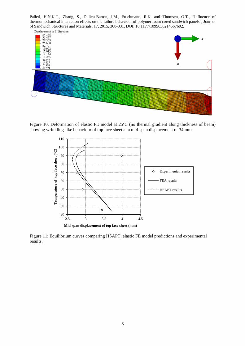
sheet. Figure 10 shows that top face sheet wrinkling is even predicted to occur at room
temperature (25°C) and without a through-thickness thermal gradient but for very large
displacements. The wrinkle deformation results in a complete loss of the load carrying
capability of the upper face sheet that is stabilized through and by the core, which leads to a
progressive loss of overall sandwich beam bending stiffness with increasing mid-span load.
The behaviour is in close agreement with HSAPT predictions [15], and if the nonlinear FE
solution procedure is continued by additional load increments, the geometrically
nonlinear/elastic HSAPT and FE solutions will eventually predict loss of stability (reduction
in stiffness). Comparing the experimental observations with the geometrically
nonlinear/elastic FE results it is seen that indentation failure occurred at less than 25% of the
Palleti, H.N.K.T., Zhang, S., Dulieu-Barton, J.M., Fruehmann, R.K. and Thomsen, O.T., “Influence of thermomechanical interaction effects on the failure behaviour of polymer foam cored sandwich panels”, Journal of Sandwich Structures and Materials, 17, 2015, 308-331. DOI: 10.1177/1099636214567602.
14
load at which a nonlinear load response is predicted. Hence, to provide numerical predictions
that capture the failure mode, load response and failure load accurately, it is necessary to
include material nonlinearity in the FE modelling.
Interestingly, a comparison of the mid-span deflections at different temperatures for a mid-
span load of 800 N shows a very similar trend between the predictions of both the FE and
HSAPT model and the experimental observations see Figure 11. At this mid-span load, the
sandwich constituent materials are still within the elastic limit. The top face sheet mid-span
deflection is measured relative to the room temperature equilibrium condition and therefore
includes the deflection/deformation due to thermal expansion. Hence, as the temperature of
the top face sheet is increased from 25 to 70°C while maintaining the bottom face sheet at
25°C, a decrease in the top-face sheet displacement is recorded. Then at 90°C there is a
sudden increase in displacement. However, the situation at 90°C is further complicated by
effects of crossing the glass transition temperature of the PVC foam. For this reason, the
current work has focused only on tests conducted up to 70°C.
5 Influence of core and face sheet material nonlinearity on sandwich beam behaviour at
room temperature (25°C)
The FE model described in section 4 is extended by the inclusion of material nonlinearity
through the adoption of Hill’s anisotropic plasticity theory [22], and by representing the
multi-axial stress-strain behaviour of the polymer core and face sheet materials by multi-
linear approximations of the stress-strain curves, as described in section 2. The converged FE
mesh, loading and boundary conditions remain as shown in Figure 7.
The comparison of the fully nonlinear FE model predictions, that includes both geometric and
material nonlinearity, with the experimental results has been conducted only for room
temperature (25°C) as accurate material properties at elevated temperatures are not available
for the foam core. The comparison is shown for both the top and bottom face sheet
displacements in Figure 12. The FE model is seen to slightly under predict the stiffness and
ultimate load, but the discrepancy in the ultimate load is only 4.8% relative to the
experimental value and 5.1% w.r.t. the predicted initial stiffness. Also, the predicted failure
mode, i.e. crushing of the core and corresponding indentation involving extensive face sheet
plasticity, agrees well with the experimental observations, and also the predicted indentation
depth (see image in Figure 9) agrees well with the experimental results as can be seen in

Palleti, H.N.K.T., Zhang, S., Dulieu-Barton, J.M., Fruehmann, R.K. and Thomsen, O.T., “Influence of thermomechanical interaction effects on the failure behaviour of polymer foam cored sandwich panels”, Journal of Sandwich Structures and Materials, 17, 2015, 308-331. DOI: 10.1177/1099636214567602.
15
Figure 12. The deformation field obtained from the nonlinear FE model, verifying the
observed indentation behaviour, is shown in Figure 13.
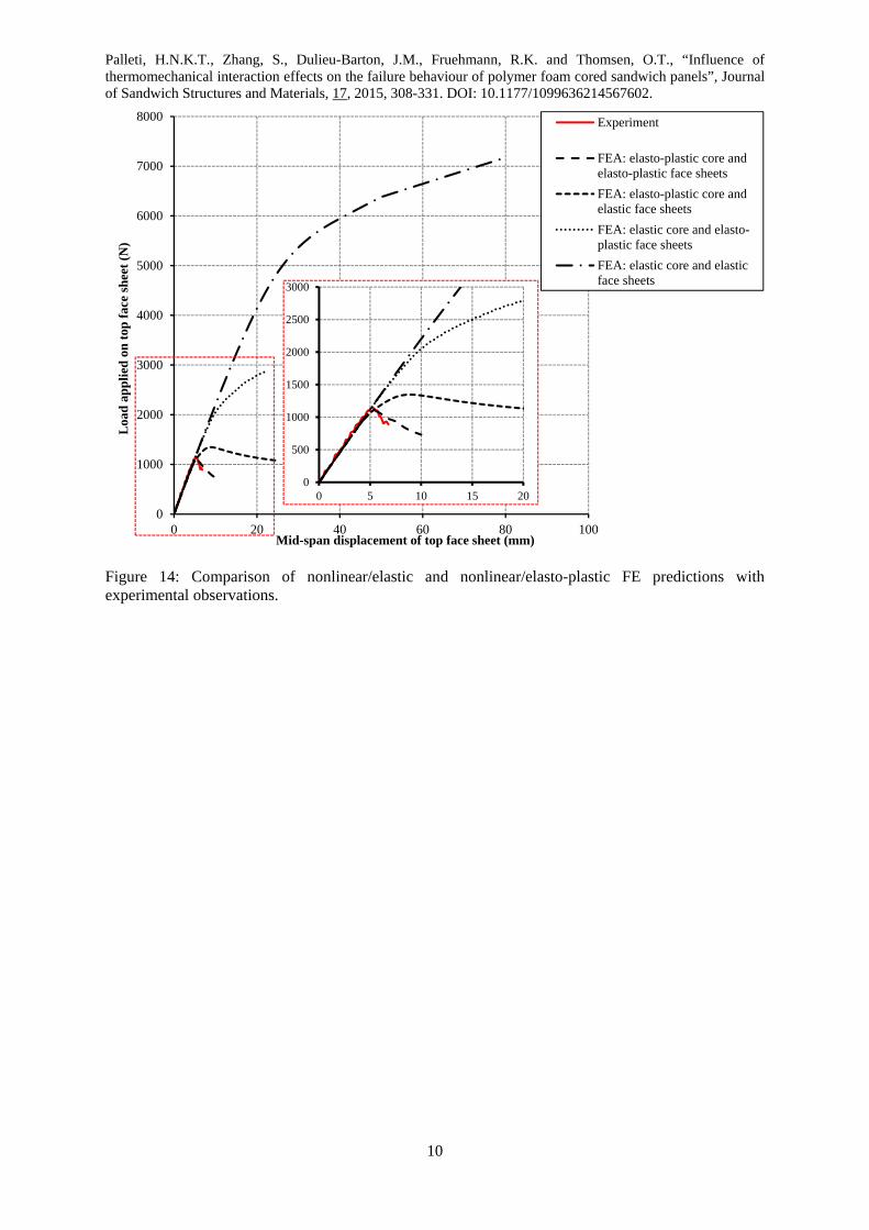
The influence of the core and face sheet material nonlinearity on the load-deflection
behaviour at room temperature (25C) at mid-span of the upper face sheet is provided in
Figure 14. It can be seen that the nonlinear elasto-plastic FE model shows excellent
correspondence with the experimental data. When the material nonlinearity of the face sheet
material is included in the modelling, but the core is assumed to be linear elastic, it is
observed that the load at which significant nonlinear behaviour initiates reduces by about 50%
compared to the nonlinear/elastic FE predictions (from roughly 4000 N to 2000 N). When the
face sheets are considered to behave linear elastically and the core material
nonlinearity/plasticity is included the load where the response changes from being linear to
distinctly nonlinear reduces to about 1000 N and a peak load (failure load) of about 1300 N is
obtained. This is very close to the experimental observations and the predictions of the fully
nonlinear elasto-plastic FE model results (long dashed lines) which show a transition from
linear to nonlinear response at a load of roughly 1000 N and a peak (failure) load of about
1100 N. The results clearly indicate that failure is dominated by the through-thickness normal
stress in the core. Moreover, the comparative analysis results presented in Figure 14 also
highlights that the nonlinear interaction effects, driven by geometric nonlinearity that cause a
progressive loss of stiffness (and which may lead to loss of stability), predicted by the
HSAPT model greatly exceed the loads that can be sustained by typical engineering materials
and typical sandwich beam geometries. In other words, the limits of material elasticity (in
both the core and the face sheets) are reached long before geometric nonlinearity becomes an
issue for the considered three-point bending example.
6 Discussion and Conclusions
An experimental methodology has been developed that allows the simultaneous application
of mechanical loading and a well defined thermal field (homogeneous in length and width
directions and with a linear gradient through the thickness). DIC was used to assess the local
displacement field of the sandwich beam and the temperature was monitored using an
infrared detector and thermocouples. A series of three experiments has been conducted for a
foam cored sandwich beam with aluminium face sheets, and the experimental observations
have been compared with numerical results obtained using nonlinear FE analysis as well as

Palleti, H.N.K.T., Zhang, S., Dulieu-Barton, J.M., Fruehmann, R.K. and Thomsen, O.T., “Influence of thermomechanical interaction effects on the failure behaviour of polymer foam cored sandwich panels”, Journal of Sandwich Structures and Materials, 17, 2015, 308-331. DOI: 10.1177/1099636214567602.
16
analytical results based on the so-called High-Order Sandwich Panel Theory (HSAPT) [12,
15, 16].
It has been demonstrated, for the case of a foam cored sandwich beam in three-point bending,
that making similar assumptions regarding the material models (i.e. assuming linear elastic
material behaviour and unlimited straining capability), the FE and HSAPT models compare
very closely. The comparison of the FE model with experiments thereby demonstrates that
the key short coming of the HSAPT model, as presented in e.g. [15], lies in its inherent
assumptions regarding linear elasticity and unlimited straining capability of the materials. For
the case considered, three interacting failure modes which lead to the final collapse of the
sandwich beam are observed from the experiments: failure (yielding) of the top face sheet,
failure (yielding) of the core and failure (debonding) of the interface. By considering the face
sheets and the core in turn, it has been shown that both materials are expected to fail at much
smaller loads/deflections than those required to provoke the predicted geometrically driven
nonlinearity.
The nonlinear thermomechanical interaction effects, which may change a linear and stable
load response of a sandwich structure into becoming nonlinear and unstable as predicted by
the HSAPT models [12, 15, 16], have been shown to be very difficult to trigger in a
laboratory test setup involving the application of localised/concentrated mechanical loading
and thermally induced deformations. Thus, in all the experiments, failure of the core
dominated. This can be ascribed to two aspects of the chosen three-point bending test
configuration. On the one hand, the geometry of the specimen (length to thickness ratio)
favours the core shear failure mode. On the other hand the concentrated through-thickness
load at mid-span in the three point test will promote compressive failure (crushing) of the
core, inducing localised face sheet yielding. For this reason, most sandwich structures are
designed to sustain a combination of in-plane and distributed lateral loads. Through-thickness
point loading, as applied in the three-point bend test, is typically avoided either combined
with some means of spreading the load, by means of inserting a local reinforcement of the
face sheet.
It is shown that nonlinear thermomechanical interaction effects in foam cored sandwich
structures leading to the risk of loss of stability, especially at elevated temperatures, can and
do indeed occur in realistic shell or plate sandwich structures subjected to distributed pressure
loading (which is the typical loading type for which sandwich structures are designed).

Palleti, H.N.K.T., Zhang, S., Dulieu-Barton, J.M., Fruehmann, R.K. and Thomsen, O.T., “Influence of thermomechanical interaction effects on the failure behaviour of polymer foam cored sandwich panels”, Journal of Sandwich Structures and Materials, 17, 2015, 308-331. DOI: 10.1177/1099636214567602.
17
Furthermore the nonlinear behaviour in most realistic cases will involve some influence of
material nonlinearity, even for the case with smoothly distributed external loading.
Accordingly, a realistic prediction of the complex nonlinear response of thermomechanically
loaded foam cored sandwich structures must include the interactions between geometric
nonlinearity, material nonlinearity, thermally induced deformations and
degradation/reduction of the material properties at elevated temperatures. The HSAPT
approach in principle can be expanded to account for this, and it would be valuable to further
develop this approach at least for some bench mark cases, albeit the mathematical complexity
in doing so will be considerable. For more general cases, converged fully nonlinear FE
solution procedures are likely to provide more easily attainable and reproducible predictive
results.
Model predictions involving very complex thermomechanical interaction effects should be
validated through experiments. In doing so, and with the objective of triggering a load
response that displays significant influence of geometric nonlinearity and thermomechanical
interaction effects, a realistic test should be designed so that distributed mechanical loading
can be imposed in a well defined manner along with well defined geometric boundary
conditions and a well defined thermal field.
Acknowledgements
The work presented was co-sponsored by the Danish Council for Independent Research |
Technology and Production Sciences (FTP), Grant Agreement 274-08-0488, “Thermal
Degradation of Polymer Foam Cored Sandwich Structures”, the Chinese Scholarship Council,
and the US Navy, Office of Naval Research (ONR), Grant Award N000140710227. The
ONR programme manager was Dr. Yapa D. S. Rajapakse. The financial support received is
gratefully acknowledged.
The authors are grateful to DIAB for providing the foam core material used in this paper and
for their input into the project.
The compressive testing of PVC H100 foam core material leading to a full stress-strain curve
to failure used in this work was conducted by S.T. Taher, Department of Mechanical and
Manufacturing Engineering, Aalborg University, Denmark.
Palleti, H.N.K.T., Zhang, S., Dulieu-Barton, J.M., Fruehmann, R.K. and Thomsen, O.T., “Influence of thermomechanical interaction effects on the failure behaviour of polymer foam cored sandwich panels”, Journal of Sandwich Structures and Materials, 17, 2015, 308-331. DOI: 10.1177/1099636214567602.
18
References
1. Najafizadeh M.M., Heydari H.R., 2004, Thermal buckling of functionally graded circular
plates based on higher order shear deformation plate theory. European Journal of
Mechanics - A/Solids, 23(6):1085-1100.
2. Dafedar J., Desai Y., 2002, Thermomechanical buckling of laminated composite plates
using mixed, higher-order analytical formulation. Journal of Applied Mechanics-
Transactions of the Asme, 69(6):790-799.
3. Kapuria S., Achary G., 2004, An efficient higher order zigzag theory for laminated plates
subjected to thermal loading RID C-5368-2008. Int J Solids Structures, 41(16-17):4661-
4684.
4. Shiau L., Kuo S., 2004, Thermal postbuckling behavior of composite sandwich plates. J
Eng Mech, 130(10):1160-1167.
5. Matsunaga H., 2005, Thermal buckling of cross-ply laminated composite and sandwich
plates according to a global higher-order deformation theory. Composite Structures,
68(4):439-454.
6. Dawe D.J., 2002, Use of the finite strip method in predicting the behaviour of composite
laminated structures. Composite Structures, 57(1-4):11-36.
7. Cooke G.M.E., 2004, Stability of lightweight structural sandwich panels exposed to fire.
Fire Mater, 28(2-4):299-308.
8. Frostig Y., 1997, Hygothermal (environmental) effects in high-order bending of
sandwich beams with a flexible core and a discontinuous skin. Composite Structures,
37(2):205-221.
9. Frostig Y., Baruch M., 1993, High-order buckling analysis of sandwich beams with
transversely flexible core. J Eng Mech, 119(3):476-495.
10. Sokolinsky V., Frostig Y., 2000, Branching behavior in the nonlinear response of
sandwich panels with a transversely flexible core. Int J Solids Structures, 37(40):5745-
5772.
11. Frostig Y., Thomsen O.T., 2005, Localized effects in the nonlinear behavior of sandwich
panels with a transversely flexible core. Journal of Sandwich Structures and Materials,
7(1):53-75.
12. Frostig Y., Thomsen O.T., 2008, Thermal buckling and postbuckling of sandwich panels
with a transversely flexible core. AIAA J, 46(8):1976-1989.
Palleti, H.N.K.T., Zhang, S., Dulieu-Barton, J.M., Fruehmann, R.K. and Thomsen, O.T., “Influence of thermomechanical interaction effects on the failure behaviour of polymer foam cored sandwich panels”, Journal of Sandwich Structures and Materials, 17, 2015, 308-331. DOI: 10.1177/1099636214567602.
19
13. Frostig Y., Thomsen O.T., Sheinman I., 2005, On the nonlinear high-order theory of
unidirectional sandwich panels with a transversely flexible core. Int. J Solids Structures,
42(5-6):1443-1463.
14. Frostig Y., Thomsen O.T., 2007, Buckling and nonlinear response of sandwich panels
with a compliant core and temperature dependent mechanical properties. J Mech Mater
Struct, 2(7):1355-1380.
15. Frostig Y., Thomsen O.T., 2008, Nonlinear thermal response of sandwich panels with a
flexible core and temperature dependent mechanical properties. Composites Part B-
Engineering 39(1):165-184.
16. Santiuste C., Thomsen O.T., Frostig Y., 2011, Thermomechanical load interactions in
foam cored axi-symmetric sandwich circular plates - High-order and FE models.
Composite Structures, 93(2): 369-376.
17. Robinson A., Dulieu-Barton J.M., Quinn S., Burguete R., 2013, The potential for
assessing residual stress using thermoelastic stress analysis: a study of cold expanded
holes. Experimental Mechanics, accepted, in press. .
18. Sutton M.A., Orteu J.-J., Schreier H.W., 2009, Image correlation for shape, motion and
deformation measurements. Springer Science and Business Media, New York.
19. Zhang S., Dulieu-Barton J.M., Fruehmann R.K., Thomsen O.T., 2012, A methodology
for obtaining material properties of polymeric foam at elevated temperatures.
Experimental Mechanics, 52(1):3-15.
20. Zhang S., Dulieu-Barton J.M., Thomsen O.T., 2015, The effect of temperature on the
failure modes of polymer foam cored sandwich structures. Composite Structures, 121,
104-113.
21. Taher S.T., Thomsen O.T., Dulieu-Barton J.M., Zhang S., 2011, Determination of
mechanical properties of PVC foam using a modified Arcan fixture. Composites Part A:
Applied Science and Manufacturing, 43(10): 1698-1708.
22. Abaqus 6.10 theory manual (PDF Documentation), Chapter 4 Material constitutive
theories - Stress potential for anisotropic metal plasticity, pp 4.3.3-1 – 4.3.3-3
23. Wilson A.J.C., 1941, The thermal expansion of aluminium from 0° to 650°C.
Proceedings of the Physical Society 53(3): 235.
24. DIAB datasheet. http://www.diabgroup.com/Sandwich-technology/Datasheets. Accessed
on 09/2012.
Palleti, H.N.K.T., Zhang, S., Dulieu-Barton, J.M., Fruehmann, R.K. and Thomsen, O.T., “Influence of thermomechanical interaction effects on the failure behaviour of polymer foam cored sandwich panels”, Journal of Sandwich Structures and Materials, 17, 2015, 308-331. DOI: 10.1177/1099636214567602.
20
25. Hill R., 1948, A theory of yielding and plastic flow of anisotropic metals, Proceedings of
the Royal Society of London Series A: Mathematical and Physical Sciences,
193(1033):281-297.
26. Bauschinger J., 1881, Über die Veränderung der Elastizitätsgrenze und des
Elastizitätsmoduls Verschiedener Metalle. Zivil ingenieur, 27:289-317.
27. LAVision. http://www.lavision.de/en/products/davis.php. Accessed on 09/2012
28. Palleti H.N.K.T., Thomsen O.T., Dulieu-Barton J.M., Frostig Y., Thermomechanical
interactions in polymer foam cored sandwich panels – correlation between high-order
sandwich panel theory and finite element analysis results. submitted.
Palleti, H.N.K.T., Zhang, S., Dulieu-Barton, J.M., Fruehmann, R.K. and Thomsen, O.T., “Influence of thermomechanical interaction effects on the failure behaviour of polymer foam cored sandwich panels”, Journal of Sandwich Structures and Materials, 17, 2015, 308-331. DOI: 10.1177/1099636214567602.
1
(a)
(b)
Figure 1: (a) Specimen loading configuration showing mechanical and thermal boundary conditions; (b) schematic of the experimental set-up.

Palleti, Hthermomof Sandw
Figure 2H100 fo
0
0.5
1
1.5
2
2.5
3
3.5
4
4.5
Str
ess
(MP
a)
H.N.K.T., Zhmechanical intewich Structure
2: Stress-straioam at 25°C u
0
hang, S., Dueraction effects and Materia
in data for (aunder tension
0.05
lieu-Barton, ts on the failu
als, 17, 2015, 3
a) AA6082-Tn and shear a
0.1
J.M., Fruehmure behaviour 308-331. DOI
2
(a)
(b)
T6 aluminiumaccording to
Strain (mm/m
mann, R.K. aof polymer foI: 10.1177/109
m alloy unde[21].
0.15mm)
Through
In-plane
Shear
Through
FEA inp
and Thomsenoam cored san996362145676
r tension and
0.2
h thickness tens
e tensile
h thickness com
put
n, O.T., “Inflndwich panels602.
d (b) Divinyc
0
sile
mpression
fluence of s”, Journal
cell
.25

Palleti, H.N.K.T., Zhang, S., Dulieu-Barton, J.M., Fruehmann, R.K. and Thomsen, O.T., “Influence of thermomechanical interaction effects on the failure behaviour of polymer foam cored sandwich panels”, Journal of Sandwich Structures and Materials, 17, 2015, 308-331. DOI: 10.1177/1099636214567602.
3
Figure 3: A displacement field obtained by DIC in the elastic region.
Palleti, H.N.K.T., Zhang, S., Dulieu-Barton, J.M., Fruehmann, R.K. and Thomsen, O.T., “Influence of thermomechanical interaction effects on the failure behaviour of polymer foam cored sandwich panels”, Journal of Sandwich Structures and Materials, 17, 2015, 308-331. DOI: 10.1177/1099636214567602.
4
Figure 4: Arrangement of thermocouples across the specimen width, length and thickness.
Palleti, H.N.K.T., Zhang, S., Dulieu-Barton, J.M., Fruehmann, R.K. and Thomsen, O.T., “Influence of thermomechanical interaction effects on the failure behaviour of polymer foam cored sandwich panels”, Journal of Sandwich Structures and Materials, 17, 2015, 308-331. DOI: 10.1177/1099636214567602.
5
Figure 5: Temperature distribution across the specimen width, length and thickness measured by thermocouples.
20
40
60
80
0 5 10 15 20 25
Tem
pera
ture
(⁰C
)
Distance from the width-wise centre (mm)
20
40
60
80
0 50 100 150 200 250
Tem
pera
ture
(⁰C
)
Distance from length-wise centre (mm)
y = -1.6775x + 77.488
20
40
60
80
0 5 10 15 20 25 30
Tem
pera
ture
(⁰C
)
Depth from top face sheet (mm)
Palleti, H.N.K.T., Zhang, S., Dulieu-Barton, J.M., Fruehmann, R.K. and Thomsen, O.T., “Influence of thermomechanical interaction effects on the failure behaviour of polymer foam cored sandwich panels”, Journal of Sandwich Structures and Materials, 17, 2015, 308-331. DOI: 10.1177/1099636214567602.
6
Figure 6: Decay of surface temperature after removal of side insulation (data from IR thermography).
Figure 7: FE model of simply supported sandwich beam subjected to mid-span point load.
Ø12mm
225 mm2.5 mm

Palleti, H.N.K.T., Zhang, S., Dulieu-Barton, J.M., Fruehmann, R.K. and Thomsen, O.T., “Influence of thermomechanical interaction effects on the failure behaviour of polymer foam cored sandwich panels”, Journal of Sandwich Structures and Materials, 17, 2015, 308-331. DOI: 10.1177/1099636214567602.
7
Figure 8: Top face sheet load-deflection curves comparing experimental and elastic FE results.
Figure 9: Image of indentation zone in failed sandwich beam specimen subjected to a temperature of
50C on the top face sheet and 25C on the bottom face sheet.
0
1000
2000
3000
4000
5000
6000
7000
0 10 20 30 40 50 60
Loa
d a
pp
lied
on
top
fac
e sh
eet
at m
id-s
pan
(N
)
Mid-span displacement of top face sheet (mm)
25 °C: Elastic FEA
25 °C: Experimental
50 °C: Elastic FEA
50 °C: Experimental
70 °C: Elastic FEA
70 °C: Experimental
0
200
400
600
800
1000
1200
1400
1600
1800
0 2 4 6 8 10
Palleti, H.N.K.T., Zhang, S., Dulieu-Barton, J.M., Fruehmann, R.K. and Thomsen, O.T., “Influence of thermomechanical interaction effects on the failure behaviour of polymer foam cored sandwich panels”, Journal of Sandwich Structures and Materials, 17, 2015, 308-331. DOI: 10.1177/1099636214567602.
8
Figure 10: Deformation of elastic FE model at 25°C (no thermal gradient along thickness of beam) showing wrinkling-like behaviour of top face sheet at a mid-span displacement of 34 mm.
Figure 11: Equilibrium curves comparing HSAPT, elastic FE model predictions and experimental results.
20
30
40
50
60
70
80
90
100
110
2.5 3 3.5 4 4.5
Tem
pera
ture
of
top
fac
e sh
eet
(°C
)
Mid-span displacement of top face sheet (mm)
Experimental results
FEA results
HSAPT results

Palleti, H.N.K.T., Zhang, S., Dulieu-Barton, J.M., Fruehmann, R.K. and Thomsen, O.T., “Influence of thermomechanical interaction effects on the failure behaviour of polymer foam cored sandwich panels”, Journal of Sandwich Structures and Materials, 17, 2015, 308-331. DOI: 10.1177/1099636214567602.
9
Figure 12: Comparison of experimental and nonlinear FE load-deflection curves at 25°C.
Figure 13: Vertical displacements predicted by elasto-plastic FE model at 25°C showing the mid-span indentation behaviour for a top face sheet mid-span displacement of 7.8 mm.
0
100
200
300
400
500
600
700
800
900
1000
1100
1200
1300
0 1 2 3 4 5 6 7 8
Loa
d a
pp
lied
on
top
fac
e sh
eet
(N)
Mid-span displacement of face sheets (mm)
Experiment: Top face sheet
Experiment: Bottom face sheet
FEA: Top facesheet
FEA: Bottom face sheet
Palleti, H.N.K.T., Zhang, S., Dulieu-Barton, J.M., Fruehmann, R.K. and Thomsen, O.T., “Influence of thermomechanical interaction effects on the failure behaviour of polymer foam cored sandwich panels”, Journal of Sandwich Structures and Materials, 17, 2015, 308-331. DOI: 10.1177/1099636214567602.
10
Figure 14: Comparison of nonlinear/elastic and nonlinear/elasto-plastic FE predictions with experimental observations.
0
1000
2000
3000
4000
5000
6000
7000
8000
0 20 40 60 80 100
Loa
d a
pp
lied
on
top
fac
e sh
eet
(N)
Mid-span displacement of top face sheet (mm)
Experiment
FEA: elasto-plastic core andelasto-plastic face sheets
FEA: elasto-plastic core andelastic face sheets
FEA: elastic core and elasto-plastic face sheets
FEA: elastic core and elasticface sheets
0
500
1000
1500
2000
2500
3000
0 5 10 15 20


![Thermomechanical Analysis [TMA] [NETZSCH]](https://img.dokumen.tips/doc/110x75/55cf940b550346f57b9f3bd8/thermomechanical-analysis-tma-netzsch.jpg)