Embed Size (px)
Citation preview

Department of Electrical and Computer Engineering
ELE847 Advanced Electromechanical Systems
Course Notes 2008 Edition

Advanced Electromechanical Systems ELE 847 1
ELE847 Advanced Electromechanical Systems
Table of Contents 1. Course Outline ………………….…………………………………..... 1
2. Lab Manual …………………….…………………………………….. 6
3. Problems (with Answers) ………………….………………………..... 22
4. Lecture Slides ………………………………………………………… 27

Advanced Electromechanical Systems ELE 847 2
1. Course Outline
Course Description A course on modeling and simulation of electromechanical systems. The main topics include: modeling of dc motors, dc motor dynamic performance, reference frame theory, modeling of induction and synchronous machines, small signal (linearized) analysis, solid state converters, advanced motor speed control schemes, and simulation techniques. The modeling and simulation techniques developed in this course provide a useful tool for the analysis and design of electric machines, power electronics circuits and dc/ac motor drives. Prerequisite All required third year courses. Course Organization This course consists of three hours of lecture and one hour of laboratory per week. Course Material Text: "Analysis of Electric Machinery and Drive Systems" by P.C. Krause, O.Wasynczuk and S.D.Sudhoff,
published by Wiley-IEEE Press, 2002. ISBN 0-471-14326-X Instructor Bin Wu, Ph.D., P.Eng., Professor Room ENG328, 245 Church Street, Toronto Department of Electrical and Computer Engineering Ryerson University (416) 979-5000 ext: 6484

Advanced Electromechanical Systems ELE 847 3
Course Evaluation • Theoretical component 70%
Mid-term Examination 25% Final Examination 45%
• Laboratory component 30%
4 Labs including post-lab reports 20% 1 Project including a formal report 10%
In order to achieve a passing grade, the student must achieve an average of at least 50% in both theoretical and laboratory components.
Course Material
1. Course Outline
2. Lab Manual
3. Problems
4. Lecture Slides
Download from http://www.ee.ryerson.ca/~bwu/courses.html
5. Selected Chapters from "Analysis of Electric Machinery and Drive Systems" by P.C. Krause, et al.
Purchase at Alicos Copy Centre 66 Gerrard Street, E. Toronto, M5B 1G3 Tel: (416) 977-6868 Copied under license from access©

Advanced Electromechanical Systems ELE 847 4
Lecture Topics 1 DC Motor Dynamic Performance and Speed Control (10hrs) 1.1 Introduction 1.2 DC Motor Dynamic Models and Transfer functions 1.3 Computer Simulation Techniques 1.4 Dynamic Performance of DC Motors 1.5 Thyristor (SCR) Rectifiers 1.6 DC Motor Speed Control and Simulation 2 Reference Frame Theory (3hrs) 2.1 Introduction 2.2 Equations of Transformation 2.3 Stationary and Arbitrary Reference Frames 2.4 Transformation Between Reference Frames 3 Theory of Induction Machines (8hrs) 3.1 Introduction 3.2 Modeling of Induction Machines 3.3 Commonly Used Reference Frame 3.4 Induction Motor Dynamic Performance 3.5 Steady State Operation 3.6 Induction Motor Small Signal Models 4 Induction Motor Speed Control (12hrs) 4.1 Introduction 4.2 Simulation of Voltage and Current Source Inverters 4.3 Pulse Width Modulation (PWM) Techniques 4.4 Induction Motor Control Schemes 4.5 Field Oriented Control and Simulation 5 Theory of Synchronous Machines (5hrs) 5.1 Introduction 5.2 Modeling of Synchronous Machines 5.3 Synchronous Machine Dynamic Performance 5.4 Steady State Operation 5.5 Small Signal Models 5.6 Speed Control of Synchronous Motors

Advanced Electromechanical Systems ELE 847 5
Laboratory Schedule
Lab
Class
Topic
Week #
1
DC Motor Dynamic Performance and Solid-state Rectifiers
2 & 3
2
DC Motor Speed Control
4 & 5
3
Induction Motor Dynamic Performance
6 & 7
4
Pulse-width-modulated (PWM) Inverters and Harmonic Analysis
8 & 9
Project
Simulation of a High Performance Induction Motor Drive
10, 11 &12
Note
- Each lab class is composed of two lab sessions. - Post-lab reports should be handed in one week after the second lab session. - A formal report should be prepared for the project.

Advanced Electromechanical Systems ELE 847 6
2. Lab Manual
Lab 1 DC Motor Dynamic Performance and Solid State Rectifiers Part A DC Motor Dynamic Performance A1. Objectives
- Build a Simulink model for a separately exited DC motor; and - Study dynamic performance of the motor.
A2. Pre-lab Exercises
1) Copy file ‘Dcm1.mdl’ from /home/courses/ele847/ into your current working directory. 2) Open ‘Dcm1.mdl’ and study all blocks and subsystems contained in this model (refer to your lecture notes
for comparison). 3) Start the simulation and study the waveforms of ia, Te and n using scope blocks. 4) Print the model including block diagrams of all subsystems.
A3. Lab Procedures A3.1 Model Building
Build a dynamic model for a separately excited DC motor. A suggested system block diagram is shown in Fig. 1. Refer to your lecture notes for details. The DC motor has the following nameplate data and parameters: 5hp, 1220rpm, 240V, 16.2A, ra = 0.6Ω, rf = 240 Ω, LAA = 0.012H, LAF = 1.8H, LFF = 120H, J = 1.0kg.m2. The load torque LT is assumed to be zero.
FieldVoltage [V]
FieldCurrent
ArmatureVoltage [V]
LoadCurrent [A]
MotorTorque [N.m]
MotorSpeed [rpm]
File: Dcm2.mdl
LoadTorque [N.m]
(Masked subsystem)
n
t
To Workspace3
n
To Workspace2
Te
To Workspace1
ia
To Workspace
Step1
Step
Scope3
Scope2
Scope1
Scope
-K-
Gain
Va
TL
Vf
Ia
Te
Wm
if
DC Motor2
0
Const
Clock
Fig. 1 Suggested system block diagram of a separately excited DC motor.
Print the model including block diagrams of all subsystems.

Advanced Electromechanical Systems ELE 847 7
A3.2 Dynamic Performance During Starting 1) Assuming that a dc supply of 50V is applied to the armature winding at the same time when the field
winding is switched to a 240V dc supply, find: - the maximum starting current Ia,max, and
- the ratio of the maximum starting current to the motor rated current. Is this starting current acceptable in practice?
2) Plot the transient waveforms of armature current ia, electromagnetic torque Te and motor speed n. 3) A dc supply of 240V is applied to the armature and field windings simultaneously. Find the value of an
external resistance in the armature circuit such that the maximum starting current is limited to 30A. A3.3 Transients During Sudden Changes in Load Torque
The dc motor is running steadily under no load conditions with a 240V dc voltage applied to both armature and field windings (Note: no external resistor is added to the armature circuit). Assume that the load torque is suddenly increased to its rated value. Plot the transient waveforms of armature current ia, electromagnetic torque Te and motor speed n. Find speed regulation under this operating condition
(Speed Regulation = )(
)()(
ratedr
ratedrloadnor
ωωω −
).
Part B Solid-state Rectifiers B1. Objectives
- Build Simulink models for diode and thyristor rectifiers; and - Investigate rectifier characteristics.
B2. Pre-lab Exercises
1) Single phase diode rectifier - Copy file ‘Rectd1.mdl’ from /home/courses/ele847/ into your working directory. - Open ‘Rectd1.mdl’ and study all blocks and subsystems contained in this model (refer to your lecture
notes for details). - Run the Simulink model and study the waveforms of va, vd1, vd2, vdc and idc.
2) Single phase thyristor (SCR) rectifier - Copy file ‘Rectt1.mdl’ from /home/courses/ele847/ into your working directory. - Open ‘Rectt1.mdl’ and study all blocks and subsystems contained in this model (refer to your lecture
notes for details). - Run the model and study the waveforms of va, vd1, vd2, vdc and idc.

Advanced Electromechanical Systems ELE 847 8
B3. Lab Procedures B3.1 Three phase diode rectifier
1) Build a Simulink model for a three phase diode rectifier using the circuit diagram discussed in the lecture class. The system block diagram should be similar to that given in ‘Rectd1.mdl’.
2) Run the Simulink model and plot the waveforms of va, vd1, vd2, vdc and idc assuming that the phase voltage
of the three phase ac supply is 110V (60Hz).
3) Calculate the average value of the rectifier output voltage (vdc) based on the simulated waveforms. B3. 2 Three phase thyristor rectifier
1) Build a Simulink model for a three phase thyristor rectifier using the circuit diagram discussed in the lecture class. The system block diagram should be similar to that given in ‘Rectt1.mdl’. It is assumed that the output current of the rectifier is continuous. Hint: Add Variable Transport Delay blocks to the three phase diode model you have built in Part B3.1.
2) Assume that the phase voltage of the ac supply is 110V (60Hz). Run the Simulink model and plot the
waveforms of of va, vd1, vd2, vdc and idc with the delay angle of 30 and 90 degrees respectively.
3) Derive an expression which can be used to calculate the average value of the rectifier output voltage (vdc). Verify this expression using simulated waveforms.
General Instruction for Post-lab Reports (Lab 1 to 4) The post-lab report (typed) should include the following items: 1) Cover page (including course/lab title, your name, student ID, date) 2) Abstract (a paragraph of about 150 words) 3) Theory (one page, 1.5 line space) 4) Required simulation waveforms 5) Required calculation results and answers to the questions if any 6) Conclusions (200 – 300 words) 7) Appendix: Simulink models, including block diagrams of all subsystems.

Advanced Electromechanical Systems ELE 847 9
Lab 2 DC Motor Speed Control Objectives - To investigate characteristics of various dc motor speed control schemes. - To learn how to tune PI regulator parameters. Part A Open-loop Speed Control A1. System Block Diagram
The block diagram of a dc motor speed control system is shown in Fig. 1. The specifications and requirements for masked subsystem blocks in the diagram are as follows: AC Supply: A three-phase balanced power supply with phase voltage of 120V (rms) and frequency
of 60Hz. SCR Rectifier: A three-phase full-wave thyristor rectifier with continuous dc current. DC Motor2: A separately excited dc motor. The motor has the following nameplate data and
parameters: 5hp, 1220rpm, 240V, 16.2A, ra = 0.6Ω, rf = 240 Ω, LAA = 0.012H, LAF = 1.8H, LFF = 10H, J = 0.1kg.m2 and Bm= 0. Note: The values of motor field self-inductance LFF and moment of inertia J are not
the same as those used in Lab 1. Firing Circuit: A cos-1 function should be implemented to make the output voltage (Vdc) of the rectifier
proportional to the input voltage (Vα) of the firing circuit. The maximum and minimum input voltages of the firing circuit should be 1.0 and -1.0V respectively. Therefore, a limiter should be used in the firing circuit to limit its input voltage.
(N.m)
rpm
Dcdrv1.mdl
V_alpha
t_d
Vc
Vb
Va
Vdc
Armature Current
Electromagnetic Torque
Speed (rad/s)
Field Current
Reference (0 ~ 1)
n
240
Vf (V)
Vdc
TeSCR Rectifier
0.5
29.2
Load (N.m)
If
Ia
-K-
Gainacos fcn included
FiringCircuit
Va
TL
Vf
Ia
Te
Wm
if
DC Motor2
3 phase
AC Supply
Fig.1 A separately excited dc motor with open-loop speed control.

Advanced Electromechanical Systems ELE 847 10
A2. Lab Procedures A2.1 Build a dynamic model for the dc motor drive system shown in Fig.1. All the requirements given in
Section A1 should be satisfied. A2.2 System Dynamic Performance
1) Assume that the field voltage is 240V, the input voltage to the firing circuit is 0.5V and the load torque is rated. It is also assumed that the voltages and load torque are applied to the drive system simultaneously. Suggested simulation parameters: start time = 0, stop time = 0.4sec and differential equation solver = ode4 (Runge Kutta) with a fixed step size of 0.0001sec. (Select Parameters from Simulation menu, choose Fixed-step from Solver Options, and then select ode4).
2) Run the model and determine: - the peak value of the starting (armature) current (A), electromagnetic torque (N.m) and rotor speed
(rpm); - the maximum speed overshoot (%); and - the value of ripple current ∆Ia and ripple torque ∆Te in steady state. Question: How to reduce the
ripples? - the average value of the dc voltage Vdc.
A2.3 Plot the transient waveforms of armature current, electromagnetic torque and rotor speed. Part B DC Motor Drive with Current Feedback B1. System Block Diagram
The block diagram of a current controlled dc motor drive system is shown in Fig. 2. The specifications and requirements for masked subsystem blocks in the diagram remain the same as those given in Section A1. The suggested parameters for the current PI regulator are: Time constant: 0.01sec. Gain: 0.02 Upper limiting level: 1.0 Lower limiting level: 0.0
Torque
Field Current
Vdc
Va
Vb
Vc
t_d
V_alpha
Dcdrv2.mdl
rpm
(N.m)
(with limiters)
n
240
Vf (V)
Te
Sum2
SCR Rectifier
Mux
Mux
29.2
Load (N.m)
If
Ia
-K-
Gainacos fcn included
FiringCircuit
Va
TL
Vf
Ia
Te
Wm
if
DC Motor2PI
CurrentPI
32.4Current Ref (A)
3 phase
AC Supply
Fig.2 DC motor speed control with current feedback.

Advanced Electromechanical Systems ELE 847 11
B2. Lab Procedures B2.1 Build a dynamic model for the dc motor drive system shown in Fig.2. All the requirements given in
Section B1 should be satisfied. B2.2 System Dynamic Performance
1) Assume that the field voltage is 240V, load torque is rated and current reference is 32.4A (twice the rated current). It is also assumed that the field voltage, the load torque and the current reference are applied to the drive system simultaneously. Suggested simulation parameters: start time = 0, stop time = 1sec and solver type = ode4 (Runge Kutta) with a fixed step size of 0.0002 sec.
2) Run the model and plot the waveforms of starting current, electromagnetic torque and rotor speed; 3) Based on the simulation results, answer the following questions:
- During the motor starting, the rotor speed increases linearly with time. Why? Use equations to assist explanation if necessary.
- The armature current and motor torque do not have similar waveforms at the very beginning of the starting process. Why?
- The armature current is kept constant during starting. Why? Is this a desirable feature? - If the moment of inertia is doubled, is the starting time doubled too? Please verify.
Part C DC Motor Drive with Current and Speed Feedbacks C1. System Block Diagram
The block diagram of a dc motor drive system is shown in Fig. 3. The specifications and requirements for masked subsystem blocks in the diagram remain the same as those given in Section B1. The parameters for the speed PI regulator are tentatively set at: Time constant: 0.3sec Gain: 1.2 Upper limiting level: 32.4 (A) Lower limiting level: 0.0
C2. Lab Procedures C2.1 Build a dynamic model for the drive system shown in Fig.3. All the requirements given in Section C1
should be satisfied. C2.2 Dynamic Performance
1) Assume that the field voltage is 240V, the load torque is 10N.m and the speed reference is 63.9 rad/s. The field voltage, load torque and speed reference are applied to the drive system simultaneously. Suggested simulation parameters: start time = 0, stop time = 1sec, and solver type = ode4 (Runge Kutta) with a fixed step size of 0.0002sec.

Advanced Electromechanical Systems ELE 847 12
rpm
Dcdrv3.mdl
Ia (Ref)
Ia
Wm (rad/s)
V_alpha
t_d
Vc
Vb
Va
Vdc
(Separately Excited)
Note: Blocks with a drop shadow represent masked subsystems.
(with limiters)
(with limiters)
n
240
Vf (V)
Te
Sum2
Sum1
63.9Speed Ref (rad/s)
PI SpeedPI
SCR Rectifier
Mux
Mux
10
Load (N.m)
If
Ia
-K-
Gainacos fcn included
FiringCircuit
Va
TL
Vf
Ia
Te
Wm
if
DC Motor2PI
CurrentPI
3 phase
AC Supply
Fig.3 DC motor speed control with current and speed feedbacks.
2) Run the model and plot the waveforms of armature current and rotor speed; 3) Based on simulation results, calculate the speed overshoot (%). 4) Determine the speed PI regulator parameters such that the speed overshoot is approximately 5% and the
speed settling time as short as possible. C2.3 Print the Simulink model including all subsystems. Post-lab Report Refer to Lab 1 for general instruction on post-lab report.

Advanced Electromechanical Systems ELE 847 13
Lab 3 Three-phase Induction Motor Dynamic Performance
Objectives - To build a Simulink model for three phase induction motors; and - To investigate induction motor dynamic performance. Part A Induction Motor Dynamic Model The block diagram of a three-phase induction motor supplied by a three-phase power supply is shown in Fig. 1. The specifications and requirements for masked subsystem blocks in the diagram are as follows: AC Supply
A three-phase power supply with phase voltage of 127V (rms) and frequency of 60Hz.
Va
Vb
Vc
File: Lab3.mdl
Induction motor modelin the arbitrary frame
n
Vqs & Vds
t
To Workspace3
n
To Workspace2
Te
To Workspace1
Ia
To Workspace
Te
0
Stator Frame
Mux
Mux
0
Load Torque
Ia
Vqs
Vds
Tl
W
iqs
ids
Te
Wrm
IM_dq_Arbi
60/(2*pi)
Gain
Clock
3 phase
AC Supply
3-phase To
2-phase
3-2 Transform
2-phaseTo
3-phase
2-3 Transform
Fig. 1 System block diagram. 3-phase to 2-phase Transformation:
Both 3-phase variables and 2-phase variables are in the stationary frame. Use the transformation equations derived in the lecture or Equation 3.3-4 on Page 111 of textbook. Note: the angle θ between the stationary and arbitrary frames should be set to zero.

Advanced Electromechanical Systems ELE 847 14
IM_dq_Arbi Induction motor d-q model in the arbitrary reference frame. This subsystem must be masked and the motor parameters must be specified in its dialog box. The inputs of the subsystem are d-q axis voltages (vqs, vds), load torque (TL) and the speed of the arbitrary reference frame (ω) while the outputs are d-q axis current (iqs, ids), electromagnetic torque (Te) and the rotor mechanical speed ωrm.
Build the induction motor d-q model using the equivalent circuit given in Fig. 4.5-1 (Page 151). The zero-axis equivalent circuit can be neglected since this is a 3-phase balance system. The torque-speed relationship is described by Eq. 4.3-8 and the electromagnetic torque generated by the motor can be calculated according to Eq. 4.6-4.
2-phase to 3-phase Transformation
Both 2-phase variables and 3-phase variables are in the stationary frame. Use the transformation equations derived in the lecture or Equation 3.3-6 on Page 111. Note: The angle θ between the stationary and arbitrary frames should be zero.
Part B Free Acceleration Characteristics The induction motor under investigation is rated at 3hp, 220V, 8.4A and 1710rpm. The parameters of the motor are given in Table 4.10-1 (Page 165). B1. Motor free acceleration with rated stator voltage
1) The motor is started under no load conditions with the rated stator voltage. Suggested simulation parameters: start time = 0, stop time = 0.5sec and differential equation solver = ode4 (Runge Kutta) with a fixed step size of 0.0002sec. (Select Parameters from Simulation menu, choose Fixed-step from Solver Options, and then select ode4).
2) Run the model and determine: - the maximum peak value of the stator current and electromagnetic torque during free acceleration; - the average starting torque starteT , ; and
- the motor starting time stt .
The definition for starteT , and stt is given in Fig. 2.
3) Plot the waveforms of Te versus n, Te versus t, ia versus t, n versus t.

Advanced Electromechanical Systems ELE 847 15
n
ssn •ssn)05.0(
stt
(a) Motor speed
1eT
eT
t2eT
starteT ,
(b) Electromagnetic torque
Fig. 2 Motor speed and torque waveforms during free acceleration.
B2. Motor free acceleration with a reduced voltage
1) The motor is started under no load conditions with 50% rated stator voltage. 2) Run the model and determine:
- the maximum peak value of the stator current and electromagnetic torque during free acceleration; - the average starting torque; and - the motor starting time.
3) Plot the waveforms of Te versus t, ia versus t, n versus t. 4) Compare the simulation results obtained from B1 and B2, and make your conclusions.
Post-lab Report Refer to Lab 1 for general instruction on post-lab report.

Advanced Electromechanical Systems ELE 847 16
Lab 4 Three-phase Voltage Source Inverter and PWM Techniques
Objectives - To build Simulink models for three phase voltage source inverters; and - To investigate PWM inverter performance. Part A Three Phase Voltage Source Inverter A1. Model Building The block diagram of a three phase voltage source inverter with a three phase RL load is shown in Fig. 1. The specifications for masked subsystem blocks in the diagram are as follows. Square Wave Generator This block generates three square wave signals for the inverter. These signals should have the same amplitude (1.0V) with a duty cycle of 50%. The phase shift between any two signals is 120 degrees. This is a masked subsystem. The frequency of the square waves should be passed to the subsystem through its dialog box.
Ic
Ib
IaVan
Vbn
Vcn
G1
G3
G5
Lab4a.mdl
250
Vdc
Van
VSI
Three Phase VSI
Gating
Square WaveGating Generator
RL Load
RL Load
Mux
Mux1
LoadCurrent
Fig. 1 System block diagram.
Three Phase Voltage Source Inverter Use the algorithm discussed in the lecture class to build the model for this inverter.
Advanced Electromechanical Systems ELE 847 17
RL Load This is a three phase balanced RL load. The parameters of the load resistance and inductance should be passed to the subsystem through its dialog box. A2. Lab Procedure A2.1 Run the model and plot the waveforms of G1, van and ia under the following operating conditions: Vdc = 250V, Rload = 2Ω, Lload = 0.01H and the output frequency of the inverter is 60Hz.
A note on simulation parameters. You can either use fixed-step or variable-step differential equation solver. If you use a fixed-step differential equation solver with a large time step, you may not be able to obtain accurate results or the results may even be wrong. This is mainly due to the switching operation of the inverter and small time constants that the drive system may contain. If you choose Runge Kutta (ode4) method, you may try to use a step size of 10 sµ or smaller.
A2.2 Plot the harmonic spectrum of the waveforms of van and ia. Frequency range for the plot: 0 to 2kHz. Note: This is a common task for electrical engineers working in the area of power electronics and motor drives. Part B PWM Controlled Inverter B1. Model Building The system block diagram is shown in Fig. 2. The specifications and requirements for masked subsystem blocks in the diagram are as follows: Three Phase Sine Wave Generator This block generates a three phase balanced sine wave whose frequency and amplitude are controlled by the block input variables Freq and Md, where Freq is the reference frequency and Md is the modulation index. The maximum value of the sine wave amplitude is 1V.

Advanced Electromechanical Systems ELE 847 18
Van
Vbn
Vcn
G1
G3
G5
Lab4b.mdl
Ia
Ib
Ic
250
Vdc
Van
VSI
Three Phase VSI
RL Load
RL Load
Sine
Carrier
G1
G3
G5
PWMGenerator
Mux
Mux
0.8
Md
LoadCurrent
20
Freq Sine Wave
3-phaseSW Generator
Carrier Wave
1-phaseCW Generator
Fig. 2 PWM Controlled Voltage Source Inverter Single Phase Carrier Wave Generator This is a masked subsystem where the frequency of the carrier (a triangular wave) is passed to the block through its dialog box. The carrier is not synchronized with the sine waves. Other Blocks The specifications for the other blocks are given in Part A. B2. Lab Procedure B2.1 Run the model and plot the waveforms of van and ia under the following operating conditions: Assume that Vdc = 250V, Rload = 2Ω and Lload = 0.01H. 1) Freq = 20Hz, dM = 0.8, and the frequency of the carrier wave is 240Hz;
2) Freq = 20Hz, dM = 0.8, and the frequency of the carrier wave is 1080Hz;
3) Freq = 20Hz, dM = 0.4, and the frequency of the carrier wave is 1080Hz; and
4) Freq = 60Hz, dM = 0.4, and the frequency of the carrier wave is 1080Hz. Compare the simulation results and make your conclusions. B2.2 Plot the harmonic spectrum of the waveforms of van and ia in Part B2-4). Frequency range for the plot: dc to 2kHz. Compare the harmonic spectrum with that in Part A2.2, and then make conclusions. Post-lab Report Refer to Lab 1 for general instruction on post-lab report.

Advanced Electromechanical Systems ELE 847 19
Project Simulation of Induction Motor Drives
Objectives To investigate characteristics of two induction motor speed control systems. Part A Induction Motor Speed Control Using a Six-step Voltage Source Inverter A.1 Model Building Build the Simulink model according to the block diagram shown in Fig. 1. You may use some of the models you built in the previous lab sessions. The parameters of the induction motor speed control system are as follows. Induction motor Nameplate data: 3φ, 3hp, 220V, 8.4A (rated) and 1710rpm. Use the motor parameters given
in Table 4.10-1, P165, textbook. DC link resistor This resistor represents the power loss of the SCR rectifier and dc link bus. The equivalent
resistance is 0.5Ω. Low pass filter This is a second order lower pass filter with dc gain k = 1 and quality factor Q = 1. The
corner frequency of the filter should be the same as the reference frequency of the drive. The LP filter is used to extract the fundamental component from the six-step inverter output voltage Van.
Power Supply 60Hz, 127V per phase. Load torque 12.5N.m (rated torque) Other constants Kv = 0.95/60 and Vcomp = 0.
Proja.mdl
VanVdc
Vbn
Vcn
G1
G3
G5
Induction motor modelin the arbitrary frame
V_alpha
t_d
Vc
Vb
Va
Vdo
n
Vdc
0.05
Vcomp
Van1
VSI
Three Phase VSI
Te
Sum
LP Filter
(2nd Order)
3-phase Square Wave
Generator
DC Link
Filter
Subsystem
0
Stator Frame
SCR Rectifier
60 Ref [Hz]
Mux
12.5
Load Torque[N.m]
-K-Kv
IaVqs
Vds
Tl
W
iqs
ids
Te
Wrm
IM_dq_Arbi
60/(2*pi)
Gain
acos fcn includedFiringCircuit
3 phase
AC Supply
3-phase To
2-phase
2-phaseTo
3-phase
2-3 Transform
Fig. 1 An Induction Motor Speed Control System Using a Six-step Inverter.

Advanced Electromechanical Systems ELE 847 20
A.2 Simulation tasks 1) Run the Simulink model and determine the value of the dc link capacitor such that the dc link voltage ripple is
limited to 10% when the inverter operates at 20Hz with a rated V/f and the motor operates with rated torque. Plot the steady state waveforms of vdo and vdc (e.g., 2 cycles of the supply frequency).
2) Start the drive system until a steady state operation is reached. Complete the following table.
Inverter Output Frequency [Hz]
60
45
30
15
5
anV (Fundamental, peak, steady state)
Van (Fundamental, rms)
V / f Ratio (Volts,rms/Hz)
Steady State Speed n (rpm)
Synchronous Speed ns (rpm)
Slip Speed (ns - n)
3) To compensate the voltage drop on stator winding resistance at low frequencies, let Kv = 0.9/60 and Vcomp = 0.05. Run the drive system and complete the following table.
Inverter Output Frequency [Hz]
60
45
30
15
5
anV (Fundamental, peak, steady state)
Van (Fundamental, rms)
V / f Ratio (Volts,rms/Hz)
Steady State Speed n (rpm)
Synchronous Speed ns (rpm)
Slip Speed (ns - n)
4) Start the drive system at 60Hz under the operating conditions given in 2) until a steady state operation is
reached. Plot the transient waveforms of motor speed n, stator current Ia, motor torque Te, diode rectifier output voltage Vdo and inverter input voltage Vdc.
Part B Induction Motor Speed Control using a PWM Inverter B.1 Model Building Build the Simulink model shown in Figure 2. The system parameters remain the same as those given in Part A. B.2 Simulation tasks Repeat the simulation tasks specified in A.2-2.

Advanced Electromechanical Systems ELE 847 21
Fig2. An Induction Motor Drive Using a PWM Inverter. Report The formal report should include the following items: 1) Cover page (including project title, your name, student ID, date) 2) Abstract (a paragraph of about 200 words) 3) Theory (two full pages, 1.5 line space) 4) All required waveforms, tables and calculations 5) Comment on the size of the dc link capacitors used in both systems 6) Compare the simulation results obtained in Part A.2-2 and A.2-3 by answering the following questions:
- Is the V/f ratio constant? You may draw V versus f curves for comparison. - Is the slip speed constant? Why?
7) Compare the simulation results obtained in Part A.2-2 and B.2 8) Comments on harmonic issues of the two systems 9) Conclusions (300 – 400 words) 10) Appendix: Simulink model in Part B including block diagrams of all subsystems.

Advanced Electromechanical Systems ELE 847 22
3. Problems
Topic 1 DC Motor Dynamic Performance and Speed Control
1.1 Consider the dynamic equivalent circuit of a shunt dc motor given in Fig. 2.4-2 (page 79, textbook). Drive a block diagram for this motor. It is assumed that the armature voltage and load torque are input variables while the armature current, rotor speed and electromagnetic torque are output variables. Show these variables on the diagram.
1.2 Repeat Problem 1.1 for a series dc motor using the equivalent circuit given in Fig. 2.4-6 (page 83,
textbook). Answer: Discussed in the lecture class. 1.3 Formulate the following transfer functions for a shunt dc motor under the assumption that the field
current If is constant:
(a) (s) T(s) I
L
a assuming that armature voltage is zero. This transfer function can be used to study
the dynamic response of armature current due to changes in load torque.
Answer: ( ) ( )τ
ττ
τ
mma
ma2
aa
v
L
a
1/ + /JB1 + S/JB + 1/ + S
r JK
= (s)T(s)I
where K
r J = 2v
amτ
(b) (s) V(s) I
a
a assuming that the load torque is zero. This transfer function can be used to study the dynamic
response of armature current due to changes in armature voltage.
Answer: ( ) ( )τ
ττ
τ
mma
ma2
aa
m
a
a
1/ + /JB1 + S /J B + / 1 + S
J rB + SJ
= (s)V(s)I
(c) (s) V(s) T
a
e assuming that the load torque is zero.
Answer: ( ) ( )τ
ττ
τ
mma
ma2
aa
mv
a
e
1/ + /JB1 + S /J B + / 1 + S
JrB + SJ K
= (s)V(s)T
1.4 Derive an expression for motor speed ωr(s) in terms of armature voltage Va(s) and load torque TL(s) for a separately excited motor with a constant field current. Refer to Page 97 of textbook for answers.
1.5 Sketch to scale the dc side waveforms ( 1dv , 2dv and 21 dddc vvv −= ) of a single phase full-wave
thyristor rectifier with a delay angle of 30 and 90 degrees respectively. 1.6 Repeat Problem 1.5 for a three phase full-wave thyristor rectifier. 1.7 Using standard Simulink blocks, derive a Simulink model for a single phase full-wave thyristor rectifier.

Advanced Electromechanical Systems ELE 847 23
1.8 Repeat Problem 1.7 for a three phase full-wave thyristor rectifier. 1.9 Derive an expression which can be used to calculate the average dc output voltage of a three phase full-
wave thyristor rectifier. Topic 2 Reference Frame Theory 2.1 Consider three-phase currents ias = cos t, ibs = t/2 and ics = -sin t in the stationary reference frame. Find the
values of iqs and ids in the arbitrary reference frame when the angle θ between the two reference frames is
π/4 at t = π/3 sec (refer to Pages113-114, textbook). 2.2 Assume that iβ and iα are variables in the stationary reference frame and iq and id are variables in the arbitrary
frame which rotates in space at an arbitrary speed of ω as shown in Fig. 2.1 below. Verify the following equations which can be used to transform the variables in the stationary frame to the arbitrary frame.
iq = iβ cosθ − iα sinθ ; and id = iβ sinθ + iα cosθ (Two-phase to two-phase transformation).
ω
ω
q-axis
d-axis
(Stationary Frame)
(Stationary Frame)
θaxis−β
axis−α
Fig. 2.1 Transformation between two reference frames
2.3 Derive equations which can be used to transform two-phase variables (iq and id ) in the arbitrary reference frame to two-phase variables (iβ and iα) in the stationary frame.
2.4 Derive a coefficient matrix which can be used to transform abc variables in the stationary reference frame to
qdo variables also in the stationary reference frame, assuming that the q-axis is coincident with the a-axis. 2.5 Derive an equation which can be used to transform abc variables in the stationary reference frame to qdo
variables in the arbitrary reference frame which rotates in space at a speed of ω. 2.6 Derive an equation which can be used to transform qdo variables in the arbitrary reference frame to abc
variables in the stationary reference frame. 2.7 Derive arbitrary-frame (q-d) equivalent circuits for a three-phase balanced capacitor bank. (Hint: Refer to Pages 119-120, textbook). 2.8 Derive arbitrary-frame (q-d) equivalent circuits for a three-phase RL circuit. It is assumed that
1) the RL circuit is three-phase balanced; 2) the resistors and inductors are connected in series; and 3) no mutual inductances exist between any two phases. (Hint: Refer to Pages 120-122, textbook).
Advanced Electromechanical Systems ELE 847 24
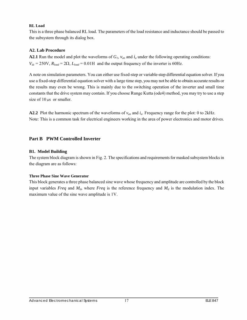
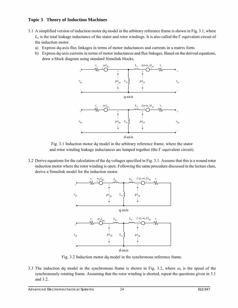
Topic 3 Theory of Induction Machines 3.1 A simplified version of induction motor dq model in the arbitrary reference frame is shown in Fig. 3.1, where
LL is the total leakage inductance of the stator and rotor windings. It is also called the Γ equivalent circuit of the induction motor. a) Express dq-axis flux linkages in terms of motor inductances and currents in a matrix form. b) Express dq-axis currents in terms of motor inductances and flux linkages. Based on the derived equations,
draw a block diagram using standard Simulink blocks.
Lm
(ω-ωr )λdrLL rr
vqr
ωλdsrs
vqs pλqrpλqs
q-axis
Lm
(ω-ωr )λqrLL rr
vdr
ωλqsrs
vds pλdrpλds
d-axis Fig. 3.1 Induction motor dq model in the arbitrary reference frame, where the stator
and rotor winding leakage inductances are lumped together (the Γ equivalent circuit). 3.2 Derive equations for the calculation of the dq voltages specified in Fig. 3.1. Assume that this is a wound rotor
induction motor where the rotor winding is open. Following the same procedure discussed in the lecture class, derive a Simulink model for the induction motor.
Lm
( ωs-ωr )λdr rrωsλdsrs
vqs pλqrpλqs
q-axis
Lm
Llr rrωsλqsrs
vds pλdrpλds
d-axis
( ωs-ωr )λqrLls
LlrLls
Fig. 3.2 Induction motor dq model in the synchronous reference frame.
3.3 The induction dq model in the synchronous frame is shown in Fig. 3.2, where ωs is the speed of the
synchronously rotating frame. Assuming that the rotor winding is shorted, repeat the questions given in 3.1 and 3.2.

Advanced Electromechanical Systems ELE 847 25
3.4 A three phase induction motor is powered by a three phase balanced power supply. The power supply and the
induction motor can be represented by masked subsystems. Assume the induction motor model is in the synchronous reference frame. The output variables of the power supply - induction motor system are stator currents, electromagnetic toque and motor speed in the stator (stationary) reference frame. Draw a system block diagram showing all the subsystem blocks including 3-phase to 2-phase transformation, stationary to rotating transformation and other transformations if required. It is not necessary to show the details of the subsystems.
3.5 Repeat Problem 3.4 except the induction motor model is in the rotor reference frame. Topic 4 Induction Motor Speed Control 4.1 A three-phase induction motor has the following nameplate data: 10hp, 60Hz, 220V and 1150rpm. The
maximum torque (Tmax) of the motor is 155N.m, which occurs at the motor speed of 970rpm. The starting torque of the motor is 70N.m. Assuming that the air gap flux of the motor is kept the constant, sketch to scale the toque versus speed curves at the stator frequency of 60Hz, 40Hz and 20Hz.
4.2 Assuming that the input dc voltage of a three-phase IGBT-based voltage source inverter is 200V and the duty
cycle of the IGBTs is 50% (i.e., the IGBT conduction angle is 180 degrees). a) Determine the amplitude of the fundamental component, 5th, 7th and 11th harmonics of the inverter output
voltage (line-to-line). b) Sketch to scale the line-to-neutral voltage waveform (Phase a) and determine the amplitude of the
fundamental component, 5th, 7th and 11th harmonics. 4.3 Draw the inverter output voltage waveform (line-to-line) assuming that the IGBT devices in Question 4.2 have
a conduction angle of 120 degrees per cycle. Assume that the inverter is loaded with a three-phase balanced resistor. Hint: the IGBT gating signals for the upper and lower IGBTs in the same inverter leg are no longer complementary.
4.4. Derive a Simulink model for a three phase voltage source inverter, assuming the conduction angle of the
switching devices is 180 degrees. 4.5 Draw a block diagram (not Simulink Model) for a three-phase induction motor drive using Volts per Hertz
control scheme. To ensure a constant flux operation, voltage feedback should be used. The voltage drop on the stator winding resistance at low operating frequencies should also be compensated. The drive system is implemented with a sine pulse width modulator.
4.6 Fig. 4.1 shows the block diagram of an induction motor field oriented control scheme. Derive equations and
then Simulink block diagrams for the following subsystems: Is* & θT* Resolver, Current Reference Generator and Flux & Torque Estimator.

Advanced Electromechanical Systems ELE 847 26
Resolver
iT*
if*
PI
Vdc
Flux &Torque
Estimator
Te*
λ∗r
ωmCurrent
ReferenceGeneratorθT
i*sPI
PIθs
DeltaModulator
i*as
VSI
G1
G3
G5
IM
θf
Te
λr
iasibsicsvasvbs
Tachometer
Fig. 4.1 Block diagram of an induction motor field oriented control.
Topic 5 Theory of Synchronous Machines 5.1 Use the synchronous machine model discussed in the lecture class or given in Figure 5.5-1 (Page 202, textbook). Note: Superscripts associated with machine variables may be ignored.
(a) Express flux linkages (λqs, λds, λkq1, λkq2, λkd, and λfd) in terms of machine currents (λqs, λds, λkq1, λkq2, λkd, and λfd).
(b) Derive expressions for the following voltages: Vqs, Vds, Vkq1, Vkq2, Vkd, and Vfd.
5.2 For small size synchronous machines, the damper windings may be omitted to reduce manufacturing cost.
Assuming that for a synchronous machine, the kq2 and kd windings are not equipped, repeat questions given in 5.1.
5.3 State the reasons why the rotor reference frame is often used for synchronous machine analysis. 5.4 Briefly explain the main functions of damper windings. What are the main differences between the
synchronous machine and induction machine.

Advanced Electromechanical Systems ELE 847 27
4. Lecture Slides
Topic 1
Fig. 1-1 Waveforms of a single-phase SCR rectifier.

Advanced Electromechanical Systems ELE 847 28
Lecture Slides – Topic 1
ai
bi
ci
1D 3D 5D
4D 6D 2D
dcv
av
bv
cvLR
2dv
1dv
Fig. 1-2 Waveforms of a three-phase diode rectifier.

Advanced Electromechanical Systems ELE 847 29
Lecture Slides – Topic 1
Fig. 1-3 Simplified Simulink model of three-phase diode rectifier.

Advanced Electromechanical Systems ELE 847 30
Lecture Slides – Topic 1
Fig. 1-4 Typical waveforms of a three-phase SCR rectifier.

Advanced Electromechanical Systems ELE 847 31
Lecture Slides – Topic 1
Fig. 1-5 Simulated waveforms of a three-phase SCR rectifier.
Advanced Electromechanical Systems ELE 847 32
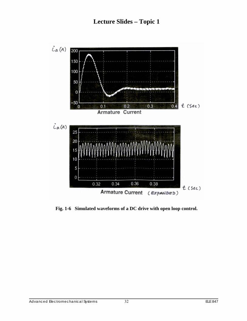
Lecture Slides – Topic 1
Fig. 1-6 Simulated waveforms of a DC drive with open loop control.

Advanced Electromechanical Systems ELE 847 33
Lecture Slides – Topic 1
Fig. 1-7 Simulated waveforms of a DC drive with closed loop control.

Advanced Electromechanical Systems ELE 847 34
Lecture Slides – Topic 3
(Free acceleration)
Fig. 3-1 Simulated waveforms of a three-phase induction motor
in the STATOR (STATIONARY) reference frame.

Advanced Electromechanical Systems ELE 847 35
Lecture Slides – Topic 3
(Free acceleration)
Fig. 3-2 Simulated waveforms of a three-phase induction motor
in the STATOR (STATIONARY) reference frame.

Advanced Electromechanical Systems ELE 847 36
Lecture Slides – Topic 3
(Free acceleration)
Fig. 3-3 Simulated rotor speed waveform of a three-phase induction motor.

Advanced Electromechanical Systems ELE 847 37
Lecture Slides – Topic 3
(Free acceleration)
Fig. 3-4 Simulated waveforms of a three-phase induction motor
in the SYNCHRONOUS reference frame.

Advanced Electromechanical Systems ELE 847 38
Lecture Slides – Topic 3
)pu(asi
)sec(t
)rpm(rn
(a) Simulated waveforms
Stator current asi : 2.56 pu/div; Rotor speed rn : 720rpm/div
Time base: 0.1sec/div (b) Measured waveforms
Fig. 3-5 Simulated and measured waveforms of a three-phase induction motor
during free acceleration.

Advanced Electromechanical Systems ELE 847 39
Lecture Slides – Topic 4
tω
tω
tω
tω
tω
tω
dcV
abv
bvav
cv
tω
tω
bcv
cav
3/ππ π2 π3
I II III IV V VI
3/π
tω
dcV
dcV
dcV
dcV
dcV
1G
2G
3G
4G
5G
6G
5T
6T
5D
6D6G
ai
dcV
1T 3T
4T
1D 3D
4D
1G 3G
4G
a
bc
nbi
ci2T
2D2G
5G
GND
av
Fig. 4-1 Three phase voltage source inverter with square wave operation.

Advanced Electromechanical Systems ELE 847 40
Lecture Slides – Topic 4
abv
bv
av
v mav bmv mcvcrv
crV mV
dcV
dcV
dcV
π π2tω
tω
tω
tω
1abv
)( 1G
)( 3G
baab vvv −=
5T
6T
5D
6D6G
ai
dcV
1T 3T
4T
1D 3D
4D
1G 3G
4G
a
bc
nbi
ci2T
2D2G
5G
GND
av
Fig. 4-2 Principle of sinusoidal pulse width modulation (SPWM).

Advanced Electromechanical Systems ELE 847 41
Lecture Slides – Topic 4
(rpm)rω
rω*rω
(rad)fr
θλ (Wb),
rλfθ
)( Aasi
m)(N ⋅e
T
Fig. 4-3 Simulated waveforms of field oriented control for induction motor drives.

Advanced Electromechanical Systems ELE 847 42
Lecture Slides – Topic 5
Fig. 5-1 Synchronous generator with a salient-pole rotor.

Advanced Electromechanical Systems ELE 847 43
Lecture Slides – Topic 5
Lmq
ωrλdsrs
vqs pλqs
q-axis
iqs
pλkq2
pλkq1
Vkq1
Vkq2
imq
Lls
rkq1
ikq1
ikq2
rkq2
Llkq2
Llkq1
Lmd
ωrλqsrs
vds pλds
d-axis
ids
pλfd
pλkd
Vkd
Vfd
imd
Lls
rkd
ikd
ifdrfd
Llfd
Llkd
Fig. 5-2 dq-axis model of synchronous generator in the rotor reference frame.