Embed Size (px)
Citation preview

1Ultralow-power MEMS-based Radio for WBAN
Cours Highlight© C. Enz 2014
ÉCOLE POLYTECHNIQUE
FÉDÉRALE DE LAUSANNE
Cours Highlight
Ultralow-power MEMS-based Radio for WBAN
Christian Enz1, Aravind Heragu2, David Ruffieux3
1) ICLAB, IMT-STI-EPFL, Switzerland
2) SemTech, Switzerland
3) CSEM, Switzerland
ICLAB
Introduction
High-Q resonators
Co-design of IC with MEMS devices VCO
LNA
PA
MEMS-based radio architectures
Conclusion
Outline
© C. Enz | 2014 Ultralow-power MEMS-based Radio for WBAN Slide 1

2Ultralow-power MEMS-based Radio for WBAN
Cours Highlight© C. Enz 2014
Introduction
ICLAB
WBAN Require ULP Miniaturized Sensor Nodes
Wireless body area networks (WBAN) for health monitoring, connecting wearable devices and as smart user interface
The nodes feature sensing, processing, storing and wireless communication
They are usually battery powered or use remote powering
They require ultralow-power (ULP) and miniaturized wireless sensor nodes
Combination of CMOS system-on-chip (SoC), RF and LF MEMS in a system-in-package (SiP) to achieve a 2.4 GHz, <mW-level, <20 mm3 node
© C. Enz | 2014 Ultralow-power MEMS-based Radio for WBAN Slide 2
battery powered nodes
remote powered nodes
Introduction
ICLAB
2.4GHz
mW‐level
<4x4x1 mm3
WBAN
The WiserBAN EU Project – Conceptual view
© C. Enz | 2014 Ultralow-power MEMS-based Radio for WBAN Slide 3
Hearing aids
Cardiac implants
Cochlear implants
Insulin pumps
RF+IF+LF MEMS
RF & DSP SoC
RADIO IC65nm CMOS
RF & LF MEMS
WiserBANmicrosystem
Heterogenous SiP
Miniatureantenna
EU-FP7-WiserBAN Project at www.wiserban.eu

3Ultralow-power MEMS-based Radio for WBAN
Cours Highlight© C. Enz 2014
Introduction
ICLAB
MEMS-based Circuits for Wireless Connectivity
Use BAW resonator to build RF oscillators and filters
Silicon resonator for frequency reference and real-time-clock (RTC)
Hybrid integration (yield, reduced complexity)
0-level packaging (vacuum sealing & interconnects)
© C. Enz | 2014 Ultralow-power MEMS-based Radio for WBAN Slide 4
EU-FP7-Go4Time Project at www.go4time.eu
MEMSSi Resonator FBAR & ALN
CMOS SoC IC
(Radio, DSP, Memory,...)
Introduction
ICLAB
Simplified MEMS-based Transceiver Architecture
Front-end filters before the LNA Interferers and image rejection, relax linearity requirements, avoid impedance matching network
Front-end filters after the power amplifier (PA) Spurious filtering, avoid impedance matching network
Synthesizer Fixed low phase noise RF LO thanks to high Q
Merged Time & Frequency reference with LF silicon resonator (SiRes)
© C. Enz | 2014 Ultralow-power MEMS-based Radio for WBAN Slide 5
Digital B
aseb
and

4Ultralow-power MEMS-based Radio for WBAN
Cours Highlight© C. Enz 2014
ICLAB
Introduction
High-Q resonators
Co-design of IC with MEMS devices VCO
LNA
PA
MEMS-based radio architectures
Conclusion
Outline
© C. Enz | 2014 Ultralow-power MEMS-based Radio for WBAN Slide 6
High-Q Resonators
ICLAB
High-Q Resonators
On-chip inductors usually have low Q (Q typically smaller than 10 for f0=1GHz)
This affects phase noise (inversely proportional to Q2) and power consumption (inversely proportional to Q)
Resonators with higher Q are hence needed for frequency reference in frequency synthesis
There are different high-Q resonators depending on the frequency range Quartz crystals can be used up to about a few 10 MHz
Surface Acoustic Wave (SAW) resonators can be used from 100 MHz to 1 GHz
Bulk Acoustic Wave (BAW) resonators can be use from 1 GHz to 10 GHz
They all have rather large Q-factor and similar characteristics
© C. Enz | 2014 Ultralow-power MEMS-based Radio for WBAN Slide 7

5Ultralow-power MEMS-based Radio for WBAN
Cours Highlight© C. Enz 2014
High-Q Resonators
ICLAB M.-A. Dubois et al. ISSCC 2005.
Bulk Acoustic Wave (BAW) Devices
AlN piezo layer sandwiched between two electrodes
Thickness around 1 µm allows for f0≈1 to 7 GHz
Acoustic isolation from substrate for high-Q Thin-film Bulk Acoustic Resonator or FBAR (membrane resonators)
Solidly mounted resonator or SMR (resonators with acoustic reflector)
Coupling coefficients up to 7% and Q≈500 to 1000
Frequency trimming by loading top electrode (reduces res. freq.)
© C. Enz | 2014 Ultralow-power MEMS-based Radio for WBAN Slide 8
FBAR
AlN
electrodes
Si wafer
SMR
AlN
Si wafer
electrodes
acoustic
reflector
High-Q Resonators
ICLAB
Si Flexural mode MEMS Resonators
© C. Enz | 2014 Ultralow-power MEMS-based Radio for WBAN Slide 9
Z
X
Y
J. Baborowski, et al., Freq. Control Symp. 2007.
20B_32kHz_380
y = -0.000004x 3 - 0.034592x 2 + 0.071019 x - 0.480839R2 = 0.998416
5
-40-35-30-25-20-15-10
-50
-40 -30 -20 -10 0 10 20 30 40
T (°C) with Tref=25°C
f/f
(ppm
)
Description ValueFlexural mode Out-of-planeStructure Optimized for zero TCF Resonant frequency 25kHz to 30kHzQuality factor 10 MHz
in air 500 to 1000In vacuum 2000 to 3000
Coupling coefficient k2 1.1%Qvac*k2 FoM 20 to 30TCF 0.07 to -2 ppm/°C

6Ultralow-power MEMS-based Radio for WBAN
Cours Highlight© C. Enz 2014
High-Q Resonators
ICLAB
High-Q Resonator Equivalent Circuit
The general equivalent circuit of a high-Q resonator is given by
© C. Enz | 2014 Ultralow-power MEMS-based Radio for WBAN Slide 10
The access resistance Rs and inductance Ls can usually be neglected. Assuming that Qp1, and combining all the capacitances between nodes 1 and 2 into a single capacitance C0, the circuit reduces to the simplified one given below
high-Q resonator Rs Ls
CmRm Lm
RpCp
intrinsic resonator
C10 C20
1 2
C12
1
CmRm Lm
C02 10 20
0 1210 20
pC C
C C CC C
High-Q Resonators
ICLAB
High-Q Resonator Simplified Equivalent Circuit
The simplified equivalent circuit of a high-Q resonator is basically the connection of a motional impedance Zm and a parasitic parallel capacitance C0
Zm is made of a series RmLmCm resonant circuit that corresponds to the mechanical part of the resonator defining the mechanical resonant frequency m and quality factor Qm
The motional inductance Lm is proportional to the mass of the resonator whereas the motional capacitance Cm is proportional to the inverse of its stiffness. The motional resistance Rm represents the mechanical losses
The motional current Im flowing in the motional branch is proportional to the velocity of oscillation
© C. Enz | 2014 Ultralow-power MEMS-based Radio for WBAN Slide 11
1
1
mm m
m mm
m m m m
L C
LQ
R C R

7Ultralow-power MEMS-based Radio for WBAN
Cours Highlight© C. Enz 2014
High-Q Resonators
ICLAB
Resonance and Anti-resonance Frequencies
The imaginary part of the high-Q resonator impedance Zres is equal to zero at the resonance (or series resonance) and anti-resonance (or parallel resonance) frequencies s and p, respectively
Assuming that Qm1, s and p can be approximated by
© C. Enz | 2014 Ultralow-power MEMS-based Radio for WBAN Slide 12
11ands m p r r
m m
K kL C
Where K is defined as0
1andmCK k KC
Typical values: fm 1-10 GHz, K 5-6% , Qm 500-1000, M 25-60
1
1
mm m
m mm
m m m m
L C
LQ
R C R
High-Q Resonators
ICLAB
Coupling Factor
K is linked to the coupling factor which represents the ratio of the stored mechanical energy to the electrical energy and is given by
© C. Enz | 2014 Ultralow-power MEMS-based Radio for WBAN Slide 13
2 22 1
8 1 8since usuallyeff
Kk K K
K
The higher this coupling factor, the larger the tunability of a VCO or the bandwidth of a filter
The product M = K·Qm represents the ratio of the current in the motional and dielectric branch, which should be maximized
This is why M is often used as a factor of merit for piezoelectric resonators
0 0
1mm m
m m
CM K Q Q
C R C

8Ultralow-power MEMS-based Radio for WBAN
Cours Highlight© C. Enz 2014
High-Q Resonators
ICLAB
Mechanical Energy
The motional inductance Lm is proportional to the mass of the resonator whereas the motional capacitance Cm is proportional to the inverse of its stiffness. The motional resistance Rm represents the mechanical losses
The motional current Im flowing in the motional branch is proportional to the velocity of oscillation
The mechanical energy of oscillation is given by
© C. Enz | 2014 Ultralow-power MEMS-based Radio for WBAN Slide 14
2 2 2
22 22
m m m m m m mm m
m mm m
L I I Q R I QE P
C
The mechanical power dissipated in the resonator is given by2 2
22 2
m m mm
m m m
R I IP
Q C
High-Q Resonators
ICLAB
High-Q Resonator Oscillator – Motional Impedance
The high-Q resonator motional impedance is given by
© C. Enz | 2014 Ultralow-power MEMS-based Radio for WBAN Slide 15
1 11
1with and (mistuning)
mm m m m m m
m m m m
m m mm
m m m m m
Z R j L R j R jQj C C
LQ
R C R
In high-Q oscillators, is always close to m (or close to 0) and therefore the pulling p is always much smaller than unity
1m
m mp
Close to the series resonance m, Zm can then be approximated as
2 21 2m m m m m m m
m m m m
p pZ R j R j pQ R jX X
C C with
Hence2
2m
m mp

9Ultralow-power MEMS-based Radio for WBAN
Cours Highlight© C. Enz 2014
High-Q Resonators
ICLAB
Resonator Impedance
© C. Enz | 2014 Ultralow-power MEMS-based Radio for WBAN Slide 16
2
20
11
1
m m mres
m
p p p
jQ
Zj C C
jQ
0
1 1, , , , 1 , m
m m p m p mm m mm m
CQ k Q k Q k K K
R C CL C
2
0 0 0 0
1 1( ) ( )
1andr res m m p res p m
m m m m
M jk MZ Z R Z Z M R
C M j C M C K C
0.95 0.975 1 1.025 1.051
0.5
0
0.5
1
argZres f( )
Zp
2
f
fm m
fx
f p mf f
0.95 0.975 1 1.025 1.051
10
100
1 103
1 104
Zres f( )
Zp
Zr
f
fm m
fx
f
pZ
rZ
p mf f
High-Q Resonators
ICLAB
BAW Resonator 1st-order Model
The resonator impedance Zres is minimum at s
© C. Enz | 2014 Ultralow-power MEMS-based Radio for WBAN Slide 17
2( ) withp res p m mZ Z M R M K Q
Typical values:
fm 1-10 GHz
K 5-6%
Qm 500-1000
M 25-60
The resonator impedance Zres is maximum at p
( )s res s mZ Z R
0.95 0.975 1 1.025 1.051
10
100
1 103
1 104
Zres f( )
Zp
Zr
f
fm m
fx
f
pZ
sZ
p mf f
resZ
with Rm being a few , Zp is in the k range

10Ultralow-power MEMS-based Radio for WBAN
Cours Highlight© C. Enz 2014
High-Q Resonators
ICLAB
Qm 500 K 0.05 zmin 0.042 zmax 25.021 k 1.025
0.95 0.975 1 1.025 1.051
0.5
0
0.5
1
arg zn x( ) 2
x
Qm 500 K 0.05 zmin 0.042 zmax 25.021 k 1.025
0.95 0.975 1 1.025 1.050.01
0.1
1
10
100
zn x( )
zmax
zmin
x
Resonator Normalized Impedance
© C. Enz | 2014 Ultralow-power MEMS-based Radio for WBAN Slide 18
2
0 2
2
11
( ) ( )
1
mn m res
m
xx j
Qz x C C Z x
j x xj
k Q k
2 2min 0 max 02
1 1, ,
1m m r p m p
m
Kx z C C Z z C C Z k M k k M
MM
p mk f fmx f f mx f f
p mk f f
maxz
minz
High-Q Resonators
ICLAB
BAW Impedance
© C. Enz | 2014 Ultralow-power MEMS-based Radio for WBAN Slide 19
Parameters unloaded Units
Coupling coefficient K 5.04 %Intrinsic series resonance 2552 MHz
Parallel resonance f p 2605 MHzIntrinsic series resonance quality factor Q m
487
Parallel cap quality factor at f m Q p
381
Motional inductance L m 104.62 nH
Motional capacitance C m 37.19 fF
Motional resistance R m 3.44 Parallel capacitance C p 872.68 fF
Parallel resistance R p 1.06 Parasitic series resistance R s
1.01

11Ultralow-power MEMS-based Radio for WBAN
Cours Highlight© C. Enz 2014
Parallel-resonance Oscillator
ICLAB
BAW Lattice Filters RF bandwidth limited by K=Cm/C0
Out-of band rejection depends on cell matching
Proper in/out impedances required
Equivalent to LC/CL network in-band
© C. Enz | 2014 Ultralow-power MEMS-based Radio for WBAN Slide 20
2.35 109 2.45 109 2.55 109
104
-100
-50
0
50
100
103
102
101
100
ZS
ZP
ph(ZS)
f [Hz]
2.3 109 2.45 109 2.6 109
-20
-10
0
10
S21
f[Hz]
ICLAB
Introduction
High-Q resonators
Co-design of IC with MEMS devices VCO
LNA
PA
MEMS-based radio architectures
Conclusion
Outline
© C. Enz | 2014 Ultralow-power MEMS-based Radio for WBAN Slide 21

12Ultralow-power MEMS-based Radio for WBAN
Cours Highlight© C. Enz 2014
Parallel-resonance Oscillator
ICLAB
The Cross-coupled Pair for Parallel-resonance Oscillator The classical cross-coupled pair cannot be used with high-Q resonators, since
their dc impedance is extremely high making the cross-coupled pair to latch
The source of the cross-coupled pair has to be decoupled by a capacitor CS to make it stable at dc and show a negative transconductance at the oscillation frequency
© C. Enz | 2014 Ultralow-power MEMS-based Radio for WBAN Slide 22
M2M1
Xtal
CS
Ib Ib
M3 M4
Not appropriate
since it is a latch
Not appropriate
because of mismatches
Stable at dc thanks to
feedback transistors M3-M4
(Ruffieux oscillator) D. Ruffieux, ESSCIRC ’02.
Parallel-resonance Oscillator
ICLAB
Modes of Operation
The Ruffieux oscillator can operate in two modes: Relaxation mode independent of the high-Q resonator
Harmonic mode with a resonance frequency set by the high-Q resonator
Relaxation mode can be avoided by proper sizing of coupling capacitor CS
Some frequency tuning is provided by capacitor CD
Circuit can be analyzed in small-signal to extract the conditions for relaxation oscillation
Then the circuit impedance will be derived allowing to find the conditions for avoiding any relaxation and force harmonic oscillations will be derived from a small-signal analysis
© C. Enz | 2014 Ultralow-power MEMS-based Radio for WBAN Slide 23
M2M1
BAW
CS
Ib Ib
M3 M4
CD
D. Ruffieux, ESSCIRC ’02.

13Ultralow-power MEMS-based Radio for WBAN
Cours Highlight© C. Enz 2014
Parallel-resonance Oscillator
ICLAB
Small-signal Circuit Admittance
Assuming GSGms, the circuit admittance is the given by
© C. Enz | 2014 Ultralow-power MEMS-based Radio for WBAN Slide 24
Finally circuit reduces to
Sm
LL
in
inc
Csn
G
CsG
V
IY
2
1
2
Balanced operation
0L DC C C
Lm
V1
CDGm· V1
V2
Gm· V2
Gms· VS2Gms· VS1
VS2
Rm Cm
C0
CS
GL GL
VS1 GS GS
V1
CDGm· V1
V2
Gm· V2
Gms· VS2Gms· VS1
VS2
C0
CS
GL GL
VS1 GS GS
VinIin
−Gm/2 −CS/n
CL=C0+CD
Vin
GL/2
−GS/2n
Iin
Parallel-resonance Oscillator
ICLAB
Conditions for Relaxation Oscillation
This circuit can oscillate (without the high-Q resonator) because of the negative conductance and susceptance
The oscillation frequency and critical transconductance can be found by setting Yc=0, which can then be solved for 0 and Gmcrit. This leads to
© C. Enz | 2014 Ultralow-power MEMS-based Radio for WBAN Slide 25
1
1
1
2
Lrelaxmcrit
L
S
L
Lrelax
GG
Cn
Cα
C
Gwith
LS CnC or1
Relaxation mode is therefore avoided by choosing
Relaxation can only occur for
LS CnC or1

14Ultralow-power MEMS-based Radio for WBAN
Cours Highlight© C. Enz 2014
Parallel-resonance Oscillator
ICLAB
Harmonic Oscillation
If the losses due to GL are neglected, the circuit impedance is then given by
© C. Enz | 2014 Ultralow-power MEMS-based Radio for WBAN Slide 26
1
21/
1/1
2
22
L
S
S
ms
s
s
LmSLLS
Smc Cn
Cα
C
Gn
s
s
sCsGCCnsCC
sCGnZ andwith
The real and imaginary parts are then given by
22
2
222422
222
22
2
22222
2
1/
1/1
4
4
1/
2
4
2
s
s
LmSLLS
SLmSLc
smmSLLS
mSc
CGCnCCC
CCnGCnCX
GGCnCCC
GCR
For Gm=0 and Gm→∞ we get Rc=0 and
1
1)(
1)0(0
Lmcc
Lmcc C
GXXC
GXX and
Zc(Gm) forms a circle in the complex plane with a radius given by
12 LCradius
Parallel-resonance Oscillator
ICLAB
Im
Re
−Xc
−Rm
A
B
pGm
−Rc
Gm=0
Gm=Gmopt
Gm=Gmmax
Gm→∞
−Xm
2 1LC
2m m
m
pZ R j
C
1
LC
1 1 / 2
1LC
1
1LC
Gm=Gmcrit
Complex Plane Impedance Locus
Two intersections A and B for
It can be shown that, similarly to the basic Pierce oscillator, the only stable point is A
© C. Enz | 2014 Ultralow-power MEMS-based Radio for WBAN Slide 27
12 Lm CR
1For S
L
Cα
n C
S
L
Cα
n C

15Ultralow-power MEMS-based Radio for WBAN
Cours Highlight© C. Enz 2014
Parallel-resonance Oscillator
ICLAB
Oscillation Frequency
If the losses due to GL can be neglected and assuming 0 Gms/(2*CS), capacitance CS can be replaced by a short and the circuit reduces to the parallel circuit on the left, which is equivalent to the series circuit on the right
© C. Enz | 2014 Ultralow-power MEMS-based Radio for WBAN Slide 28
0L DC C C
2 2 22
22
2Re{ }
222
4 1Im{ }
22
for
for
m m mc c
LLm L
mLc c
L Lm L
G G GR Z ω
CCG C
GCX Z ω
C CG C
The complete circuit with the motional branch of the resonator is shown belowAt the resonance frequency, Rm is
compensated by −Rc and the
circuit reduces to
mmm
L
mm
L
mm
eqm
CL
C
C
C
C
CL
1
211
10
Parallel-resonance Oscillator
ICLAB
Oscillation Frequency
For high-Q resonator, Rm is small and the locus of Xm with p lies very close to the imaginary axis. The operation point is therefore close to the intersection of the circle with the imaginary axis corresponding to Gm=0 for which the circuit reactance is given by
© C. Enz | 2014 Ultralow-power MEMS-based Radio for WBAN Slide 29
Lmcc CGXX
1
)0(0
The oscillation frequency can therefore be approximated by solving the following equation for 0
mm
m
LmLmc CCC
p
CXX
0
0
0000
2121
0 0 0
0 0
1 11 1 1
2 2 2 2 2 21 1andm m
D Dm L L m L L
C C C CK K K Kp
C CC C C CC C
1
LC

16Ultralow-power MEMS-based Radio for WBAN
Cours Highlight© C. Enz 2014
Parallel-resonance Oscillator
ICLAB
Critical Transconductance
The critical transconductance is obtained from
© C. Enz | 2014 Ultralow-power MEMS-based Radio for WBAN Slide 30
2 202mcrit
c mL
GR R
C
Which leads to
Which shows that for a given frequency 0 and a given resonator M and C0, the only way to minimize the power consumption is to reduce the load capacitance CD
Assuming the transistors are biased in weak inversion, the power consumption is given by
222 2 0 0 0 00 2
2 22 1
2withL mD
mcrit L m mm m p m c
C C CCG C R M Q K
Q C M C Q p
2 2 withDD b DD T mcrit TkT
P V I V nU G Uq
where >1 is a factor insuring the start-up and maintenance of the oscillations
1 m mm
m m m m
LQ
R C R
Parallel-resonance Oscillator
ICLAB
Frequency Tunability
To implement a VCO, the oscillation frequency can be tuned by changing the capacitance value CD
The ability to tune the frequency is evaluated by deriving the relative variation of the resonance frequency due to a relative change in the load capacitance CD
© C. Enz | 2014 Ultralow-power MEMS-based Radio for WBAN Slide 31
0 0 0
20 0 max0
2 81
D D D
D DD
C C C CK K
C CC C
The tunability is maximum for CD=C0, which also corresponds to a good engineering trade-off for the power consumption
Since 0/0 is proportional to K, tunability is therefore ultimately limited by the K factor, which is usually rather low for high-Q resonators
This limitation has to be accounted for, but can be circumvented by new radio and synthesizer architectures
J. Chabloz, et al., ESSCIRC '07
17Ultralow-power MEMS-based Radio for WBAN
Cours Highlight© C. Enz 2014
Parallel-resonance Oscillator
ICLAB
Oscillation Amplitude and Bias Current
The relation between the actual amplitude and the bias current can be obtained in by calculating the transconductance for the fundamental and equating it to the critical transconductance
Unfortunately no closed form expression can be found, but a numerical evaluation leads to the normalized plot shown below
© C. Enz | 2014 Ultralow-power MEMS-based Radio for WBAN Slide 32
IbGmcrit
A=8limit case:
0
4
8
12
16
20
0 1 2 3 4 5 6 7 8 9 10Normalized bias current Ib/ Icritmin
AnUT
weakinversion
IC0=8 16 32 64
m m L
L S
Q C nC
C C
E. Vittoz, Springer 2010
Parallel-resonance Oscillator
ICLAB
−Gm
V2
2CL
V1Vn
GL
In1In2
Lm
VnL
Rm
−Gm
2CL
GL
Cm
Im+In
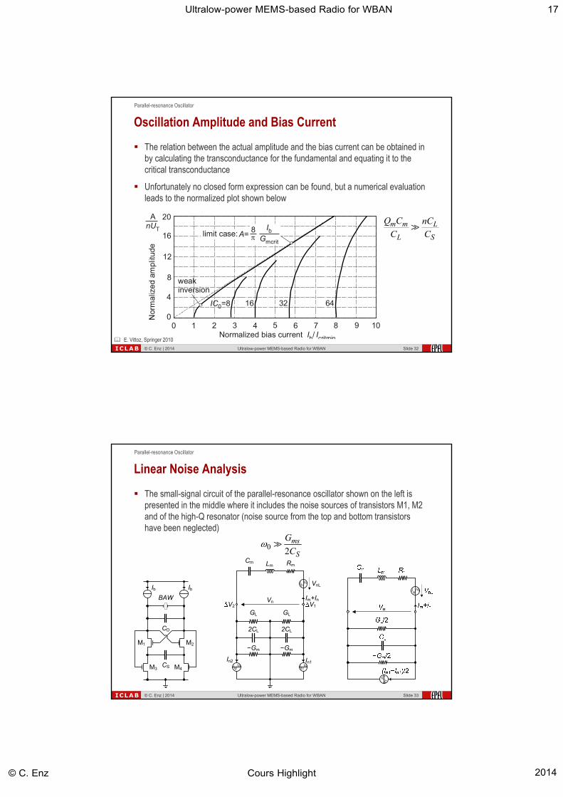
Linear Noise Analysis
The small-signal circuit of the parallel-resonance oscillator shown on the left is presented in the middle where it includes the noise sources of transistors M1, M2 and of the high-Q resonator (noise source from the top and bottom transistors have been neglected)
© C. Enz | 2014 Ultralow-power MEMS-based Radio for WBAN Slide 33
M2M1
BAW
CS
Ib Ib
M3 M4
CD
0 2ms
S
G
C
18Ultralow-power MEMS-based Radio for WBAN
Cours Highlight© C. Enz 2014
Parallel-resonance Oscillator
ICLAB
Vn
Lm
Vnm
Cm
CLVnc
Im+In
Vn
Lm
Vnm
RmCm
−Gm/2
CL
(In1−In2)/2
Im+In
Vn
Lm
Vnm
RmCm
Vnc
Im+In
−RcCL
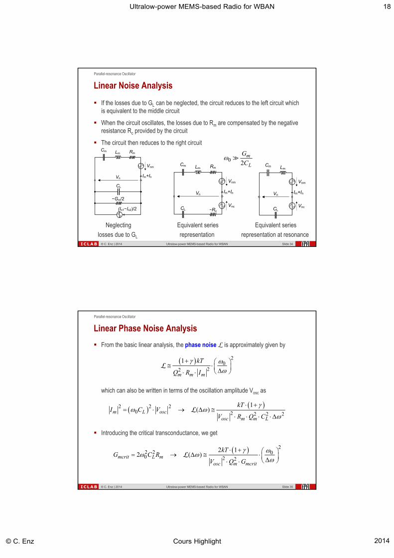
Linear Noise Analysis
If the losses due to GL can be neglected, the circuit reduces to the left circuit which is equivalent to the middle circuit
When the circuit oscillates, the losses due to Rm are compensated by the negative resistance Rc provided by the circuit
The circuit then reduces to the right circuit
© C. Enz | 2014 Ultralow-power MEMS-based Radio for WBAN Slide 34
Neglecting
losses due to GL
Equivalent series
representation
Equivalent series
representation at resonance
0 2m
L
G
C
Parallel-resonance Oscillator
ICLAB
Linear Phase Noise Analysis
From the basic linear analysis, the phase noise L is approximately given by
© C. Enz | 2014 Ultralow-power MEMS-based Radio for WBAN Slide 35
20
22
1
m m m
kT
Q R I
L
22 2 00 2 2
2 12 ( )mcrit L m
osc m mcrit
kTG C R
V Q G
L
which can also be written in terms of the oscillation amplitude Vosc as
2 220 2 2 2 2
1( )m L osc
osc m m L
kTI C V
V R Q C
L
Introducing the critical transconductance, we get

19Ultralow-power MEMS-based Radio for WBAN
Cours Highlight© C. Enz 2014
Parallel-resonance Oscillator
ICLAB
Phase Noise and FoM
Recalling the power consumption in weak inversion
© C. Enz | 2014 Ultralow-power MEMS-based Radio for WBAN Slide 36
2
02
( ) 12 1 T DD
osc oscm
nU VPFoM
kT V VQ
L
2
02
1( ) 2 1 T DD
osc oscm
nU VP kT
V VQ
L
Figure of merit (actually demerit) to minimize can then be defined as
Does not depend on the reactive components, only depends on Qm, Vosc/VDD and on the noise factor (1+)
We find that the product phase noise x power consumption is actually independent of Gmcrit
2 2DD b DD T mcritP V I V nU G
J. Chabloz, et al., ESSCIRC '07
Parallel-resonance Oscillator
ICLAB
BAW and LC Comparison – Phase Noise
Comparing phase noise between LC and BAW oscillator assuming identical 0, Vosc, CL, and T
© C. Enz | 2014 Ultralow-power MEMS-based Radio for WBAN Slide 37
20
20
1 1LC
L LCosc
kT
C QV
L
LC-oscillator BAW oscillator
20
2 2 20
1 m mBAW
L mosc
kT C
C QV
L
The ratio is then given by
01
BAW LC m m LC mm LC L m
LC m L m L
Q C Q CQ Q C C
Q C Q C
since and
LL
The phase noise of the BAW oscillator is therefore much smaller than that of the LC oscillator
Assuming QLC=10, Qm=1000, K=5% and CD=C0 (CL=2C0) leads to
362
LC m LC
m L m
Q C Q KdB
Q C Q

20Ultralow-power MEMS-based Radio for WBAN
Cours Highlight© C. Enz 2014
Parallel-resonance Oscillator
ICLAB
BAW and LC Comparison – Power Dissipation
Comparing critical transconductances between LC and BAW oscillator assuming identical 0, Vosc, CL and assuming transistors are biased in weak inversion
© C. Enz | 2014 Ultralow-power MEMS-based Radio for WBAN Slide 38
LC-oscillator BAW oscillator
2DD b DD T mcritP V I V nU G
202 L
mcrit BAWm m
CG
Q C
02 L
mcrit LCLC
CG
Q
The ratio is then given by
mcrit BAW LC L
mcrit LC m m
G Q C
G Q C
Since Qm>>QLC and CL>>Cm, there is no big difference in power consumption
Assuming QLC=10, Qm=1000, K=5% and CD=C0 (CL=2C0) leads to ≈0.4
Parallel-resonance Oscillator
ICLAB
BAW and LC Comparison – Tuning Range
Comparing tuning range between LC and BAW oscillator assuming identical 0, Vosc, CL
© C. Enz | 2014 Ultralow-power MEMS-based Radio for WBAN Slide 39
LC-oscillator BAW oscillator
0 0
20 0
2 1
D D
DD
C C CK
CC C
0
0 max8
D
D
CK
C
Maximum for CD=C0
0
0
L
L
C
C
Much smaller for the BAW oscillator than for the LC oscillator
Assuming the same CL/CL= CD/CD and K=5% shows that tuning range of the BAW oscillator is about 160 times smaller than that of the LC oscillator

21Ultralow-power MEMS-based Radio for WBAN
Cours Highlight© C. Enz 2014
Parallel-resonance Oscillator
ICLAB
BAW and LC Comparison
© C. Enz | 2014 Ultralow-power MEMS-based Radio for WBAN Slide 40
Ratio Numerical values
Assuming:QLC=10, Qm=1000, K=5%
and CD=C0 (CL=2C0)
Phasenoise
· ≪ 1 36
Power dissipation
· 1 0.4
Frequency tuning 2
·⁄
1 ⁄ 8≪ 1
1160
Parallel-resonance Oscillator
ICLAB
BAW Quadrature VCO at 2.1 GHz
© C. Enz | 2014 Ultralow-power MEMS-based Radio for WBAN Slide 41
> 35 dB
S. Rai, B. Otis, ISSCC 2007.
22Ultralow-power MEMS-based Radio for WBAN
Cours Highlight© C. Enz 2014
ICLAB
Introduction
High-Q resonators
Co-design of IC with MEMS devices VCO
LNA
PA
MEMS-based radio architectures
Conclusion
Outline
© C. Enz | 2014 Ultralow-power MEMS-based Radio for WBAN Slide 42
MEMS-based LNA
ICLAB
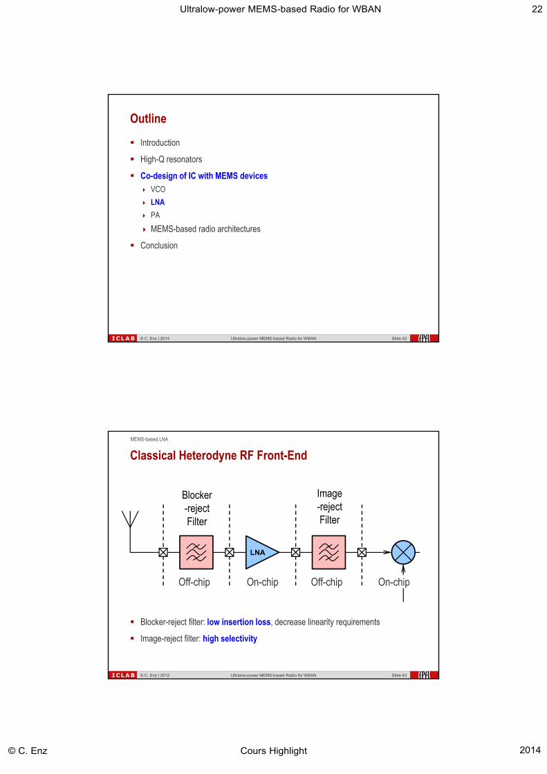
Classical Heterodyne RF Front-End
Blocker-reject filter: low insertion loss, decrease linearity requirements
Image-reject filter: high selectivity
© C. Enz | 2012 Ultralow-power MEMS-based Radio for WBAN Slide 43
LNA
Blocker-rejectFilter
Image-rejectFilter
Off-chip On-chip Off-chip On-chip

23Ultralow-power MEMS-based Radio for WBAN
Cours Highlight© C. Enz 2014
MEMS-based LNA
ICLAB
LNA
High-QBAWFilter
Off-chip On-chip Off-chip On-chip
LNA
High-QBAWFilter
Off-chip On-chip
Front-End with High-Q Filter
High-Q BAW filter can provide both low insertion loss and high selectivity
No need for further image rejection
© C. Enz | 2012 Ultralow-power MEMS-based Radio for WBAN Slide 44
MEMS-based LNA
ICLAB
Filter-LNA interface
BAW resonators require correct termination impedances to work as specified
Impedance matching usually required for correct filter termination
Impedance matching network between BAW filter and LNA can be avoided by using the same BAW resonators within a selective LNA
© C. Enz | 2012 Ultralow-power MEMS-based Radio for WBAN Slide 45
BAWFilter
MatchingNetwork
LNALNA
BAW Filter +
Selective LNA

24Ultralow-power MEMS-based Radio for WBAN
Cours Highlight© C. Enz 2014
MEMS-based LNA
ICLAB
Proposed Selective LNA
Embed lattice filter into the active differential pair taking advantage of the balanced signals
© C. Enz | 2012 Ultralow-power MEMS-based Radio for WBAN Slide 46
J. Chabloz, et al., ISSCC 2006.
Cc CcIq Iq
Z1
Z2
Vin−
Z1
Z2
Vin+
Iout+ Iout−
MEMS-based LNA
ICLAB
LNA Simulated Gain
© C. Enz | 2012 Ultralow-power MEMS-based Radio for WBAN Slide 47
Image Band Signal Band
Frequency [GHz]
Effe
ctiv
e Vo
ltage
Gai
n [d
B]
-80
-60
-40
-20
0
20
2.1 2.2 2.3 2.4 2.5 2.6 2.7 2.8
<30 dB
J. Chabloz, et al., ISSCC 2006.

25Ultralow-power MEMS-based Radio for WBAN
Cours Highlight© C. Enz 2014
MEMS-based LNA
ICLAB
Complete BAW Selective LNA
© C. Enz | 2012 Ultralow-power MEMS-based Radio for WBAN Slide 48
Cc CcIq Iq
Z1
Z2
Z1
Z2
Z1
Z2 Z1
Z2
L1
Vout−
Vout+
Vin−
Vin+
L1
VDD
Lattice prefilter Selective LNA
J. Chabloz, et al., ISSCC 2006.
MEMS-based LNA
ICLAB
LNA Simulated Gain
© C. Enz | 2012 Ultralow-power MEMS-based Radio for WBAN Slide 49
Image Band Signal Band
Frequency [GHz]
Effe
ctiv
e Vo
ltage
Gai
n [d
B]
-80
-60
-40
-20
0
20
2.1 2.2 2.3 2.4 2.5 2.6 2.7 2.8
> 50 dB
J. Chabloz, et al., ISSCC 2006.

26Ultralow-power MEMS-based Radio for WBAN
Cours Highlight© C. Enz 2014
MEMS-based LNA
ICLAB
Layout Implementation and Chip Photograph
© C. Enz | 2012 Ultralow-power MEMS-based Radio for WBAN Slide 50
J. Chabloz, et al., ISSCC 2006.
MEMS-based LNA
ICLAB
Measured RF Front-End Gain
© C. Enz | 2012 Ultralow-power MEMS-based Radio for WBAN Slide 51
-50
-40
-30
-20
-10
0
10
20
2200 2300 2400 2500 2600 2700
RF Frequency [MHz]
Volta
ge G
ain
[dB
]
Simulated
Simulated w extracted BAWsand losses
Measured
50 dB
J. Chabloz, et al., ISSCC 2006.

27Ultralow-power MEMS-based Radio for WBAN
Cours Highlight© C. Enz 2014
MEMS-based LNA
ICLAB
Measurements Summary
© C. Enz | 2012 Ultralow-power MEMS-based Radio for WBAN Slide 52
Parameter Units
Supply voltage 1.2 VCurrent consumption 1.5 mAPower consumption 1.8 mW
Voltage gain 12 dBImage rejection > 50 dBRF bandwidth 100 MHz
Noise figure 11 dBInput 1dB compression -26 dBm
Input IP3 -16.1 dBm
SFDR (BW=300kHz, SNR=0dB) 92 dB
fRF = 2.5GHz, fLO = 2.41GHz
J. Chabloz, et al., ISSCC 2006.
MEMS-based LNA
ICLAB
-50
-40
-30
-20
-10
0
10
20
2200 2300 2400 2500 2600 2700RF Frequency [MHz]
Volta
ge G
ain
[dB
]
BAW based LNA
© C. Enz | 2014 Ultralow-power MEMS-based Radio for WBAN Slide 53
Simulated w extracted BAWsand losses
Measured
Cc CcIq Iq
Z1
Z2
Z1
Z2
Z1
Z2 Z1
Z2
L1
Vout−
Vout+
Vin−
Vin+
L1
VDD
Lattice prefilter Selective LNA
J. Chabloz, et al., ISSCC 2006.

28Ultralow-power MEMS-based Radio for WBAN
Cours Highlight© C. Enz 2014
ICLAB
Introduction
High-Q resonators
Co-design of IC with MEMS devices VCO
LNA
PA
MEMS-based radio architectures
Conclusion
Outline
© C. Enz | 2014 Ultralow-power MEMS-based Radio for WBAN Slide 54
MEMS-based PA
ICLAB
Transmitter: Class-E Power Amplifier Principle
© C. Enz | 2012 Ultralow-power MEMS-based Radio for WBAN Slide 55
M. Contaldo, et al., ECCTD 2009.

29Ultralow-power MEMS-based Radio for WBAN
Cours Highlight© C. Enz 2014
MEMS-based PA
ICLAB
Class-E BAW PA Equivalence
Take advantage of balanced nature of signals in differential structure and combine with lattice filter
© C. Enz | 2012 Ultralow-power MEMS-based Radio for WBAN Slide 56
Mason’s equivalence allows to combine the parallel branches of the BAW resonators and include them in the shunt capacitor Csh
The motional branch can then be used for the series branch of the class-E PA
1 1m pY Y Y
Loaded shunt device Unloaded series device
2 2m pY Y Y
MEMS-based PA
ICLAB
PPA & PA Implementation with BAW Filter Stage
© C. Enz | 2012 Ultralow-power MEMS-based Radio for WBAN Slide 57
M. Contaldo, et al., ISSCC 2010.
30Ultralow-power MEMS-based Radio for WBAN
Cours Highlight© C. Enz 2014
MEMS-based PA
ICLAB
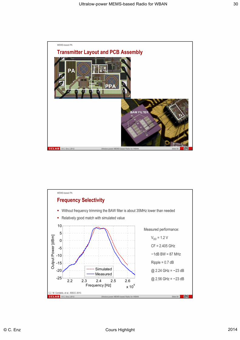
Transmitter Layout and PCB Assembly
© C. Enz | 2012 Ultralow-power MEMS-based Radio for WBAN Slide 58
MEMS-based PA
ICLAB
Frequency Selectivity
Without frequency trimming the BAW filter is about 35MHz lower than needed
Relatively good match with simulated value
© C. Enz | 2012 Ultralow-power MEMS-based Radio for WBAN Slide 59
Measured performance:
VDD = 1.2 V
CF = 2.405 GHz
−1dB BW = 87 MHz
Ripple = 0.7 dB
@ 2.24 GHz = −23 dB
@ 2.56 GHz = −23 dB2.2 2.3 2.4 2.5 2.6
x 109
-25
-20
-15
-10
-5
0
5
10
Frequency [Hz]
Ou
tpu
t Po
we
r [d
Bm
]
SimulatedMeasured
M. Contaldo, et al., ISSCC 2010.

31Ultralow-power MEMS-based Radio for WBAN
Cours Highlight© C. Enz 2014
MEMS-based PA
ICLAB
Output Power Control
By sweeping discretely the bias of the power stage
All curves include the BAW filter losses
© C. Enz | 2012 Ultralow-power MEMS-based Radio for WBAN Slide 60
Measured performance:
VDD = 1.2 V
Pout = −6 dBm to 8.4 dBm
max ηd = 24.2%
max ηov = 21%
0 5 10 15-10
-5
0
5
10
15
20
25
Input DC bias PA step
Effi
cie
ncy
[%] a
nd
Ou
tpu
t Po
we
r [d
Bm
]
Drain efficiencyOver. efficiencyOutput power
M. Contaldo, et al., ISSCC 2010.
MEMS-based PA
ICLAB
Transmitter Layout
0.18µm CMOS technology
1.25 x 1.5 mm2
Integrated in a complete BAW-based transceiver
No external components in the Tx other than the BAW filter and the BALUN for test purposes
© C. Enz | 2012 Ultralow-power MEMS-based Radio for WBAN Slide 61

32Ultralow-power MEMS-based Radio for WBAN
Cours Highlight© C. Enz 2014
MEMS-based PA
ICLAB
Measurements Test-bench
© C. Enz | 2012 Ultralow-power MEMS-based Radio for WBAN Slide 62
MEMS-based PA
ICLAB
Unmodulated RF Signal
fBAW = 2.339 GHz
fIF= fBAW/32 = 73 MHz
fLC = 28/32 fBAW = 2.046 GHz
fRF = 2.412 GHz
PN, Integer Mode
© C. Enz | 2012 Ultralow-power MEMS-based Radio for WBAN Slide 63
102
103
104
105
106
107
-160
-140
-120
-100
-80
-60
-40
-20
Offset frequency [Hz]
Ph
ae
no
ise
[dB
c/H
z]
L = −136.6 dBc/Hz at 1 MHz offset

33Ultralow-power MEMS-based Radio for WBAN
Cours Highlight© C. Enz 2014
MEMS-based PA
ICLAB
Broadband Spectrum
Curve normalized to
Pout = 5.4 dBm
fBAW = 2.339 GHz
fIF = 73 MHz
Spurs attenuations
IF 2nd h. @ -48 dBc
-1, +3, -5 h. < -63 dBc
-3, +5, -7 h. < -50 dBc
DCO feedth.: -61 dBc
© C. Enz | 2012 Ultralow-power MEMS-based Radio for WBAN Slide 64
-5 -4 -3 -2 -1 0 1 2 3 4 5-80
-70
-60
-50
-40
-30
-20
-10
0
fBAW
+ n fIF
dB
c
MEMS-based PA
ICLAB
Modulated Spectra
1 Mb/s GFSK
BT modulation
-21.7 dBc, -21.4 dBc@ ±500 kHz
ACP 2: -42 dBm
ACP 3: -49 dBm
BT LE modulation
ACP 2: -41 dBm
ACP 3: -44 dBm
© C. Enz | 2012 Ultralow-power MEMS-based Radio for WBAN Slide 65
-4 -3 -2 -1 0 1 2 3 4 -80
-70
-60
-50
-40
-30
-20
-10
0
Frequency offset [MHz]
dB
c
BT mask
BT mi=0.34BT LE

34Ultralow-power MEMS-based Radio for WBAN
Cours Highlight© C. Enz 2014
MEMS-based PA
ICLAB
Power Consumption Breakdown
© C. Enz | 2012 Ultralow-power MEMS-based Radio for WBAN Slide 66
Block Cons. [mW]
Synthesis 11.11
BAW DCO 2.37
Dividers, ΣΔ 3.28
LC VCO 3.38
PLL div., PFD, CP 2.08
Selective TX 36.19
IF buffer 0.56
RC/CR 2.34
SSB mixer 3.68
PPA 3.82
PA 25.79
Chip in TX mode 47.3
55%
8%
8%
6%
23%
At Pout = 5.4 dBm
PA PPA
SSB mix RC/CR, Buf IF
Synthesis
MEMS-based PA
ICLAB
BAW based PA
© C. Enz | 2014 Ultralow-power MEMS-based Radio for WBAN Slide 67
2.2 2.3 2.4 2.5 2.6
x 109
-25
-20
-15
-10
-5
0
5
10
Frequency [Hz]
Ou
tpu
t Po
we
r [d
Bm
]
SimulatedMeasured
M. Contaldo, et al., ISSCC 2010.

35Ultralow-power MEMS-based Radio for WBAN
Cours Highlight© C. Enz 2014
ICLAB
Introduction
High-Q resonators
Co-design of IC with MEMS devices VCO
LNA
PA
MEMS-based radio architectures
Conclusion
Outline
© C. Enz | 2014 Ultralow-power MEMS-based Radio for WBAN Slide 68
MEMS-based Receiver Architectures
ICLAB
N
BAW DCO
PLLAD
PLLLF
SiResRTC M
ADC
DIG
ITAL BASEBAND
LNA
PA
BAW
2.32GHz 80-160MHz
RX DATA
CHANNEL
SELECT
TX DATA
PROG SYS
CLOCK
2.4GHz
Wide-IF to Compensate BAW LO Lack of Tuning
IF signal obtained from BAW LO with fractional-N divider Quantization noise issue !
Quadrature needed for I & Q or SSB mixing
Wide bandwidth PLL for single point quasi direct modulation at up to Mbps No 20log(N) noise scaling, higher fREF
© C. Enz | 2014 Ultralow-power MEMS-based Radio for WBAN Slide 69
D.Ruffieux et al., JSSC, Jan. 2009, ESSCIRC 2010.

36Ultralow-power MEMS-based Radio for WBAN
Cours Highlight© C. Enz 2014
MEMS-based Receiver Architectures
ICLAB
PLL-free Super-high IF Rx Architecture with BAW Filter
Channel selection directly done at RF (super-high-IF) by the proposed low powerBAW pseudo-lattice based Amplifier-Mixer-Filter (AMF) cell.
Quadrature down-conversion to baseband by sub-sampling.
BAW pseudo-lattice also provides bandpass anti-aliasing filtering
All clocks required for channel selection, down-conversion, ADC - generated byinteger division of the BAW DCO signal.
© C. Enz | 2014 Ultralow-power MEMS-based Radio for WBAN Slide 70
A. Heragu et al., ESSCIRC 2012, A. Heragu et al., RFIC 2012.
MEMS-based Receiver Architectures
ICLAB
Measurements
Integrated in 0.18-µm CMOS process.
BAW resonators wire bonded to the chip.
© C. Enz | 2014 Ultralow-power MEMS-based Radio for WBAN Slide 71
Block Current (mA)
LNA 1.5
BAW DCO 1.21
AMF cell 1.08
IF amplifier 4x 0.1
Dividers, buffers, ADC, demodulator
1.75
Total 5.94
Power supply VDD = 1.8 V

37Ultralow-power MEMS-based Radio for WBAN
Cours Highlight© C. Enz 2014
ICLAB
Introduction
High-Q resonators
Co-design of IC with MEMS devices VCO
LNA
PA
MEMS-based radio architectures
Conclusion
Outline
© C. Enz | 2014 Ultralow-power MEMS-based Radio for WBAN Slide 72
ICLAB
WBAN require ULP and miniaturized nodes that feature sensing, processing, storage and wireless connectivity
Such nodes can be designed taking advantage of MEMS resonators to build an ULP MEMS-based radio
BAW resonators can be used in: the LNA to provide selectivity, relax linearity requirements and avoid any impedance
matching
a class-E PA for adding selectivity and avoid impedance matching while achieving good power efficiency
RF oscillator to significantly improve the phase noise
High-Q silicon resonators can be used in the frequency synthesis replacing the quartz crystal for reference frequency and RTC
The use of these MEMS devices requires new and optimized radio architecturesand dedicated circuits
A 2.4 GHz radio for ULP Bluetooth link has been demonstrated
Conclusion
© C. Enz | 2014 Ultralow-power MEMS-based Radio for WBAN Slide 73

38Ultralow-power MEMS-based Radio for WBAN
Cours Highlight© C. Enz 2014
ICLAB
© C. Enz |
2014Ultralow-power MEMS-based Radio for WBAN
Slide
74Ultra-low Power 2.4 GHz MEMS-based Radio (RFIC 2012)
Thank You for your Attention !