Embed Size (px)
Citation preview
Copper Apparatus
www.AFLtele.com • 1.800.235.3423
Transition Cable
Repeater Cases
Demarcation Products
1
Table of Contents
Demarcation
CG-500 Coax Demarcation Enclosure . . . . . . . . . . . . . . . . . . . . . . . .3
CG-1000 Coax Demarcation Enclosure . . . . . . . . . . . . . . . . . . . . . . .4
CG-1500 Coax Demarcation Enclosure . . . . . . . . . . . . . . . . . . . . . . .5
CG-2000 Coax Demarcation Enclosure . . . . . . . . . . . . . . . . . . . . . . .6
OPE-92000 Coax Demarcation Enclosure . . . . . . . . . . . . . . . . . . . . .7
SNI-760 Network Interface Device . . . . . . . . . . . . . . . . . . . . . . . . . .8
SNI-730 Network Interface Device . . . . . . . . . . . . . . . . . . . . . . . . .10
SNI-4600 Network Interface Device . . . . . . . . . . . . . . . . . . . . . . . .12
SNI-4300 Network Interface Device . . . . . . . . . . . . . . . . . . . . . . . .14
SNI-1100 Network Interface Device . . . . . . . . . . . . . . . . . . . . . . . . .16
ML-6 Indoor Network Interface Device . . . . . . . . . . . . . . . . . . . . . . .18
Line Modules for Network Interface Devices . . . . . . . . . . . . . . . . . . .20
SNI-8925 Multiline Network Interface Device . . . . . . . . . . . . . . . . . .22
SNI-2125 25-Line Network Interface Device . . . . . . . . . . . . . . . . . .24
1642 Termination Enclosure . . . . . . . . . . . . . . . . . . . . . . . . . . . . . .25
1642XL Termination Enclosure . . . . . . . . . . . . . . . . . . . . . . . . . . . .26
1642 IDC Termination Enclosure . . . . . . . . . . . . . . . . . . . . . . . . . . .27
TA-200 Series Demarcation Enclosures . . . . . . . . . . . . . . . . . . . . . .28
LPF-200 Series - ADSL POTS Splitters . . . . . . . . . . . . . . . . . . . . . .29
Radio Frequency Interference Filter (RFI) . . . . . . . . . . . . . . . . . . . . .31
Half Ringer Equivalent Circuit . . . . . . . . . . . . . . . . . . . . . . . . . . . . .32
3Q06

2

3
The Keptel® CG-500 Coax Demarcation Enclosure provides a secure compartment for terminating coax, and mounting any combination of splitters and/or a ground blocks . Constructed of a weather-resistant/high impact thermoplastic alloy, the hinged cover design allows easy access while the self-sealing individual entrance ports prevent water and insects from entering . The organized mounting arrangements not only create a stan-dardized method for high quality drop installations, but also allow future expandability for broadband equipment .
Keptel® CG-500Coax Demarcation Enclosure
Ordering Information
MODEL # PART #
CG-500 92114-00-01
Specifications
PARAMETER VALUES
Dielectric Strength Minimum 2500 Vrms for 1 minute
Torque (mounting bosses) 20 in ./lbs .
High Temperature Storage/Mold Stress °F (°C) 14 days at 159 (70 .55)
Temperature Cycling with Humidity °F (°C) 150 day cycling from 40-140 (4 .44-60) with 95% RH
Impact Test °F (°C) -40 (-40), 5 ft ./lbs . on all external surfaces
Drop Test °F (°C) -40 (-40), 5 ft . (152 .4 cm) onto concrete surface 4 times
Rain 24 hours at 10 psi
UV Resistance (Days Exposed) 60 per ASTM-G26-84
Salt Fog (Days Exposed) 60 per ASTM-BLL7-90
Flammability UL94-5V
Chemical Resistance 30 Days at 100°F and 95% RHResists chipping and/or cracking when subject to: house paint, wasp spray, sulfuric acid, kerosene and sodium hydroxide
Material UL® listed flame retardant thermoplastic alloy
Dimensions (H x W x D) in . (cm) 6 .3 x 7 .8 x 2 .0 (15 .70 x 19 .70 x 5 .00)
Cable Entrances in . (cm) diameter - Output 3 x 0 .875 (2 .1) knockouts
Cable Entrances in . (cm) diameter - Input 3 x 0 .875 (2 .1) knockouts
Covers Standard - molded-in snap finger and “F” termination
Features
• Weather-resistant/high impact thermo-plastic alloy
• Self-latching, hinged cover design allows easy access without loose parts
• Organized internal mounting bosses create a standardized mounting arrangement
• Custom logo area• Snap close cover with padlock and
F-terminator; other lock options also available
• Conduit ready knock-outs• Self-sealing individual entrance ports
prevent water and insects from entering the NID
© 2002, AFL Telecommunications, all rights reserved . Revision 0, 4 .01 .05 Specifications are subject to change without notice .
4
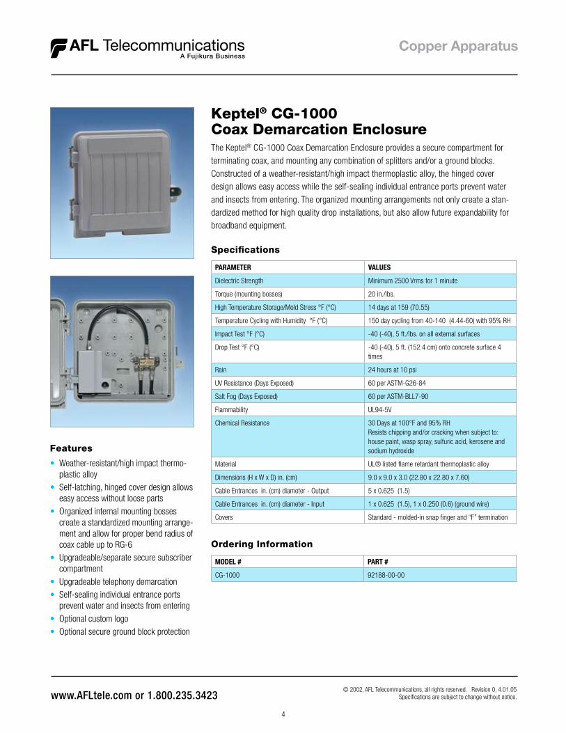
The Keptel® CG-1000 Coax Demarcation Enclosure provides a secure compartment for terminating coax, and mounting any combination of splitters and/or a ground blocks . Constructed of a weather-resistant/high impact thermoplastic alloy, the hinged cover design allows easy access while the self-sealing individual entrance ports prevent water and insects from entering . The organized mounting arrangements not only create a stan-dardized method for high quality drop installations, but also allow future expandability for broadband equipment .
Keptel® CG-1000Coax Demarcation Enclosure
Ordering Information
MODEL # PART #
CG-1000 92188-00-00
Specifications
PARAMETER VALUES
Dielectric Strength Minimum 2500 Vrms for 1 minute
Torque (mounting bosses) 20 in ./lbs .
High Temperature Storage/Mold Stress °F (°C) 14 days at 159 (70 .55)
Temperature Cycling with Humidity °F (°C) 150 day cycling from 40-140 (4 .44-60) with 95% RH
Impact Test °F (°C) -40 (-40), 5 ft ./lbs . on all external surfaces
Drop Test °F (°C) -40 (-40), 5 ft . (152 .4 cm) onto concrete surface 4 times
Rain 24 hours at 10 psi
UV Resistance (Days Exposed) 60 per ASTM-G26-84
Salt Fog (Days Exposed) 60 per ASTM-BLL7-90
Flammability UL94-5V
Chemical Resistance 30 Days at 100°F and 95% RHResists chipping and/or cracking when subject to: house paint, wasp spray, sulfuric acid, kerosene and sodium hydroxide
Material UL® listed flame retardant thermoplastic alloy
Dimensions (H x W x D) in . (cm) 9 .0 x 9 .0 x 3 .0 (22 .80 x 22 .80 x 7 .60)
Cable Entrances in . (cm) diameter - Output 5 x 0 .625 (1 .5)
Cable Entrances in . (cm) diameter - Input 1 x 0 .625 (1 .5), 1 x 0 .250 (0 .6) (ground wire)
Covers Standard - molded-in snap finger and “F” termination
Features
• Weather-resistant/high impact thermo-plastic alloy
• Self-latching, hinged cover design allows easy access without loose parts
• Organized internal mounting bosses create a standardized mounting arrange-ment and allow for proper bend radius of coax cable up to RG-6
• Upgradeable/separate secure subscriber compartment
• Upgradeable telephony demarcation• Self-sealing individual entrance ports
prevent water and insects from entering• Optional custom logo• Optional secure ground block protection
© 2002, AFL Telecommunications, all rights reserved . Revision 0, 4 .01 .05 Specifications are subject to change without notice .

5
The Keptel® CG-1500 Coax Demarcation Enclosure provides a secure compartment for terminating coax, and mounting any combination of splitters and/or a ground blocks . Constructed of a weather-resistant/high impact thermoplastic alloy, the hinged cover design allows easy access while the self-sealing individual entrance ports prevent water and insects from entering . The organized mounting arrangements not only create a standardized method for high quality drop installations, but also allow future expandability for broadband equipment .
Keptel® CG-1500Coax Demarcation Enclosure
Ordering Information
MODEL # PART #
CG-1500 912440-00-00
Specifications
PARAMETER VALUES
Dielectric Strength Minimum 2500 Vrms for 1 minute
Torque (mounting bosses) 20 in ./lbs .
High Temperature Storage/Mold Stress °F (°C) 14 days at 159 (70 .55)
Temperature Cycling with Humidity °F (°C) 150 day cycling from 40-140 (4 .44-60) with 95% RH
Impact Test °F (°C) -40 (-40), 5 ft ./lbs . on all external surfaces
Drop Test °F (°C) -40 (-40), 5 ft . (152 .4 cm) onto concrete surface 4 times
Rain 24 hours at 10 psi
UV Resistance (Days Exposed) 60 per ASTM-G26-84
Salt Fog (Days Exposed) 60 per ASTM-BLL7-90
Flammability UL94-5V
Chemical Resistance 30 Days at 100°F and 95% RHResists chipping and/or cracking when subject to: house paint, wasp spray, sulfuric acid, kerosene and sodium hydroxide
Material U .L .® listed flame retardant thermoplastic alloy
Dimensions (H x W x D) in . (cm) 12 .25 x 12 x 5 .25 (31 .10 x 30 .50 x 13 .30)
Cable Entrances in . (cm) diameter - Output 5 x 0 .625 (1 .5)
Cable Entrances in . (cm) diameter - Input 2 x 0 .750 (1 .9), 1 x 0 .650 (0 .6) (ground wire)
Covers Standard - molded-in snap finger and “F” termination
Features
• Weather-resistant/high impact thermo-plastic alloy
• Self-latching, hinged cover design allows easy access without loose parts
• Organized internal mounting bosses create a standardized mounting arrange-ment and allow for proper bend radius of coax cable up to RG-6
• Upgradeable telephony demarcation• Self-sealing individual entrance ports
prevent water and insects from entering the NID
• Optional custom logo• Optional secure ground block protection • 2 prewire knockouts
© 2002, AFL Telecommunications, all rights reserved . Revision 0, 4 .01 .05 Specifications are subject to change without notice .

6
The Keptel® CG-2000 Coax Demarcation Enclosure provides a secure compartment for terminating coax, and mounting any combination of splitters and/or ground blocks . Constructed of a weather-resistant/high impact thermoplastic alloy, the hinged cover design allows easy access while the self-sealing individual entrance ports prevent water and insects from entering . The organized mounting arrangements not only create a standardized method for high quality drop installations, but also allow future expandability for broadband equipment .
Keptel® CG-2000 Coax Demarcation Enclosure
Ordering Information
MODEL # PART #
CG-2000 with Hexhead Cover Fastener 92393-00-00
CG-2000 with cover snap closure only 92069-00-01
Specifications
PARAMETER VALUES
Dielectric Strength Minimum 2500 Vrms for 1 minute
Torque (mounting bosses) 20 in ./lbs .
High Temperature Storage/Mold Stress °F (°C) 14 days at 159 (70 .55)
Temperature Cycling with Humidity °F (°C) 150 day cycling from 40-140 (4 .44-60) with 95% RH
Impact Test °F (°C) -40 (-40), 5 ft ./lbs . on all external surfaces
Drop Test °F (°C) -40 (-40), 5 ft . (152 .4 cm) onto concrete surface 4 times
Rain 24 hours at 10 psi
UV Resistance (Days Exposed) 60 per ASTM-G26-84
Salt Fog (Days Exposed) 60 per ASTM-BLL7-90
Flammability UL94-5V
Chemical Resistance 30 Days at 100°F and 95% RHResists chipping and/or cracking when subject to: house paint, wasp spray, sulfuric acid, kerosene and sodium hydroxide
Material UL® listed flame retardant thermoplastic alloy
Dimensions (H x W x D) in . (cm) 13 .0 x 9 .0 x 3 .0 (33 .00 x 22 .80 x 7 .60)
Cable Entrances in . (cm) diameter - Output 8 x 0 .500 (1 .2)
Cable Entrances in . (cm) diameter - Input 2 x 0 .625 (1 .5), 1 x 0 .250 (0 .6) (ground wire)
Covers 3/8" hex screw or pin-in-hex security fastener
Features
• Self-sealing individual entrance ports• Internal mounting bosses create a
standardized mounting arrangement• Optional custom logo
• Self-latching, hinged cover design allows easy access without loose parts
• Vertical splitter mounting plate available• Weather-resistant/high impact thermo-
plastic alloy
© 2002, AFL Telecommunications, all rights reserved . Revision 0, 4 .01 .05 Specifications are subject to change without notice .

7
The Keptel® OPE-92000 Coax Demarcation Enclosure provides a secure compartment for terminating coax, and mounting any combination of splitters and/or a ground blocks . Constructed of a weather-resistant/high impact thermoplastic alloy, the hinged cover design allows easy access while the self-sealing individual entrance ports prevent water and insects from entering . The organized mounting arrangements not only create a standardized method for high quality drop installations, but also allow future expandability for broadband equipment .
Keptel® OPE-92000Coax Demarcation Enclosure
Ordering Information
MODEL # PART #
OPE-92000 92000
Specifications
PARAMETER VALUES
Dielectric Strength Minimum 2500 Vrms for 1 minute
Torque (mounting bosses) 20 in ./lbs .
High Temperature Storage/Mold Stress °F (°C) 14 days at 159 (70 .55)
Temperature Cycling with Humidity °F (°C) 150 day cycling from 40-140 (4 .44-60) with 95% RH
Impact Test °F (°C) -40 (-40), 5 ft ./lbs . on all external surfaces
Drop Test °F (°C) -40 (-40), 5 ft . (152 .4 cm) onto concrete surface 4 times
Rain 24 hours at 10 psi
UV Resistance (Days Exposed) 60 per ASTM-G26-84
Salt Fog (Days Exposed) 60 per ASTM-BLL7-90
Flammability UL94-5V
Chemical Resistance 30 Days at 100°F and 95% RHResists chipping and/or cracking when subject to: house paint, wasp spray, sulfuric acid, kerosene and sodium hydroxide
Material UL® listed flame retardant thermoplastic alloy
Dimensions (H x W x D) in . (cm) 15 .5 x 11 .3 x 3 .8 (39 .30 x 28 .50 x 9 .50)
Cable Entrances in . (cm) diameter - Output 5 x 0 .625 (1 .5)
Cable Entrances in . (cm) diameter - Input 1 x 0 .625 (1 .5), 1 x 0 .250 (0 .6) (ground wire)
Covers molded-in snap finger and locking loop
Features
• Isolated customer access compartment enables the customer to run extensions while preventing access to the broad-band provider compartment
• Weather-resistant/high impact thermo-plastic alloy
• Self-latching, hinged cover design allows easy access without loose parts
• Organized internal mounting bosses create a standardized mounting arrangement and allow for proper bend radius of coax cable up to RG-6
• Self-sealing individual entrance ports prevent water and insects from entering the NID
© 2002, AFL Telecommunications, all rights reserved . Revision 0, 4 .01 .05 Specifications are subject to change without notice .

8
The Keptel® SNI®-760 is designed to meet requirements for one to six line outdoor residential NIDs . This unit can be equipped with six individual line modules and six station protectors .
Keptel® SNI®-760 Network Interface Device
Features
• Compatible with Corning Cable Systems (Siecor) CAC®-7600• Field upgradeable individual line modules• Optional individual subscriber security covers• Remote testing electronics and RFI filters• Rugged, weatherproof thermoplastic alloy housing• Grommeted entrances• Designed and tested to Telcordia™ GR-49-CORE• UL® Listed
Specifications
PARAMETER VALUE
Insulation Resistance Minimum of 100 Megohms @ ± 200 V dc
Series Resistance 100 milliohms maximum with jacks mated
Dielectric Withstand 1000 Vrms for 1 minute
Dielectric Withstand to Mounting Surfaces Minimum 2500 Vrms
High Current Capacity 5 amp current for 15 minutes
Wire Installation Spacings 1" for drop wire, 1⁄4" for inside wire
Wiring Network wire-24 AWG solid, plug cable wire-26 AWG stranded
Torque 20 in ./lbs .
High Temperature Storage/Mold Stress °F (°C) 14 days at 159 (70 .55)
Temperature Cycling °F (°C) 30 day cycling from -40 to +140 (-40 to 60)
Temperature Cycling with Humidity °F (°C) 30 day cycling from +40 to +140 (4 .44 to 60) with 95% RH
Impact Test °F (°C) -40 (-40)
Drop Test °F (°C) -40 (-40)
Rain UL® 1863 for 24 hours at 10 psi
Salt Fog (Days Exposed) 30
Sunshine (Days Exposed) 60
Fungus Resistance ASTM G-21 rating of 0
Flammability Oxygen index of 28%, UL746C 5 inch flame test
Chemical Resistance 30 Days at 100 °F and 95% RH, subject to: CRC226 water displacement lubricant, WD40 water displace-ment lubricant, 4353 ant and wasp spray, 3% H
2SO
4, 0 .2N
NaOH, Kerosene, 10% Igepal CO-630
Dimensions (H x W x D) in . (cm) 10 .00 x 8 .37 x 3 .00 (25 .40 x 21 .92 x 7 .62)
© 2002-2007, AFL Telecommunications, all rights reserved . Revision 1, 8 .10 .07 Specifications are subject to change without notice .

9
Keptel® SNI®-760 Network Interface Device
EXAMPLE: SNI®-760 – 1 – B – 2 – 3 – 37 – H – CLM-5C-1
This model number indicates that the following has been ordered:SNI®-760 housing, supplied without individual subscriber security covers, line module includes; 4 screws, 2 wire RJ-11 interface, Half Ringer equivalence, three line capacity, Bourns 125EW lightning protection, 3/8" Hex Head screw for telco cover fastener, and an optional single line coax demarcation module .
SNI®-760
SNI®-760
Basic unit
Custom Order Matrix (consult customer service for availability)
1
1 = Without individual subscriber security covers
2 = With individual subscriber security covers
Line Module Security
B
B = 4 Screw, 2 Wire, RJ-11 Interface (Dual Green and Red screws electrically active)
Subscriber Termination
2
1 = Interface Module only
2 = Half Ringer Equivalence
4 = RFI Filter (Radio Frequency Interference)
Type ofElectronics
3
1 = 1 (Up to 6)
Number of Lines Equipped
37
11 = Tii 355L
21 = Tii 355M
37 = Bourns 125EW
Lightning Protection
H
H = 3/8” Hex Head Screw
S = Pin-In-Hex Security Screw (for use with KS-19192 tool)
Telco Cover Fastener
CLM-5C-1
CLM-5C-1 =Single Line CoaxDemarcation Module
CLM-5C-2 =Dual Line CoaxDemarcation Module
OptionalFeatures
© 2002-2007, AFL Telecommunications, all rights reserved . Revision 1, 8 .10 .07 Specifications are subject to change without notice .

10
The Keptel® SNI®-730 is designed to meet requirements for one to three line outdoor residential NIDs . This unit can be equipped with three individual line modules and three station protectors .
Keptel® SNI®-730 Network Interface Device
Features
• Compatible with Corning Cable Systems (Siecor) CAC®-7600• Field upgradeable individual line modules• Optional individual subscriber security covers• Remote testing electronics and RFI filters• Rugged, weatherproof thermoplastic alloy housing• Grommeted entrances• Designed and tested to Telcordia™ GR-49-CORE• UL® Listed
Specifications
PARAMETER VALUE
Insulation Resistance Minimum of 100 Megohms @ ± 200 V dc
Series Resistance 100 milliohms maximum with jacks mated
Dielectric Withstand 1000 Vrms for 1 minute
Dielectric Withstand to Mounting Surfaces Minimum 2500 Vrms
High Current Capacity 5 amp current for 15 minutes
Wire Installation Spacings 1" for drop wire, 1⁄4" for inside wire
Wiring Network wire-24 AWG solid, plug cable wire-26 AWG stranded
Torque 20 in ./lbs .
High Temperature Storage/Mold Stress °F (°C) 14 days at 159 (70 .55)
Temperature Cycling °F (°C) 30 day cycling from -40 to +140 (-40 to 60)
Temperature Cycling with Humidity °F (°C) 30 day cycling from +40 to +140 (4 .44 to 60) with 95% RH
Impact Test °F (°C) -40 (-40)
Drop Test °F (°C) -40 (-40)
Rain UL® 1863 for 24 hours at 10 psi
Salt Fog (Days Exposed) 30
Sunshine (Days Exposed) 60
Fungus Resistance ASTM G-21 rating of 0
Flammability Oxygen index of 28%, UL746C 5 inch flame test
Chemical Resistance 30 Days at 100 °F and 95% RH, subject to: CRC226 water displacement lubricant, WD40 water displace-ment lubricant, 4353 ant and wasp spray, 3% H
2SO
4, 0 .2N
NaOH, Kerosene, 10% Igepal CO-630
Dimensions (H x W x D) in . (cm) 10 .00 x 8 .37 x 3 .00 (25 .40 x 21 .92 x 7 .62)
© 2002-2007, AFL Telecommunications, all rights reserved . Revision 1, 8 .10 .07 Specifications are subject to change without notice .
11
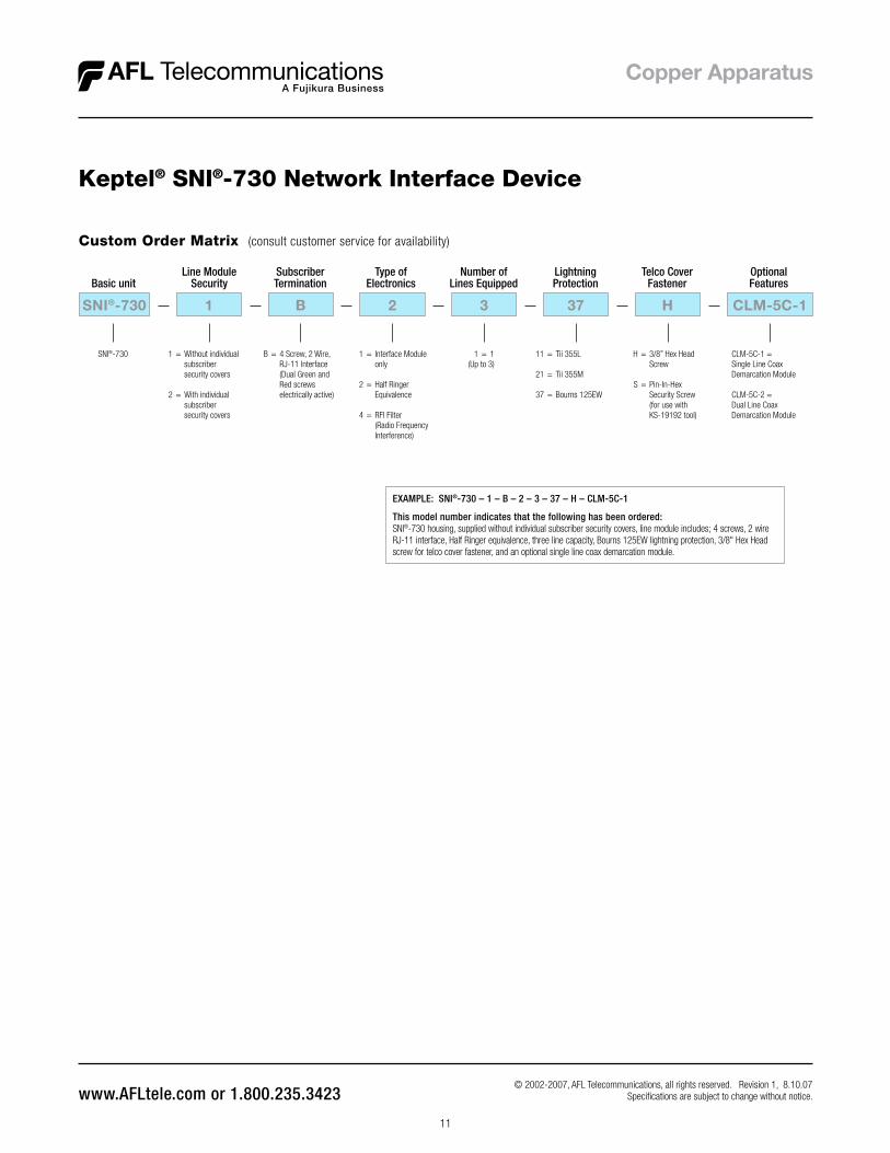
Keptel® SNI®-730 Network Interface Device
EXAMPLE: SNI®-730 – 1 – B – 2 – 3 – 37 – H – CLM-5C-1
This model number indicates that the following has been ordered:SNI®-730 housing, supplied without individual subscriber security covers, line module includes; 4 screws, 2 wire RJ-11 interface, Half Ringer equivalence, three line capacity, Bourns 125EW lightning protection, 3/8" Hex Head screw for telco cover fastener, and an optional single line coax demarcation module .
SNI®-730
SNI®-730
Basic unit
Custom Order Matrix (consult customer service for availability)
1
1 = Without individual subscriber security covers
2 = With individual subscriber security covers
Line Module Security
B
B = 4 Screw, 2 Wire, RJ-11 Interface (Dual Green and Red screws electrically active)
Subscriber Termination
2
1 = Interface Module only
2 = Half Ringer Equivalence
4 = RFI Filter (Radio Frequency Interference)
Type ofElectronics
3
1 = 1 (Up to 3)
Number of Lines Equipped
37
11 = Tii 355L
21 = Tii 355M
37 = Bourns 125EW
Lightning Protection
H
H = 3/8” Hex Head Screw
S = Pin-In-Hex Security Screw (for use with KS-19192 tool)
Telco Cover Fastener
CLM-5C-1
CLM-5C-1 =Single Line CoaxDemarcation Module
CLM-5C-2 =Dual Line CoaxDemarcation Module
OptionalFeatures
© 2002-2007, AFL Telecommunications, all rights reserved . Revision 1, 8 .10 .07 Specifications are subject to change without notice .
12
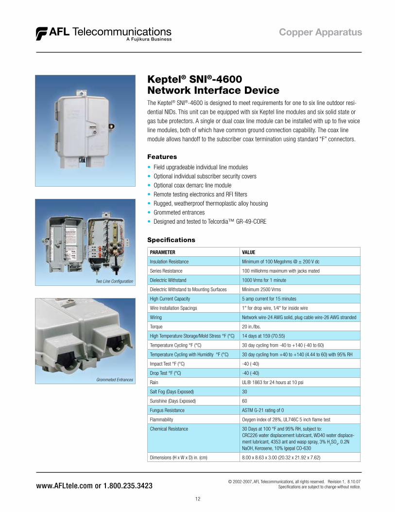
The Keptel® SNI®-4600 is designed to meet requirements for one to six line outdoor resi-dential NIDs . This unit can be equipped with six Keptel line modules and six solid state or gas tube protectors . A single or dual coax line module can be installed with up to five voice line modules, both of which have common ground connection capability . The coax line module allows handoff to the subscriber coax termination using standard “F” connectors .
Two Line Configuration
Grommeted Entrances
Keptel® SNI®-4600 Network Interface Device
Features
• Field upgradeable individual line modules• Optional individual subscriber security covers• Optional coax demarc line module• Remote testing electronics and RFI filters• Rugged, weatherproof thermoplastic alloy housing• Grommeted entrances• Designed and tested to Telcordia™ GR-49-CORE
Specifications
PARAMETER VALUE
Insulation Resistance Minimum of 100 Megohms @ ± 200 V dc
Series Resistance 100 milliohms maximum with jacks mated
Dielectric Withstand 1000 Vrms for 1 minute
Dielectric Withstand to Mounting Surfaces Minimum 2500 Vrms
High Current Capacity 5 amp current for 15 minutes
Wire Installation Spacings 1" for drop wire, 1⁄4" for inside wire
Wiring Network wire-24 AWG solid, plug cable wire-26 AWG stranded
Torque 20 in ./lbs .
High Temperature Storage/Mold Stress °F (°C) 14 days at 159 (70 .55)
Temperature Cycling °F (°C) 30 day cycling from -40 to +140 (-40 to 60)
Temperature Cycling with Humidity °F (°C) 30 day cycling from +40 to +140 (4 .44 to 60) with 95% RH
Impact Test °F (°C) -40 (-40)
Drop Test °F (°C) -40 (-40)
Rain UL® 1863 for 24 hours at 10 psi
Salt Fog (Days Exposed) 30
Sunshine (Days Exposed) 60
Fungus Resistance ASTM G-21 rating of 0
Flammability Oxygen index of 28%, UL746C 5 inch flame test
Chemical Resistance 30 Days at 100 °F and 95% RH, subject to: CRC226 water displacement lubricant, WD40 water displace-ment lubricant, 4353 ant and wasp spray, 3% H
2SO
4, 0 .2N
NaOH, Kerosene, 10% Igepal CO-630
Dimensions (H x W x D) in . (cm) 8 .00 x 8 .63 x 3 .00 (20 .32 x 21 .92 x 7 .62)
© 2002-2007, AFL Telecommunications, all rights reserved . Revision 1, 8 .10 .07 Specifications are subject to change without notice .

13
Standard Configurations
MODEL # PART #
SNI®-4600 - 1 - B - 1 - 1 - 21 - H 911306-00-00
SNI®-4600 - 1 - B - 1 - 2 - 21 - H 911647-00-00
SNI®-4600 - 1 - B - 1 - 6 - 21 - H 91627-00
SNI®-4600 - 1 - B - 1 - 1 - 37 - H DM000002
SNI®-4600 - 1 - B - 1 - 2 - 37 - H 911226-00-00
SNI®-4600 - 1 - B - 1 - 6 - 37 - H 911142-00
Keptel® SNI®-4600 Network Interface Device
Lock Staple/Telco OverrideA view of both the telco and subscriber locking mechanisms . The subscribercan access the unit with a standard screwdriver and a stainless steel lock staple is provided for individual security . Telco override is provided and can be accessed with a standard 216 tool(security fastener option also available) .
EXAMPLE: SNI®-4600 – 1 – BT – 2 – 3 – 43 – H – CLM-5-1
This model number indicates that the following has been ordered:SNI®-4600 housing, supplied without individual subscriber security covers, line module includes; 4 screws, 2 wire RJ-11 interface and a sealed RJ-11 ETO “Jumping Jack”, Half Ringer equivalence, three line capacity, Tii 126L1 lightning protection, 3/8" Hex Head screw for telco cover fastener, optional single line coax demarcation module .
SNI®-4600
SNI®-4600
Basic unit
Custom Order Matrix (consult customer service for availability)
1
1 = Without individual
subscriber
security covers
2 = With individual
subscriber
security covers
Line Module Security
BT
A = 2 Screw, 2 Wire,
RJ-11 interface
B = 4 Screw, 2 Wire,
RJ-11 Interface
(Green and Red
electrically active)
C = 6 screw, 2 wire,
Bridging Module
D = 4 screw, 4 wire,
RJ-14 Interface
(Green, Yellow, Red
and Black are
electrically active)
F = 2 screw, 8 position,
2 Wire Interface
(Special Services)
T = Sealed RJ-11 ETO
“Jumping Jack”
(n/a with C, D or F
termination above)
Subscriber Termination
2
1 = Interface Module
only
2 = Half Ringer
Equivalence
4 = RFI Filter
(Radio Frequency
Interference)
Type ofElectronics
3
1 = 1
(Up to 6)
Number of Lines Equipped
43
11 = Tii 355L
12 = Tii 356L
21 = Tii 355M
22 = Tii 356M1
37 = Joslyn 125EW
43 = Tii 126L1
65 = Lucent 25
68 = Tii MSP-350L
70 = Amp Quietfront I
71 = Amp Quietfront II
Lightning Protection
H
H = 3/8” Hex Head
Screw
S = Pin-In-Hex
Security Screw
(for use with
KS-19192 tool)
Telco Cover Fastener
CLM-5-1
CLM-5-1 =
Single Line Coax
Demarcation Module
CLM-5-2 =
Dual Line Coax
Demarcation Module
OptionalFeatures
© 2002-2007, AFL Telecommunications, all rights reserved . Revision 1, 8 .10 .07 Specifications are subject to change without notice .

14
The Keptel® SNI®-4300 is designed to meet requirements for one to three line outdoor residential NIDs . This unit can be equipped with three line modules and three solid state or gas tube protectors . A single or dual coax line module can be installed with up to two voice line modules, both of which have common ground connection capability . The coax line module allows handoff to the subscriber coax termination using standard “F” connectors .
Grommeted Entrances
Keptel® SNI®-4300 Network Interface Device
Features
• Field upgradeable individual line modules• Optional individual subscriber security covers• Optional coax demarc line module• Remote testing electronics and RFI filters• Rugged, weatherproof thermoplastic alloy housing• Grommeted entrances• Designed and tested to Telcordia™ GR-49-CORE
Specifications
PARAMETER VALUE
Insulation Resistance Minimum of 100 Megohms @ ± 200 V dc
Series Resistance 100 milliohms maximum with jacks mated
Dielectric Withstand 1000 Vrms for 1 minute
Dielectric Withstand to Mounting Surfaces Minimum 2500 Vrms
High Current Capacity 5 amp current for 15 minutes
Wire Installation Spacings 1" for drop wire, 1⁄4" for inside wire
Wiring Network wire-24 AWG solid, plug cable wire-26 AWG stranded
Torque 20 in ./lbs .
High Temperature Storage/Mold Stress °F (°C) 14 days at 159 (70 .55)
Temperature Cycling °F (°C) 30 day cycling from -40 to +140 (-40 to 60)
Temperature Cycling with Humidity °F (°C) 30 day cycling from +40 to +140 (4 .44 to 60) with 95% RH
Impact Test °F (°C) -40 (-40)
Drop Test °F (°C) -40 (-40)
Rain UL® 1863 for 24 hours at 10 psi
Salt Fog (Days Exposed) 30
Sunshine (Days Exposed) 60
Fungus Resistance ASTM G-21 rating of 0
Flammability Oxygen index of 28%, UL746C 5 inch flame test
Chemical Resistance 30 Days at 100 °F and 95% RH, subject to: CRC226 water displacement lubricant, WD40 water displace-ment lubricant, 4353 ant and wasp spray, 3% H
2SO
4, 0 .2N
NaOH, Kerosene, 10% Igepal CO-630
Dimensions (H x W x D) in . (cm) 6 .25 x 8 .00 x 3 .00 (16 .26 x 20 .32 x 7 .62)
© 2002-2007, AFL Telecommunications, all rights reserved . Revision 1, 8 .10 .07 Specifications are subject to change without notice .

15
Recessed Pockets/Rear Entry Port
Recessed pockets have been added below the subscriber line modules to tuck away electronic packages, keeping the main compartment uncongested . In addition, three optional grommeted entry portshave been added to the back of the unit, allowing I/W to pass directly from the home to the subscriber wiring bridge .
Lock Staple/Telco Override
A view of both the telco and subscriber locking mechanisms . The subscribercan access the unit with a standard screwdriver and a stainless steel lock staple is provided for individual security . Telco override is provided and can be accessed with a standard 216 tool(security fastener option also available) .
Keptel® SNI®-4300 Network Interface Device
© 2002-2007, AFL Telecommunications, all rights reserved . Revision 1, 8 .10 .07 Specifications are subject to change without notice .
OptionalFeatures
Telco Cover Fastener
Lightning Protection
11 = Tii 355L
12 = Tii 356L
21 = Tii 355M
22 = Tii 356M1
37 = Joslyn 125EW
43 = Tii 126L1
65 = Lucent 25
68 = Tii MSP-350L
70 = Amp Quietfront I
71 = Amp Quietfront II
Number of Lines Equipped
1 = 1
(Up to 3)
Type ofElectronics
1 = Interface Module
only
2 = Half Ringer
Equivalence
4 = RFI Filter
(Radio Frequency
Interference)
Subscriber Termination
A = 2 Screw, 2 Wire,
RJ-11 interface
B = 4 Screw, 2 Wire,
RJ-11 Interface
(Green and Red
electrically active)
C = 6 screw, 2 wire,
Bridging Module
D = 4 screw, 4 wire,
RJ-14 Interface
(Green, Yellow, Red
and Black are
electrically active)
F = 2 screw, 8 position,
2 Wire Interface
(Special Services)
T = Sealed RJ-11 ETO
“Jumping Jack”
(n/a with C, D or F
termination above)
Line Module Security
1 = Without individual
subscriber
security covers
2 = With individual
subscriber
security covers
SNI®-4300
SNI®-4300
Basic unit
1 BT 2 2 43 H
H = 3/8” Hex Head
Screw
S = Pin-In-Hex
Security Screw
(for use with
KS-19192 tool)
CLM-5-1
CLM-5-1 =
Single Line Coax
Demarcation Module
CLM-5-2 =
Dual Line Coax
Demarcation Module
Custom Order Matrix (consult customer service for availability)
EXAMPLE: SNI®-4300 – 1 – BT – 2 – 2 – 43 – H – CLM-5-1
This model number indicates that the following has been ordered:SNI®-4300 housing, supplied without individual subscriber security covers, line module includes; 4 screws, 2 wire RJ-11 interface and a sealed RJ-11 ETO “Jumping Jack”, Half Ringer equivalence, two line capacity, Tii 126L1 lightening protection, 3/8" Hex Head screw for telco cover fastener, optional single line coax demarcation module .

16
The Keptel® SNI®-1100 is the perfect solution for your one-line outdoor residential Network Interface Device (NID) needs . The unit is equipped with a single line modular jack for subscriber testing and is available, on a custom order basis, with a wide variety of lightning protection . In addition, a half-ringer equivalent circuit can installed in the SNI®-1100 .
Keptel® SNI®-1100 Network Interface Device
Features
• Rugged, weatherproof thermoplastic alloy housing• Grommeted entrances• Designed and tested to Telcordia™ GR-49-CORE
Specifications
PARAMETER VALUE
Insulation Resistance Minimum of 100 milliΩ @ ± 200 V dc
Series Resistance 100 mΩ maximum with jacks mated
Dielectric Withstand 1000 Vrms for 1 minute
Dielectric Withstand to Mounting Surfaces Minimum 2500 Vrms
High Current Capacity 5 amp current for 15 minutes
Wire Installation Spacings 1" for drop wire, 1⁄4" for inside wire
Wiring Network wire-24 AWG solid, plug cable wire-26 AWG stranded
Torque 20 in ./lbs .
High Temperature Storage/Mold Stress °F (°C) 14 days at 159 (70 .55)
Temperature Cycling °F (°C) 30 day cycling from -40 to 140 (-40 to 60)
Temperature Cycling with Humidity °F (°C) 30 day cycling from 40-140 (4 .44-60) with 95% RH
Impact Test °F (°C) -40 (-40)
Drop Test °F (°C) -40 (-40)
Rain U .L .® 1863 for 24 hours at 10 psi
Salt Fog (Days Exposed) 30
Sunshine (Days Exposed) 60
Fungus Resistance ASTM G-21 rating of 0
Flammability Oxygen index of 28%, UL746C 5 flame test
Chemical Resistance30 Days at 100 °F and 95% RH Subject to:
CRC226 water displacement lubricant, WD40 water displace-ment lubricant, 4353 ant and wasp spray, 3% H
2SO
4, 0 .2N
NaOH, Kerosene, 10% Igepal CO-630
Dimensions (H x W x D) in . (cm) 6 .25 x 5 .87 x 2 .5 (20 .32 x 21 .92 x 7 .62)
© 2002-2007, AFL Telecommunications, all rights reserved . Revision 1, 8 .10 .07 Specifications are subject to change without notice .
17
Standard Configurations
MODEL # PART #
SNI®-1100 - 1 - X - H 90160-01
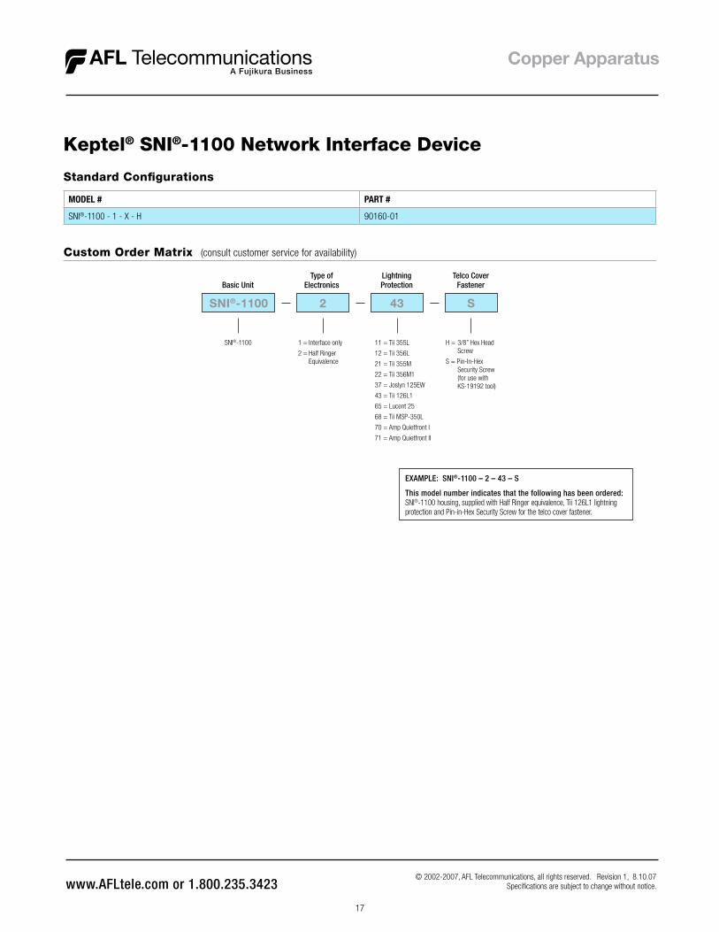
Keptel® SNI®-1100 Network Interface Device
EXAMPLE: SNI®-1100 – 2 – 43 – S
This model number indicates that the following has been ordered:SNI®-1100 housing, supplied with Half Ringer equivalence, Tii 126L1 lightning protection and Pin-in-Hex Security Screw for the telco cover fastener .
Custom Order Matrix (consult customer service for availability)
SNI®-1100
Basic Unit
SNI®-1100
1 = Interface only
2 = Half Ringer Equivalence
Type ofElectronics
2 43
11 = Tii 355L
12 = Tii 356L
21 = Tii 355M
22 = Tii 356M1
37 = Joslyn 125EW
43 = Tii 126L1
65 = Lucent 25
68 = Tii MSP-350L
70 = Amp Quietfront I
71 = Amp Quietfront II
Lightning Protection
S
H = 3/8” Hex Head Screw
S = Pin-In-Hex Security Screw (for use with KS-19192 tool)
Telco Cover Fastener
© 2002-2007, AFL Telecommunications, all rights reserved . Revision 1, 8 .10 .07 Specifications are subject to change without notice .

18
The Keptel® ML-6 is a compact six-line Indoor Network Interface Device . The ML-6 incorporates the standard Line Module footprint . The ML-6 is decorative in styling, allowing it to be placed in the open rather than hidden inside a closet . The ML-6 features telco and subscriber grommeted cable ports, areas for recording subscriber phone numbers and operating instructions engraved into the covers of the unit . The ML-6 comes equipped with four grommeted ports in the subscriber compartment for convenient wire routing . Three grommeted ports are provided in the telco compartment as well . This feature allows the units to be stacked vertically, ideal for those occasions where space is limited .
Three Line Configuration
Subscriber Compartment Grommets
Keptel® ML-6 Indoor Network Interface Device
Features
• One to six lines, field upgradeable• Stackable design• Utilizes Keptel patented standard line
module footprint
Specifications
PARAMETER VALUE
Insulation Resistance Minimum of 100 Megohms @ ± 200 V dc
Series Resistance 100 milliohms maximum with jacks mated
Dielectric Withstand 1000 Vrms for 1 minute
Dielectric Withstand to Mounting Surfaces Minimum 2500 Vrms
High Current Capacity 5 amp current for 15 minutes
Wire Installation Spacings 1" for drop wire, 1⁄4" for inside wire
Wiring Network wire-24 AWG solid, plug cable wire-26 AWG stranded
Torque 20 in ./lbs .
High Temperature Storage/Mold Stress °F (°C) 7 days at 158 (70)
Temperature Cycling °F (°C) 30 day cycling from -40 to 120 (-40 to 48 .88)
Temperature Cycling with Humidity °F (°C) 30 day cycling from 40-140 (4 .44-60) with 95% RH
Impact Test °F (°C) 77 (25)
Drop Test °F (°C) 77 (25)
Rain UL® 1863 for 24 hours at 10 psi
Salt Fog (Days Exposed) 30
Sunshine (Days Exposed) 60
Fungus Resistance ASTM G-21 rating of 0
Flammability Oxygen index of 28%, UL746C 5 inch flame test
Chemical Resistance 30 Days at 100 °F and 95% RH, subject to:
CRC226 water displacement lubricant, WD40 water displacement
lubricant, 4353 ant and wasp spray, 3% H2SO
4, 0 .2N NaOH, Kerosene,
10% Igepal CO-630
Paint Intrusion NID shall not be susceptible to paint intrusion
Dimensions (H x W x D) in . (cm) 7 x 6 x 2 .5 (17 .78 x 15 .24 x 6 .35)
• Integral network wiring bridge with optional stub cable
• Side entry grommets for telco and subscriber wiring
• Decorative contoured styling
© 2002, AFL Telecommunications, all rights reserved . Revision 0, 4 .01 .05 Specifications are subject to change without notice .

19
Keptel® ML-6 Indoor Network Interface Device
Custom Order Matrix (consult customer service for availability)
ML-6
ML-6
Basic unit
2
1 = Without individual subscriber security covers
2 = With individual subscriber security covers
Line Module Security
BT
Subscriber Termination
1
Type of Electronics
6
Number of Lines Equipped
H
Telco Cover Fastener
A = 2 Screw, 2 Wire, RJ-11 interface
B = 4 Screw, 2 Wire, RJ-11 Interface (Green and Red electrically active)
C = 6 screw, 2 wire, Bridging Module
D = 4 screw, 4 wire, RJ-14 Interface (Green, Yellow, Red and Black are electrically active)
F = 2 screw, 8 position, 2 Wire Interface (Special Services)
T = Sealed RJ-11 ETO “Jumping Jack” (n/a with C, D or F termination above)
1 = Interface Module only
2 = Half Ringer Equivalence
4 = RFI Filter (Radio Frequency Interference)
1 = 1 (up to 6) H = 3/8” Hex Head Screw
S = Pin-In-Hex Security Screw (for use with KS-19192 tool)
EXAMPLE: ML-6 – 2– BT – 1 – 6 – H
This model number indicates that the following has been ordered:ML-6 unit, supplied with individual subscriber security covers, 4 screws, 2-wire RJ-11 interface and a sealed RJ-11 ETO “Jumping Jack” interface circuit module (interface only), six line capacity, 3/8" hex head screw for telco cover fastener .
Standard Configurations
MODEL # PART #
ML-6 - 1 - B - 1 - 1 - H 912047-00-00
© 2002, AFL Telecommunications, all rights reserved . Revision 0, 4 .01 .05 Specifications are subject to change without notice .

20
Keptel® Line Modulesfor Network Interface DevicesThe strength of the Keptel® Network Interface Device (NID) product line lies in our versatile family of Line Interface Modules . The standard Keptel Line Interface Module footprint has been an integral part of the NID market for over 10 years and over 15 million NIDs have been deployed throughout the country .
Specifications
PARAMETER VALUE
Contact Construction 50 micro inches hard gold / 100 micro inches nickel plated phosphor bronze
Contact Force Minimum 100 grams
Temperature Cycling with Humidity 30 day cycling from 40-120°F (4 .44-48 .88°C) with 90% RH
SEALED LINE MODULEImmersion (Flooded Conditions) RJ-11 jack immersed in a solution of 1% weight sodium chloride (NaCl)
and distilled deionized water, placed at a depth of 12 inches, or at a temperature of 77 °F for a period of three days . A bias of -48 V dc was applied between tip and ring of the jack during immersion
COAX MODULEImpedance
Insertion LossReturn Loss
“F” ConnectorCoax Cable
RF Shielding
75 ohms< 0 .12 dB maximum, 5 MHz-1 GHz< 21 dB minimum, 5 MHz-1 GHzMeets SCTE specification IPS-SP-400Conforms to MIL-C-17/94F specification100 dB, 5 MHz to 1 GHz, tested per MIS-20097D
Standard Configurations
MODEL # PART #
KIT UPGRADE 1B-1 / 125 PROTECTOR DM000003
KIT UPGRADE 1B-1 / 355 PROTECTOR DM000004
KIT UPGRADE 1B-1 90829
KIT BUNCH BLOCK 911322-00-00
Features
• Field upgradeable• Standard Keptel line module footprint• Self-contained, simply press in place• Available with half ringers and RFI filters• Line modules used in: SNI®-4600, SNI®-4300, SNI®-4600XL, ML-6 and SNI®-1212• Optional individual subscriber security cover available• UL® Listed in Keptel Network Interface Systems and Closures
© 2002-2007, AFL Telecommunications, all rights reserved . Revision 1, 8 .10 .07 Specifications are subject to change without notice .

21
Keptel® Line Modules for Network Interface Devices
Typical Configurations
1A-4 Module(RFI Filter Module)
2B-1 Module(Security Cover)
1D-1 Module(RJ-14 Module)
1C-1 Module(Bunch Block)
CLM-5-1 Module(Coax Module)
Consult customer service for ordering information.
Custom Order Matrix (consult customer service for availability)
2 BT
SubscriberTermination
1
Type of Electronics
Line Module Security
1 = Without individual subscriber security covers
2 = With individual subscriber security covers
A = 2 Screw, 2 Wire, RJ-11 interface
B = 4 Screw, 2 Wire, RJ-11 Interface (Green and Red electrically active)
C = 6 screw, 2 wire, Bridging Module
D = 4 screw, 4 wire, RJ-14 Interface (Green, Yellow, Red and Black are electrically active)
F = 2 screw, 8 position, 2 Wire Interface (Special Services)
T = Sealed RJ-11 ETO “Jumping Jack” (n/a with C, D or F termination above)
1 = Interface Module only
2 = Half Ringer Equivalence
4 = RFI Filter (Radio Frequency Interference)
37
LightningProtection
21 = Tii 355M
37 = Joslyn 125EW
© 2002-2007, AFL Telecommunications, all rights reserved . Revision 1, 8 .10 .07 Specifications are subject to change without notice .
2BT-1 Module(Sealed Module)
EXAMPLE: 2 – BT – 1 – 37
This model number indicates that the following has been ordered:A Line Module, supplied with an individual subscriber security cover, 4 screws, 2-wire RJ-11 interface and a sealed RJ-11 ETO “Jumping Jack” interface circuit module (interface only) and is supplied with a Joslyn 125EW lightning protector .

22
Keptel® SNI®-8925Multiline Network Interface DeviceThe Keptel® SNI®-8925 is a patented, ultra-compact, economical, Network Interface Device (NID) designed for 25-pair multiline applications . Twenty-five individual RJ-11 jacks provide the interface at the demarcation point as specified in FCC Part 68 requirements, allowing testing at the subscriber’s location for each individual feeder pair provided . This line testing feature could reduce T&M charges on maintenance calls, since the subscriber would now be able to test their own individual lines to determine which side of demarc the fault resides before calling for service .
Specifications
PARAMETER VALUE
Construction Precision injection-molded from rugged engineering thermoplastic
Plugs and Jacks 50 micro inches of hard gold over 100 micro inches of nickel-plated phosphor bronze
Terminal Screws Plastic head, stainless steel 1⁄4" hex-slotted multi-washer (brass) screws
Insulation Displacement Connectors(66 clip and Snap-lock IDC)
Tin plated over phosphor bronze
Mounting Frame, wall or backboard using attached standard 89D or 89B brackets (order without mounting bracket if bracket exists)
Benefits
• Mounts anywhere a 66M block would• Compact 25-pair network interface• Optional remote half ringer test electronics• Rugged thermoplastic alloy housing• Telco termination: 50-pin or AT&T 710 connector on back• Subscriber termination: screw, IDC, 66-clip• Mounts to 89B or 89D bracket• Optional weatherable version for use in BET/NIDs• UL® listed and patented (No . 4,932,051)/Telcordia™ tested• Integral I/W strain relief for each individual pair
25-Pair Rear Connector
Standard Configurations
MODEL # PART #
SNI®-8925 - 1 - 1 - 1 90365-02
SNI®-8925 - 7 - 1 - 2 91669-00
© 2002-2007, AFL Telecommunications, all rights reserved . Revision 1, 8 .10 .07 Specifications are subject to change without notice .

23
Keptel® SNI®-8925 Multiline Network Interface Device
Custom Order Matrix (consult customer service for availability)
SNI®-8925
SNI®-8925
Basic unit
1
1 = Male 50-Pin Connector, Network Side, Screw Terminals, Subscriber Side
2 = Male 50-Pin Connector, Network Side, 66 Clips Subscriber Side
3 = Male 50-Pin Connector, Network Side, No Wiring Bridges, Subscriber Side
4 = N/A (Discontinued Option)
5 = Male 50-Pin Connector, Network Side, Snap-Lock IDC, Subscriber Side
6 = AT&T 710 Connector, Network Side, Screw Terminals, Subscriber Side
7 = AT&T 710 Connector, Network Side, Screw Terminals, Subscriber Side, Weather Resistant Rubber Boots Covering RJ-11 Jacks
Line Module Security
1
Type of Electronics
1Attachments
1 = Interface Module only
2 = Half Ringer Equivalence
1 = With 89D Mounting Bracket
2 = Without Mounting Bracket Supplied
3 = With 89B Mounting Bracket
EXAMPLE: SNI®-8925 – 1– 1 – 1
This model number indicates that the following has been ordered:SNI®-8925 Multiline Network Interface Device, Male 50-pin connector on network side, screw terminals on subscriber side, Interface only, with 89D mounting bracket .
Multi-Washer Screws
• Two screws with four washers each allow the termination of up to four wires per screw• Plastic 1⁄4" slotted hex heads prevent accidental casual contact from the subscriber• Optional weather resistant rubber boots cover RJ-11 jacks for outdoor applications
Multi-Washer Screws
Snap-Lock IDC
66 Style Clip
Snap-Lock IDC
• Individual pairs can be terminated to the SNI-8925 without the use of hand tools• Swinging cover makes the connection when closed by pushing conductors into contacts• The Snap-Lock IDC is for indoor use only
66 style clip
• Dual 66-clips allow termination of up to two wires per clip• Uses the same tool as traditional 66 style blocks• Recommended for quick cross-connect capability when used with 66 blocks• The 66 style clip is recommended for indoor use only
MPOP demarcation system
• Mounted on quick connect type racks• 300-2400 pair applications requiring demarcation located at minimum point of penetration• Anywhere floor and wall space are a premium• Preterminated stub cables on network side reduce installation time by as much as 50%• Each system 100% pretested to eliminate troubleshooting on the job site
MPOP Rack
© 2002-2007, AFL Telecommunications, all rights reserved . Revision 1, 8 .10 .07 Specifications are subject to change without notice .

24
The SNI®-2125 is a compact Network Interface Device (NID) designed for 25-pair indoor applications . Constructed of a thermoplastic alloy and the highest quality components, the SNI®-2125 is designed to provide years of uninterrupted service . The SNI®-2125 is provided with a male 50-pin connector for the network connection (66-type punchdown clips are optional) and press-fit wiring bridges featuring multi-washer screws on the subscriber side . The SNI®-2125 can be stacked vertically for greater than 25-pair appli-cations . The unit is available without the subscriber wiring bridges for use as a 50-pin to RJ-11 adapter or patch block .
Specifications
PARAMETER VALUE
Construction Precision injection-molded from rugged engineering thermoplastic
Plugs and Jacks 50 micro inches of hard gold over 100 micro inches of nickel-plated phosphor bronze
Terminal Screws Plastic head, stainless steel 1⁄4" hex-slotted multi-washer (brass) screws
Mounting Wall or backboard via mounting feet
Dimensions (H x W x D) 16 .25” x 5 .13” x 1 .63”
Benefits
• 25-pair network interface• Optional remote half ringer electronics• Rugged thermoplastic alloy housing• 50-pin connector or optional 66-type
punchdown on network side• Multi-washer screws on subsciber side• Field replaceable wiring bridges• Stack units vertically
Custom Ordering Matrix
SNI®-2125
SNI®-2125
Basic unit
1
1 = Male 50-Pin Connector on Network Side, Screw Terminals on Subscriber Side
2H = 66 Clips on Network Side (3/8” Cover Fastener), Screw Terminals on Subscriber Side
2S = 66 Clips on Network Side (Security Cover Fastener), Screw Terminals on Subscriber Side
5 = Male 50-Pin Connector on Network Side, No wiring Bridge on Subscriber Side
Termination
1
Type of Electronics
1 = Interface Module only
2 = Half Ringer Equivalence
EXAMPLE: SNI®-2125 – 1 – 1
This model number indicates that the following has been ordered:SNI®-2125 Multiline Network Interface Device, Male 50-pin connector on network side, screw terminals on subscriber side, Interface only .
Keptel® SNI®-212525-Pair Network Interface Device
Standard Configurations
MODEL # PART #
SNI-2125 Consult AFL Customer Service
© 2002-2007, AFL Telecommunications, all rights reserved . Revision 1, 8 .10 .07 Specifications are subject to change without notice .

25
Keptel® 1642 Termination Enclosure
Ordering Information
DESCRIPTION MODEL # PART #
1642 Enclosure with Keptel # 90313 Terminal Block (6-Pair) 1642-1-34 90379
1642 Enclosure with six 125-style Gas Tube Protectors 1642-1-37 DM000124
1642 Enclosure with six IDC Terminals 1642-1-95 DM000254
1642 Hanging Hardware Kit (for 5/16” to 7/16” strand) 1642 Hanging Hardware 90323
The Keptel® 1642 termination enclosure can be outfitted with heavy plated steel hangers designed to grip the support strand and prevent rotation . Internal punch-out holes allow for wall or pole mounting . Stainless steel lashing straps can be mounted through punch-outs for pole, post or piling mounting .
© 2002, AFL Telecommunications, all rights reserved . Revision 0, 10 .03 .05 Specifications are subject to change without notice .
Features
• An alternative to the 116 or 104 closure• Corrosion and weatherproof• Pole or wall mountable• Quarter-turn stainless steel cover fastener• Eight grommeted cable entry/exit ports• Houses 142 and 57 style protectors• Accepts AFL Telecommunications, AT&T and Reliable terminal blocks• Available with binding post, IDC or gas tube protection .• Impact and chemical resistant engineered thermoplastic

26
Keptel® 1642XLTermination Enclosure
Ordering Information
DESCRIPTION MODEL # PART #
1642XL enclosure, empty, no strand hanging hardware included 1642XL 912809-00-00
1642 Hanging Hardware Kit (for 5/15” to 7/16” strand) 1642 Hanging Hardware Kit 90323
© 2004, AFL Telecommunications, all rights reserved . Revision 1, 5 .11 .06 Specifications are subject to change without notice .
Features
• An alternative to the 116 or 104 closure• Corrosion and weatherproof• Pole or wall mountable• Quarter-turn stainless steel cover fastener• Eight grommeted cable entry/exit ports• Houses 142 and 57 style protectors• Accepts AFL Telecommunications, AT&T and Reliable terminal blocks• Impact and chemical resistant engineered thermoplastic
The Keptel® 1642 termination enclosure can be outfitted with heavy plated steel hangers designed to grip the support strand and prevent rotation . Internal punch-out holes allow for wall or pole mounting . Stainless steel lashing straps can be mounted through punch-outs for pole, post or piling mounting .

27
Keptel® 1642 IDC Terminal Enclosure
Ordering Information
DESCRIPTION MODEL # PART #
1642 IDC Terminal Enclosure 1642 IDC DM000254
1642 Hanger Bracket Kit (for 5/16” to 7/16” strand) 1642 Hanging Hardware Kit 90323
The Keptel 1642 IDC Terminal Enclosure is a 6-pair sealed termination device for copper conductors . It can be used in aerial, pole or wall mount applications and is equipped with six (6) pre-installed individual IDC termination modules mounted onto a single common ground bus bracket . The bus bracket also allows common bonding of ground wire, sheath armor and/or strand wire .
The 1642 IDC Terminal Enclosure is uniquely designed to withstand harsh environments, such as high moisture and coastal areas . The enclosure meets all Telcordia requirements stipulated in GR-975 for sealing and GR-1195 for IDC Cross-connect and Terminal Blocks .
The IDC termination modules require no stripping of the copper wire insulation prior to connection . In addition, each module has two (2) ports for small gauge (22-24 AWG) wire terminations and two (2) ports that accept large gauge (18-19 AWG) or small gauge (22-24 AWG) wire for tip/ring connections . The ports are color coded for easy tip/ring identification .
The 1642 IDC Terminal Enclosure also features eight (8) individually grommeted entry/exit ports for multiple drop wire installations . The unit features a ¼ turn fastener for easy open/close access using a 216 tool (can wrench) . Labelling inside the cover allows for line identification of each IDC termination module along with illustrated installation instructions .
© 2006, AFL Telecommunications, all rights reserved . Revision 0, 2 .09 .06 Specifications are subject to change without notice .
Features
• Individual gel-sealed IDC termination modules pre-installed• 18-24 AWG copper wire termination• Thermoplastic weatherproof enclosure• UV resistant• Impact resistant• Chemical resistant• Flame retardant• Quarter-turn 216 locking fastener• Eight individual entry/exit ports• Aerial, wall or pole mount applications• Optional strand hanger brackets• UL listed• Craft-friendly design
28
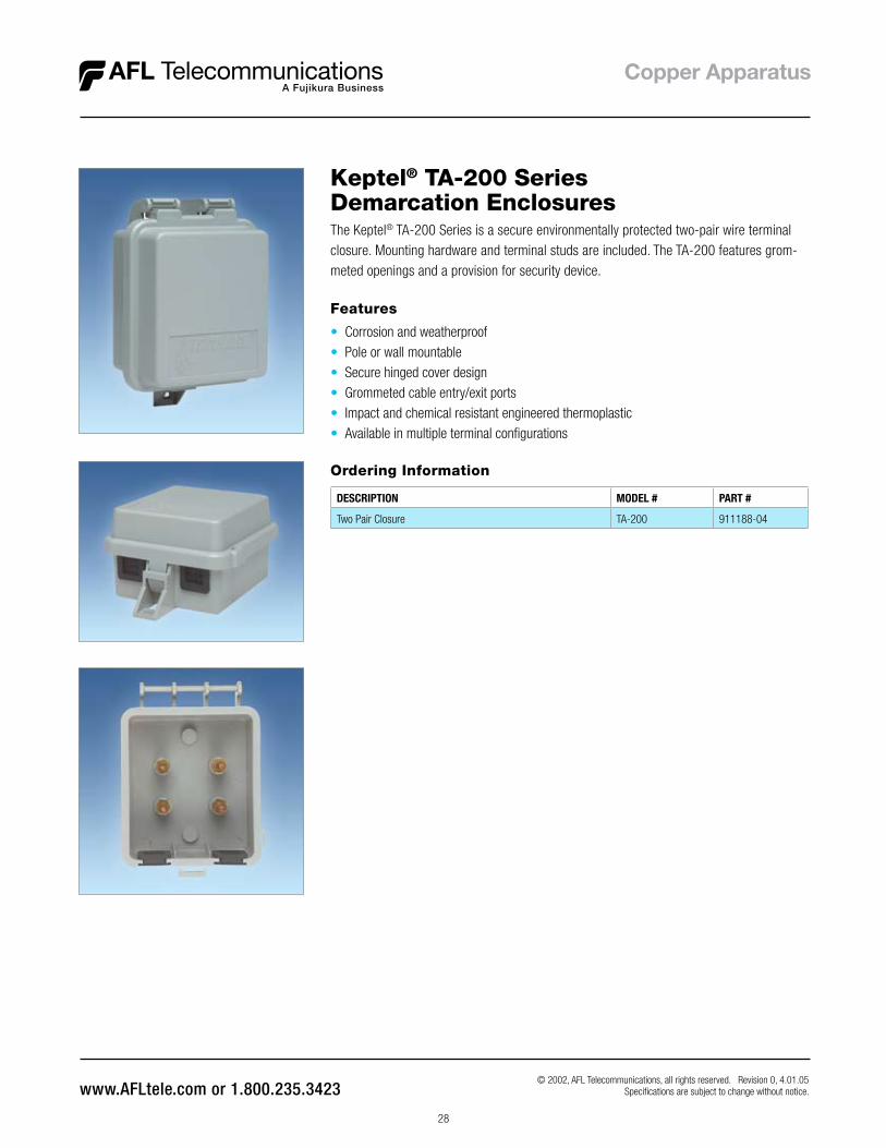
Keptel® TA-200 Series Demarcation Enclosures
Ordering Information
DESCRIPTION MODEL # PART #
Two Pair Closure TA-200 911188-04
The Keptel® TA-200 Series is a secure environmentally protected two-pair wire terminal closure . Mounting hardware and terminal studs are included . The TA-200 features grom-meted openings and a provision for security device .
© 2002, AFL Telecommunications, all rights reserved . Revision 0, 4 .01 .05 Specifications are subject to change without notice .
Features
• Corrosion and weatherproof• Pole or wall mountable• Secure hinged cover design• Grommeted cable entry/exit ports• Impact and chemical resistant engineered thermoplastic• Available in multiple terminal configurations

29
Keptel® LPF-200 Series ADSL POTS SplittersAFL Telecommunications’ line of ADSL NID POTS Splitter solutions meets most indoor and outdoor requirements for single-line applications . Packaged in the standard Keptel® Line Module footprint, we have developed a solution that easily fits into most NIDs as a CPE device . The module occupies only one position within the NID and is housed in a plastic shell and encapsulated to provide an environmentally sealed product . All direct inside wiring connections to the module interface to colored, plastic coated washer screws .
Features
• Single width line module footprint is space efficient
• Environmentally sealed• Same splitter used with adjunct box
applications reduces inventory• Installs in a variety of NIDs• Quick mounting capability in front of or
behind existing indoor wall jacks without drilling mounting holes or replacing existing phone jack
• Low voice band insertion loss and flat voice band attenuation distortion
• Compatible with both CAP and DMT• Meets the ANSI T1 .413 Annex E, ITU-T
992 .1 Type 2 North American and Telcordia™ requirements
• UL® 1863 Listed
Specifications
PARAMETER VALUE
DC Loop Current (mA) 0-10
DC Resistance (ohms) < 19
Insertion Loss (1004 Hz) 0 .5 dB maximum; 0 .2 dB typical (ZTc @ 900, ZTr @ 600)
Attenuation Distortion ±0 .2 dB; 200-3400 Hz (ZTc @ 900, ZTr @ 600)
(Relative to Loss @ 1004 Hz) ±0 .3 dB; 200-4000 Hz (ZTc @ 900, ZTr @ 600)
Delay Distortion < 85 mSec from 200-4000 Hz
Return Loss (Voice Band) 13 dB ERL; 10 dB SRL-Low; 14 dB SRL-High
Longitudinal Balance; Two Port Technique > 80 dB; 200-2 kHz , 0-30 mA> 60 dB; 2-4 kHz , 0-30 mA
Tip-to-Ring Capacitance (POTS Port) < 100 nF; 20-30 Hz
ADSL Band Attenuation > 65 dB; 25-1104 kHz
Input Impedance (ADSL Band Signal Path Loading) 0 .1 dB from 30-1104 kHz
Operating Temperature °F (°C)LPF-200, LPF-200DLPF-200W, LPF-200F
-40 to 158 (-40 to 70)32-158 (0-70)
Relative Humidity (Non condensing) 0-95%
Fault Current Immunity Complies to GR-1089 levels I & II Surge and Power Cross
Dimensions (H x W x D) in . (cm)LPF-200LPF-200DTA-230
2 .05 x 0 .98 x 2 .20 (5 .21 x 2 .49 x 5 .59)0 .83 x 1 .35 x 1 .80 (2 .11 x 3 .43 x 4 .57)2 .50 x 3 .82 x 5 .45 (6 .35 x 9 .70 x 13 .84)
Weight lbs . (kg)LPF-200LPF-200DTA-230
0 .16 (0 .07)0 .13 (0 .58)0 .30 (0 .14)
NOTE: In-line Micro Filter and Central Office POTS Splitters are available; Contact your sales representative for ordering information
© 2002-2007, AFL Telecommunications, all rights reserved . Revision 1, 8 .10 .07 Specifications are subject to change without notice .
Standard Configurations
MODEL # PART #
LPF-200 ADSL POTS Splitter 911929-00-01
TA-230 Adjunct Box 911960-00-02

30
Keptel® LPF-200 Series ADSL POTS Splitters
LPF-200
• For installation on the CPE side of NID - single width line module package
• Flying leads permit universal connection to any style line module
• Multiple home runs are terminated through four washer screw handoffs
• Fits into SNI®-4300, SNI®-4600, ML-6, TA-230 and Siecor® CAC-7600 NIDs
TA-230 adjunct box
• Weathertight enclosure used when no open positions are available in NID
• Supports LPF-200 or LPF-200D POTS Splitter Module, eliminates need to inventory unique Adjunct Box Splitter
• Wall or Pole mountable• Available empty or with the LPF-
200/LPF-200D Module installed and terminated to screw bosses
© 2002-2007, AFL Telecommunications, all rights reserved . Revision 1, 8 .10 .07 Specifications are subject to change without notice .
LPF-200D (consult customer service for availability)
• For installation on the CPE side of NID - single width line module package
• RJ-11 terminated cable interfaces for quick installations; simple enough for a customer to complete installation
• I/W homeruns remain undisturbed on the line module terminal screws during installation or removal
• Fits into SNI®-4300, SNI®-4600, ML-6, TA-230 and Siecor® CAC-7600 NIDs

31
Keptel® Radio Frequency Interference Filter (RFI)The Keptel® Radio Frequency Interference Filter (RFI-P) is customer premise installed inside the Station Network Interface . It is designed to block unwanted RF energy as well as bypass RF energy to earth ground, while remaining transparent to normal loop signaling and test voltages . Using the earth ground connection, this filter acts like a drain: pro- viding a path to ground for the RF energy to bleed off the phone line from both the network and customer side of the network interface . It effectively eliminates all common mode and differential mode RF interference induced on the phone line in the vicinity of the RFI-P filter .
Laboratory Testing
Laboratory results presented here demonstrate that the RFI-P Filter introduces greater attenuation over a broader bandwidth when compared to the Telcordia™ requirement
© 2002, AFL Telecommunications, all rights reserved . Revision 0, 4 .01 .05 Specifications are subject to change without notice .
Features
• Suppresses RF interference across AM, FM, CB, VHF, TV, Amateur and UHF band
• Maximum suppression occurs in the AM band
• Bypasses unwanted RF energy to earth ground
• Excellent balance between Tip and Ring• Eliminates all common mode and
differential mode RF interference• Designed for use in outdoor or indoor
Network Interface Devices at the customer premise
• Transparent to normal loop signaling and test voltages
Ordering Information
DESCRIPTION MODEL # PART #
RFI circuit environmentally encapsulated with spade ended wire leads RFI-P 90931
Block Diagram / Connections / Dimensions

32
Half Ringer Equivalent CircuitThe Keptel® Half Ringer Equivalant Circuit allows automatic or manual testing to be performed from the central office without interrupting service to the customer . The Half Ringer, when connected in parallel with the phone line, poses a 0 .5 REN load . The Half Ringer is available in three different packages for both indoor and outdoor use and can be used in a variety of applications . Factory installation in a number of Network Interfaces Devices is available, please consult AFL Customer Service for specifics .
HR-100
1B-2 Module
HR-66T
© 2002, AFL Telecommunications, all rights reserved . Revision 0, 4 .01 .05 Specifications are subject to change without notice .
Features
• Available in a variety of packaging• 0 .5 Ringer Equivalance• Installed parallel to the line• Versions available for indoor or outdoor (ruggedized) use
Ordering Information
DESCRIPTION MODEL # PART #
Half Ringer installed in a ruggedized thermoplastic shell, installs easliy in Network Interface units for outdoor use
HR-100 90462
Half Ringer installed in a Keptel® standard footprint two-wire line module for use in Network Interface Devices
1B-2 90830-01
Half Ringer packaged to retrofit onto a 66-type punch-down block, provides bridged test points
HR-66T 911338-00-00