Embed Size (px)
Citation preview
5 November 2020 Version 5.0
© Elexon 2020 Page 1 of 18
C O P 4
C O M M I S S I O N I N G O F
M E A S U R E M E N T
T R A N S F O R M E R S O F
S E T T L E M E N T
P U R P O S E S
Guidance Note
Public
CoP 4 Commissioning of Measurement Transformers of Settlement Purposes
5 November 2020 Version 5.0
© Elexon 2020 Page 2 of 18
Contents
Contents 2
Commissioning of measurement transformers for Settlement purposes (Code of Practice 4) 3
Background 3
Process 4
Scenarios 5
Scenario 1 5
LDSO/NETSO Process 5
MOA Process 5
Registrant process 6
Scenario 2 6
LDSO Process 6
MOA Process 6
Registrant process 7
Scenario 3 7
System Operator Process 7
MOA Process 7
Registrant process 8
Scenario 4 8
LDSO Process 8
MOA Process 8
Registrant process 9
Scenario 5 9
LDSO Process 9
MOA Process 9
Registrant process 9
Scenario 6 10
MOA Process 10
Registrant process 10
Sample Measurement Transformers Commissioning Record 10
Risk Matrix 16
Process flow diagram 17
Further Information? 18
CoP 4 Commissioning of Measurement Transformers of Settlement Purposes
5 November 2020 Version 5.0
© Elexon 2020 Page 3 of 18
Commissioning of measurement transformers for Settlement purposes (Code of Practice 4)
This guidance provides information regarding the Balancing and Settlement Code (BSC) requirements for the
commissioning of Half Hourly Metering Equipment in accordance with Code of Practice 4 ‘The calibration, testing
and commissioning requirements of Metering Equipment for Settlement Purposes’ (CoP4).
Background
CoP4 sets out the requirement for commissioning, testing and the calibration of all Metering Equipment for Settlement
purposes. A BSC Modification, P283 ‘Reinforcing the Commissioning of Metering Equipment Processes’, made
changes to the BSC and CoP4 on 6 November 2014 with respect to the commissioning and testing of Metering
Equipment responsibilities.
The roles and responsibilities for all commissioning and calibration requirements as set out in the BSC and CoP4, the
overall responsibly rests with the Registrant1 . Commissioning under CoP4 is required when new equipment is
installed.
P283 has introduced a distinction where measurement transformers (Current Transformers and Voltage Transformers
(CTs and VTs)) which are under the ownership of a Party to the BSC (typically the Distribution System Operator or the
National Electricity Transmission System Operator (NETSO)), that Party will become responsible for the
commissioning and calibration requirements of its own equipment leaving the remainder of the Metering Equipment to
be completed by the MOA. The MOA, having been provided the notification of Commissioning Information Dataflow
“D0383” from the equipment owner would use this information to enable it to complete its own commissioning
obligations under CoP4. The MOA is then required to notify the Registrant that commissioning of the Metering System
is completed and provide notification of any defects or omissions in that process2 . It should be noted that this process
applies to all CT operated Half Hourly Metering Equipment including, for the avoidance of doubt, CoP10 Metering
Systems.
Where CTs and/or VTs are not under the ownership of a BSC Party (for example a customer may own this equipment)
then all of the requirements for Commissioning, testing and calibrations are the responsibility of the MOA to carry out
on behalf of the Registrant. In some cases, especially high voltage Metering Systems, it may be necessary for the
MOA to seek the assistance of the relevant system operator in carrying out these functions. As with the above process
the MOA is required to inform the Registrant of the outcome of this process. For the avoidance of doubt, where
measurement transformers are to be adopted into a BSC Party’s ownership at a later date (such as those installed by
Independent Connection Providers (ICPs), then that BSC Party will be responsible for Commissioning of those
measurement transformers following adoption or energisation of the Metering System comprising the measurement
transformers. Where this document refers to measurement transformers owned by a BSCP Party, that definition shall
be taken to include those measurement transformers which are to be adopted at a later date.
In all cases, irrespective of equipment ownership, the Registrant remains responsible for the Metering System as a
whole including overall accuracy and the assessment thereof.
This guidance describes the processes that may be followed to ensure compliance with CoP4 following the
implementation of P283. In the event of any inconsistency between this guidance and CoP4 then CoP4 shall prevail.
1 A Registrant is a Party to the BSC who registers Metering Systems in either the Supplier or Central Meter Registration Systems (SMRS or CMRS)
and is responsible for it. 2 This notification should be undertaken through use of the Notification of Commissioning Status Dataflow “D0384” as described in BSCP514
CoP 4 Commissioning of Measurement Transformers of Settlement Purposes
5 November 2020 Version 5.0
© Elexon 2020 Page 4 of 18
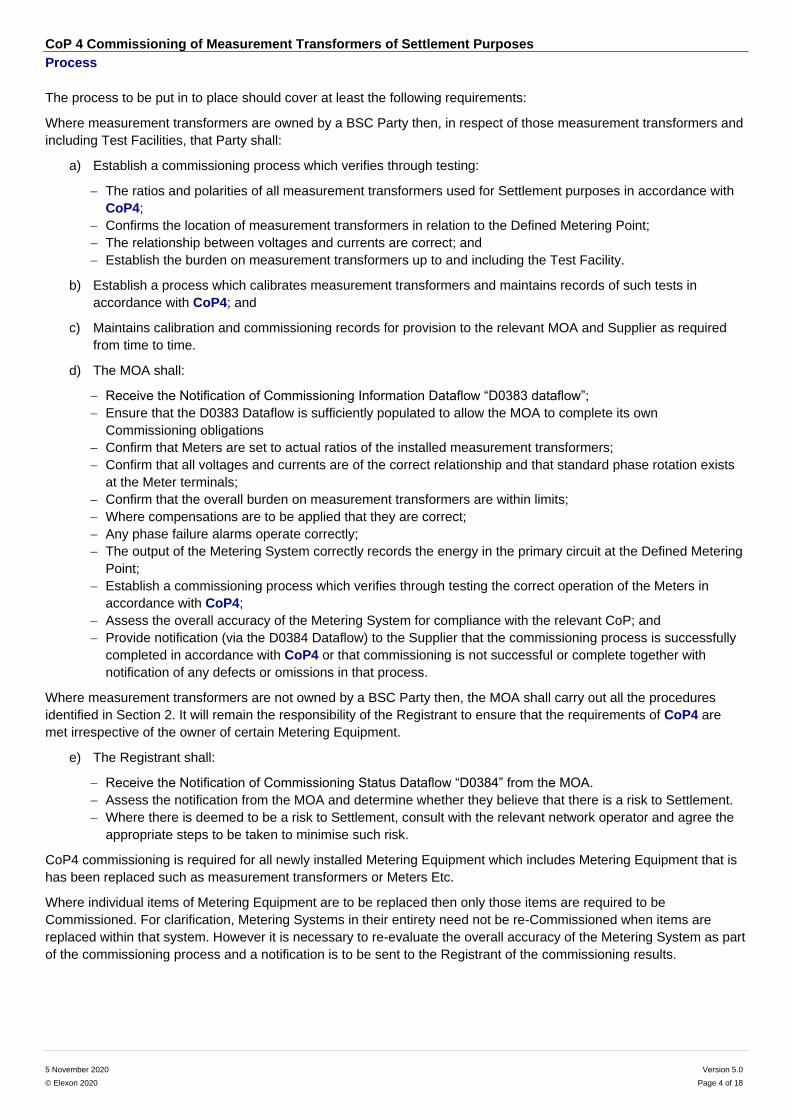
Process
The process to be put in to place should cover at least the following requirements:
Where measurement transformers are owned by a BSC Party then, in respect of those measurement transformers and
including Test Facilities, that Party shall:
a) Establish a commissioning process which verifies through testing:
The ratios and polarities of all measurement transformers used for Settlement purposes in accordance with
CoP4;
Confirms the location of measurement transformers in relation to the Defined Metering Point;
The relationship between voltages and currents are correct; and
Establish the burden on measurement transformers up to and including the Test Facility.
b) Establish a process which calibrates measurement transformers and maintains records of such tests in
accordance with CoP4; and
c) Maintains calibration and commissioning records for provision to the relevant MOA and Supplier as required
from time to time.
d) The MOA shall:
Receive the Notification of Commissioning Information Dataflow “D0383 dataflow”;
Ensure that the D0383 Dataflow is sufficiently populated to allow the MOA to complete its own
Commissioning obligations
Confirm that Meters are set to actual ratios of the installed measurement transformers;
Confirm that all voltages and currents are of the correct relationship and that standard phase rotation exists
at the Meter terminals;
Confirm that the overall burden on measurement transformers are within limits;
Where compensations are to be applied that they are correct;
Any phase failure alarms operate correctly;
The output of the Metering System correctly records the energy in the primary circuit at the Defined Metering
Point;
Establish a commissioning process which verifies through testing the correct operation of the Meters in
accordance with CoP4;
Assess the overall accuracy of the Metering System for compliance with the relevant CoP; and
Provide notification (via the D0384 Dataflow) to the Supplier that the commissioning process is successfully
completed in accordance with CoP4 or that commissioning is not successful or complete together with
notification of any defects or omissions in that process.
Where measurement transformers are not owned by a BSC Party then, the MOA shall carry out all the procedures
identified in Section 2. It will remain the responsibility of the Registrant to ensure that the requirements of CoP4 are
met irrespective of the owner of certain Metering Equipment.
e) The Registrant shall:
Receive the Notification of Commissioning Status Dataflow “D0384” from the MOA.
Assess the notification from the MOA and determine whether they believe that there is a risk to Settlement.
Where there is deemed to be a risk to Settlement, consult with the relevant network operator and agree the
appropriate steps to be taken to minimise such risk.
CoP4 commissioning is required for all newly installed Metering Equipment which includes Metering Equipment that is
has been replaced such as measurement transformers or Meters Etc.
Where individual items of Metering Equipment are to be replaced then only those items are required to be
Commissioned. For clarification, Metering Systems in their entirety need not be re-Commissioned when items are
replaced within that system. However it is necessary to re-evaluate the overall accuracy of the Metering System as part
of the commissioning process and a notification is to be sent to the Registrant of the commissioning results.
CoP 4 Commissioning of Measurement Transformers of Settlement Purposes
5 November 2020 Version 5.0
© Elexon 2020 Page 5 of 18
Scenarios
The following non-exhaustive scenarios are provided for assistance in meeting the requirements of CoP4:
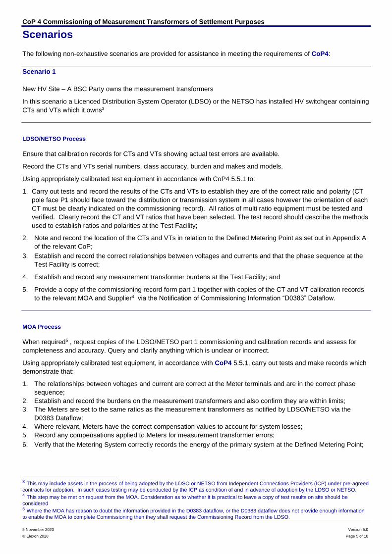
Scenario 1
New HV Site – A BSC Party owns the measurement transformers
In this scenario a Licenced Distribution System Operator (LDSO) or the NETSO has installed HV switchgear containing
CTs and VTs which it owns3
LDSO/NETSO Process
Ensure that calibration records for CTs and VTs showing actual test errors are available.
Record the CTs and VTs serial numbers, class accuracy, burden and makes and models.
Using appropriately calibrated test equipment in accordance with CoP4 5.5.1 to:
1. Carry out tests and record the results of the CTs and VTs to establish they are of the correct ratio and polarity (CT
pole face P1 should face toward the distribution or transmission system in all cases however the orientation of each
CT must be clearly indicated on the commissioning record). All ratios of multi ratio equipment must be tested and
verified. Clearly record the CT and VT ratios that have been selected. The test record should describe the methods
used to establish ratios and polarities at the Test Facility;
2. Note and record the location of the CTs and VTs in relation to the Defined Metering Point as set out in Appendix A
of the relevant CoP;
3. Establish and record the correct relationships between voltages and currents and that the phase sequence at the
Test Facility is correct;
4. Establish and record any measurement transformer burdens at the Test Facility; and
5. Provide a copy of the commissioning record form part 1 together with copies of the CT and VT calibration records
to the relevant MOA and Supplier4 via the Notification of Commissioning Information “D0383” Dataflow.
MOA Process
When required5 , request copies of the LDSO/NETSO part 1 commissioning and calibration records and assess for
completeness and accuracy. Query and clarify anything which is unclear or incorrect.
Using appropriately calibrated test equipment, in accordance with CoP4 5.5.1, carry out tests and make records which
demonstrate that:
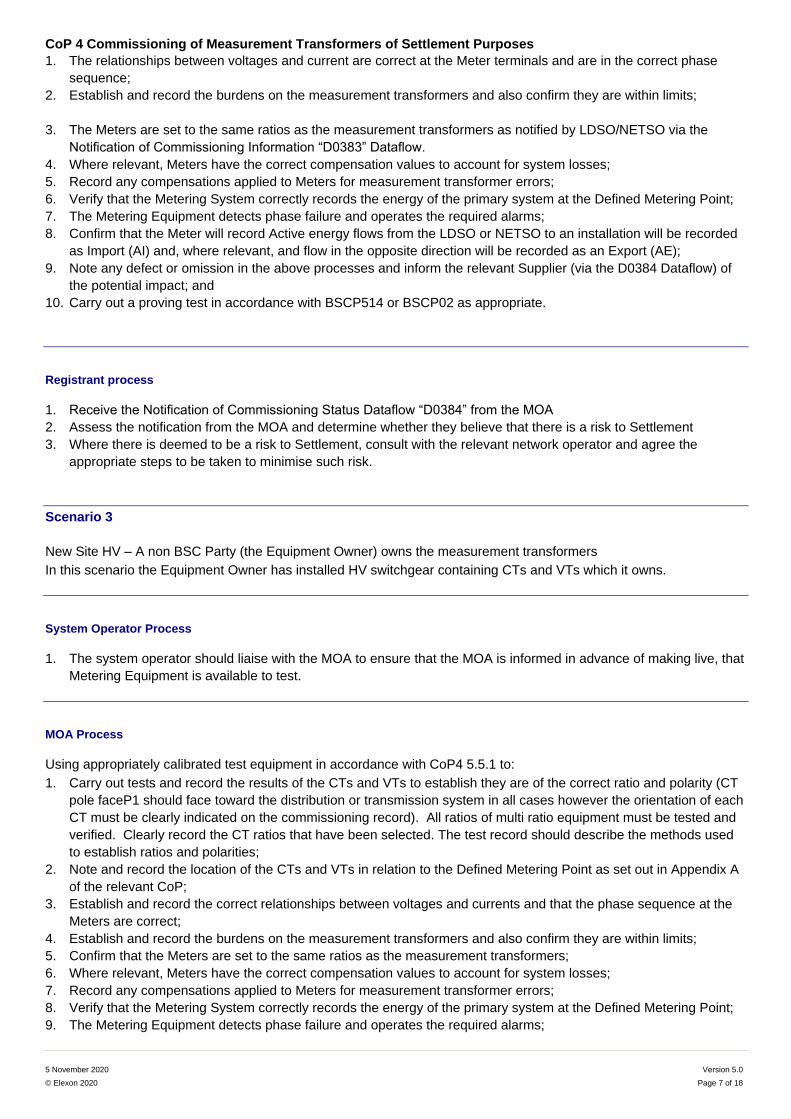
1. The relationships between voltages and current are correct at the Meter terminals and are in the correct phase
sequence;
2. Establish and record the burdens on the measurement transformers and also confirm they are within limits;
3. The Meters are set to the same ratios as the measurement transformers as notified by LDSO/NETSO via the
D0383 Dataflow;
4. Where relevant, Meters have the correct compensation values to account for system losses;
5. Record any compensations applied to Meters for measurement transformer errors;
6. Verify that the Metering System correctly records the energy of the primary system at the Defined Metering Point;
3 This may include assets in the process of being adopted by the LDSO or NETSO from Independent Connections Providers (ICP) under pre-agreed
contracts for adoption. In such cases testing may be conducted by the ICP as condition of and in advance of adoption by the LDSO or NETSO. 4 This step may be met on request from the MOA. Consideration as to whether it is practical to leave a copy of test results on site should be
considered 5 Where the MOA has reason to doubt the information provided in the D0383 dataflow, or the D0383 dataflow does not provide enough information
to enable the MOA to complete Commissioning then they shall request the Commissioning Record from the LDSO.
CoP 4 Commissioning of Measurement Transformers of Settlement Purposes
5 November 2020 Version 5.0
© Elexon 2020 Page 6 of 18
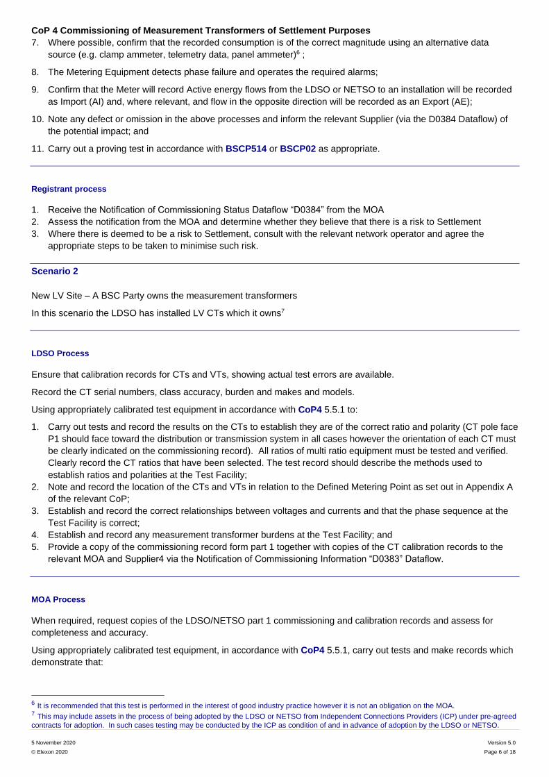
7. Where possible, confirm that the recorded consumption is of the correct magnitude using an alternative data
source (e.g. clamp ammeter, telemetry data, panel ammeter)6 ;
8. The Metering Equipment detects phase failure and operates the required alarms;
9. Confirm that the Meter will record Active energy flows from the LDSO or NETSO to an installation will be recorded
as Import (AI) and, where relevant, and flow in the opposite direction will be recorded as an Export (AE);
10. Note any defect or omission in the above processes and inform the relevant Supplier (via the D0384 Dataflow) of
the potential impact; and
11. Carry out a proving test in accordance with BSCP514 or BSCP02 as appropriate.
Registrant process
1. Receive the Notification of Commissioning Status Dataflow “D0384” from the MOA
2. Assess the notification from the MOA and determine whether they believe that there is a risk to Settlement
3. Where there is deemed to be a risk to Settlement, consult with the relevant network operator and agree the
appropriate steps to be taken to minimise such risk.
Scenario 2
New LV Site – A BSC Party owns the measurement transformers
In this scenario the LDSO has installed LV CTs which it owns7
LDSO Process
Ensure that calibration records for CTs and VTs, showing actual test errors are available.
Record the CT serial numbers, class accuracy, burden and makes and models.
Using appropriately calibrated test equipment in accordance with CoP4 5.5.1 to:
1. Carry out tests and record the results on the CTs to establish they are of the correct ratio and polarity (CT pole face
P1 should face toward the distribution or transmission system in all cases however the orientation of each CT must
be clearly indicated on the commissioning record). All ratios of multi ratio equipment must be tested and verified.
Clearly record the CT ratios that have been selected. The test record should describe the methods used to
establish ratios and polarities at the Test Facility;
2. Note and record the location of the CTs and VTs in relation to the Defined Metering Point as set out in Appendix A
of the relevant CoP;
3. Establish and record the correct relationships between voltages and currents and that the phase sequence at the
Test Facility is correct;
4. Establish and record any measurement transformer burdens at the Test Facility; and
5. Provide a copy of the commissioning record form part 1 together with copies of the CT calibration records to the
relevant MOA and Supplier4 via the Notification of Commissioning Information “D0383” Dataflow.
MOA Process
When required, request copies of the LDSO/NETSO part 1 commissioning and calibration records and assess for
completeness and accuracy.
Using appropriately calibrated test equipment, in accordance with CoP4 5.5.1, carry out tests and make records which
demonstrate that:
6 It is recommended that this test is performed in the interest of good industry practice however it is not an obligation on the MOA. 7 This may include assets in the process of being adopted by the LDSO or NETSO from Independent Connections Providers (ICP) under pre-agreed
contracts for adoption. In such cases testing may be conducted by the ICP as condition of and in advance of adoption by the LDSO or NETSO.
CoP 4 Commissioning of Measurement Transformers of Settlement Purposes
5 November 2020 Version 5.0
© Elexon 2020 Page 7 of 18
1. The relationships between voltages and current are correct at the Meter terminals and are in the correct phase
sequence;
2. Establish and record the burdens on the measurement transformers and also confirm they are within limits;
3. The Meters are set to the same ratios as the measurement transformers as notified by LDSO/NETSO via the
Notification of Commissioning Information “D0383” Dataflow.
4. Where relevant, Meters have the correct compensation values to account for system losses;
5. Record any compensations applied to Meters for measurement transformer errors;
6. Verify that the Metering System correctly records the energy of the primary system at the Defined Metering Point;
7. The Metering Equipment detects phase failure and operates the required alarms;
8. Confirm that the Meter will record Active energy flows from the LDSO or NETSO to an installation will be recorded
as Import (AI) and, where relevant, and flow in the opposite direction will be recorded as an Export (AE);
9. Note any defect or omission in the above processes and inform the relevant Supplier (via the D0384 Dataflow) of
the potential impact; and
10. Carry out a proving test in accordance with BSCP514 or BSCP02 as appropriate.
Registrant process
1. Receive the Notification of Commissioning Status Dataflow “D0384” from the MOA
2. Assess the notification from the MOA and determine whether they believe that there is a risk to Settlement
3. Where there is deemed to be a risk to Settlement, consult with the relevant network operator and agree the
appropriate steps to be taken to minimise such risk.
Scenario 3
New Site HV – A non BSC Party (the Equipment Owner) owns the measurement transformers
In this scenario the Equipment Owner has installed HV switchgear containing CTs and VTs which it owns.
System Operator Process
1. The system operator should liaise with the MOA to ensure that the MOA is informed in advance of making live, that
Metering Equipment is available to test.
MOA Process
Using appropriately calibrated test equipment in accordance with CoP4 5.5.1 to:
1. Carry out tests and record the results of the CTs and VTs to establish they are of the correct ratio and polarity (CT
pole faceP1 should face toward the distribution or transmission system in all cases however the orientation of each
CT must be clearly indicated on the commissioning record). All ratios of multi ratio equipment must be tested and
verified. Clearly record the CT ratios that have been selected. The test record should describe the methods used
to establish ratios and polarities;
2. Note and record the location of the CTs and VTs in relation to the Defined Metering Point as set out in Appendix A
of the relevant CoP;
3. Establish and record the correct relationships between voltages and currents and that the phase sequence at the
Meters are correct;
4. Establish and record the burdens on the measurement transformers and also confirm they are within limits;
5. Confirm that the Meters are set to the same ratios as the measurement transformers;
6. Where relevant, Meters have the correct compensation values to account for system losses;
7. Record any compensations applied to Meters for measurement transformer errors;
8. Verify that the Metering System correctly records the energy of the primary system at the Defined Metering Point;
9. The Metering Equipment detects phase failure and operates the required alarms;
CoP 4 Commissioning of Measurement Transformers of Settlement Purposes
5 November 2020 Version 5.0
© Elexon 2020 Page 8 of 18
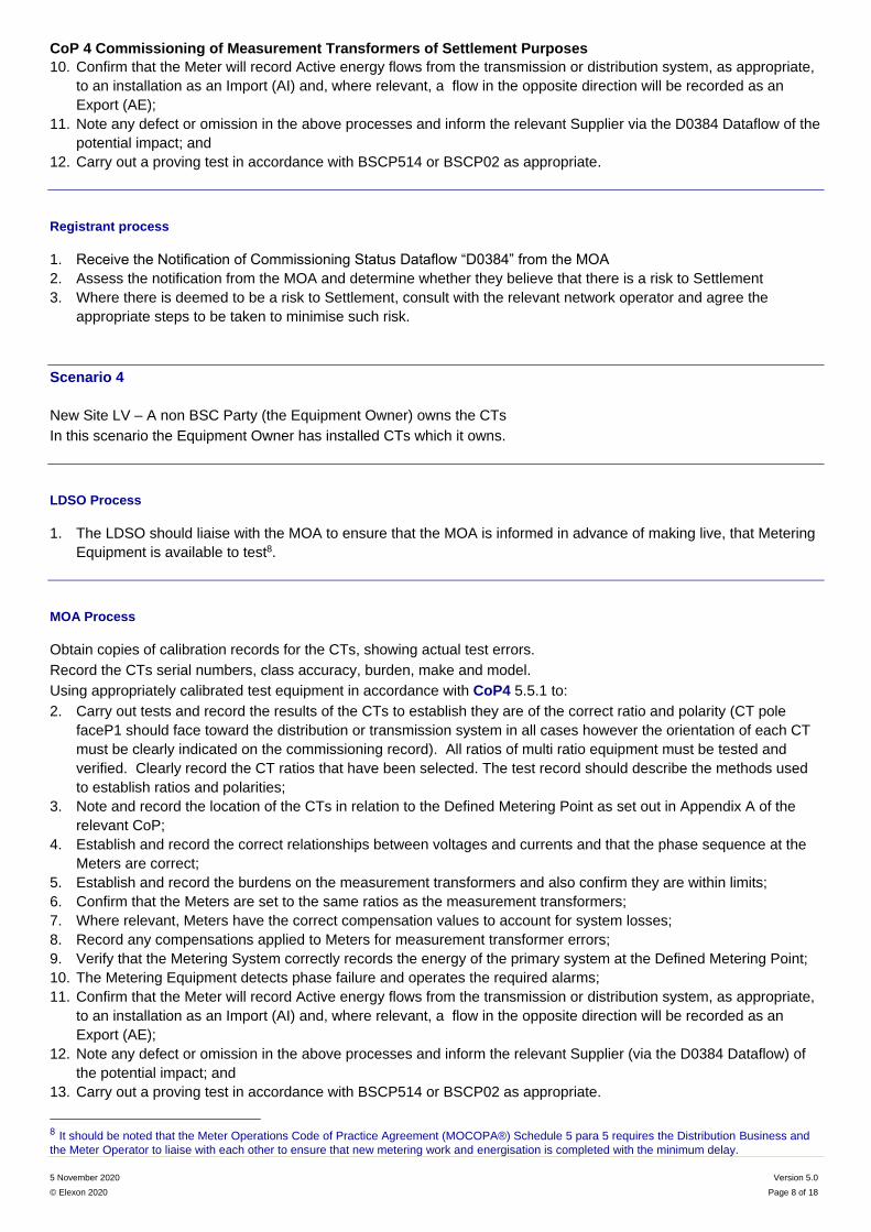
10. Confirm that the Meter will record Active energy flows from the transmission or distribution system, as appropriate,
to an installation as an Import (AI) and, where relevant, a flow in the opposite direction will be recorded as an
Export (AE);
11. Note any defect or omission in the above processes and inform the relevant Supplier via the D0384 Dataflow of the
potential impact; and
12. Carry out a proving test in accordance with BSCP514 or BSCP02 as appropriate.
Registrant process
1. Receive the Notification of Commissioning Status Dataflow “D0384” from the MOA
2. Assess the notification from the MOA and determine whether they believe that there is a risk to Settlement
3. Where there is deemed to be a risk to Settlement, consult with the relevant network operator and agree the
appropriate steps to be taken to minimise such risk.
Scenario 4
New Site LV – A non BSC Party (the Equipment Owner) owns the CTs
In this scenario the Equipment Owner has installed CTs which it owns.
LDSO Process
1. The LDSO should liaise with the MOA to ensure that the MOA is informed in advance of making live, that Metering
Equipment is available to test8.
MOA Process
Obtain copies of calibration records for the CTs, showing actual test errors.
Record the CTs serial numbers, class accuracy, burden, make and model.
Using appropriately calibrated test equipment in accordance with CoP4 5.5.1 to:
2. Carry out tests and record the results of the CTs to establish they are of the correct ratio and polarity (CT pole
faceP1 should face toward the distribution or transmission system in all cases however the orientation of each CT
must be clearly indicated on the commissioning record). All ratios of multi ratio equipment must be tested and
verified. Clearly record the CT ratios that have been selected. The test record should describe the methods used
to establish ratios and polarities;
3. Note and record the location of the CTs in relation to the Defined Metering Point as set out in Appendix A of the
relevant CoP;
4. Establish and record the correct relationships between voltages and currents and that the phase sequence at the
Meters are correct;
5. Establish and record the burdens on the measurement transformers and also confirm they are within limits;
6. Confirm that the Meters are set to the same ratios as the measurement transformers;
7. Where relevant, Meters have the correct compensation values to account for system losses;
8. Record any compensations applied to Meters for measurement transformer errors;
9. Verify that the Metering System correctly records the energy of the primary system at the Defined Metering Point;
10. The Metering Equipment detects phase failure and operates the required alarms;
11. Confirm that the Meter will record Active energy flows from the transmission or distribution system, as appropriate,
to an installation as an Import (AI) and, where relevant, a flow in the opposite direction will be recorded as an
Export (AE);
12. Note any defect or omission in the above processes and inform the relevant Supplier (via the D0384 Dataflow) of
the potential impact; and
13. Carry out a proving test in accordance with BSCP514 or BSCP02 as appropriate.
8 It should be noted that the Meter Operations Code of Practice Agreement (MOCOPA®) Schedule 5 para 5 requires the Distribution Business and
the Meter Operator to liaise with each other to ensure that new metering work and energisation is completed with the minimum delay.
CoP 4 Commissioning of Measurement Transformers of Settlement Purposes
5 November 2020 Version 5.0
© Elexon 2020 Page 9 of 18
Registrant process
1. Receive the Notification of Commissioning Status Dataflow “D0384” from the MOA
2. Assess the notification from the MOA and determine whether they believe that there is a risk to Settlement
3. Where there is deemed to be a risk to Settlement, consult with the relevant network operator and agree the
appropriate steps to be taken to minimise such risk.
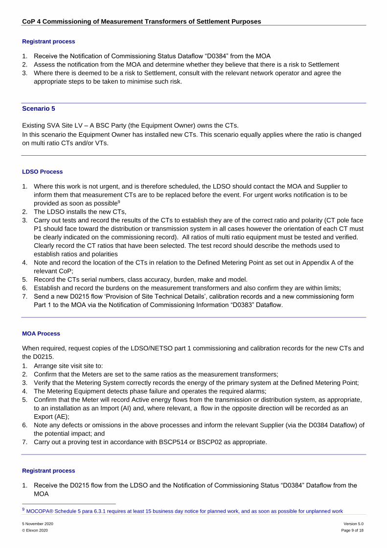
Scenario 5
Existing SVA Site LV – A BSC Party (the Equipment Owner) owns the CTs.
In this scenario the Equipment Owner has installed new CTs. This scenario equally applies where the ratio is changed
on multi ratio CTs and/or VTs.
LDSO Process
1. Where this work is not urgent, and is therefore scheduled, the LDSO should contact the MOA and Supplier to
inform them that measurement CTs are to be replaced before the event. For urgent works notification is to be
provided as soon as possible9
2. The LDSO installs the new CTs,
3. Carry out tests and record the results of the CTs to establish they are of the correct ratio and polarity (CT pole face
P1 should face toward the distribution or transmission system in all cases however the orientation of each CT must
be clearly indicated on the commissioning record). All ratios of multi ratio equipment must be tested and verified.
Clearly record the CT ratios that have been selected. The test record should describe the methods used to
establish ratios and polarities
4. Note and record the location of the CTs in relation to the Defined Metering Point as set out in Appendix A of the
relevant CoP;
5. Record the CTs serial numbers, class accuracy, burden, make and model.
6. Establish and record the burdens on the measurement transformers and also confirm they are within limits;
7. Send a new D0215 flow ‘Provision of Site Technical Details’, calibration records and a new commissioning form
Part 1 to the MOA via the Notification of Commissioning Information “D0383” Dataflow.
MOA Process
When required, request copies of the LDSO/NETSO part 1 commissioning and calibration records for the new CTs and
the D0215.
1. Arrange site visit site to:
2. Confirm that the Meters are set to the same ratios as the measurement transformers;
3. Verify that the Metering System correctly records the energy of the primary system at the Defined Metering Point;
4. The Metering Equipment detects phase failure and operates the required alarms;
5. Confirm that the Meter will record Active energy flows from the transmission or distribution system, as appropriate,
to an installation as an Import (AI) and, where relevant, a flow in the opposite direction will be recorded as an
Export (AE);
6. Note any defects or omissions in the above processes and inform the relevant Supplier (via the D0384 Dataflow) of
the potential impact; and
7. Carry out a proving test in accordance with BSCP514 or BSCP02 as appropriate.
Registrant process
1. Receive the D0215 flow from the LDSO and the Notification of Commissioning Status “D0384” Dataflow from the
MOA
9 MOCOPA® Schedule 5 para 6.3.1 requires at least 15 business day notice for planned work, and as soon as possible for unplanned work
CoP 4 Commissioning of Measurement Transformers of Settlement Purposes
5 November 2020 Version 5.0
© Elexon 2020 Page 10 of 18
2. Assess the notification from the MOA and determine whether they believe that there is a risk to Settlement
3. Where there is deemed to be a risk to Settlement, consult with the relevant network operator and agree the
appropriate steps to be taken to minimise such risk.
Scenario 6
Existing Site LV – A BSC Party (the Equipment Owner) owns the CTs
In this scenario the Meter Operator Agent replaces a Meter and there are no commissioning records for the CTs.
MOA Process
1. If not already received request a D0215 from the LDSO;
2. MOA visits site to replace a Meter;
3. Ensure that the CT ratio of the D0215 matches that of the CT labels – Note any discrepancies;
4. Based on the CT labels, if visible, confirm that the Meters are set to the same ratios as the measurement
transformers;
5. Verify that the Metering System correctly records the energy of the primary system at the Defined Metering Point;
6. The Metering Equipment detects phase failure and operates the required alarms;
7. Confirm that the Meter will record Active energy flows from the transmission or distribution system, as appropriate,
to an installation as an Import (AI) and, where relevant, a flow in the opposite direction will be recorded as an
Export (AE);
8. Note any defects or omissions in the above processes and inform the relevant Supplier (via the D0384 Dataflow) of
the potential impact; and
9. Carry out a proving test in accordance with BSCP514 or BSCP02 as appropriate.
Registrant process
1. Assess the Notification of Commissioning Status “D0384” Dataflow from the MOA and determine whether they
believe that there is a risk to Settlement
2. Where there is deemed to be a risk to Settlement, consult with the relevant network operator and agree the
appropriate steps to be taken to minimise such risk.
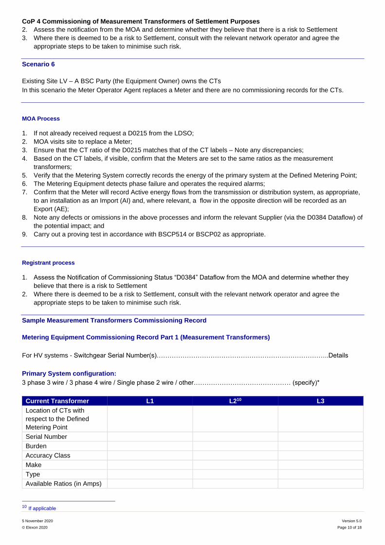
Sample Measurement Transformers Commissioning Record
Metering Equipment Commissioning Record Part 1 (Measurement Transformers)
For HV systems - Switchgear Serial Number(s)……………………………………………………………………..Details
Primary System configuration:
3 phase 3 wire / 3 phase 4 wire / Single phase 2 wire / other……………………………………… (specify)*
Current Transformer L1 L210 L3
Location of CTs with
respect to the Defined
Metering Point
Serial Number
Burden
Accuracy Class
Make
Type
Available Ratios (in Amps)
10 If applicable
CoP 4 Commissioning of Measurement Transformers of Settlement Purposes
5 November 2020 Version 5.0
© Elexon 2020 Page 11 of 18
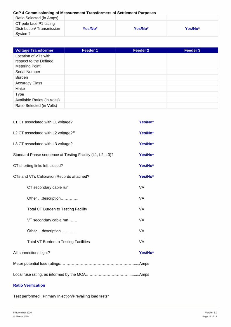
Ratio Selected (in Amps)
CT pole face P1 facing
Distribution/ Transmission
System?
Yes/No* Yes/No* Yes/No*
Voltage Transformer Feeder 1 Feeder 2 Feeder 3
Location of VTs with
respect to the Defined
Metering Point
Serial Number
Burden
Accuracy Class
Make
Type
Available Ratios (in Volts)
Ratio Selected (in Volts)
L1 CT associated with L1 voltage? Yes/No*
L2 CT associated with L2 voltage?10 Yes/No*
L3 CT associated with L3 voltage? Yes/No*
Standard Phase sequence at Testing Facility (L1, L2, L3)? Yes/No*
CT shorting links left closed? Yes/No*
CTs and VTs Calibration Records attached? Yes/No*
CT secondary cable run VA
Other …description………….. VA
Total CT Burden to Testing Facility VA
VT secondary cable run……. VA
Other …description…………. VA
Total VT Burden to Testing Facilities VA
All connections tight? Yes/No*
Meter potential fuse ratings………………………………………………….....Amps
Local fuse rating, as informed by the MOA……………………………..........Amps
Ratio Verification
Test performed: Primary Injection/Prevailing load tests*
CoP 4 Commissioning of Measurement Transformers of Settlement Purposes
5 November 2020 Version 5.0
© Elexon 2020 Page 12 of 18
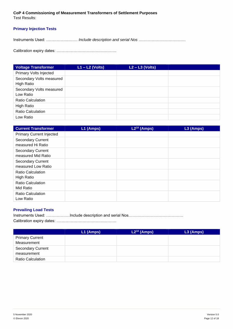
Test Results:
Primary Injection Tests
Instruments Used: …………………… Include description and serial Nos ………………………………
Calibration expiry dates: ……………………………………….
Voltage Transformer L1 – L2 (Volts) L2 – L3 (Volts)
Primary Volts Injected
Secondary Volts measured
High Ratio
Secondary Volts measured
Low Ratio
Ratio Calculation
High Ratio
Ratio Calculation
Low Ratio
Current Transformer L1 (Amps) L210 (Amps) L3 (Amps)
Primary Current Injected
Secondary Current
measured Hi Ratio
Secondary Current
measured Mid Ratio
Secondary Current
measured Low Ratio
Ratio Calculation
High Ratio
Ratio Calculation
Mid Ratio
Ratio Calculation
Low Ratio
Prevailing Load Tests
Instruments Used: ………………Include description and serial Nos……………………………………
Calibration expiry dates: ……………………………………….
L1 (Amps) L210 (Amps) L3 (Amps)
Primary Current
Measurement
Secondary Current
measurement
Ratio Calculation
CoP 4 Commissioning of Measurement Transformers of Settlement Purposes
5 November 2020 Version 5.0
© Elexon 2020 Page 13 of 18
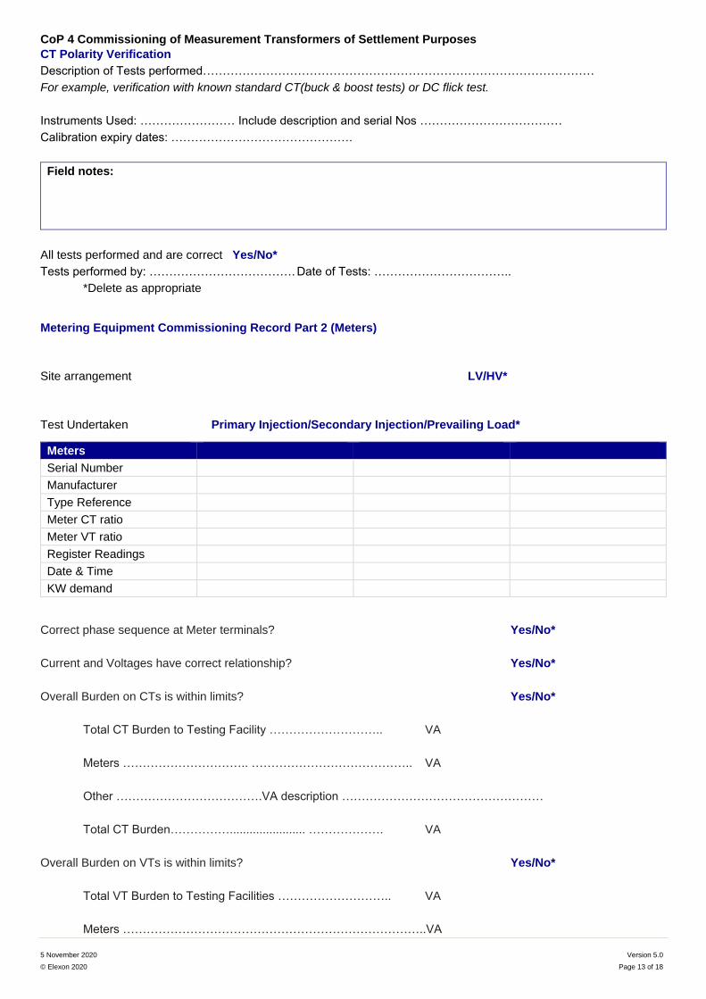
CT Polarity Verification
Description of Tests performed………………………………………………………………………………………
For example, verification with known standard CT(buck & boost tests) or DC flick test.
Instruments Used: …………………… Include description and serial Nos ………………………………
Calibration expiry dates: ……………………………………….
Field notes:
All tests performed and are correct Yes/No*
Tests performed by: ………………………………. Date of Tests: ……………………………..
*Delete as appropriate
Metering Equipment Commissioning Record Part 2 (Meters)
Site arrangement LV/HV*
Test Undertaken Primary Injection/Secondary Injection/Prevailing Load*
Meters
Serial Number
Manufacturer
Type Reference
Meter CT ratio
Meter VT ratio
Register Readings
Date & Time
KW demand
Correct phase sequence at Meter terminals? Yes/No*
Current and Voltages have correct relationship? Yes/No*
Overall Burden on CTs is within limits? Yes/No*
Total CT Burden to Testing Facility ……………………….. VA
Meters ………………………….. ………………………………….. VA
Other ……………………………….VA description ……………………………………………
Total CT Burden……………....................... ………………. VA
Overall Burden on VTs is within limits? Yes/No*
Total VT Burden to Testing Facilities ……………………….. VA
Meters …………………………………………………………………..VA
CoP 4 Commissioning of Measurement Transformers of Settlement Purposes
5 November 2020 Version 5.0
© Elexon 2020 Page 14 of 18
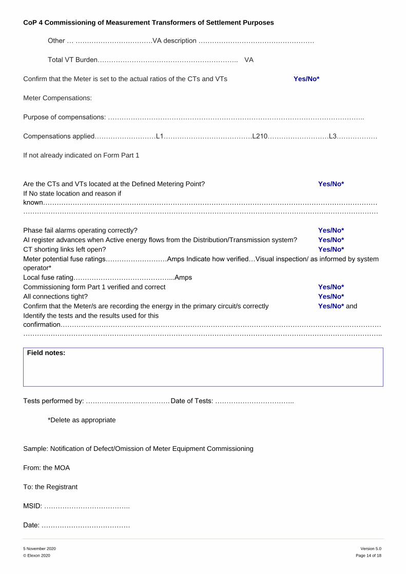
Other … …………………………….VA description ……………………………………………
Total VT Burden…………………………………………………….. VA
Confirm that the Meter is set to the actual ratios of the CTs and VTs Yes/No*
Meter Compensations:
Purpose of compensations: …………………………………………………………………………………………………..
Compensations applied………………………L1…………………………………L210………………………L3………………
If not already indicated on Form Part 1
Are the CTs and VTs located at the Defined Metering Point? Yes/No*
If No state location and reason if
known…………………………………………………………………………………………………………………………………
…………………………………………………………………………………………………………………………………………
Phase fail alarms operating correctly? Yes/No*
AI register advances when Active energy flows from the Distribution/Transmission system? Yes/No*
CT shorting links left open? Yes/No*
Meter potential fuse ratings………………………Amps Indicate how verified…Visual inspection/ as informed by system
operator*
Local fuse rating……………………………………...Amps
Commissioning form Part 1 verified and correct Yes/No*
All connections tight? Yes/No*
Confirm that the Meter/s are recording the energy in the primary circuit/s correctly Yes/No* and
Identify the tests and the results used for this
confirmation……………………………………………………………………………………………………………………………
…………………………………………………………………………………………………………………………………………..
Field notes:
Tests performed by: ………………………………. Date of Tests: ……………………………..
*Delete as appropriate
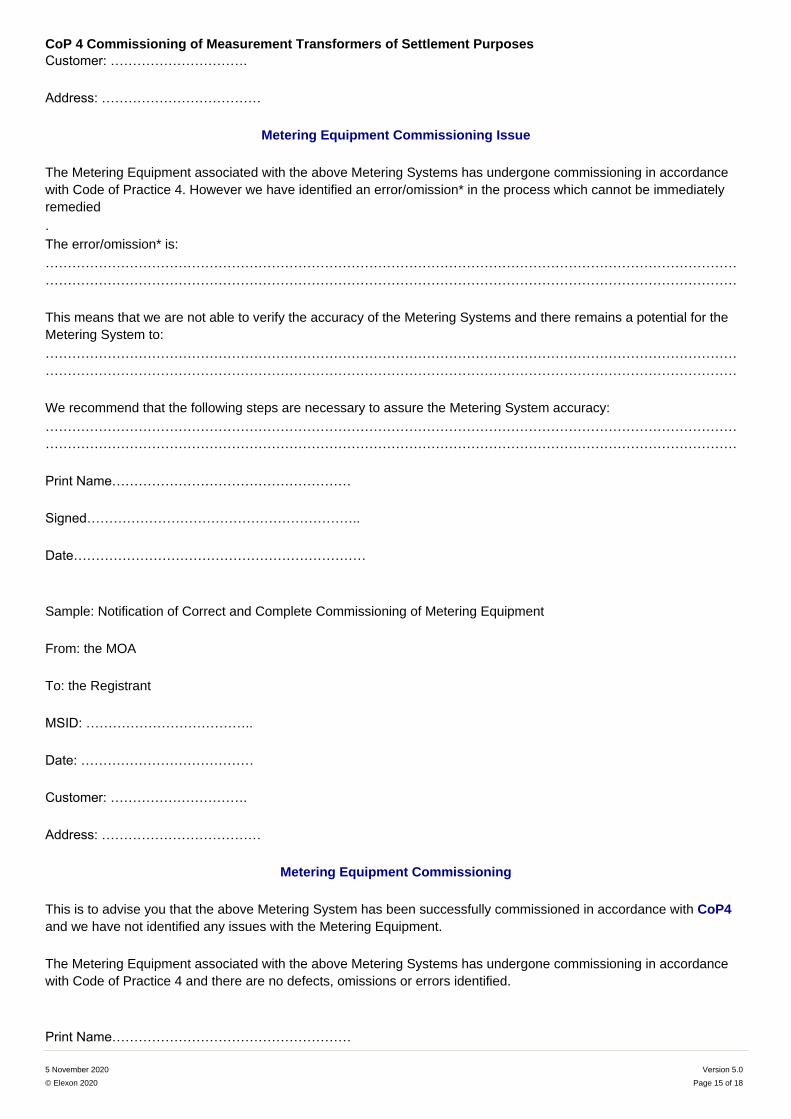
Sample: Notification of Defect/Omission of Meter Equipment Commissioning
From: the MOA
To: the Registrant
MSID: ………………………………..
Date: …………………………………
CoP 4 Commissioning of Measurement Transformers of Settlement Purposes
5 November 2020 Version 5.0
© Elexon 2020 Page 15 of 18
Customer: ………………………….
Address: ………………………………
Metering Equipment Commissioning Issue
The Metering Equipment associated with the above Metering Systems has undergone commissioning in accordance
with Code of Practice 4. However we have identified an error/omission* in the process which cannot be immediately
remedied
.
The error/omission* is:
…………………………………………………………………………………………………………………………………………
…………………………………………………………………………………………………………………………………………
This means that we are not able to verify the accuracy of the Metering Systems and there remains a potential for the
Metering System to:
…………………………………………………………………………………………………………………………………………
…………………………………………………………………………………………………………………………………………
We recommend that the following steps are necessary to assure the Metering System accuracy:
…………………………………………………………………………………………………………………………………………
…………………………………………………………………………………………………………………………………………
Print Name………………………………………………
Signed……………………………………………………..
Date…………………………………………………………
Sample: Notification of Correct and Complete Commissioning of Metering Equipment
From: the MOA
To: the Registrant
MSID: ………………………………..
Date: …………………………………
Customer: ………………………….
Address: ………………………………
Metering Equipment Commissioning
This is to advise you that the above Metering System has been successfully commissioned in accordance with CoP4
and we have not identified any issues with the Metering Equipment.
The Metering Equipment associated with the above Metering Systems has undergone commissioning in accordance
with Code of Practice 4 and there are no defects, omissions or errors identified.
Print Name………………………………………………
CoP 4 Commissioning of Measurement Transformers of Settlement Purposes
5 November 2020 Version 5.0
© Elexon 2020 Page 16 of 18
Signed……………………………………………………..
Date…………………………………………………………
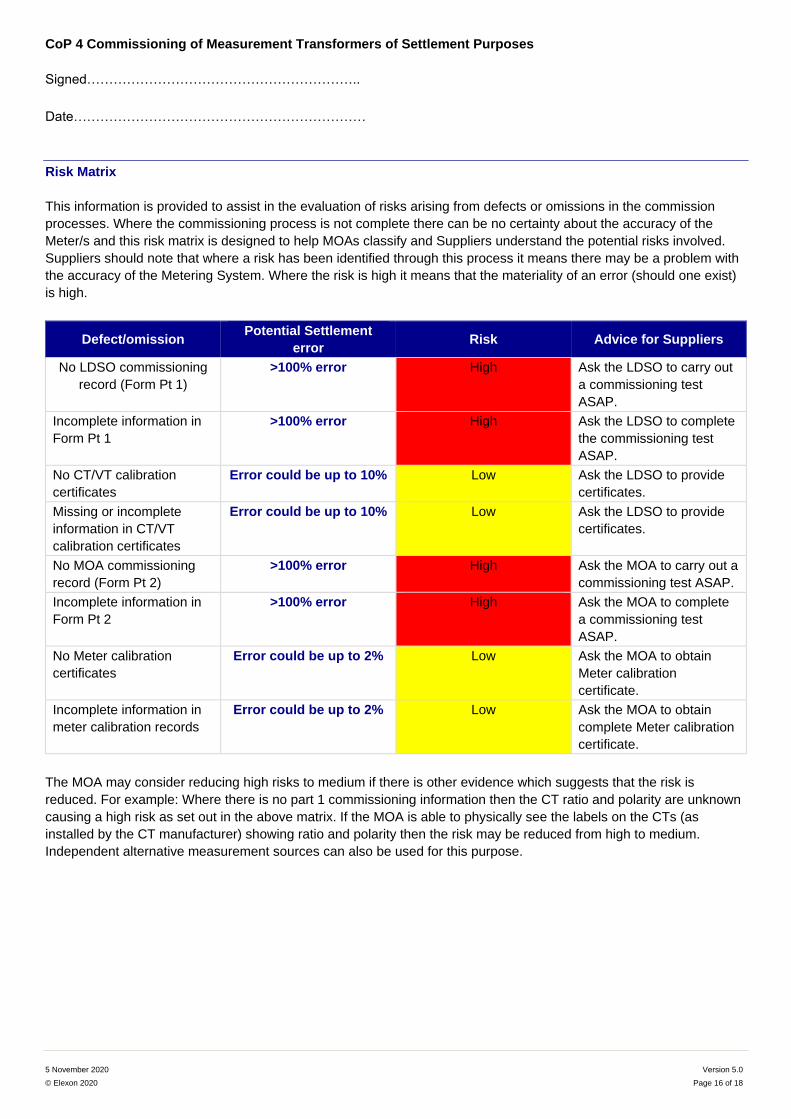
Risk Matrix
This information is provided to assist in the evaluation of risks arising from defects or omissions in the commission
processes. Where the commissioning process is not complete there can be no certainty about the accuracy of the
Meter/s and this risk matrix is designed to help MOAs classify and Suppliers understand the potential risks involved.
Suppliers should note that where a risk has been identified through this process it means there may be a problem with
the accuracy of the Metering System. Where the risk is high it means that the materiality of an error (should one exist)
is high.
Defect/omission Potential Settlement
error Risk Advice for Suppliers
No LDSO commissioning
record (Form Pt 1)
>100% error High Ask the LDSO to carry out
a commissioning test
ASAP.
Incomplete information in
Form Pt 1
>100% error High Ask the LDSO to complete
the commissioning test
ASAP.
No CT/VT calibration
certificates
Error could be up to 10% Low Ask the LDSO to provide
certificates.
Missing or incomplete
information in CT/VT
calibration certificates
Error could be up to 10% Low Ask the LDSO to provide
certificates.
No MOA commissioning
record (Form Pt 2)
>100% error High Ask the MOA to carry out a
commissioning test ASAP.
Incomplete information in
Form Pt 2
>100% error High Ask the MOA to complete
a commissioning test
ASAP.
No Meter calibration
certificates
Error could be up to 2% Low Ask the MOA to obtain
Meter calibration
certificate.
Incomplete information in
meter calibration records
Error could be up to 2% Low Ask the MOA to obtain
complete Meter calibration
certificate.
The MOA may consider reducing high risks to medium if there is other evidence which suggests that the risk is
reduced. For example: Where there is no part 1 commissioning information then the CT ratio and polarity are unknown
causing a high risk as set out in the above matrix. If the MOA is able to physically see the labels on the CTs (as
installed by the CT manufacturer) showing ratio and polarity then the risk may be reduced from high to medium.
Independent alternative measurement sources can also be used for this purpose.
CoP 4 Commissioning of Measurement Transformers of Settlement Purposes
5 November 2020 Version 5.0
© Elexon 2020 Page 17 of 18
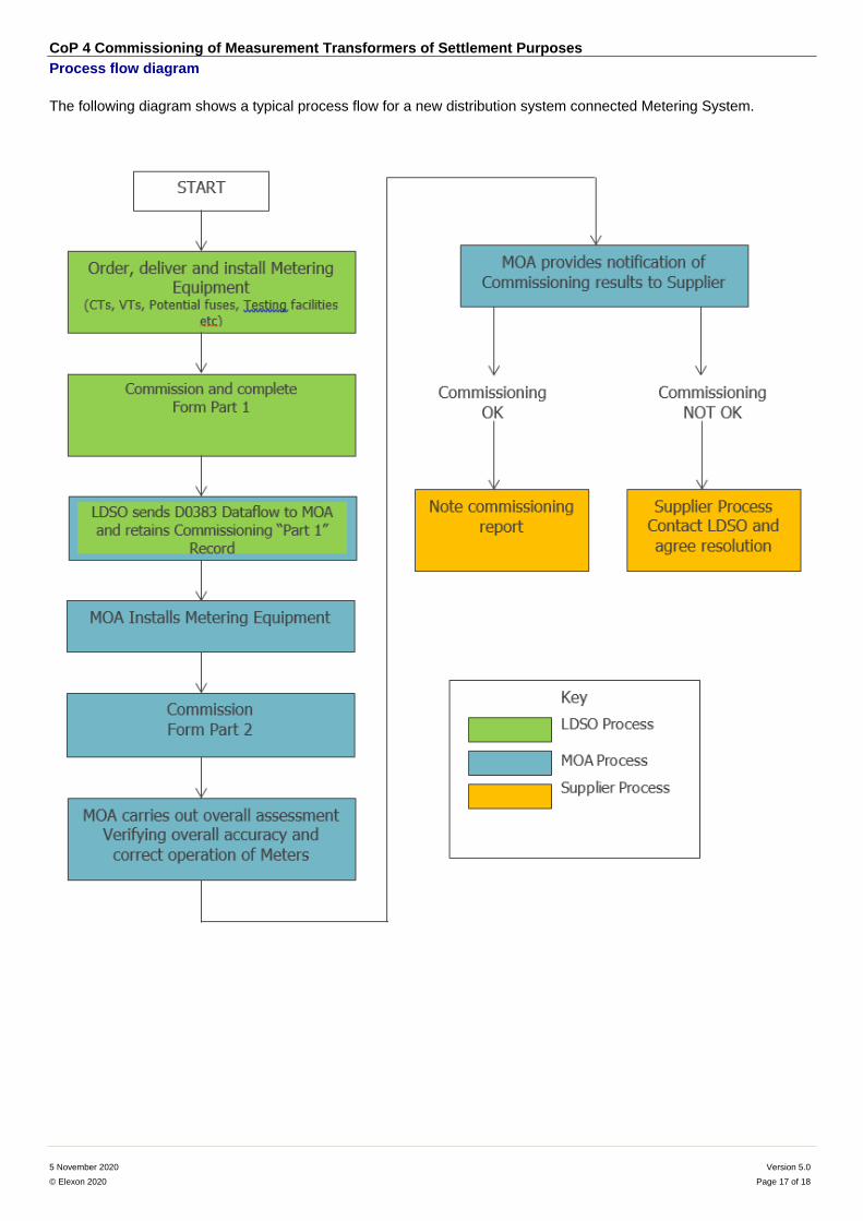
Process flow diagram
The following diagram shows a typical process flow for a new distribution system connected Metering System.
CoP 4 Commissioning of Measurement Transformers of Settlement Purposes
5 November 2020 Version 5.0
© Elexon 2020 Page 18 of 18
Further Information?
Useful Links
BSCP02
BSCP514
Code of Practice 4
BSC Guidance Notes
Elexon Ltd
For more information please contact the BSC Service Desk or call 0370 010 6950.
Intellectual Property Rights, Copyright and Disclaimer
The copyright and other intellectual property rights in this document are vested in Elexon or appear with the consent
of the copyright owner. These materials are made available for you for the purposes of your participation in the
electricity industry. If you have an interest in the electricity industry, you may view, download, copy, distribute,
modify, transmit, publish, sell or create derivative works (in whatever format) from this document or in other cases
use for personal academic or other non-commercial purposes. All copyright and other proprietary notices contained
in the document must be retained on any copy you make.
All other rights of the copyright owner not expressly dealt with above are reserved.
No representation, warranty or guarantee is made that the information in this document is accurate or complete.
While care is taken in the collection and provision of this information, Elexon Limited shall not be liable for any
errors, omissions, misstatements or mistakes in any information or damages resulting from the use of this
information or action taken in reliance on it.