Embed Size (px)
Citation preview
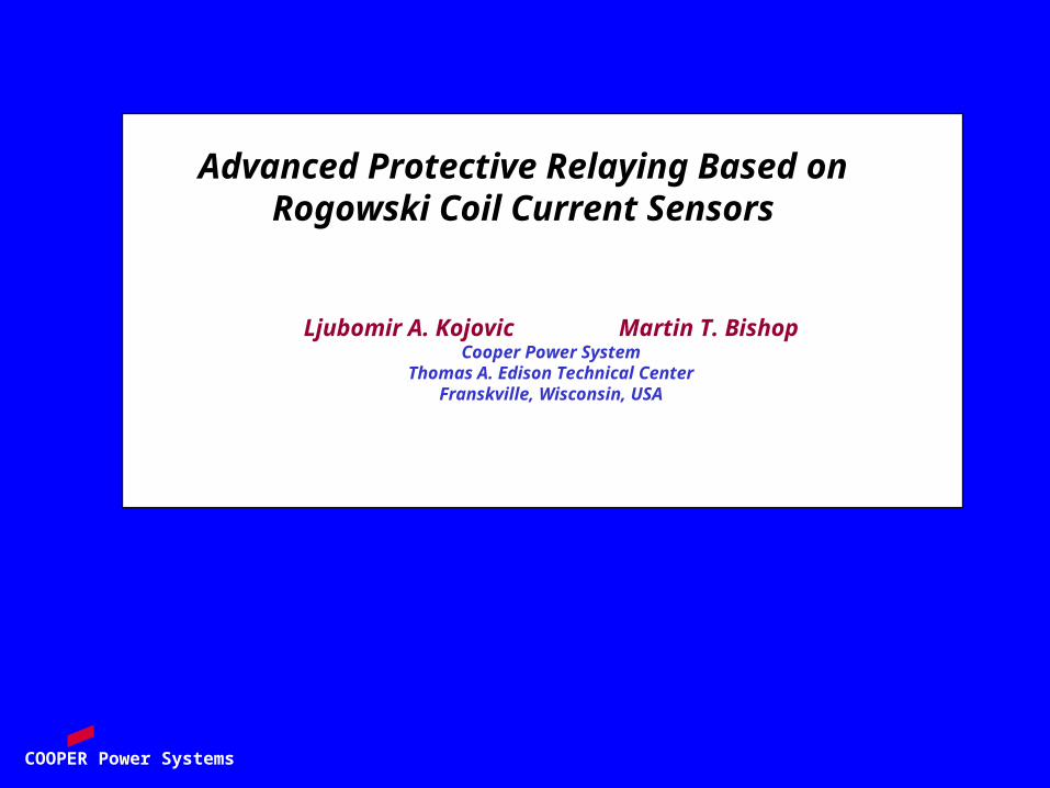
COOPER Power Systems
Advanced Protective Relaying Based on Rogowski Coil Current Sensors
Ljubomir A. Kojovic Martin T. BishopCooper Power System
Thomas A. Edison Technical CenterFranskville, Wisconsin, USA
COOPER Power Systems
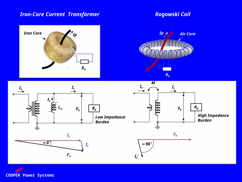
IP’
90
Iron-Core Current Transformer Rogowski Coil
IPIS
IE
M
RB
IP
VB
I’P
IS
IE 0
RBVB
IS
Low ImpedanceBurden
High ImpedanceBurden
VB
Lm
Ip Air Core
RB
Ip
RB
Iron Core
COOPER Power Systems
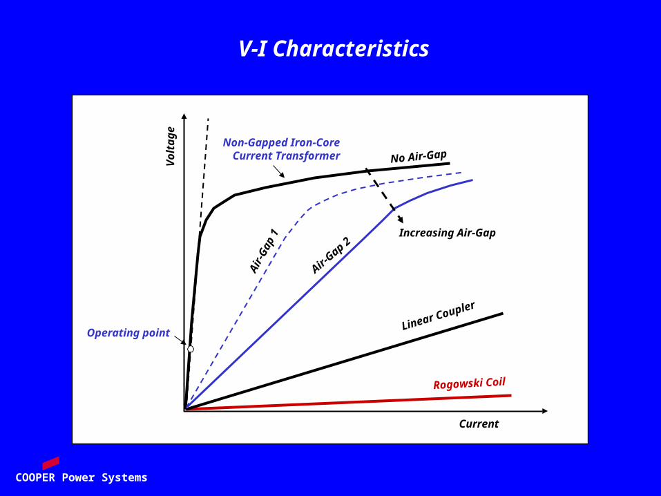
Vo
lta
ge
Current
Operating point
Non-Gapped Iron-Core Current Transformer
Rogowski Coil
Linear Coupler
Increasing Air-Gap
No Air-Gap
Air
-Gap
1
Air-Gap 2
V-I Characteristics
COOPER Power Systems
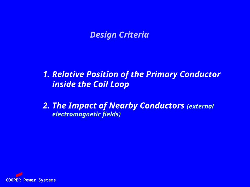
Design Criteria
1. Relative Position of the Primary Conductor inside the Coil Loop
2. The Impact of Nearby Conductors (external electromagnetic fields)
COOPER Power Systems
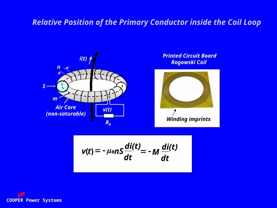
Printed Circuit Board Rogowski Coil
Winding imprints
dt
di(t)M
dt
di(t)nStv )( 0
Relative Position of the Primary Conductor inside the Coil Loop
S
n
i(t)
m
RB
Air Core(non-saturable)
v(t)

COOPER Power Systems
v(t)
PCB1 PCB2
PCB2 wound
in opposite direction
to PCB1
i(t)
External Electromagnetic Fields Curre
nt
Voltage
COOPER Power Systems
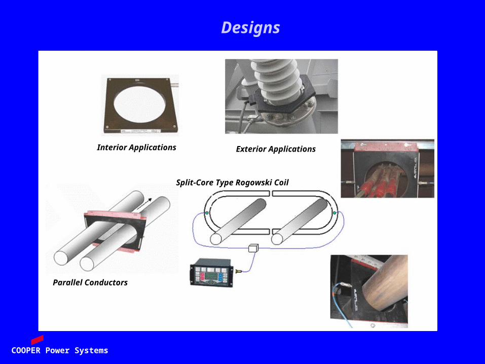
Interior Applications Exterior Applications
Parallel Conductors
Split-Core Type Rogowski Coil
Designs
COOPER Power Systems
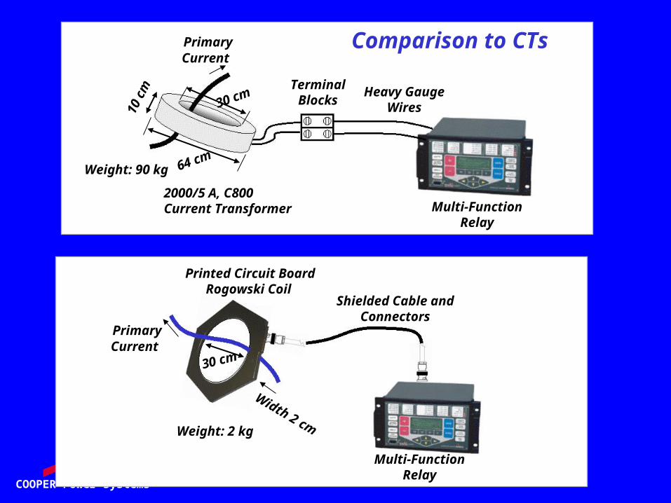
Heavy Gauge Wires
Multi-Function Relay
PrimaryCurrent
2000/5 A, C800Current Transformer
10 c
m Terminal Blocks
Weight: 90 kg64 cm
30 cm
Printed Circuit Board Rogowski Coil
Multi-Function Relay
PrimaryCurrent
Width 2 cmWeight: 2 kg
30 cm
Shielded Cable and Connectors
Comparison to CTs
COOPER Power Systems
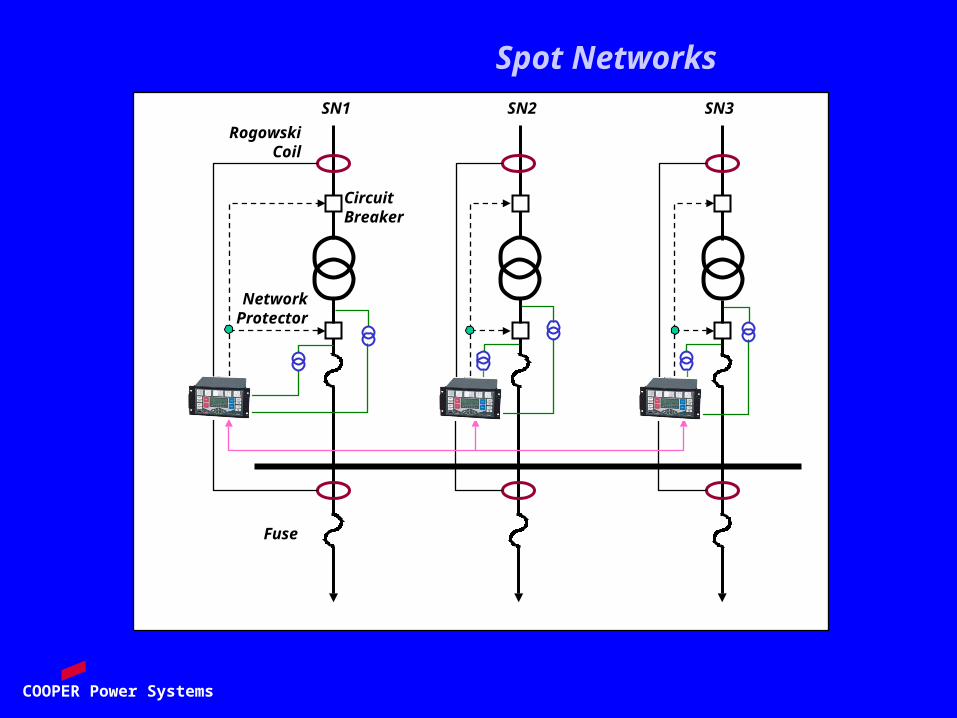
SN1 SN2 SN3
RogowskiCoil
Fuse
CircuitBreaker
NetworkProtector
Spot Networks

COOPER Power Systems
R
Bus
Network 2
Network 1
G
Load
Zone 1
Zone 2
Zone 3
Zone 4
Zone 5
Integrated Relay Protection Solutions
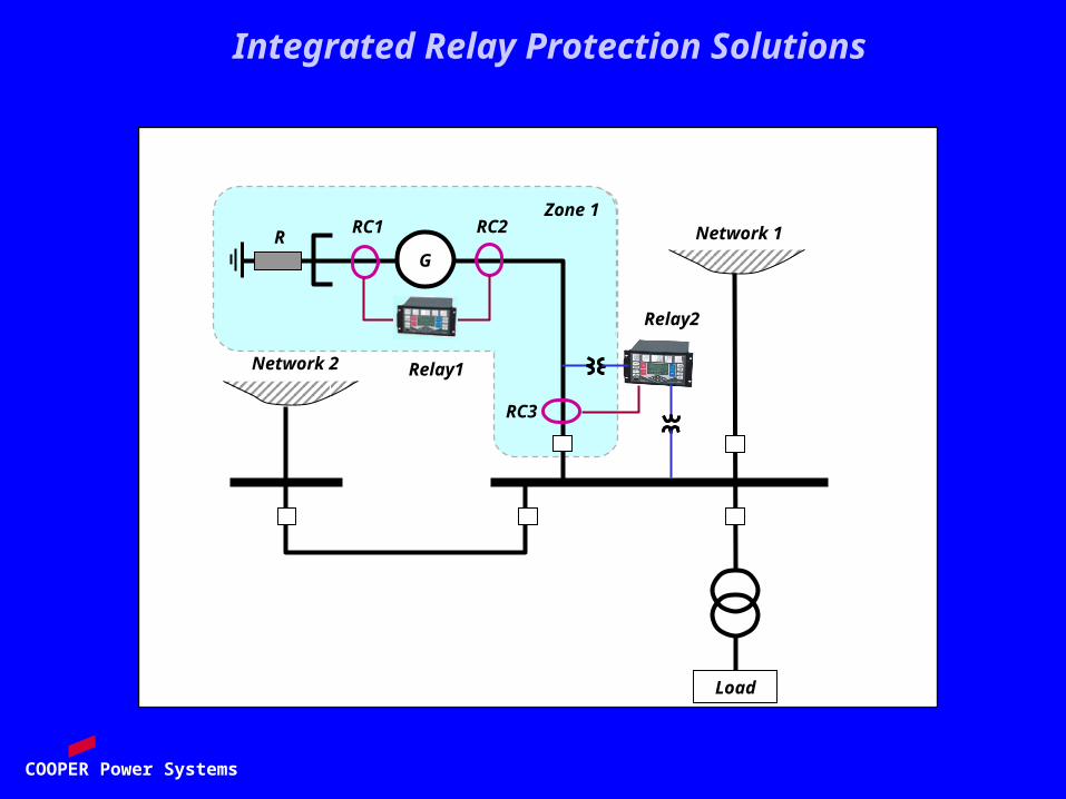
COOPER Power Systems
R
Network 2
Network 1
G
Load
RC3
Zone 1RC1 RC2
Relay1
Relay2
Integrated Relay Protection Solutions

COOPER Power Systems
R
Network 2
Network 1
G
Load
RC1 RC2
Zone 2
Relay1 Relay2
Fiber OpticCable
EthernetSwitch
other IEDs
Integrated Relay Protection Solutions

COOPER Power Systems
Busbar Protection
SummingBlock
Relay
Rogowski Coils
Protected Busbar
Relay
Rogowski Coils
Protected Busbar

COOPER Power Systems
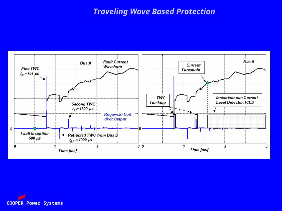
Traveling Wave Based Protection
COOPER Power Systems
Traveling Wave Based Protection
COOPER Power Systems
Field Experience with Differential Protection of Power Transformers Based on Rogowski Coil Current Sensors
Ljubomir A. Kojovic Martin T. BishopCooper Power System
Thomas A. Edison Technical CenterFranskville, Wisconsin, USA
COOPER Power Systems
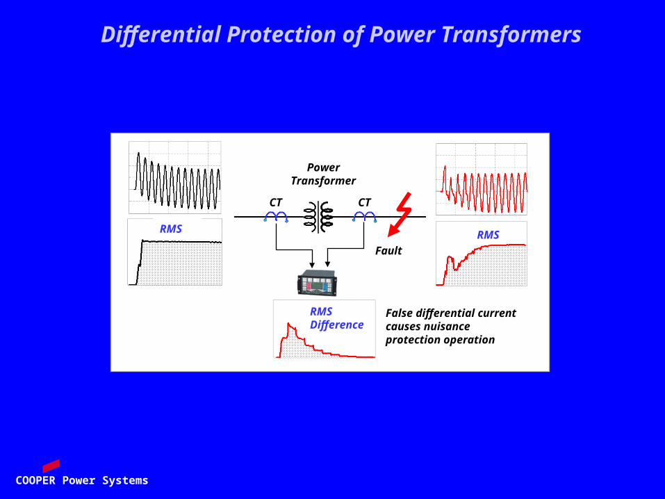
PowerTransformer
Fault
RMSDifference
False differential current causes nuisance protection operation
RMS RMS
CT CT
Differential Protection of Power Transformers

COOPER Power Systems
Blocking Zone
Dif
fere
nti
al
Cu
rre
nt
Restraint Current
Operating Zone withCurrent Transformers
Expanded Operating Zone withRogowski Coils
Differential Protection of Power Transformers

COOPER Power Systems
Non Split-CoreRogowski Coil
Split-CoreRogowski Coil
Multifunction Relay
EAF
Water Cooled Leads50 kA – 100 kA
Tapposition
EAFTransformer
Differential Protection of EAF Transformers
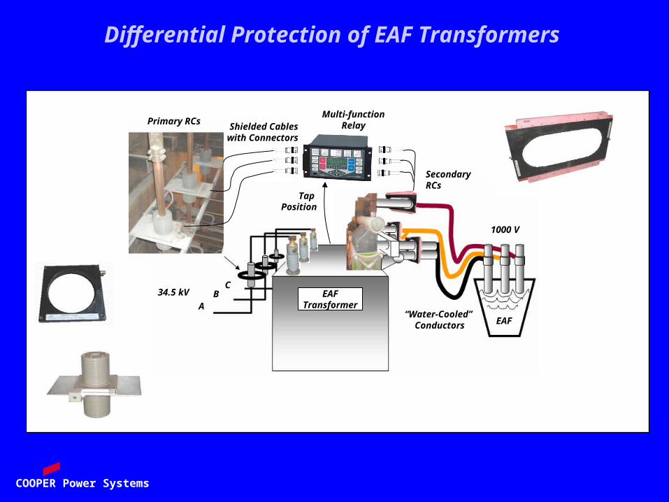
COOPER Power Systems
AB
C34.5 kV
1000 V
“Water-Cooled” Conductors
EAF Transformer
EAF
Multi-functionRelayPrimary RCs
Secondary RCs
Tap Position
Shielded Cableswith Connectors
Differential Protection of EAF Transformers
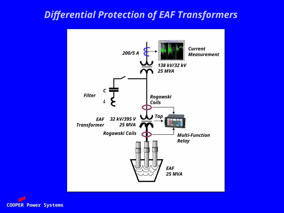
COOPER Power Systems
EAF25 MVA
32 kV/395 V25 MVA
138 kV/32 kV25 MVA
FilterC
L
Current Measurement200/5 A
Rogowski Coils
Rogowski Coils
Multi-FunctionRelay
TapEAF
Transformer
Differential Protection of EAF Transformers
COOPER Power Systems
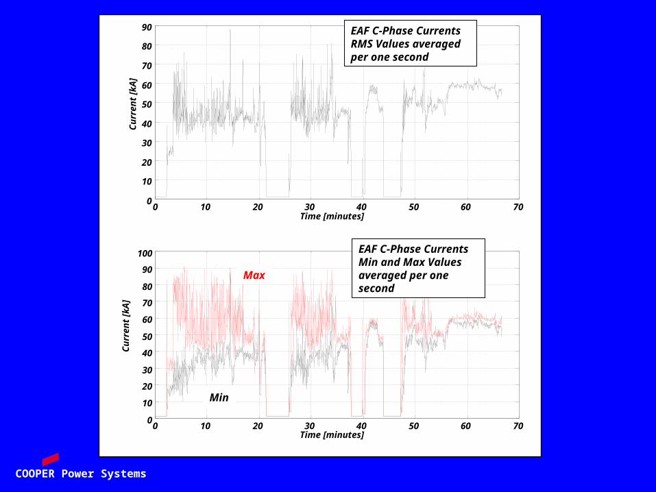
0 10 20 30 40 50 60 700
10
20
30
40
50
60
70
80
90
Time [minutes]
Cu
rren
t [k
A]
EAF C-Phase CurrentsRMS Values averaged per one second
0 10 20 30 40 50 60 700
10
20
30
40
50
60
70
80
90
100
Time [minutes]
Cu
rren
t [k
A]
EAF C-Phase CurrentsMin and Max Values averaged per one second
Max
Min
COOPER Power Systems
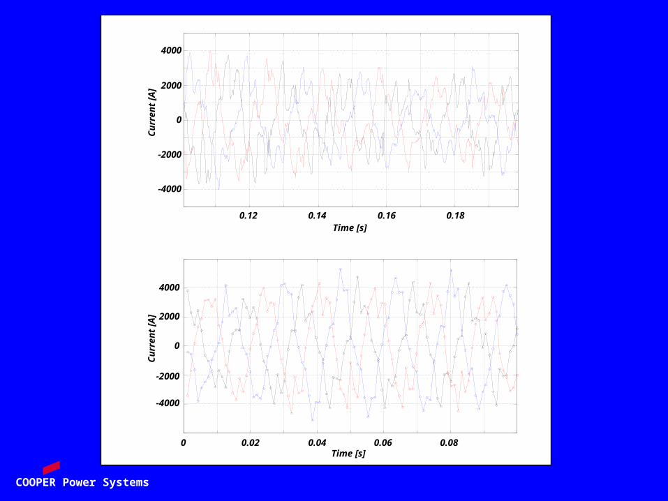
0.12 0.14 0.16 0.18
-4000
-2000
0
2000
4000
Time [s]
Cu
rren
t [A
]
0 0.02 0.04 0.06 0.08
-4000
-2000
0
2000
4000
Time [s]
Cu
rren
t [A
]
COOPER Power Systems
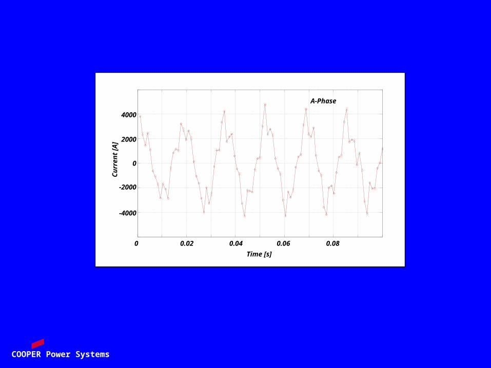
0 0.02 0.04 0.06 0.08
A-Phase
-4000
-2000
0
2000
4000
Time [s]
Cu
rren
t [A
]

COOPER Power Systems
Circuit Breaker OperatesCircuit Breaker Operates
Relay OperatesRelay Operates
Relay OperatesFault Inception
Circuit Breaker OperatesPrimary Currents
Circuit Breaker OperatesSecondary Currents
Circuit Breaker OperatesOperate Signals
Circuit Breaker OperatesRestraints Signals
Circuit Breaker OperatesTrip Signals
COOPER Power Systems