Embed Size (px)
Citation preview
Eaton Aerospace Group Conveyance Systems Division Carter® Brand Ground Fueling Equipment
SM64128 July 2010 Applicable addition manuals: None
Maintenance & Repair Manual
6” INTERNAL/BOTTOM LOADING VALVES
Model 64128

TABLE OF CONTENTS
Page 1.0 INTRODUCTION...........................................................................................................3 2.0 EQUIPMENT DESCRIPTION .......................................................................................3 3.0 AVAILABLE OPTIONS..................................................................................................3 4.0 DISASSEMBLY .............................................................................................................4 5.0 INSPECTION.................................................................................................................4 6.0 REASSEMBLY ..............................................................................................................5 7.0 TEST..............................................................................................................................5 8.0 ILLUSTRATED PARTS CATALOG...............................................................................7 FIGURE 1, 64118, 64128 & OPTIONS ....................................................................................8 FIGURE 2, 64128 PARTS BREAKDOWN ...............................................................................10 FIGURE 3 64118 PARTS BREAKDOWN ................................................................................12 FIGURE 4, PILOT VALVE PARTS BREAKDOWN ..................................................................14 FIGURE 5, DIAPHRAGM POSITION PRIOR TO INSTALLATION..........................................15 FIGURE 6, DIAPHRAGM TORQUE SEQUENCE....................................................................15

SM64128 July 2010
3
Maintenance, Overhaul & Test Instructions Models 64128 & 64118 Internal/Bottom Loading Valves
1.0 INTRODUCTION
This manual furnishes detailed instructions covering the maintenance and overhaul of Eaton’s Carter brand Models 64128, and 64118 6” Internal/Bottom Loading Valves. This manual assumes that the valves will be used with a Carter 64079 Level Sensor (s); however the 64128A, B,
64118A or B can also be used with optic probe (s) using solenoid valve (s) to affect the control of the pilot valve (s). If so, service manuals for these components should be requested from the manufacturer of the items used. Carter does not provide such items.
2.0 EQUIPMENT DESCRIPTION
The Carter 64128 family of 6” valves can be used either as a straight internal valve or for bottom loading control. The 64128 mounts directly into a 6” TTMA Tank Sump Ring or in the case of the C option it will directly replace the equivalent Whittaker F620. The 64128A is used with the Carter 64079 Level Sensor for bottom loading control with a single control pilot valve. Option “B” adds two-stage level control with two pilot valves. (Note: Early units contained provisions for only single pilot valves with the dual capability available at a later date.) Option “B” requires either the use of 64079B, C or two 64079 Level Sensors. A Carter Vent, 64078, is also available to complete the system requirements. A basic 64128 Internal Valve can be converted to a bottom-loading valve, 64128A, by adding a pilot valve.
The 64118 6” Bottom Loading Valve is used only for bottom loading. The difference between the 64128 and the 64118 is the absence of an off-loading cylinder on the 64118 and a different orifice system in the piston.
The units are spring loaded “overbalanced” piston valves. Fuel inlet pressure is routed to the inside of the piston chamber through a two-staged orifice in the center of the piston. If the piston chamber has no exit, the areas inside the piston chamber
(outer diameter of the piston) is larger than the face seal of the piston, hence the balance of pressure forces, plus the spring force will keep the piston (valve) closed.
If the piston chamber is vented through an open pilot valve, options A or B, the pressure drop across the inlet orifice reduces the piston chamber pressure significantly. The resultant balance of forces will cause the piston to open.
When the piston chamber is once again closed [pilot valve (s) closes], the balance of forces again causes the valve to close.
The 64128 or 64118 A or B is normally utilized with the 64079 Level Sensor. If so desired, a solenoid valve (s) can be used in the system to provide or deprive the pilot valve of pressure (usually routed from the bottom loading adapter) to cause the opening and closing of the valve. In this way the valve can be used with either the Civacon Liberty or the Scully Optic Probe Systems.
On the 64128, a separate air operated piston is provided to effect off-loading as desired. The direction of air pressure to this piston will cause it to pull open the main piston to allow for off-loading flow. When the air pressure is depleted, the spring forces will close both the air and main pistons.
3.0 AVAILABLE OPTIONS
The 64128 Basic Valve is designed for use as an internal valve and has no other functional controls. The 64128 can be opened for off-loading by application of air pressure to the cylinder provided. The 64118 can only be used as option “A” (64118A) since it has no off-loading capability.
The “A” option (64128A or 64118A) adds a pilot valve to the basic unit making it a bottom loading control valve. Again the 64128A can also be used for off-loading by the application of air pressure to the provided cylinder.
The “B” option (64128B or 64118B) adds two pilot valves to the basic unit to close the valve in two-stages. An orifice in the secondary pilot valve will
continue to vent the piston chamber after the primary pilot valve has closed. This orifice restricts the pressure escaping from the piston chamber to maintain the piston in a partially open position hence flow into the tank is reduced significantly. This provides a more accurate final shutoff and also helps control surge pressure on final shutoff.
A “C” option is available to interchange the Carter 64128 (A or B) with the respective Whittaker F620 Valve. The C option does not have the external (to the tank) air connection potential. It is intended only to replace an existing installation. For new installations it is recommended that the standard A
SM64128 July 2010
4
or B options be used to allow the use of a standard TTMA Sump Ring.
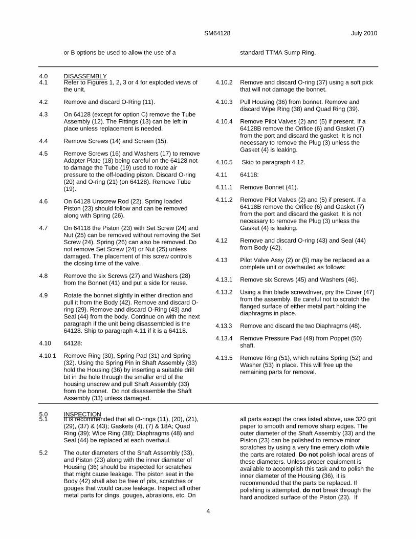
4.0 DISASSEMBLY 4.1 Refer to Figures 1, 2, 3 or 4 for exploded views of
the unit.
4.2 Remove and discard O-Ring (11).
4.3 On 64128 (except for option C) remove the Tube Assembly (12). The Fittings (13) can be left in place unless replacement is needed.
4.4 Remove Screws (14) and Screen (15).
4.5 Remove Screws (16) and Washers (17) to remove Adapter Plate (18) being careful on the 64128 not to damage the Tube (19) used to route air pressure to the off-loading piston. Discard O-ring (20) and O-ring (21) (on 64128). Remove Tube (19).
4.6 On 64128 Unscrew Rod (22). Spring loaded Piston (23) should follow and can be removed along with Spring (26).
4.7 On 64118 the Piston (23) with Set Screw (24) and Nut (25) can be removed without removing the Set Screw (24). Spring (26) can also be removed. Do not remove Set Screw (24) or Nut (25) unless damaged. The placement of this screw controls the closing time of the valve.
4.8 Remove the six Screws (27) and Washers (28) from the Bonnet (41) and put a side for reuse.
4.9 Rotate the bonnet slightly in either direction and pull it from the Body (42). Remove and discard O-ring (29). Remove and discard O-Ring (43) and Seal (44) from the body. Continue on with the next paragraph if the unit being disassembled is the 64128. Ship to paragraph 4.11 if it is a 64118.
4.10 64128:
4.10.1 Remove Ring (30), Spring Pad (31) and Spring (32). Using the Spring Pin in Shaft Assembly (33) hold the Housing (36) by inserting a suitable drill bit in the hole through the smaller end of the housing unscrew and pull Shaft Assembly (33) from the bonnet. Do not disassemble the Shaft Assembly (33) unless damaged.
4.10.2 Remove and discard O-ring (37) using a soft pick that will not damage the bonnet.
4.10.3 Pull Housing (36) from bonnet. Remove and discard Wipe Ring (38) and Quad Ring (39).
4.10.4 Remove Pilot Valves (2) and (5) if present. If a 64128B remove the Orifice (6) and Gasket (7) from the port and discard the gasket. It is not necessary to remove the Plug (3) unless the Gasket (4) is leaking.
4.10.5 Skip to paragraph 4.12.
4.11 64118:
4.11.1 Remove Bonnet (41).
4.11.2 Remove Pilot Valves (2) and (5) if present. If a 64118B remove the Orifice (6) and Gasket (7) from the port and discard the gasket. It is not necessary to remove the Plug (3) unless the Gasket (4) is leaking.
4.12 Remove and discard O-ring (43) and Seal (44) from Body (42).
4.13 Pilot Valve Assy (2) or (5) may be replaced as a complete unit or overhauled as follows:
4.13.1 Remove six Screws (45) and Washers (46).
4.13.2 Using a thin blade screwdriver, pry the Cover (47) from the assembly. Be careful not to scratch the flanged surface of either metal part holding the diaphragms in place.
4.13.3 Remove and discard the two Diaphragms (48).
4.13.4 Remove Pressure Pad (49) from Poppet (50) shaft.
4.13.5 Remove Ring (51), which retains Spring (52) and Washer (53) in place. This will free up the remaining parts for removal.
5.0 INSPECTION 5.1 It is recommended that all O-rings (11), (20), (21),
(29), (37) & (43); Gaskets (4), (7) & 18A; Quad Ring (39); Wipe Ring (38); Diaphragms (48) and Seal (44) be replaced at each overhaul.
5.2 The outer diameters of the Shaft Assembly (33), and Piston (23) along with the inner diameter of Housing (36) should be inspected for scratches that might cause leakage. The piston seat in the Body (42) shall also be free of pits, scratches or gouges that would cause leakage. Inspect all other metal parts for dings, gouges, abrasions, etc. On
all parts except the ones listed above, use 320 grit paper to smooth and remove sharp edges. The outer diameter of the Shaft Assembly (33) and the Piston (23) can be polished to remove minor scratches by using a very fine emery cloth while the parts are rotated. Do not polish local areas of these diameters. Unless proper equipment is available to accomplish this task and to polish the inner diameter of the Housing (36), it is recommended that the parts be replaced. If polishing is attempted, do not break through the hard anodized surface of the Piston (23). If

SM64128 July 2010
5
scratches are too pronounced, the parts should be replaced. Replace any part with damage exceeding 15% of local wall thickness. Use Aladdin 1200, or similar chem film treatment, to touch up bared aluminum.
The flat surfaces of the Fitting (54) and Cover (47) may be polished to remove minor scratches by using a flat plate and very fine emery cloth. Be careful to keep the parts flat during polishing and to not raise any burrs on the inside diameters that bear on the diaphragms.
6.0 REASSEMBLY 6.1 Reassembly is accomplished in essentially the
reverse order of disassembly noting the following:
6.1.2 Light lubrication of all O-rings and seals, using petroleum jelly is recommended to facilitate installation.
6.1.3 When reassembling the Pilot Valve Assy (2) or (5) use the following procedure to assure proper diaphragm retention:
6.1.3.1 Once the Poppet (50), Spring (52), Washer (43) and Ring (51) are in place, be sure that the Pressure Pad (49) is placed onto the Poppet (50) shaft with the smaller end placed onto the shaft first. The larger flat surface should be facing away from the shaft.
6.1.3.2 The two Diaphragms (48) are placed such that the loops in the diaphragms are facing the Pressure Pad (49). [In operation, the loops always face in the direction in which the pressure from the Level Sensor or solenoid valve is applied.] Smooth out the Diaphragms (48) place onto the Fitting (54) and align the six holes in all three parts. Carefully place the Cover (47) onto this assembly aligning the holes.
6.1.3.3 Start the six Screws (45) with the Washers (46) in place by hand until resistance is met. Note that if no resistance is met in attempting to hand tighten the screws, it is recommended that the Screws (45) be replaced. They are self-locking and some resistance should be felt.
6.1.3.4 Using Figure 6 mentally number the screws as shown. Using a properly set torque wrench, tighten the number 1 screw to 1.6 in-lbs. (1.8 Kg-cm), followed by tightening screws number 5, 3, 6 and 4 in that order. Then repeat the tightening sequence to 3.2 in-lbs. (2.1 Kg-cm) and then 5.3 in-lbs. (6.1 Kg-cm) respectively.
Let the assembly stand for a minimum of 15 hours retighten the screws as above to the 5.3 in-lbs. (6.1 Kg-cm) setting.
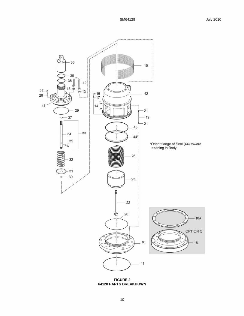
6.1.4 When installing the Seal (44) onto O-ring (43) in Body (42) be sure to smooth the surface evenly with a finger. See the installation note on Figures 2 & 3.
6.1.5 On the 64128 - Use Locktite 24221 (40) on the thread of Shaft Assembly (33) before screwing on Housing (36). On both units Locktite 24221 (40) is used also on Screws (16). Note the thread of both parts should be cleaned with the recommended Locktite cleaning solution prior to using 24221. Read the instructions on 24221 before using.
6.1.6 When installing Rod (22) it must be adjusted to provide a gap of 0.020 ± 0.005 (.305 ±. 127 mm) between the under side of the hex head of the rod and the mating flat surface of the Piston (23). a feeler gage should be used for this purpose. This will assure that the proper surge control during shutoff will be effective. On the 64118 if the Set Screw (24) and Nut (25) were removed it will be necessary to adjust the face of the Set Screw (24) to .409 ± .005 inches (10.388 ± .127 mm) from the face of the Nut (25).
6.1.7 If the Screen (15) was removed and replaced, the replacement will be provided in a flat condition and it will be necessary to carefully shape it to fit the Body (42).
6.1.8 If Fittings (13) were removed, clean up any existing Teflon tape and replace with no more than 1½ wraps. Since they will be screwed into an aluminum casting more tape may cause the mating part to crack due to excess tape.
7.0 TEST
7.1 The following test procedures will be accomplished after overhaul:
7.2 Test conditions
Test media shall be odorless kerosene, Jet A or equivalent at 75° + 15°F.
7.3 Functional Test – If testing prior to reinstalling the unit in the refueler is desired conduct the following tests:
7.3.1 Connect the inlet of the unit to a test media pressure source with a minimum of 150-psig available. Tee off the inlet pressure line to the primary pilot valve and to the secondary pilot valve on “B” option units. Install a small ball valve between the inlet pressure source and each pilot valve. Install a bleed valve between the pilot valve (s) and the ball valve. Gauges should be installed in the pressure line to the main valve’s inlet and in the line to the pilot valve (s).

SM64128 July 2010
6
7.3.2 On the 64128 connect the air port to a 100-psig air pressure source with a gauge in the line.
7.3.3 Bleed all air from the valve by applying 10-psig test media pressure to the inlet and opening the bleed valve (s) in the lines to the pilot (s). Once the air is bled, close the valve in the line to the pilot (s) and bleed all liquid trapped in the line (s).
7.3.4 Increase the pressure to the valve to approximately 25-psig for one minute and then increase it to 150-psig for one minute. Observe for external leakage during the test period. No leakage except from the main piston shall be allowed. This leakage should be limited to 100 cc/minute.
7.3.5 On the 64128, following the above test with the valve still full of liquid apply air pressure to the unit starting at 35-psig and slowly increasing slowly until the valve opens. The valve should open at an air pressure of 50-psig maximum. If testing the 64118 skip this paragraph and go on to 7.3.6. Shutoff the air pressure and bleed it to atmosphere. The valve should return to the closed position.
7.3.6 Apply liquid pressure slowly to the valve inlet and simultaneously to the pilot (s). Observe when the main piston opens. The valve shall open with an inlet pressure of 15-psig or less.

8.0 ILLUSTRATED PARTS CATALOG
Table 1.0 tabulates the parts and sub-assemblies comprising the various versions of both the 64128 and 64118 Valves with all options. The item numbers of the table are keyed to the exploded views of the unit diagrammed in Figures 1, 2 or 3.
TABLE 1.0 64128 & 64118 Bottom Loading Valves & Options
Fig.
Item
Part Number
Description
Units/ Assy
Option
Spares/10 Units/Yr.
1 1 64128 Internal Valve, Bottom Loading and Off-loading........................................
1
-
-
1 64118 Internal Valve, Bottom Loading only 1 - - 3 GF814-10D Plug .................................................. 2 Basic - 4 MS29512-10 Gasket .............................................. 2 Basic 20 2 47097 Pilot Valve, Primary (Figure 4).......... 1 A, B & C - 3 GF814-10D Plug .................................................. 1 A or AC - GF814-10D Plug .................................................. 2 Basic - 4 MS29512-10 Gasket .............................................. 2 Basic, A or AC 20 5 47097 Pilot Valve, Secondary (Figure 4) ..... 1 B or BC - 4 MS29512-10 Gasket .............................................. 2 B or BC 20 6 221087 Orifice ............................................... 1 B or BC - 7 MS29512-08 Gasket .............................................. 1 B or BC 10 8-10 Left intentionally blank 18 221039-2 Plate ................................................. 1 C - 18A 221208 Gasket .............................................. 1 C 10 11 MS29513-365 O-Ring .............................................. 1 All 10
SM64128 July 2010
8
FIGURE 1
64128, 64118 & OPTIONS

SM64128 July 2010
9
TABLE 2.0
Parts Breakdown, 64128 Basic Valve
Fig.
Item
Part Number
Description
Units/ Assy
Option
Spares/10 Units/Yr.
2 11 MS29513-365 O-Ring .............................................. 1 All 10 12 47238 Tube assembly ................................. 1 A, B - 13 2404-04-02 Fitting................................................ 2 A, B - 14 90056A144 Screw................................................ 2 All - 15 221036 Screen .............................................. 1 All - 16 GF16998-45 Screw................................................ 12 All - 17 GF960C416 Washer ............................................. 12 All - 18 221032-2 Adapter Plate .................................... 1 A & B - 221039-2 Adapter Plate .................................... 1 C - 18A 221208 Gasket .............................................. 1 C 10 19 221077 Tube ................................................. 1 A & B - 20 MS29513-256 O-Ring .............................................. 1 All 10 21 MS29513-006 O-Ring .............................................. 2 A & B 20 22 221033 Rod ................................................... 1 All - 23 47219 Piston................................................ 1 All - 26 221038 Spring ............................................... 1 All - 27 GF35275-265 Screws .............................................. 8 All - 28 GF35338-138 Washers............................................ 8 All - 29 MS29513-157 O-Ring .............................................. 1 All 10 30 GF16633-4050 Ring ................................................. 1 All - 31 220438 Spring Pad........................................ 1 All - 32 220437 Spring ............................................... 1 All - 33 47095 Shaft Assembly................................. 1 All - 34 220448 Shaft......................................... 1 All - 35 GF16562-238 Pin............................................ 1 All - 36 220450 Housing............................................. 1 All - 37 MS29513-112 O-ring................................................ 1 All 10 38 220453 Wipe Ring ......................................... 1 All 10 39 Q4325-366Y Quad Ring......................................... 1 All 10 40 24221 Locktite ............................................. 1 All 41 47099 Bonnet .............................................. 1 All - 42 220458 Body.................................................. 1 All - 43 MS29513-437 O-ring................................................ 1 All 10 44 221040 Seal .................................................. 1 All 10
SM64128 July 2010
10
FIGURE 2 64128 PARTS BREAKDOWN

SM64128 July 2010
11
TABLE 3.0 Parts Breakdown
64118 Basic Valve
Fig.
Item
Part Number
Description
Units/ Assy
Option
Spares/10 Units/Yr.
3 11 MS29513-365 O-Ring .............................................. 1 All 10 14 90056A144 Screw................................................ 2 All - 15 221036 Screen .............................................. 1 All - 16 GF16998-45 Screw................................................ 12 All - 17 GF960C416 Washer ............................................. 12 All - 18 221117 Adapter Plate .................................... 1 A & B - 221039-2 Adapter Plate .................................... 1 C - 18A 221208 Gasket .............................................. 1 C 10 20 MS29513-256 O-Ring .............................................. 1 All 10 23 47248 Piston ............................................... 1 All - 24 221109 Set Screw ......................................... 1 All - 25 GF51971-3 Nut .................................................... 1 All - 26 221038 Spring ............................................... 1 All - 27 GF16996-12 Screws .............................................. 8 All - 28 GF35338-138 Washers............................................ 8 All - 29 MS29513-157 O-Ring .............................................. 1 All 10 40 24221 Locktite ............................................. 1 All 41 221108 Bonnet .............................................. 1 All - 42 221116 Body.................................................. 1 All - 43 MS29513-437 O-ring................................................ 1 All 10 44 221040 Seal .................................................. 1 All 10

SM64128 July 2010
12
FIGURE 3 64118 PARTS BREAKDOWN

SM64128 July 2010
13
TABLE 4.0 Pilot Valve Parts Breakdown
Fig.
Item
Part Number
Description
Units/ Assy
Option
Spares/10 Units/Yr.
1 2 47097 Pilot Valve Assy, Primary.................. 1 A, B, AC & BC - 4 45 LP35275-230 Screw....................................... 6 A, B, AC & BC - 46 GF620C6 Washer..................................... 6 A, B, AC & BC - 47 220441-1 Cover ....................................... 1 A, B, AC & BC - 48 220445 Diaphragm ............................... 2 A, B, AC & BC 20 49 220443 Pressure Pad ........................... 1 A, B, AC & BC - 50 220434 Poppet...................................... 1 A, B, AC & BC - 51 POL-18 Retaining Ring ......................... 1 A, B, AC & BC - 52 220444 Spring....................................... 1 A, B, AC & BC - 53 220442 Washer..................................... 1 A, B, AC & BC - 54 220433 Fitting ....................................... 1 A, B, AC & BC - 1 5 47097 Pilot Valve Assy, Secondary............. 1 B or BC - 4 45 LP35275-230 Screw....................................... 6 B or BC - 46 GF620C6 Washer..................................... 6 B or BC - 47 220441 Cover ....................................... 1 B or BC - 48 220445 Diaphragm ............................... 2 B or BC 20 49 220443 Pressure Pad ........................... 1 B or BC - 50 220434 Poppet...................................... 1 B or BC - 51 GF16633-4018 Ring ......................................... 1 B or BC - 52 220444 Spring....................................... 1 B or BC - 53 220442 Washer..................................... 1 B or BC - 54 220433 Fitting ....................................... 1 B or BC - KD64128-1 Kit, seal replacement for 64128A Valve. Contains items 4, 11, 20, 21, 29, 37, 38,
39, 43. 44 & 48. KD64128-2 Kit, seal replacement for 64128 Basic Valve. Contains items 4, 11, 20, 21, 29, 37,
38, 39, 43 & 44. KD64128-3 Kit, seal replacement for 64128B Valve. Contains items 4, 7, 11, 20, 21, 29, 37,
38, 39, 43, 44 & 48. KD64129-3 Kit, seal replacement for 47097 Pilot Valve Assy. Contains items 4 & 48. KD64128-4 Kit, seal replacement for 64128AC Valve Assy. Contains items 4, 11, 18A, 20, 29,
37, 38, 39, 43, 44 & 48. KD64128-5 Kit, seal replacement for 64128BC Valve Assy. Contains items 4, 7, 11, 18A, 20,
29, 37, 38, 39, 43, 44 & 48. KD64118-1 Kit, seal replacement for 64118A Valve. Contains items 4, 11, 20, 29, 43, 44 &
48. KD64118-2 Kit, seal replacement for 64118B Valve. Contains items 4, 7, 11, 20, 29, 43, 44 &
48. KD64118-3 Kit, seal replacement for 64118AC Valve. Contains items 4, 11, 18A, 20, 29, 43,
44 & 48. KD64118-4 Kit, seal replacement for 64118BC Valve. Contains items 4, 7, 11, 18A, 20, 29,
43, 44 & 48. Notes: 1. All part numbers beginning with "GF" are interchangeable with those beginning with either "AN" or "MS". If
three numbers follow the “GF” it is interchangeable with an "AN" part, otherwise it is interchangeable with an "MS" part of the same number.
2. The recommended spare parts shown above are the number required to support 10 units for one year or each overhaul whichever is sooner. These quantities do not include replacement spares for intermediate replacement of parts required by abuse or misuse of the equipment. The recommended quantities are based on the ratio of spare parts sold for each unit during a one-year period of time. The actual quantity required will vary from location to location.

SM64128 July 2010
14
FIGURE 4 PILOT VALVE PARTS BREAKDOWN

SM64128 July 2010
15
FIGURE 5 DIAPHRAGM POSITION PRIOR TO INSTALLING
FIGURE 6 DIAPHRAGM TORQUE SEQUENCE

Eaton Aerospace Group Conveyance Systems Division 9650 Jeronimo Road Irvine, CA 92618 Ph (949) 452-9500 Fax (49) 452-9992