Embed Size (px)
Citation preview

2,217,364 Oct. 8, 1940. F. B. HALFORD ET AL
CONTROL SYSTEM FOR THE POWER UNITS; 0F AIRCRAFT
5 Sheets-Sheet l
3/
Filed Nov. 4, 1936
E5, (yaw: - \ -
? 27/6

2,217,364 Oct. 8, 1940. F. B. HALFORD El‘ AL CONTROL SYSTEM FOR THE POWER UNITS 0F AIRCRAFT
Filed Nov. 4, 1936 5 Sheets-Sheet 2
0 m
w w Sig w
I600 I700 [800 /900 2000 2/00 2200 2300 2400 2500 2600 2700 2800
BY; '0 2000 4000 6000 8000 /0000 ./2000 M000 00-02
Fig. 3; 90
amt R
L mUJu Eao WHM BS. TMWM ,r??4x5x6x x
B mx OHX ow?zxx w w w w w w
ATTORNEYS

2,217,364 Oct. 8, 1940. F. B. HALFORD ET AL
CONTROL SYSTEM‘ FOR THE POWER UNITS 0F AIRCRAFT
Filed Nov. 4, 1956 5 Shée'ts-Sheet a
Oct. 8, F_ B_ HALFQRD Er AL
CONTROL SYSTEM FOR THE POWER UNITS 0F AIRCRAFT
Filed Nov. 4, 1936 5 Sheets-Sheet 4
50
200 24500 4000 50.00 8000 /0000 /2000 M000 #5000 /8000 20000
‘i- IHVEHTOR'S "
TB . Half-0rd E. 5'. MovL'l:
BYZ' ., .
ATTORNEYS

Oct. 8, 1940. F. B. HALFORD ET AL
CONTROL SYSTEM FOR THE POWER UNITS 0F AIRCRAFT
Filed Nov. 4, 1956
Fig. 6.
2,217,364
5 Sheets-Sheet 5
Mad/was.‘ ?B/ZQFORA,
7- gs/‘fazar.
9%

Patented Oct. 8, 1940
UNITED 'STATES
2217,2364.
PATENT OFFICE j . 2,217,364
CONTROL SYSTEM FOR UNITS OF AIRCRAFT ' "
Frank Bernard Halford and Eric Stanley Moult, London, England ~ 7.
Application November 4, 1936, Serial No. 109,186 In Great Britain November 12, 1935 ' '
15 Claims.
This invention relates to control systems for the power units of aircraft and of the kind ‘com prising an internal combustion engine and a vari able pitch airscrew whose pitch is automatically
5 controlled by .a governor driven by the engine. With an airscrew of ?xed pitchithe airscrew
speed is both a measure and a limitation of the power absorbed, engine speed regulation beingv effected by manual or automatic control of a
10 throttle or the like so that power output settles itself in accordance with altitude and the air screw characteristics. Though a variable pitch airscrew facilitates control by the pilot of the engine output, automatic governor control of the
15‘ pitch allows freedom of choice of the engine speed irrespective of the throttle opening so that airscrew speed is no indication of the power out put. Since therefore the power output of a given engine depends upon the product of its speed of
m revolution and the brake mean effective pres sure, the pilot is only able to estimate the engine output by correlating observations of the engine speed, induction pressure and altitude. Economic engine operation, with independent
25 speed and throttle control as heretofore em ployed, is open to the disadvantage that, apart from necessitating reading by the pilot of charts or tables, the test upon which such charts or tables are based is usually made under maximum
30 conditions, that is to say when the engine is su percharged or “boosted” the tests for climbing and cruising are usually conducted with the ap propriate maximum declared boost and maximum declared engine speed applied simultaneously. If
35 therefore the maximum boost pressure is used at lower engine speeds durability of the engine may be adversely affected. Thus, there is nothing to prevent the pilot from ?ying at low engine speed and‘high boost pressure, with a resultant risk
40 that reliability of the engine will be impaired due to detonation. Similarly, it is possible with inde pendent control, for example in an emergency when maximum engine speed and boost pressure are temporarily required, for the pilot ?rst to raise the boost pressure without at the same time correspondingly increasing the engine speed with consequent risk ofdetonation. In order to guard against abuse of this nature precautions have hitherto had to be taken which necessarily re
50 duced the maximum available engine output.
4
The present invention has for its object not. only to overcome the above difficulties but also to simplify ' the operation and installation of the control mechanism and at the same time improve
55' its sensitivity. '
(Cl. I'm-435.6) In a control system according to the present
invention, the airscrew pitchand a factor or fac tors which determine the mean effective pressure of the engine are in?uenced by one and the same master control device under the control of the 5. pilot. Thus, the mean e?ective pressure cannot be modi?ed without at the same time correspond-~ ingly altering the engine speed, so that risk of detonation, due for example, in a supercharged engine, to maximum boost pressure being em- 10 ployed at a low engine speed, isreduced.
Preferably the governor controlling the air screw pitch, and a device controlling the boost pressure are connected to the master control de vice so that for any given increase or decrease 15 of engine speed, above the minimum‘ cruising speed range, a corresponding increase or decrease of the boost pressure is automatically effected. The most suitable compromise of boost pressure and engine speed for reliability and economy may 20 thus be determined during manufacture, safe and \ reliable operation of the engine being ensured whatever the load factor selected by the pilot.
Preferably movement of the master control de vice by the pilot from the normal or starting po- 25 sition through a preliminary stage towards in crease‘of the engine input does not affect the boost pressure control device or the governor con trolling the airscrew pitch, whilst continued
- movement of the master control device in?uences 80 the boost pressure control device to increase the boost pressure with a simultaneous increase in the engine speed, yet further movement of the master control device through a second stage in?uencing the boost pressure control device to increase the boost pressure with a simultaneous but relatively small increase in engine speed, movement of the master control through a third stage causing the engine speed to be increased with simultaneous, but relatively small, increase ‘ or possibly a decrease of the boost pressure. 0 Though a supercharger or booster will serve
approximately to maintain sea level power up to ~a critical altitude, there is a serious risk of det onation taking place if the input regulating de- 45 vice is fully opened at or near ground level. With a view to guarding against this difficulty a boost control device is usually provided compris ing a closed chamber subject to the boost pres sure and containing a collapsible element in the form of a bellows or a stack of collapsible cap sules, one end of the bellows or stack being con nected to a valve controlling a servo piston for ‘in ?uencing the device (e. g. throttle) controlling the input to the engine, whilst the other end of 55

5
20
25
80
Ill
50
10
75
2 .
the bellows is connected to an‘ adjustment stud or, in the case of a boost control of the “variable datum” type, to a plunger or rod operatively con nected to the pilot's control whereby the pilot adjusts the input of the engine. Thus, with the ‘variable datum boost control, any given adjust ment of the pilot’s control results in a de?nite alteration in the boost pressure and maximum permissible boost pressure cannot be obtained, below the critical altitude, until the said lever has been moved to the fully “open” position. When the present invention is applied to a
power unit of the ‘type above indicated and the boost control device is of the variable datum type, the master control device may be so con nected to the boost control device and‘ pitch gov ernor that, for any given setting of the master control device, the resultant power output con forms approximately to the constant speed line on a. conventional engine performance curve. Thus, for example, for any given setting of the pitch governor and boost control device below the critical altitude sea level power would be in creased'approximately at the rate of 1.1% per 1000 feet while, above the critical‘ altitude, power would decrease for any given engine speed. As wlLbe appreciated this result differs from
that obtained for any given boost pressure with a. ?xed pitch airscrew since the engine speed and output obtainable are then largely governed by the characteristics of the airscrew. 'Further, since with the present invention engine speeds will be automatically increased with boost pres sure at all altitudes, the response to a variation of the engine input, e. g. throttle, opening, at moderate altitudes would be somewhat more marked than with independent control systems as hitherto employed since, with the latter, for -a given setting of the boost control device, the sea level power curve ?attens as maximum speeds are approached so that at high speeds the ratio of power increase to increase of engine speed tends to be low, or the power may even decrease with increase in the speed. When the engine of a power unit to which the
invention is applied is of the vapourised charge spark ignition type the master control device may also influence a member for regulating the timing of the ignition. The arrangement is then preferably such that as the master control de vice is moved by the pilot from the “closed” or starting position the timing of the ignition is ad vanced rapidly until the cruising speed range is reached during which the rate of ignition ad vance decreases with increasing speed, the tim ing being thereafter retarded as the speed in creases within the climbing speed range until, for high, e. g. take-off, speeds, the timing re mains substantially constant or is slightly ad vanced with increasing speed.
The timing of the ignition is primarily a func tion ofengine speed and the pressure on the in duction side of the engine. Since therefore con trol of the engine speed and the boost pressure are co-related with the ignition timing by rea son of the common or master control device, an tomatic regulation of the ignition timing, as by means of a governor, is rendered unnecessary. A device may be provided for controlling the
mixture strength of the charge, and this device connected to the master control device. The in terconnection between the master control device and the mixture control device may be such that, as the master control device is moved to increase the input to the engine the mixture is enriched
2,217,364_ for starting and slow running speeds and is then weakened for cruising speeds. As the speed in creases the mixture is enriched, progressively, as climbing and emergency speeds are attained. This result may be obtained, for example, by causing the degree of opening of an air control valve or the like to be retardedas the master control device is actuated by the pilot to increase the. engine output, e. g. to increase the effective opening of the throttle. In the accompanying drawings Figure 1 illustrates one arrangement embody
ing the invention, Figures 2 and 3 are curves indicating varia
tions in power output, boost pressure and igni tion timing, at various altitudes and engine speeds, with the arrangement shown in Figure 1. Figure 4 shows a preferred arrangement, em
bodying the invention, Figure 5 indicates, by means of curves, the
variations in power output and boost pressure obtained at several engine speeds and altitudes with the control apparatus shown in Figure 4, Figure 6 shows a further arrangement, also ac
cording to the invention, but in which the en gine is of the fuel injection compression igni tion type.
It should be understood that various construc tions shown in the drawings are not only given by way of example but are, for the most part, illustrated purely diagrammatically. In the arrangement shown in Figure l, the
pitch of the airscrew- blades A1 is automatically controlled by a governor B so that the said pitch is automatically modi?ed in accordance with variations in the speed of the engine indicated at A. To this end each blade A1 is rotatable about a spider arm A2 attached to the airscrew shaft A3. The shaft A3 has an internal chamber A4 and is furnished with a cylindrical cap A5 which is longitudinally movable on the shaft A3 under hydraulic pressure supplied to the cham ber A4 as hereinafter described. The cap A5 has two studs A6 which engage slots in lugs A" car ried by the blades A1. When the airscrew is in operation centrifugali and aerodynamic forces tend to turn the blades A1 into coarse or maxi mum pitch against the said hydraulic pressure. The governor generally indicated at B com
prises a pump B1 driven by the engine and to I which oil is delivered under the engine oil pres sure, say 50'lbs. per square inch, through a pipe B2, the pump B1 delivering this oil, say at a pres sure of 200 lbs. per square inch, through a pipe B3 to a cylinder 3‘. A by-pass valve B5 determines the maximum pressure on the delivery side of the pump B1 by automatically returning oil from the pipe 133 to the pipe B2 when the said maxi mum oil pressure is exceeded. The cylinder B4 contains a piston valve B?'which is controlled by a member B’l actuated .by governor ?y weights B8 driven by the engine. The member B" is load ed by a spring B9 and carries a spindle B1° fur nished with two collars B11 and B12. The valve B6 controls the supply of oil under pressure from the cylinder B4 through a pipe A8 to the cham ber A4 and the discharge of oil from the latter through the pipe A8 to a pipe A” and thence back to the engine. 7
The effective tension of the loading spring B9 can be adjusted by a sleeve C3 actuated by a gear wheel C2 carried by a larger gear wheel C1 which is operated by a rack C, hereinafter referred to as the speed control device. Extreme upward .movement of the sleeve Ca causes a ?ange C4
15
25
30
50
55
60
76

iii
—
40"
(3O
65
2,217,804. thereon to engage the collar Bu thus positively holding the valve.B° up to give coarse pitch of the airscrew A1 since the valve B‘ is then held raised so as to bring the pipe A8 into communi cation with the pipe A'. Conversely, extreme downward movement of the sleeve C3 causes the ?ange C4 to engage the collar BH and thus posi tively hold the valve B6 downwards to give ?ne airscrew pitch. Under steady ?ying conditions the ?y weights B8 are held in' equilibrium by the tension of the spring 13' acting against the cen trifugal force, variations in engine speed causing adjustment of the valve Bo and thus effecting variation of the airscrew pitch to tend to main tain the engine speed substantially constant. The speed control C is connected by a pivoted
link D3 to a cam n which controls a change-speed gear between the engine and the airscrew, the cam n being connected by a pivoted link D2 to an ignition control device F which is connected by another pivoted link D5 to a boost control cam E. The boost control cam E is connected by two links D1 to a master control device comprising a lever D under the pilot’s control and hereinafter referred to as the pilot’s lever. '
It is known that with certain high speed types of machine the airscrew blades are liable to be stalled at. “take-oi!” if the take-01f speed is too closely related to the maximum level ?ight speed.
-- It is therefore desirable to provide for high air screw speeds during "take-off” in order that the blades shall be unstalled and the maximum thrust developed. In the constructions above de scribed this has been achieved by allowing the engine to “overspeed"'while developing its “take off” power. , ‘ _
With some types of engine, however, this over speeding may give rise to detonation or destruc tive mechanical ‘ forces and in such cases a change-speed gear may be provided between the engine and the airscrew. In the arrangement shown the cam 12. acts through a bell crank lever 121 on a spring-loaded piston valve n’. .The valve n2 controls a supply of oil under pressure through
_ a pipe 11,3 to opposite sides of the servo piston 1:‘ arranged in a servo cylinder n‘. The servo pis ton n4 is connected, as shown, to a member n" for controlling the ratio of the change-speed gear through which the drive is transmitted to the airscrew AL The ignition control device F is constituted by
a plate cam comprising a cam slot F1 engaged by a follower F’ carried on one_ arm of a bell crank . lever Fa pivoted at F‘. ‘The other arm of the lever F‘3 is connected through links F5 to the contact-breakers F‘3 of the .magnetos F’. The basic timing of the magnetos is controlled in the known manner by a governor or governors (not shown) driven by the engine, supplementary ig nition timing being affected by the device F, as hereinafter described. The boost control device is of the variable da
tum type and comprises a chamber E1 containing a stack of evacuated capsules E". One end of the stack E2 carries a spindle E3 which passes through a gland in the head of the chamber E1 and is biased upwards by a spring, the boost con-' trol cam E acting on the end of the spindle E3. "The lower end of the stack E2 acts on a piston
- - valve E4 arranged in a cylinder Els furnished with ?ve ports, namely, an inlet port E5 for oil under pressure, two discharge ports E7 and E", a port ' E9 leading to a servo cylinder G5 on one side of a servo piston G", and a port E1° leading to the
~ servo cylinder (Ii5 on the other side of the piston
G‘. The chamber E1 is in permanent communi cation through a pipe H1 with'tthe induction pipe of the engine -A, to which air is supplied by" a supercharger or booster H driven by the engine, the boost control cam E being moved by the pilot’s lever D so that a de?nite boost pressure is provided for each position of the lever D with in the,operating range. The carburettor J is of the type whereby the
air/fuel mixture strength is automatically con trolled. To this end the boost pressure acts 'through a pipe J1 on a stack of evacuated cap sules J2 arranged in a closed chamber J3 so as to raise a needle J4 and enrich the mixture with
- increasing boost pressure. A second chamber J‘, in permanent communication with the atmos phere through a port J‘, contains a stack of evac uated capsules J’l which controls a needle Ja so that with increasing altitude the fuel supplied to the carburettor J is reduced, ‘as is necessary to correct 'for atmospherlc'density effects on the fuel/air ratio. The characteristics of the carbu rettor may be determined to suit requirements by initially adjusting the stacks of capsules J‘, J" or changing the carburettor Jets and the needles J4, J8. _ '
The datum of the mixture control capsules J2 is arranged so that it can be altered by the pilot to vary within limits the range of mixture strengths. , ~
Thus, although during short distance ?ying and manoeuvring a normally rich mixture setting can be employed, the pilot can set a weak ‘mixture for economical cruising over long distances when he so desires. In this respect it should be un derstood that where extreme economy of engine operation is required mixture ‘strength will be reduced to the maximum economy point. An engine running under these. conditions is, how ever, somewhat susceptible to movement of the controls, that is to say the stability of operation of the engine and facility for manoeuvring are restricted if the carburettor is set for a perma nently weak mixture in the cruising range. This
culty is overcome by providing means where by the mixture is temporarily enriched while the
I pilot’s lever D is being adjusted. ‘In the arrangement shown the pilot’s lever D
is provided with a knob D6 loaded by a spring D7 and having a metallic contact D3 for cooperation with a contact D” connected to earth through the lever D. The contact D8 is electrically connected through a conductor 51 and solenoid S to one terminal of an electric battery 82 the other ter minal of which is connected to earth, a manually controlled switch S3 being provided between the conductor 81 and the earthed side of the bat tery B’. When the pilot grasps the head D‘ of the lever
D the weight of the pilot's hand closes the con tacts Da and D‘ thereby energising the solenoid S. An armature S4 is thus raised and a bell
~ crank lever B5 is turned in the counterclockwise
as,
I.
I'
40
60"
direction as viewed in the drawing againstthe = action of a spring 8°. This rotation of the bell crank lever S‘ turns an eccentric bush 8'' in the clockwise direction and raises the fulcrum of a lever S8 connected at one end to the stack of cap sules J2 arranged within the chamber J3 which communicates with the induction pipe of the en gine. Thus, by raising the fulcrum point of the lever S“ the needle J4 is raised and the mixture strength is temporarily enriched. When the pilot releases the lever D the solenoid S is deen
'ergised and the spring 8° returns the fulcrum'
w.
70
75

10
50
Wi
(iii
70
75
4 g .
of the lever Sa so that the mixture strength will now be as determined by the boost pressure. If the pilot desires to cruise over an'appreciable length of'time at a rich mixture strength he closes the switch S3 so that the fulcrum of the lever S8 is retained in its raised position even after the pilot has removed his hand from the lever D. A similar effect may be obtained by providing the knob D6 with‘ means cooperating with a latch on the body of the lever D so that the pilot can at will latch the knob D'3 in its downward position and thus retain the lever S8 in its raised position. The throttle G is controlled, through a link G1,
bell-crank lever G2 and lost motion device G’, from a lever G4 connected to the pilot's lever D through the pivot of the links D, the rod of the servo piston G6 being pivotally connected to the lever G4. The maximum opening movement of the throttle G is determined by a stop G7. The lost motion device G3 permits further
movement of the pilot's lever D to increase the engine speed after the throttle G has been fully opened. For example, the boost pressure permis sible at 2000 revolutions per minute corresponds to a fully open throttle at 12,000 feet altitude (see Figure 3). The throttle G is then against its stop G’I so that if, while ?ying under these conditions, the pilot wishes to increase the en gine speed, say, to 2200 or 2400 revolutions per minute, the pilot's lever D can be moved to effect the necessary alteration in the loading of the governor B, and therefore the necessary reduc tion in airscrew pitch, since the spring of the lost motion device G‘ will yield. It will be ap preciated that the spring of the lost motion de vice G3 is su?iciently stiff to act as a solid link except under the circumstances referred to above. The operation of the control apparatus shown
in Figure 1 is as follows. With the lever D in the starting position indi
cated at I the ?ange C4 on the sleeve C“ posi tively holds the valve B6 in its fully raised posi tion, thereby setting coarse pitch of the airscrew A1. Initial movement of the pilot's lever D from the starting position I acts through the links D1, lever G4 and bell-crank lever G2 to increase the effective opening of the throttle G. -The follower 1‘‘2 of the ignition control device F11 is now in a straight part of the slot F1, the spindle E3 bears against a concentric part of the boost control’ cam E while the projection on the cam n has not yet contacted with the bell crank lever n1", so that neither the boost control device El nor the igni tion timing nor the change-speed gear between the engine and airscrew are as yet affected by the lever D. The valve i36 is moved downwards but does not alter the aircrew pitch until the throttle G has been appreciably altered. , The engine is now started and warms up and
gathers speed. With continued movement of the lever D the valve B6 moves down until the pipe A0 is brought into communication with the cylin der 3* above the valve B6 so that the pitch of the airscrew A1 vis reduced. The resultant in crease in the engine speed however causes the governor B to raise the valve B“, thus tending to maintain the constant aircrew pitch for a given position of the lever D . With continued move ment of the pilot's lever D, however, the cam F advances the ignition timing over and above the basic advance effected by the ignition timing gov ernor or governors. At the same time the boost
' control cam E commences to in?uence the boost control device E1 whilst the loading of the gover
2,217,804 nor B is increased. The engine speed at which
' the governor B will close the pipe .A8 is thus in creased so that the engine tends to speed up. This in?uence commences somewhat below the minimum cruising speed, say, at 1600 revolu tions per minute. The downward movement of the spindle E3, in effect, alters the datum of the boost control device E1, thereby tending to move the valve E4 downwards to admit oil under pres sure through the port E10 to the servo cylinder G5 on the left of the piston G6, and to allow oil to be discharged from the cylinder G5, on the right of the piston G6, through the ports E9 and E". The tendency therefore is for the piston G6 to open the throttle G still further, but the rising engine speed and consequent increase in the induction pipe pressure tends to collapse the capsules E2 and thus restore the valve E4 to a central posi tion of equilibrium. ' '
Thus, for any given engine speed there is a cor responding boost pressure to give an output suit able for level ?ight conditions, the cruising power output increasing progressively as the pilot’s lever is moved to increase the effective opening of the throttle G. The ignition control cam F rapidly advances the ignition up to the minimum cruising speed, say, 1700 engine revolutions per minute. The law governing the most suitable ratio of
engine speed to induction pressure at speeds above the minimum cruising speed will vary for different engines and can only be satisfactorily determined from a detailed knowledge of the en gine characteristics. In principle, however, it may be desirable, at any given speed within the cruising speed range, to cruise at a determined fraction of the absolute induction pressure which, with the weakest fuel mixture and the minimum ignition advance for maximum power at that speed, results in signs of incipient detonation with the type of fuel selected. As the engine speed increases within the cruis
ing speed range, say 1700 revolutions per minute to 2200 revolutions per minute, advance of the ignition timing will continue to be progressive (as hereinafter described with reference to Figure 2) the rate of ignition advance being dependent on the power output selected for any given en gine speed. The pilot's lever D is now in the position in
dicated at 2, namely, at the end of the range of movement l-2, hereinafter referred to as the “?rst stage" and corresponding to an engine speed range up to,‘ say,‘ 2200 revolutions per minute, that is to say, including the slow running, starting and cruising speed ranges. During a "second stage” of movement of the
pilot's lever D from the position 2 to the position 3, an increased power output is obtained for climbing and emergency conditions. To this end, the resulting movement of the throttle G and of the boost control cam E causes a marked increase in the boost pressure, but a relatively small in crease in the engine speed. Thus, above the cruis ing speed range, say, from 2200 to 2400 revolutions per minute, the boost pressure increases rapidly and concurrently with increase of the airscrew speed until the output required, say, for climb ing or emergency conditions in level ?ight, is at tained. During the “second stage” 2—3 the cam F gradually retards the ignition, thereby per
10
16
25
80
85
45
70 mitting the use of high boost pressures without - detonation which is further guarded against by automatic enrichment of the mixture strength due to the high boost pressure acting on the stack of capsules J2 to raise the needle J‘ and admit

IS
75
2,917,804 more fuel. It will be appreciated that fuel con~ sumption, under emergency and climbing condi-{ tions which are usually transitory, is of minor?
' “fore top dead centre. importance, ‘1
The pilot's lever D is now at the position 3,1. e3" at the end of the "second stage." Movement of _ this lever from the position .3 towards the position 4, that is to say through a f‘third stage," gives the high airscrew speeds necessary for “taking-off.” Movement of the pilot's lever through this third stage causes a considerable increase inthe engine speed with a relatively small change in the boost pressure. , ‘Thus, for example, for engine speeds. between 2400 and 2800 revolutions per minute,_ the curve indicating boost pressure, as shown in Figure 2, is substantially ?at between 2400 an 2500 revolutions per minute. ' Within the usual ?ying speed range the ‘cam n
lies clear of the bell crank lever n1 so that the valve n2 is held in the position shown and‘1'the servo piston 124 holds the member 11° in the posi tion shown, that is to say so that the two-speed gear 11'' is set for low airscrew speed, for example two-thirds of the engine crankshaft revolutions per minute. This low gear ratio is maintained for all positions of the pilot's lever D from low speed or starting through the cruising and climb ing ranges. When, however, the. pilot's lever is moved into the "third stage” for "take-o?” the cam n moves the valve n’ downwards so that the oil under pressure is supplied to the cylinder n‘ below the piston n4 which moves the member n° upwards into the high speed position in which, for example, the airscrew A1 is driven at'the same speed as the engine crankshaft. ‘After- the ma chine has takenoif and the pilot throttles back to suit climbing conditions, the cam 1: leaves the bell-crank lever 11.1 and the change-speed gear n7 is thereby changed back to- the position shown, that is to say for low airscrew speeds ' » - During the third stage of movement of the
pilot's lever D the ignition control cam F leaves the ' ignition timing substantially unaltered though the ignition may be advanced slightly (as! shown in Figure 2) relatively to the timing which obtains at the end of the emergency or climbing speed range, say, 2400 revolutions per minute.v When, say, at high altitudes, the throttle G is
moved to its fully open position due to the piston. G6 being moved to the righthand end of the cylin der G5, the engine sped can be still-further in creased by the pilot’s lever D since the lost mo- e tion device G3 will yield and thus permit the movement of the lever D to increase the loading of the spring B9 and thus increase the engine speed. . ,
For the second and .third stages the pilot’s lever has no centralor intermediate position. but is moved to the end of the stages of 'movement as determined by the gates in the cooperating quad rant. An appreciable lever movement is prefer ably provided so as to avoid undesirably steep op erative surfaces on the cams E and F. In this. .respect the quadrant of the lever D has gates, as shown, so that the pilot will be aware of passing from the cruising speed range into the climbing and emergency speed range or from the latter into the take-01f or "over-speed" range.
Figures 2 and 3 indicate, by means of curves, variations in the output at various altitudes and engine speeds of a power unit as- described with reference to Figure 1. . In Figure 2 engine revolu tions per minute (within the ?ying speed range) are plotted as abscissae and the three curves X, Y and Z ‘ represent, respectively, variations of en
5 gine output at sea level in percentage of the take oifo'utput. boost pressure in pounds per square inch absolute and ignition timing in degrees be
In Figure 3 the seven curves :r1, 2”, x3, w‘, x5, :?'and :c'’ are plotted with altitudes in feet as abscissae and power outputs. in percentage of the take-oi! output, as ordinates. From these curves it will be seen that with a
' take-oi! speed of 2800 revolutions per minute at sea level the boost pressure is approximately 17.7 pounds per square inch as shown at Y1 on the curve Y, whilst the take-off. output is~approxi- - mateiy 100% as shown at X1 on the curves xand'. :c". At‘ the maximum climbing speed of ‘2400 revolutions per minute and up to 2200 feet altitude the boost pressure of 17.7 pounds per square inch
an 5
is maintained as shown at Y2 on the curve Y, the 1 ' power output being approximately 90% at 2200 feet as‘ shown at X2 on the curve x1. At the maximum. cruising speed of 2200 revolu
tions per minute and up to 10,200 feet altitude the boost pressure is maintained approximately at 12.7 pounds per square" inch whilst the power output at 10,200 feet is approximately 62% of the take-off power as shown at x8 on the curve :0‘. Similarly at 2100 revolutions per minute the boost pressure is maintained at approximately 12.2 pounds per square inch up to an altitude of 11,000 feet, the power output being then approidmately 56% of the take-01f power as shown at x” on the
20
curve m3. whilst at 2000 revolutions per minute » the boost pressure is maintained at approximately 11.7 pounds per square inch up to, say, 11,700 feet altitude when the power output'is approximately 52% .of the take-01f power as. shown at the point at“ on the curve :2‘. At 1900 revolutions per minute the boost pressure is maintained at, say, 11.2 pounds per square inch up to an altitude of ap proximately 12,600 feet when the power output is in the region of 45% of the take-o? power as " shown at the point x11 on the curve 1:“, whilst at 1800 revolutions per minute theboost pressure is maintained at 10.7 pounds per square inch up to an altitude of approximately 13,700 feet when the power ‘output is approximately 40% of the take-off power as shown at the point x" on the curve :06. At the commencement vof the cruising speed range, i. e. 1700 revolutions per minute, the boost pressure is maintained at approximately 10.2 pounds per square inch up to an altitude of, say, ‘15,000 feet when the power output is ap-' proximately 36% of the take-o? power as shown at the point x13 on the curve x". The curve Z indicating variations in the ignition
timing with variations in engine speed includes the ?ying range only, that is to say from 1600 revolutions per minute upwards. From this curve it will be seen that between 1600 revolutions per minute up to the commencement of the cruising speed range indicated at Y1i the ignition timing is rapidly advanced up to 40° before top dead centre at 1700 revolutions per minute. With increasing speed within the‘ cruising range Y3 the advance in the ignition timing is still progressive but some what less rapid. As the speed increases within the cruising speed range beyond approximately 1800 revolutions per minute-the ignition timing
46
55
is gradually retarded thereby permitting the use . of the higher boost pressures, as indicated'by the accompanying curve Y, without detonation which, 70 it should be noted, is further guarded against by‘ _ automatic enrichment of the mixture strength, the mixture strengthcharacteristic being some what similar to the boost pressure curve Y. At speeds beyond the cruising speed range Y3 the 75

10
20
30
40
45
i to ‘
- rocking lever O1 and link 02 on a floating lever 03.
6 2,217,864 ignition timing is gradually, retarded until for increasing engine speeds in the “third stage," that is to say from 2400 revolutions per minute upwards, when the boost pressure remains sub stantially constant, the ignition timing first re mains approximately constant and is then slightly advanced. ’ "
It should be understood that from starting speeds up to those below the ?ying range, that is to say below 1600 revolutions per minute, the ignition timing is advanced from, say, 10° .prior to top dead centre to 30° at 1600 revolutions per minute. -' This ignition advance gives slow running‘ and freedom from back?re during the starting period. It will be understood that the control of the ignition timing effected by the pilot's lever D gives only the additional advance required, say, above 1600 revolutions per minute, the ignition timing being otherwise automatically controlled by the ignition governor or governors. In the preferred arrangement illustrated in
Figure v‘(the airscrew A1 and associated governor B cooperate in a manner similar to that described with reference to Figure 1. The sleeve C3 is, how- i ever, modi?ed so that on extreme downward movement a ?ange C2a bears against a part B13 of the spindle B" and the valve B‘ is positively held down and ?nev pitch of the airscrew B1 main tained. On the other hand when the sleeve C3 is moved to its extreme upward position the sleeve engages a head B14 on the stem 13" and thus positively holds the valve B" in a raised position so that the airscrew blades Al automatically re turn and remain in coarse pitch. ' The pilot’s lever D is connected by a rod K2 and
crank K3 to a control shaft K4 which carries a speed control cam L, a boost control cam N. an ig nition control cam O and supercharger change so'eed gear control cams U" and T. The cam L acts through a pivoted lever L1 and link L2 on a crank L3 secured to a gear wheel L‘gwhich meshes with teeth on the sleeve C3, the action of the gear wheel L4 being similar to that described with re spect to the gear wheel C’ in Figure l. The boost control, cam N acts through 1a
pivoted arm N3 on a tappet roller s13 carried by a lever s14 one end of which acts on the spindle E3 so as to control the datum of the boost control device E2 in a manner similar to that described with reference to Figure l. The other end of the lever s14 is carried in a manner which will be de scribed hereinafter. The arm N2 pivots about an eccentric bush N1 carried by a shaft N4 which is furnished with an adjustment lever N5. By ad justing the lever N5 over a quadrant N8 small basic adjustments of the boost/speed relationship may be made at will to suit' different fuels andidiffer ent operating or atmospheric conditions. The ignition control cam 0 acts through a
The ?oating lever 03' is pivotally connected to a pilot valve 04 arranged within a servo cylinder 05 to which oil under pressure is supplied through a pipe 06 and from which the'oil is discharged through a pipe 0". This arrangement consti tutes a “copying” mechanism in which movement of the pilot valve 0* to the left causes oil under pressure to be delivered from the pipe 06 to the cylinder 05 on the right of the piston O" which thus moves to the left, thereby tending to cut off the supply of oil to the right of the piston 07 so that this is stopped in a new position of equilibrium. Conversely, movement of the valve 04 to the right tends to cause the piston O" to
take up a- new position of equilibrium more to the right. The servo piston, 0" acts through a bell crank lever O8 on a cage ,0? of the differential gear 01° through which the magnetos F" are driven from the engine andlthus advances or re tards the magnetos F" and distributors FB rela tively to the engine crankshaft, The upperi‘end of the ?oating lever O3 is held against a cam P1 by a spring P’, the cam being connected as shown to one end of a stack'of evacuated ‘capsules P arranged in a cylinder P3 which communicates through a pipe P4 with the delivery pipe of the ' supercharger H. At constant boost pressure the capsules P do
not affect the timing of the magnetos F‘but with falling boost pressure, as for example at high alti tudes, the capsules P expand and act through the cam P1 so‘ as to cause the ?oating lever O3 to turn, ' in the clockwise direction as viewed in the draw ings, about its lower end. The pilot valve 04 is thus moved to the right and the servo piston‘ 0" thus moved to advance timing of the magnetos F1. The capsules P thus tend to improve economy of operation by further advancing the ignition tim ing at altitudes above the “critical value”, 1. e, the altitude at which the boost pressure for the speed, as set by the lever D, commences to fall. The carburettor Q comprises two stacks of
evacuated capsules Q1 and Q2 arranged in cham bers Q3 and Q4 respectively, the chamber Q4 com municating through a pipe Q5 with the atmos phere whilst the chamber Q3 communicates with the delivery pipe of the supercharger H through a pipe Q6. The stack of capsules Q2 controls a needle Q7 so as automatically to maintain the' ' fuel/air mixture strength with increase in alti tude, and the stack of capsules Q1 controls a ’ needle Q8 the primary function of which is auto matically to in?uence the mixture strength in
, accordance with the boost pressure. An auxiliary hand lever R under the control of
the pilot is connected through lever and link mechanism R1 to a member R.2 which is biased to the left by a spring R3 tending to maintain ‘a pin R.4 in the righthand end of a slot R5 formed in the member R2. The member R2 engages a spindle R,8 at the upper end of the stack of cap sules Q1. The lever B. is also connected through a link R7 to a cam R8 which engages a pin car ried by a spindle R9 connected to one end of the stack of capsules P. i \
By operation of the lever R the datum of the mixture control capsules Q1 is altered so as to vary, within limits, the range of mixture strengths which can .be set by the carburettor Q. The member R2 cooperates with a stop R1° controlled by a bell crank lever M which is moved in accord ance with the movement of the pilot's lever D so that when the pilot’s lever is either at the begin ning of the ?rst stage or in the third stage the device R10 will tend to engage the member R2 and lift the spindle R‘ so as to enrich the mixture strength. ' '
Thus, should the lever R be left in a position corresponding to a weak mixture strength, move ment of the pilot’s lever D into the starting posi
45
60
tion will ensure a rich mixture strength which is” "'
larly at high outputs the device R1o engages the member R2 and ensures a rich mixture setting by the needle Q8. his mixture strength by means of the auxiliary lever R at speeds above slow running and below the maximum speed range. With a view to simplifying the controls of a
necessary for starting and slow running. .sim'i; "
'ii)
The pilot can thus only adjust '
75

10
15
2,217,804 multiengine machine the several members ‘13.2 associated with the different engines respectively may be interconnected so that all the engines are set simultaneously to‘‘ rich or weak mixture.
> The cam B." provides for a further economy by advancing the ignition when the auxiliary lever R is moved to weaken the mixture strength. Thus, when the auxiliary lever R is moved to the left as viewed in the drawings so as to weaken the mixture strength, the cam Ra moves the spindle R‘ to the left and thus alters the datum of the control device P3. The tendency therefore is for the ?oating lever 01‘ to turn in the clockwise di rection about its lower end so that the servo piston 0" moves to the right and advances the ignition timing. ' - . '
In order that engines of a multi-engined craft may be synchronised for revolution with one another it is desirable to’ provide a ?ne adjust ment on each master control device so that a given position of each lever D corresponds to the required engine speed. To this end a nut D4 is provided and permits a vernier‘adiustment of the lever D relatively to the link K’, for synchronis- , ing the speeds of the several engines. Though the control effected by the apparatus
described with reference to Figure 4 is, in its essentials, similar to that re?ected by the con struction described with reference to Figures 1, 2 and 3, it should be noted that in Figure 4 the con‘ trol movement transmitted from the pilot’s lever D to the governor B are non-linear. Further, the ignition control device 05 provides the power for adjusting the timing of the magnetos F" and dis tributors F8, thus relieving the control mechanism of undue load, the stack of capsules P giving the additional ignition control necessary for economy with falling boost pressures at high altitudes. Again, the regulation available by means of the auxiliary lever R provides the pilot . with controlover the mixture strength in vthe cruising’range, but protects the engine at high [outputs and when operating at low speeds.
Under certain conditions such, for example, as “dive-bombing,” or to ‘overcome di?lculties which may be associated with slow-running or accelera tion, it may be desirable to provide means for over-riding the normal action of the pitch gover nor or automatic boost pressure control. Further, failure of one engine in a multi-engine machine may require that the airscrew blades of the cor
, responding airscrew be turned into coarsest pitch
60
in order that the drag of the “dead" airscrew shall be reduced to a minimum. Lastly, in the event of failure of the boost control capsule, it may be desirable to overrun the normal throttle quadrant and achieve direct operation of the carburettor throttle. - ‘ ‘a '
One arrangement is shown for meeting the above conditions in which a control valve sis arranged in a cylinder s1 so as to control the ?ow of oil under pressure between the pipe A8 and pipes s’, s3 and s‘. The pipe s2 leads directly from the delivery side of the pump B1, whilst the pipe s3 leads from the cylinder B4 to the cylinder s1, the pipe 3* leading from the latter cylinder to an outlet port or a return pipe leading back to the engine. _
The pilot’s lever D operates a lever t carried on the shaft K4 which acts on the upper end of a link t2 connected to a bell crank lever ta carrying a cam t4, the bell crank lever ta being also con nected to a cam‘ t‘s furnished with two protuber ances t3 and t", and acting on the piston valve s which is spring-loaded as shown. The cam t4 co
7 operates with a rocking lever ta one end of which lies in a U-shaped part t’ formed at the lower end of the piston valve E‘. , For all positions of the 'pilot’s lever D corre
sponding to normal ?ying,‘ the piston valve .9 k maintained'by the cam t'5 in a position in which the pipe 83 is maintained in communication with the pipe Aa sov that there is direct communication ' between the cylinder 3‘ and the chamber A‘ of the airscrew A1. At low engine speeds or on other occasions when fine airscrew pitch is required irrespective of the governor control, the pilot‘s lever D turns the cam ti in an anti-clockwise di-‘ rection, as viewed in the drawings, so that the pro tuberance t7 moves the valve 3 to the left, thereby ‘ bringing the pipe sI into communication with the pipe A‘. The delivery side of the pump'Bl is thus in direct communication with the chamber A‘ aid that a fine airscrew pitch is positively ensured and
10
is maintained independently of the action of‘ the a pitch governor B. In the case of emergency when positive coarse pitch is required, the cam t‘ is moved still further in the anti-clockwise direction, as hereinafter described, so that the valve s is moved by its spring to the right as viewed in the drawings, thereby bringing the pipe A" into com munication with the discharge pipe s4. The chamber A4 is thus drained and coarse pitch of the airscrew is obtained and maintained inde pendently of the action of the governor B. For all positions of the pilot’s lever D corre
sponding to normal ?ying conditions, the lever t‘ is in the position shown so that it‘ does not affect the operation of the piston valve E4 by the boost control device E1. When, however, the pilot’s lever D is drawn back to a position at or near that corresponding to “closed throttle” position, where instability of the'boost control may be experi enced, the cam t4 turns the lever ta in the clock wise direction, thus positively drawing down the piston valve E4 so as to cause the piston G6 to be moved to the righthand end of the cylinder G5, thereby-tending to open the throttle G. The pis ton G8 is held in this position irrespective of the action of the boost control device E1. With a view to providing the necessary over
ride above referred to, the quadrant of the pilot’s lever D is provided with an extension 11 which is normally closed by a frangible seal or wire 17‘. Thus, to obtain the emergency over-ride, the pilot’s lever is drawn back from the starting posi tion (see I in Figure 1) so that the lever D breaks the wire 121 and rotates both cams t4 and if5 in the anti-clockwise direction so that the piston G“ is moved to the righthand end of the cylinder ('345 whilst at the same time the valve s rides over the protuberance t", so that the valve 8 is moved to the right and brings the pipe‘ A8 into communication with the discharge pipe s‘. In this way the nor mal operation of the boost control device E1 is over-ridden whilst a coarse pitch of the airscrew is obtained and will be maintained independently of the action of the governor B. a
This extra movement of the pilot’s lever D, after breaking the seal 171 causes the lever t to become disengaged from theupper end of the link i!2 so that forward movement of the pilot’s lever D to tend to- increase the speed will have no in ?uence either on the airscrew pitch or on the boost control device. In this respect it will be understood that the loading spring of the piston valve 3 accompanied by the formation of the cam tii assists in looking the mechanism in the “over ride” position after the. seal 01 has been broken. If desired, an extension normally closed by a fran
H0
50
70
16

‘10
15
30
65
75
8 gible seal, may be arranged at the forward end 01' the quadrant associated with the pilot's lever D so as to enableover-riding for positive coarse pitch of the airscrew to be obtained at the high speed end of the quadrant. ,
It will be seen that the construction shown pro vides for ?ne airscrew pitch for starting and slow running, that is to say, by means of the pro tuberance t" on the cam, t5. Further, coarse airscrew pitch is provided for any position of the pilot’s lever beyond the normal or starting posi tion, that is to say, after the lever D has broken the seal '01 in the case of emergency. In addi tion, the boost control device E1 is positively over ridden at small throttle openings and also in emergency conditions when the lever D has been moved to break the seal '01. This construction therefore not only overcomes
di?lculties which would otherwise be associated with, say, dive-bombing, slow running and ac celeration, but also in the event of one engine of a multi-engine machine breaking down, positive coarse pitch of the airscrew A1 may be obtained by the pilot irrespective of the governor control so that the drag of the "dead” engine will be re duced to a minimum. It will be understood that setting of coarse or ?ne airscrew pitch by the pilot’s lever may be applied, say, in the manner described with reference to Figure 4, also to en gines of the compression ignition type, say, as will be described with reference to Figure 6. The supercharger H is driven through a
change-speed gear and the ratio of this gear in ?uenced by the pilot’s lever through thecams U“ and T on the shaft K‘. The cam T acts on a roller T1 carried at one end of a ?oating lever Ta connected to the‘ spindle T3 of a stack of evacuated capsules T4 arranged within a chamber T5 in open communication with theatmosphere through a pipe T6. The stack of capsules T4 acts on a piston valve '1'8 which controls the supply of oil under pressure through a pipe '1‘9 to two pipes U1 and U2, and the discharge of oil from these pipes. The pipes U1 and U2 lead to a. servo’ cylinder U on opposite sides of a servo piston '0“, this piston having a rod U4 which controls a change-speed gear U12 through‘ which the en gine drives the supercharger H. The piston U1 is also connected, as shown, to a lever U5 pivoted on a ?xed part at U6 and having a slot U" along which a pin U8 is freely movable. The pin U8 is carried at the lower end of a link U9 con nected to one end of the ?oating lever S“, the other end of which acts on the spindle E3 of the variable datum boost control in the‘ manner de scribed, the cam U1° acts through a lever U11 so that the pin 1"!13 is moved along the slot U7 by adjustment or the pilot’s lever D.
Surrounding the piston valve '11‘8 is a movable sleeve T13 having ports which can expose or cut off. the inlets to the tubes U1 and W according to the displacement of the sleeve T". The sleeve T13 is connected to the servo piston
U1 by bell crank levers U13 and U14 and inter connecting rods so that as the servo piston U3
- starts to descend the sleeve T13 moves upwards and increases the port area to the tube U1, caus ing the. piston U3 to descend rapidly and e?ect a quick change of gear ratio. The ports in the sleeve T13 are so arranged that the change of gear ratio while ascending will take place at a slight ly di?erent altitude from that at which the ratio will be changed while descending. Thus if for one engine speed the lever Ta is
set so that the gear ratio will be changed up at,
say, 7,000. feet altitude, this gear ratio will be changed down automatically when descending, not at 7,000 feet altitude, but at, say, 6,500 feet. This avoids unnecessary gear changes and re duces the tendency for hunting which would be liable to occur it the pilot decided to ?y for an appreciable time at the altitude of 7,000 feet re-. ferred to. '
With the piston‘ U3 in the position shown in full lines the change-speed gear indicated at U" is set for a low super-charger speed whereas with the piston U3 in its lowermost position as indi cated by the dotted position of the lever U5 the change-speed gear U12 is set for a high super charger speed.
If the change-speed control device T4, T5 were to operate the piston U3 independently of the pilot's lever D the stack of capsules '1'‘ would talvcillays effect a gear change at a particular alti u e.
condition and the pilot’s lever D is therefore employed to vary the altitude at which the super charger speed is automatically changed, at dii-' ferent engine speeds as hereinafter described with reference to Figure 5. pilot’s lever D is operated the datum of the con trol device T4, T5 is altered so that the gear ratio of the supercharger is changed at different alti tudes for each position of the pilot’s lever D. A further advantage of the mechanism shown
is that it permits a change of boost pressure with change of the supercharger gear ratio, without
_ any action on the part of the pilot. Thus, the lever U5 acts through the pin U8, link U9 and lever s14 to alter the datum of the boost control device E1 whenever the supercharger gear ratio is changed. For the purpose of providing dif ferent changes of boost pressure at different speeds the cam U1° alters the position of the pin U8 in the slot U” so that the ?xed travel of the servo piston U“ will give a displacement in the datum of the boost control device E1 in accord ance with the position of the pilot’s lever D.
It will be understood that movement of the servo piston U3 could also be transmitted, say, i through suitable link mechanism, to ignition timing and mixture strength-control devices, and that the in?uence of the piston 133 on these de vices could be in?uenced in accordance with the speed, for example, by mechanism similar to the ’ ‘,cam U10 and the associated linkage.
For the purpose of controlling the supercharger gear ratio independently of the automatic appa ratus, say‘ under special circumstances or' in emergency, the lever T2 is carried on a bell crank lever '11“ mounted. on a ?xed pivot T11 and under the control of the pilot through a rod T12. Move ment of the lever T10 will tend to displace the pis ton valve Ta and thus alter the altitude at which the ratio of the gear U1’ is changed. For ex ample, when cruising at very high altitudes and a low output, it may su?ice to operate the super charger in low gear ratio. This may be accom plished by turning the lever T1" in the clockwise direction so as to raise the valve T8 and thus over-ride the normal operation of the control
This is not. however, the most desirable '
Thus, when the ~
30
35
device '1“ to give a low supercharger! speed. . Usually this will result in improved economy of operation of the engine and for this reason the rod T1’ may be connected to the auxiliary con-' , trol lever B. It will be seen that extreme move ment oi’ the lever T1" in either direction will pre vent normal operation of the device T5 and thus positively set a high speed supercharger gear ra

(n
10
15
20
30
35
40
45
60
70
75
2,217,304 tio or low speed supercharger ratio, in the case of a breakdown.
It will be understood that though in the con struction above described the change-speed gear gives two speed ratios, means may be provided for giving three or more gear ratios. Intercon nection with the pilot's lever may be provided whereby an automatic gear change will take place at the “ideal" altitudes with further inter connections which will provide for the varying boost pressures in the diiferent supercharger gear ratios. The apparatus ensures automatic change of the
supercharger speed at the optimum altitude for each set of conditions, the boost control device controlling at different induction pressures in the two supercharger ratios. This is illustrated by the curves shown in Fig
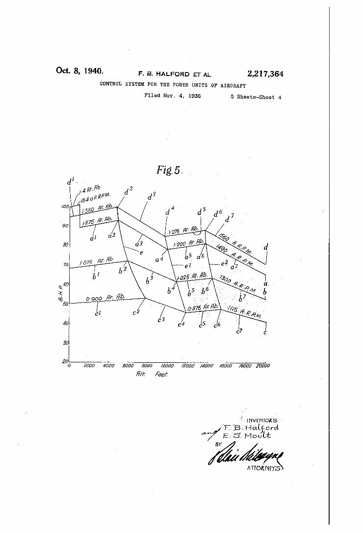
ure 5 which indicate, by way of example, out puts obtainable from a power unit having a con trol system similar to that described with refer ence to Figure 4. The four curves a, b, c and d are plotted with altitudes in feet above sea level as abscissae and, as ordinates, percentages of the take-01f output.
Considering the curve a, the pilot takes off at maximum boost pressure, say 1.4 atmospheres (absolute pressure), 100% power output and 1640 airscrew revolutions per minute. At approxi mately 1000 feet altitude the engine is throttled to a boost pressure of 1.275 atmospheres, the air screw speed being reduced to approximately 1490 revolutions per minute as indicated at the right hand end of the curve a. With this setting of the control mechanism the machine climbs with gradually increasing power, as shown by the part a1 of the curve a, the power increase being approximately 1.1% per 1000 feet altitude. When an altitude of approximately 4900 feet is reached (point 0.2) the throttle G is fully open and with further increase in altitude the boost pres sure falls of! below the initial climbing pressure of 1.275 atmospheres. The drop in power output, as indicated by the part a3 of the curve, con tinues up to the point a‘, that is to say approxi mately 9900 feet altitude, when the power reduc tion is so serious that a change in the super charger gear ratio is desirable. The change speed control device now automatically changes the gear ratio of the supercharger and at the same time the displacementv of the link U5 alters the datum of the boost control device E1 to give a boost pressure of 1.200 atmospheres. The out put of the engine now increases as shown by the part a5 of the curve a, the supercharger, in this high speed ratio, being capable of maintaining this boost pressure up to approximately 13,800 feet, corresponding to the point a6 on the curve a where full throttle is again attained. The out put will then again commence to‘ fall off, as shown by the part a" of the curve a, if the climb is continued to higher altitudes at the said en gine speed, namely 1490 revolutions per minute. Having attained his operational height the
pilot may throttle his engine to the maximum power permissible for cruising, as shown by the curve b. From this curve it will be seen that the limits for cruising are set at 1300 airscrew revolutions per minute and 1.075 atmospheres boost pressure at low altitudes. Within the cruis ing speed range therefore the power output in creases from approximately 68% of the take oil’ output, as shown by the part b1 of the curve b up to approximately 72% of the take-01f out put at 5900 feet, when the throttle is fully open,
9 this corresponding to the point b" on the curve I). For altitudes above 6000 feet the power output falls, as shown ‘by the part ;.b3 of the curve b until an altitude of 10,800 feet, that is to say the point I)‘ is attained. , The supercharger gear ratio is automatically
changed at the point 54 so that up to approxi mately 14,500 feet altitude the output again in creases as indicated by the part b5 of the curve b, the throttle being again fully open at the point b6 after which the output falls off as shown by the part b". After the gear change at the point b4 the boost pressure will be maintained at ap proximately 1.025 atmospheres up to the alti tude of 14,500 feet so that at the maximum cruising speed range the di?erence between the boost pressure at the high and low ratios of the supercharger is 0.05 atmosphere as opposed to the difference of 0.075 in boost pressure obtained within the climbing range indicated by the curve a. The curve 0 indicates variations in the power
output, and critical altitudes with reduced cruis ing speed, for example, as might be employed for economy in long range ?ying. From this curve it will be seen that the airscrew speed is approx imately 1115 revolutions per minute and at low altitudes the output increases slightly from 50% of the take-oif,-output at ground level, as shown by the part c1 of the curve, to approximately 54% of this output at, say, 7800 feet altitude (point 02) when the throttle is fully open. With increasing altitude the output falls off, as shown by the part c3 of the curve, until approximately 11,700 feet altitude is attained, this correspond ing to the point e4 on the curve. The gear ra tio of the supercharger is now changed automati cally and the output again rises slightly as shown by the part c5 of the curve up to an altitude of approximately 15,300 feet when the throttle is again fully open, this corresponding to the point e6 on the curve. For higher altitudes at this reduced cruising speed range the power output again falls o? as shown by the part c7 of the curve 0. It will be noted from this curve that the altitude at which the supercharger gear change takes place, i. e. the point e4 at 11,700 feet. is higher than the altitude (approximately 10,800) at which the gear change takes place at the higher cruising speed indicated by the curve b. Moreover, the di?erence in the boost pres sures at the two gear ratios of the supercharger at the reduced cruising speed, as indicated on the curve c, is 0.025 atmosphere, which is less than the difference above referred to, namely 0.05 atmosphere which is obtained by the gear
10
15
20
25
30
85
40
45
50
55
change at the higher cruising speed indicated on - the curve 5. In an emergency the pilot may ?y level for a
short period at high or “emergency” outputs as indicated by the curve d, the airscrew speed be ing approximately 1560 revolutions per minute. From this curve it will be seen that up to mod erate altitudes the output rises from approxi mately 94% to the take-01f output, i. e. 100%, as shown by the part d1 of the curve d, the permissible boost pressure being approximately 1.350 atmospheres. Beyond approximately 4800 feet, the throttle is fully open at a point corre sponding to the point d2 of the curve d, and the power output falls off as shown by the part d3 of the curve, until the point 114, that is .to say at an altitude of approximately 9700 feet. The gear ratio of the airscrew is now automatically changed and the output again rises as shown by
60
65
70
76
'15
25
30
35
40
45
50
55
60
75
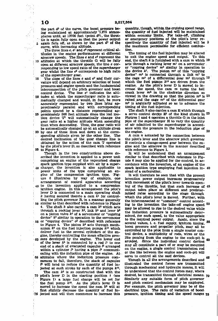
10 the part d5 of the curve, the boost.‘ pressure be ing maintained at approximately 61.275 atmos pheres until, at 13700 feet (point it“) , the throt tle is again fully open so that the power output again falls off, as shown by the part d‘I of the curve, with increasing altitudey. The three lines e, e1 and e2 represent critical a1
ti'tudes in the engine performances at different airscrew speeds. The lines e and 1:2 represent the altitudes at which the throttle G will be fully open at different airscrew speeds, the'line e cor responding to low speed ratio of the supercharger gear whilst the line e2 corresponds to high ratio of the supercharger gear. , The slope of the lines e and ea and their cur;
vature will depend on arbitrary selection'of boost pressures and engine'speeds and the fundamental interconnection of the pitch governor and boost control device. The line e1 indicates the alti tudes at which the supercharger ratio is auto matically changed and would, in fact, be more accurately represented by two lines lying ap proximately parallel and with corresponding points spaced by a distance representing ap proximately 500 feet altitude since the lost mo tion: device '1" will automatically change the gear ratio at a higher altitude when ascending than when descending. Thus, the gear ratio will be automatically changed up at an altitude given by one of these lines and down at the corre sponding altitude given by the other line. The desired inclination of the gear change line is obtained by the action of the cam T operated by the pilot’s lever D, as described with reference to Figure 4. Though in the two constructions above de
scribed the invention is .applied to a power unit comprising an engine of the vapourised charge spark ignition type supplied with air by a super charger, the invention is also applicable to power units of the type comprising an en gine of the compression ignition type. Fig ure 6 illustrates by way of example, one arrangement of control apparatus according to the invention applied to a compression ignition engine. In this arrangement the pilot’s lever‘ D is connected to a main operating shaft is having secured thereto a cam 71:1 for control ling the pitch governor B, in a manner generally similar to that described with reference to Figure 4. The shaft is also carries a cam k2 which acts through a rocking lever k3, link It‘ and lever k° on a piston valve is8 of a servomotor or “copying device” It" similar in operation to the servomotor or “copying device" 05 described with reference to Figure 4. ‘The piston It8 acts through mech anism k9 on the fuel injection pumps k“, which deliver fuel to the several cylinders of the en gine, thereby controlling the mean e?ective pres, sure developed by the engine. The lower end of the lever k? is connected by a rod 11 to one end of a stack of evacuated capsules F arranged within a cylinder 13 having a pipe 14 communi cating with the induction pipe of the engine. At altitudes where the induction pressure com mences to fall, therefore, the stack of capsules I? will tend to reduce the quantity of fuel in jected at each stroke by each of the pumps km. The cam k2 is so constructed that with the
pilot’s lever D in the starting position I (see Figure l) a large fuel charge will be set for the fuel pump km. As the pilot’s lever D is moved to increase the speed the cam is’ will at ?rst slightly decrease the quantity of fuel in‘ jected and will then commence to increase this
‘to suit the engine speed and output.‘
2,217,364 . quantity, though, .withinthe cruising speed range, the quantity of fuel injected will be maintained within economy ‘limits. For take-off, climbing or emergency positions of the pilot’s lever re- spectively the quantity of fuel injected will be the maximum permissible for efllcient combus tion. a
The timing of the fuel injection may be altered To this
end, the ,shaft is is furnished with a cam m which acts through a rocking lever m1 on a servomotor or “copying device’? m5 similar in operation to the device It". The piston m“ of this “copying device" m5 is connected through a link m7 to the cage m8 of a differential gear m" through which the fuel pumps k10 are driven from the engine. As the pilot's lever D is moved to in crease the speed, the cam m turns the bell crank lever 11!-3 in the clockwise direction as viewed in the drawing so that the piston m“, is \ raised_and the cage m’ of the differential gear m’ is angularly adjusted so as to advance the timing of the fuel injection. The shaft is also carries a cam E which through
a servo control devic E1 of the kind shown in Figures land 4 operates a throttle G in the inlet pipe of the supercharger H to vary the quantity of air admitted to the supercharger in accord ance with the pressure in the induction pipe of the engine. A cam 12 actuated by the connection between.
the pilot’s lever and the airscrew pitch governor B controls a change-speed gear between the en glue and the airscrew in the manner described with reference to Figure 1.
It will be understood that an arrangement, similar to that described with reference to Fig ude 6 may also be applied ‘for the control, in ac cordance with the invention, of an engine of the spark ignition type employing fuel injection in stead of a carburettor.
It will therefore be seen that with the present invention power output increases progressively with movement of the pilot’s lever towards open ing of the throttle, but that such increase of output takes place at different and predeter— mined rates according to the stage through which the pilot’s lever is moved. Further, with the interconnected or “common” control accord ing to the invention the take-off engine speed may be allowed to rise to the desired value while the induction pressure is automatically deter
10
25
35
40
45
50
mined, for each speed, to the value appropriate ' to the required power output. Again, since the
, several values, 1. e. fuel supply, ignition timing, boost pressure and propeller pitch, may all be controlled by the pilot from a single master con trol device, a multiplicity of rods, wires or the like passing from the. engine to the cock-pit is avoided. Since the individual control devices
55
may all constitute a part of or may be mounted . on the engine, a single control transmission rod or the like between the engine and cock-pit will serve to controlvall the said devices. ' Though in all the arrangements described and
illustrated the control forces are transmitted through mechanical and hydraulic means, it will be understood that the control forces may, where desired, be transmitted through electrical means. Similarly any suitable form of pitch governor and pitch control mechanism may be employed. For example, the pitch'govemor may be of the electrical type. The ratio of variation of boost
10'
pressure, ignition timing and the speed ranges 75

10
15
20
30
35
40
45
50
55
60
65
75
2,217,864 over which such variations take place may vary with different power units. What we claim as our invention and desire
to secure by Letters Patent is: _ 1. An aircraft power unit comprising in com
bination an internal combustion engine, 9. var iable pitch airscrew driven thereby, a governor controlling the airscrew pitch ‘so as to govern the engine speed, a regulating device responsive to the induction pressure of the engine and adapted _to control the said pressure and the fuel input to the engine, means for varying the ratio of fuel and air supplied to the engine, a_ master control device under the control of the pilot for simultaneously eifecting the appropriate adjust ments of engine speed and torque required for various conditions of ?ight, and interconnecting means between the master control device, the pitch governor, the regulating device and the means for varying the fuel/air ratio.
2. An aircraft power unit comprising in com bination an internal combustion engine, a vari able pitch airscrew driven thereby, a governor controlling the airscrew pitch so as to govern the engine speed, a throttle, a regulating device responsive to the induction pressure of the en gine and adapted to move the said throttle to control the said pressure and the fuel input to the engine, a master control device under the control of the pilot for simultaneously effecting the appropriate adjustments of engine speed and torque required for various conditions of ?ight, interconnecting means between the master con trol device, the regulating device, the pitch gov ernor and the throttle and means for permitting movement of the master control device after the throttle has been moved to its fully open posi tion.
3. An aircraft power unit comprising in com bination an internal combustion engine, a vari able pitch airscrew driven thereby, a governor controlling the airscrew pitch so as to govern the engine speed, a regulating device responsive to the induction pressure of the engine and adapted to control the said pressure and the fuel input to the engine, a master control device un der the control of the pilot for simultaneously effecting the appropriate adjustments of engine speed and torque required for various conditions of ?ight, interconnecting means between the master control device, the pitch governor and the regulating device, and means whereby movement of the master control device from a starting po sition through a “?rst stage" and tending to in crease the input to the engine is at ?rst substan tially ineffective on the regulating device and pitch governor, whereas the continued movement of the master control device through this stage in?uences the regulating device and the governor towards an increase in the engine speed, move ment of the master control device through a “second stage" causes the regulating device to increase the induction pressure with simulta neous but relatively small increase in the en gine speed and movement of the master control device through a “third stage" causes the engine speed to be increased with little, if any, change in the induction pressure.
4. An aircraft vpower unit comprising in com bination an ‘internal combustion engine of the spark ignition type, a variable pitch airscrew driven thereby, a governor controlling the air screw pitch so as to govern the engine speed, a regulating device responsive to the induction pressure of the engine and adapted to control the
11 said pressure and the fuel input to the engine, means for regulating the timing vof the ignition, a master control device under the control of the pilot for simultaneously effecting the appropriate adjustments of engine vspeed and torque required for various conditions of ?ight, interconnecting means between the master control device, the pitch governor, the pressure regulating device and the means for regulating the timing of the ignition, and means whereby movement 0 of the master control device from a starting position through a “?rst stage” and tending to increase the input to the engine is at first substantially , ineffective on the pressure regulating device, the pitch governor and the ignition timing regulating device, whereas continued movement of the mas ter control device through this stage actuates the pressure regulating device and the governor to wards an increase in the engine speed and at the same time rapidly advances the timing of the ignition, movement of the master control device through a _“second stage" causes the rate of igni tion advance to be decreased and then causes the ignition to be retarded and the pressure regulat ing device to increase the induction pressure with a simultaneous but relatively small increase of the engine speed and movement of the master control device through a “third stage” causes the engine speed to be increased with little, if any, change in the induction pressure and ignition timing.
5. An aircraft power unit comprising in combi nation an internal combustion engine, a vari able pitch airscrew driven thereby, a‘ governor controlling the airscrew pitch so as to govern ‘the engine speed, a regulating device responsive to the induction pressure of the engine and adapted to control the said pressure andthe fuel input to the engine, means for regulating the ratio of fuel and air supplied to the engine, a master control device under the control of the pilot for simultaneously effecting the appropriate adjustment of engine speed and torque required for various conditions of ?ight, interconnecting means between the master control device, the pitch governor, the pressure regulating device and the fuel/air ratio regulating means, and means whereby movement of the master control device from a starting position through a “first stage” and tending to increase the input to the engine is at ?rst substantially ineffective on the pressure regulating device and the pitch governor while causing the ratio of fuel to air to be in creased for starting and slow running speeds, whereas continued movement of the master con trol device through this stage causes the ratio of
. fuel to air to be decreased and actuates the boost pressure regulating device and governor towards an increase in engine speed, movement of the master control device through a “second stage” causes the ratio of fuel to air to be gradually in creased, and increases the induction pressure with simultaneous but relatively small increase of the engine speed, and movement of the master con trol device through a “third stage” causes the ratio of fuel to air to be increased more rapidly and the engine speed to be increased with little, if any, change in the induction pressure.
6. An aircraft power unit comprising in com bination an internal combustion engine of the spark ignition type, a variable pitch airscrew driven thereby, a governor controlling the air screw pitch so as to govern the engine speed, a regulating device responsive to the induction pres sure of the engine and adapted to control the said
20
25
35
40
45
50
55
60
65
70
75

25
‘so
35
45
~50
55
70
75
i
1 2 ,
pressure and the fuel input to the engine, means for varying thetiming of the ignition, means for regulating the ratio, of fuel and air supplied to the engine, and a master control device under the control of the pilot for simultaneously effecting the appropriate adjustments of engine speed and torque required for various conditions of flight,’
- interconnecting means between the master con trol device, the pitch governor,_,the regulating device. the ignition control and the means for regulating the fuel/air ratio, and means separate from the master control device for simultaneous 1y advancing the ignition timing and decreasing the ratio of fuel to air supplied to the engine.
'7. An aircraft power unit comprising in com bination an internal combustion engine of the spark ignition type, a variable pitch airscrew driven thereby, a governor controlling the air screw pitch so as to govern the engine speed, a regulating device responsive to the induction pressure of the engine and adapted to control the said pressure and the fuel input to the en gine, means for regulating the ignition timing, means for regulating the timing of the ignition automatically in accordance with the altitude, a master control device under vcontrol of the pilot for simultaneously effecting the appropriate ad justments of engine speed and torque required for various conditions of ?ight, and interconnecting means between the master control device, the pitch governor, the pressure regulating device and the 'means for regulating the ignition timing.
8. An aircraft power unit comprising in com bination an internal combustion engine, a varia- - ble pitch airscrew driven thereby, a governor con trolling the airscrew pitch so as to govern the engine speed, a supercharger for supplying air to the engine, a change speed gear through which the supercharger is driven by the engine, a reg ulating device responsive to the induction pres sure of the engine and adapted to control the said pressure and input to the engine, a change speed control device whereby the ratio of the change speed gear is automatically changed at predetermined altitudes, a master control device under the control of the pilot for simultaneously effecting the appropriate adjustments of engine speed and torque required for various conditions of ?ight, and interconnecting means between the master control device, the pitch governor, the pressure regulating device and the change speed control device.
9. An aircraft power unit comprising in com-, bination an internal combustion engine, a varia ble pitch airscrew driven thereby, a governor con trolling the airscrew pitch so as to govern the engine speed, a supercharger for supplying air to the engine, a change speed gear through which the supercharger is driven 'from the‘ engine, a change speed control device whereby the ratio of
_ the said gear is automatically changed at prede termined altitudes, a regulating device responsive to the induction pressure of the engine and adapted to control the said pressure and the fuel input to the engine, means whereby the pressure regulating device is controlled in accordance with the gear ratio set by the change speed gear con trol device, a master control device under the control of the pilot for simultaneously effecting the appropriate adjustments of engine speed and torque required for various conditions of ?ight, and interconnecting means between the master control device, the pitch governor and the pres sure regulating device.
10. An aircraft power unit comprising in com
2,217,864 _ , , I I
_ bination an internal combustion engine, a varia ble pitch airscrew driven thereby, a governor con trolling the alrscrew pitch so as to govern the ‘engine speed,ya supercharger for supplying air to the engine, a change speed gear through which the supercharger, is driven from the engine, a change speed control device whereby the ratio of the said gear is automatically changed at pre determined altitudes, a regulating device respon sive to the induction pressure of the engine and adapted to control the said pressure and the fuel ‘input to the engine, a master control device un der the control of the pilot for simultaneously effecting the appropriate adjustments of engine speed and torque required for various conditions of ?ight, interconnecting means between ' the master control device, the pitch governor and the pressure regulating device, and means whereby the altitude at which the ratio of the gear is changed when the craft is ascending is caused to differ from the altitude at which the ratio of the gear is changed when the craft is descending.
11. _An aircraft power unit ‘comprising in com bination an internal combustion engine, a varia-, ble pitch airscrew driven thereby, a governor con trolling the. airscrew pitch so as to govern the engine speed, a supercharger driven by the engine and supplying -”air thereto, a change speed gear through which the supercharger is driven from the engine, a change speed control device where by the ratio of the said gear is automatically
10
15
20
25
39. changed at predetermined altitudes, a regulating ' device responsive to the induction pressure of the . engine and ‘adapted to control the said pressure and the fuel input to the engine, a master control device under the control of the pilot for simul taneously effecting the appropriate adjustments of engine speed and torque required for various conditions of ?ight, interconnecting means be tween the master control device and the change speed gear control device, and overriding control means whereby the ratio of the change speed gearcan be altered by the pilot independently of the automatically operating change speed con trol device. . ' -
12. An aircraft power unit comprising in com bination an internal combustion engine, a varia ble pitch airscrew, a change speed gear through which the airscrew is driven from the ‘engine, a change speed control device for altering the ratio of the change speed gear, a governor controlling the airscrew pitch. so as to govern the engine speed, a regulating device responsive to the in duction pressure of the engine and adapted to control the said pressure and the fuel input to the engine, a master control device under the control of the pilot for simultaneously effecting the appropriate adjustments of engine“speed and torquelrequired for various conditions of ?ight, and interconnecting meansbetween the master control device, the pitch governor,v the change speed control device and the regulating device,
85
40
45
50
65
60
and means whereby movement of the master . control device to increase the engine speed be yond a given value causes the ratio of the said gear to be changed so as to increase the ratio of the airscrew speed with respect to the engine speed.v L _
13. An aircraft power unit comprising in combination an internal combustion engine, a variable pitch airscrew driven thereby, a gov ernor controlling the airscrew pitch so as to govern the engine speed, a regulating device re sponsive to the induction pressure of the engine and adapted to control the said pressure and the
65
70
75

20
2,217,804 ,
fuel input to the engine, a master control device under the control of the pilot for simultaneously effecting the appropriate adjustments of engine speed and torque required for various conditions of ?ight, interconnecting means between the master control device, the pitch governor, and the regulating device, and overriding means whereby in certain positions the master control device positively sets the airscrew pitch irrespec tive of the automatic pitch control.
14. An aircraft power unit comprising in com bination an internal combustion engine, a varia ble pitch airscrew driven thereby, a governor controlling the airscrew pitch so as to govern the engine speed, a regulating device responsive ' to the induction pressure of the engine and adapted to control the said pressure and the fuel input to the engine, a master control device un der the control of the pilot for simultaneously eifecting the appropriate adjustments of engine speed and torque required for various conditions of ?ight, interconnecting means between the master control device, the pitch governor and the
13 regulating device, and means whereby line air screw pitch is maintained by the master control device while this is in its starting position irre spective of the automatic pitch control.
15. An aircraft power unit comprising in com bination an internal combustion engine, a varia ble pitch airscrew driven thereby, a governor controlling the airscrew pitch so as to govern the engine speed, a regulating device responsive to the induction pressure of the engine and adapted to control the said pressure and the fuel input to the engine, a master control device under the control of the pilot for simultaneously e?ecting the appropriate adjustments of engine speed and torque required for various conditions of ?ight, interconnecting means between the master control device, the pitch governor and the reg ulating device, and means whereby a coarse air screw pitch is set irrespective oi‘ the automatic pitch control by movement of the master control device out of its normal range of movement.
FRANK BERNARDHALFORD. ERIC STANLEY MOULT.
15
20