Embed Size (px)
Citation preview

CHAPTER 6
AIRCRAFT POWER PLANTS
INTRODUCTION
All naval aircraft are engine driven. The earlyengines were all reciprocating engines. Today, almostall are jet propulsion engines. Therefore, this chaptercovers only jet propulsion engines.
The jet propulsion principle is the basic concept forthe gas turbine engine. This principle is not a newconcept. Sea creatures use jet propulsion to propelthemselves through the water. The Egyptians built thefirst reaction engine around 250 BC. Between 1700 and1930, technical achievements in engineering,manufacturing, and metallurgy made the reactionprinciple applicable to the development of the gasturbine engine for jet propulsion. In 1939, the Germansflew the first aircraft powered by a gas turbine engine,followed by the British in 1941, and the Americans in1942. During World War II, Germany was the onlynation to fly a gas turbine-propelled aircraft in actualcombat.
There are four types of jet propulsion engines: therocket, the ramjet, the pulsejet, and the gas turbineengine. Of these, the gas turbine engine powers almostall naval aircraft. There are four types of gas turbineengines: the turbojet, the turbofan, the turboprop, andthe turboshaft. The turbojet and turbofan engines usethrust directly. The turboprop and turboshaft enginesuse thrust to deliver torque (turning power) to anairplane propeller or a helicopter rotor. Regardless ofthe type, the purpose of an engine is to develop thrust.This chapter will give you basic information on jetpropulsion engines.
JET PROPULSION ENGINES
LEARNING OBJECTIVE : Recognize thebasic operating principles for the four types ofjet propulsion engines, and identify thecomponents and functions of each type ofengine.
A jet propulsion engine projects a column of air tothe rear at extremely high speeds. The resulting thrustpushes the aircraft in the opposite (or forward)direction. Jet propulsion engines are grouped into fourmain types:
1. Rocket. These are jet propulsion systems thatdo not use atmospheric air.
2. Ramjet. The ramjet operates as a continuousthermal duct or athodyd.
3. Pulsejet. The pulsejet operates as anintermittent impulse duct.
4. Gas turbine. The gas turbine engine operates asa continuous turbine-compressor unit.
ROCKET ENGINES
The rocket uses a form of jet propulsion that differsin basic ways from thermal gas turbine systems. Therocket does not draw air from the outside to fuel thecombustion process. It carries with it both the fuel andthe oxidizer for combustion. This is a disadvantage foratmospheric flight, but it is the only way at present tofuel flight outside the earth's atmosphere. The rocket isa true jet reaction unit. A brief examination of itsfunctions clarifies the reaction principle by which allthermal jet units operate.
If you burn a hydrocarbon (compound containingonly hydrogen and carbon) in a closed container (fig.6-1), the heat of the burning fuel is released, causing thetrapped gases to expand rapidly. Because the containerhas a closed volume, the temperature and pressure risesand is uniformly distributed (balanced) in all directions.Since the force of the rising pressure cannot be releasedand is balanced, the container does not move.
6-1
Figure 6-1.—Combustion in a closed container.

When you burn fuel in a container that has anopening (or nozzle) at one end, expanding gases rushout of the nozzle at a high velocity, as shown in figure6-2. Releasing internal pressure at the nozzle end of thecontainer leaves an unbalanced pressure at the otherend.The released pressure moves the container inthe direction opposite to that of the escaping gases.This is the basic operating principle for all jetengines. Obviously, propulsion depends solely oninternal conditions. The container does not "pushagainst" external air. In fact, a complete vacuum wouldproduce even greater force.
The jet propulsion engine operates like a toyballoon. Newton's third law of motion explains thisoperation. This law states "for every acting force thereis an equal and opposite reacting force." Inflate aballoon. The air pressure inside the balloon, which isstretching the skin, is greater than the pressure outsidethe balloon. If the stem is tied closed, the inside airpushes in all directions and the balloon will not move.Place the balloon in a vacuum and release the stem. Theescaping air has nothing to push against, but the balloonwill move in a direction away from the stem, just as itdoes in a normal atmosphere.
Releasing the stem removes a section of skin on theside of the balloon against which the air has beenpushing. On the side directly opposite the stem,however, the air continues to push on an equal area ofskin. The continued push of air on this area causes theballoon to move in the direction away from the stem.
Theacting forcethat Newton's third law refers to isthe acceleration of the escaping air from the rear of the
balloon. The reaction to this acceleration is a force inthe opposite direction. In addition, the amount of forceacting on the balloon is the product of the mass of airbeing accelerated times the acceleration of that air.Since the forces always occur in pairs, we can say that ifa certain force is needed to accelerate a mass rearward,the reaction to this force is thrust in the oppositedirection (force = thrust, as shown in figure 6-3).
RAMJET ENGINES
The ramjet is often described as a flying stovepipe.It is the simplest of all power plants that useatmospheric air to support combustion.
A ramjet is an appropriately shaped duct, tapered atboth ends, in which fuel is injected and burned at aconstant pressure, as shown in figure 6-4. Except for thepossibility of fuel pumps or other accessories, there areno moving parts.
The air inlet diffuser of the ramjet engine isdesigned to convert the velocity energy of the enteringair into static pressure. This is commonly known asram. During the inlet process, fuel is injected into theairstream, where it is well mixed with the air so that itwill burn readily. At about the point of highest pressurein the engine, combustion is initiated and the fuel-airmixture is burned. The gases of combustion and theheated air expand, thus air is ejected from the exitnozzle at a much higher velocity than it had when itentered the engine. This change in the velocity of theentering and departing air results in the thrust.
PULSEJET ENGINES
The pulsejet engine is a member of the athodyd(aero-thermodynamic-duct) family, since it does nothave a compressor or a turbine.
The pulsejet engine differs from the ramjet in thatthe inlet duct is sealed with a disc that incorporatesflapper valves. The purpose of the flapper valves is toprovide the required air intake system, seal thehigh-pressure gases in the combustion chamber, andprevent their escape out the inlet duct during thecombustion cycle. A pulsejet engine consistsessentially of a diffuser, an air valve bank (automatic or
6-2
Figure 6-2.—Principle of jet propulsion.

6-3
Figure 6-3.—Balloon as a jet engine.
Figure 6-4.—The ramjet engine.

mechanical), a combustion chamber, and a tailpipe orexit nozzle, as shown in figure 6-5.
While the ramjet will deliver no static thrust, thepulsejet engine can produce static thrust. However, thethrust developed under static conditions is not sufficientto enable a pulsejet aircraft or guided missile to take offunder its own power, at least not on conventionalrunways. Consequently, missiles or other devicespowered by pulsejet engines must be boosted toself-sustaining flight speeds by catapults or rockets.
Possible applications for the pulsejet engine, otherthan for powering pilotless military weapons, includeflight research, powering helicopters by attaching smallpulsejet engines to the rotor blade tips, and emergencypower plants for small aircraft and gliders.
GAS TURBINE ENGINES
As stated earlier, there are four types of gas turbineengines: turbojet, turboprop, turboshaft, and turbofan.Each of these engines is briefly discussed in thefollowing paragraphs.
Turbojet Engines
There are over 40 different Navy models of theturbojet engine. The A-6 and T-2 are examples ofaircraft that use this direct thrust engine. The turbojetengine consists of five major components: an inletduct, a compressor, a combustion chamber (orchambers), a turbine (or turbines), and an exhaust coneassembly, as shown in figure 6-6.
INLET DUCT .—The inlet duct is an opening inthe front of the aircraft that allows outside (ambient) airto enter the engine. The compressor compresses theincoming air and delivers it to the combustion (orburner) section. In the combustion chamber, fuel issprayed into and mixed with the compressed air. Anigniter then ignites the fuel-air mixture. The burningmixture continues to burn in the presence of the properfuel-air mixture. The fuel-air mixture burns at arelatively constant pressure. Only about 25 percent ofthe air is used in the combustion process. The rest of theair (75 percent) is mixed with the combustion products(exhaust) for cooling before the gases enter the turbinesection.
The turbine section extracts and uses a majorportion of the energy in the gas stream to turn thecompressor and accessories. After leaving the turbine,the remaining pressure forces the hot gases through theengine exhaust duct at very high speeds. The air that
6-4
Figure 6-5.—The pulsejet engine.
Figure 6-6.—Five major components of the turbojet.

entered the inlet is now expelled at a much higher speedthan when it entered. This causes the engine thrust.
COMPRESSOR.—The axial-flow compressor ismade up of a series of rotating blades and a row ofstationary stator vanes, as shown in figure 6-7. A row ofrotating blades and stator vanes is called a stage. Theentire compressor is made up of a series of alternatingrotor blade and stator vane stages.
You recall that the compressor provideshigh-pressure air to the combustion chamber (orchambers). The compressor delivers outside air(ambient) to the inlet section and passes this air throughthe inlet guide vanes. In turn, the inlet guide vanesdeflect the air in the direction of compressor rotation.The rotating blades arrest the airflow and pass it to a setof stationary stator vanes. The air is again deflected andpicked up by another set of rotating blades, and so onthrough the compressor. The pressure of the airincreases each time it passes through a set of rotors andstators because the areas of the rotors and stators getsmaller, as shown in figure 6-8.
One development in the axial-flow engine is thesplit spoolcompressor. This compressor (fig. 6-9) usestwo rotors of nine and seven stages, respectively. Anassigned wheel drives each rotor of the axial three-stage
turbine assembly. This configuration makes possiblehigh compressor pressure ratios, which are necessaryfor efficient high-altitude operations.
Another development was necessary to eliminatecompressor stall in turbojet engines. The axialcompressor, especially with fixed blading, was subjectto stalling. Compressor stall was normally caused by abreakdown of the airflow through a few stages of thecompressor. Compressor stall could progress until thecomplete unit stalled.
There are two methods to eliminate compressorstall. The compressor bleed-air system and the variablevane system. The compressor bleed-air system bleedsoff approximately 10 percent of the front compressordischarge air. It reduces the amount of air available tothe rear compressor. This provides a surge-freeoperation throughout the critical speeds of the engine.The variable vane system changes the position of theinlet guide vanes and the stator vanes to avoidcompressor stall. This action maintains the velocity ofthe air (and the angle at which it strikes the blades)within acceptable limits for low airflow conditions. Italso permits high airflow with a minimum ofrestriction.
6-5
Figure 6-7.—Stator and rotor components of an axial-flowcompressor.
Figure 6-8.—Five-stage compressor.
Figure 6-9.—Dual rotor turbine for split spool compressor.

COMBUSTION CHAMBER .—The efficiencyand performance of a turbine power unit depend on thetype of combustion system used. The basicrequirements for a satisfactory system are a high rate ofburning, minimum pressure drop, small bulk, and lightweight. The system must be consistent in operationover a wide range of loads and altitudes, with notendency to flood with fuel or suffercombustionblowout. Combustion blowout is a flame failure, and itis primarily a problem in high-altitude operation.Starting must be easy and positive, both on the groundand in the air. Combustion must be complete to avoidformation of carbon deposits.
Fuel enters the front of the burner as an atomizedspray or in a prevaporized form. Air flows in around thefuel nozzle and through the first row of combustion airholes in the liner. Air near the burner nozzle stays closeto the front liner wall for cooling and cleaningpurposes. Air entering through opposing liner holesmixes rapidly with the fuel to form a combustiblemixture. Air entering the forward section of the linerrecirculates and moves upstream against the fuel spray.During combustion, this action permits rapid mixingand prevents flame blowout by forming a low-velocity
stabilization zone. This zone acts as a continuous pilotfor the rest of the burner. Air entering the downstreampart of the liner provides the correct mixture forcombustion. This air also creates the intense turbulencenecessary for mixing the fuel and air and fortransferring energy from the burned to the unburnedgases.
Since an engine usually has two igniter plugs, crossignition tubes are necessary in the can and can-annulartypes of burners. These tubes allow burning to start inthe other cans or inner liners. Axial-flow engines useeither an annular or the can-annular (fig. 6-10) type ofcombustion chamber. The igniter plug is usuallylocated in the upstream reverse flow region of theburner. After ignition, the flame quickly spreads to theprimary (combustion) zone. This zone contains thecorrect proportion of air to completely burn the fuel. Ifall the air flowing through the engine were mixed withthe fuel at this point, the mixture would be outside thecombustion limits for the fuel normally used.Therefore, only about one-third to one-half of the air isallowed to enter the combustion zone of the burner.About 25 percent of the air actually takes part in thecombustion process.
6-6
Figure 6-10.—Can-annular combustion chamber components and arrangements.

Gases that result from the combustion process havetemperatures of approximately 3,500<F (1,900<C).Before entering the turbine, these gases must be cooledto about half this value. The design of the turbine andthe materials used in its makeup determine thetemperature to which the gases must be cooled.Secondary air, which enters through a set of relativelylarge holes located toward the rear of the liner, dilutesand cools the hot gases. The liner must also beprotected from the high temperatures of combustion.This is usually done by cool air introduced at severaldifferent places along the liner. The cool air forms aninsulating blanket between the hot gases and the metalwalls, as shown in figure 6-11.
TURBINE .—The turbine assembly drives thecompressor and accessories by extracting some of theenergy and pressure from the combustion gases. In atypical jet engine, about 75 percent of the powerproduced internally is used to drive the compressor.
The remaining 25 percent produces the necessarythrust.
The turbine consists of a nozzle assembly and arotating blade assembly. The hot gases from thecombustion chamber flow through the turbine nozzleassembly and are directed against the rotating turbinedisk blades. The rotating blade assembly (turbine rotor)is made up of a steel shaft and disk. High-temperaturealloy blades are locked into grooves cut in the peripheryof the disk. The entire turbine rotor is statically anddynamically balanced. In some units, the turbinecompressor rotors are mounted on the same shaft. Inother units they are mounted on separate shafts that areconnected during assembly.
The nozzle assembly consists of the nozzle guidevanes and the stator ring/shroud ring, as shown in figure6-12. The guide vanes are made up of high-temperaturealloy. They are fitted into or welded to the statorring/shroud.
6-7
Figure 6-11.—Airflow through a can-annular chamber.
Figure 6-12.—Turbine rotor and nozzle.

EXHAUST CONE ASSEMBLY .—The exhaustcone (fig. 6-13), attached to the rear of the turbineassembly, is a tapered, cylinder-shaped outlet for the
gases. The cone eliminates turbulence in the emergingjet, thereby giving maximum velocity.
The inner cone is usually attached to the outer coneby streamlined vanes called brace assemblies. Theexhaust cone itself is usually made of stainless steelsheets, reinforced at each end with stainless steelflanges. As much heat energy as possible is kept withinthe exhaust cone. A covering of layers of aluminum foilor other material acts as insulation for the cone.
Turboprop Engines
There are numerous models of the turbopropengine. The P-3 and E-2 aircraft are examples ofaircraft that use turboprop engines.
The turboprop engine was developed to provide thepower requirements for aircraft of greater size, carryingcapacity, range, and speed. The turboprop engine iscapable of developing 2 1/2 horsepower per pound ofweight.
The turboprop converts most of its gas-energy intomechanical power to drive the compressor, accessories,and a propeller. The additional turbine stages needed todrive the extra load of a propeller create thelow-pressure, low-velocity gas stream. A small amountof jet thrust is obtained from this gas stream.
The turboprop engine (fig. 6-14) consists of threemajor assemblies: the power section, the torquemeterassembly, and the reduction gear assembly. Thepropeller assembly mounts on the reduction gearassembly to provide aircraft thrust.
6-8
Figure 6-13.—Typical exhaust cone assembly.
Figure 6-14.—T56 turboprop engine.

POWER SECTION.—The power sectionconsists of an axial-flow compressor, a combustionchamber, a multi-stage turbine, and an exhaust section.The last two stages of the turbine are used to drive thepropeller using the torquemeter assembly and thereduction gear assembly.
TORQUEMETER ASSEMBLY .—The torque-meter assembly electronically measures the torsionaldeflection (twist). Torsional deflection occurs in thepower transmitting shaft that connects the powersection to the reduction gear assembly. This torsionaldeflection is recorded as horsepower.
REDUCTION GEAR ASSEMBLY .—Thereduction gear assembly reduces the engine rpm withinthe range of efficient propeller rpm. The ratio on someinstallations is as high as 12 or 13 to 1. This largereduction ratio is necessary because the gas turbinemust operate at a very high rpm to produce power
efficiently. This engine operates at a constant rpm. Thepropeller blade angle changes for an increase ordecrease in power while the engine rpm remains thesame.
The typical propeller assembly for a turbopropengine (fig. 6-15) consists of a front and rear spinnerassembly, a hub-mounted bulkhead assembly, the domeassembly, four blades, an afterbody fairing assembly,and a propeller control assembly. The propellerassembly converts the power developed by the engineinto thrust as efficiently as possible under all operatingconditions.
Turboshaft Engines
There are many different models of this type ofengine. The H-46 and H-53 helicopters are examples ofaircraft that use this engine.
6-9
Figure 6-15.—Propeller assembly and associated parts.

6-10
Figure 6-16.—Turboshaft gas turbine engine.
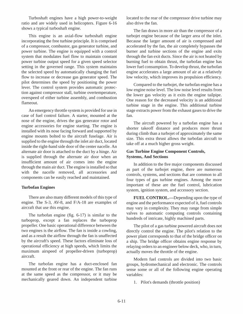
Turboshaft engines have a high power-to-weightratio and are widely used in helicopters. Figure 6-16shows a typical turboshaft engine.
This engine is an axial-flow turboshaft engineincorporating the free turbine principle. It is comprisedof a compressor, combustor, gas generator turbine, andpower turbine. The engine is equipped with a controlsystem that modulates fuel flow to maintain constantpower turbine output speed for a given speed selectorsetting in the governed range. This system maintainsthe selected speed by automatically changing the fuelflow to increase or decrease gas generator speed. Thepilot determines the speed by positioning the powerlever. The control system provides automatic protec-tion against compressor stall, turbine overtemperature,overspeed of either turbine assembly, and combustionflameout.
An emergency throttle system is provided for use incase of fuel control failure. A starter, mounted at thenose of the engine, drives the gas generator rotor andengine accessories for engine starting. The engine isinstalled with its nose facing forward and supported byengine mounts bolted to the aircraft fuselage. Air issupplied to the engine through the inlet air duct, locatedinside the right-hand side door of the center nacelle. Analternate air door is attached to the duct by a hinge. Airis supplied through the alternate air door when aninsufficient amount of air comes into the enginethrough the main air duct. The engine is installed so thatwith the nacelle removed, all accessories andcomponents can be easily reached and maintained.
Turbofan Engines
There are also many different models of this type ofengine. The S-3, AV-8, and F/A-18 are examples ofaircraft that use this engine.
The turbofan engine (fig. 6-17) is similar to theturboprop, except a fan replaces the turboproppropeller. One basic operational difference between thetwo engines is the airflow. The fan is inside a cowling,and as a result the airflow through the fan is unaffectedby the aircraft's speed. These factors eliminate loss ofoperational efficiency at high speeds, which limits themaximum airspeed of propeller-driven (turboprop)aircraft.
The turbofan engine has a duct-enclosed fanmounted at the front or rear of the engine. The fan runsat the same speed as the compressor, or it may bemechanically geared down. An independent turbine
located to the rear of the compressor drive turbine mayalso drive the fan.
The fan draws in more air than the compressor of aturbojet engine because of the larger area of the inlet.Because the larger amount of air is compressed andaccelerated by the fan, the air completely bypasses theburner and turbine sections of the engine and exitsthrough the fan exit ducts. Since the air is not heated byburning fuel to obtain thrust, the turbofan engine haslower fuel consumption. To develop thrust, the turbofanengine accelerates a large amount of air at a relativelylow velocity, which improves its propulsion efficiency.
Compared to the turbojet, the turbofan engine has alow engine noise level. The low noise level results fromthe lower gas velocity as it exits the engine tailpipe.One reason for the decreased velocity is an additionalturbine stage in the engine. This additional turbinestage extracts power from the exhaust gases to drive thefan.
The aircraft powered by a turbofan engine has ashorter takeoff distance and produces more thrustduring climb than a turbojet of approximately the samesize. This extra thrust allows the turbofan aircraft totake off at a much higher gross weight.
Gas Turbine Engine Component Controls,Systems, And Sections
In addition to the five major components discussedas part of the turbojet engine, there are numerouscontrols, systems, and sections that are common to allfour types of gas turbine engines. Among the moreimportant of these are the fuel control, lubricationsystem, ignition system, and accessory section.
FUEL CONTROL.— Depending upon the type ofengine and the performance expected of it, fuel controlsmay vary in complexity. They may range from simplevalves to automatic computing controls containinghundreds of intricate, highly machined parts.
The pilot of a gas turbine powered aircraft does notdirectly control the engine. The pilot's relation to thepower plant corresponds to that of the bridge officer ona ship. The bridge officer obtains engine response byrelaying orders to an engineer below deck, who, in turn,actually moves the throttle of the engine.
Modern fuel controls are divided into two basicgroups, hydromechanical and electronic. The controlssense some or all of the following engine operatingvariables:
1. Pilot's demands (throttle position)
6-11

6-12
Figure 6-17.—Turbofan engine.

2. Compressor inlet temperature
3. Compressor discharge pressure
4. Burner pressure
5. Compressor inlet pressure
6. RPM
7. Turbine temperature
The more sophisticated fuel controls sense even moreoperating variables.
The fuel control is theheart of the gas turbineengine fuel system. This complex device schedules fuelflow to the engine combustion chamber. Itautomatically provides fuel flow as dictated by theoperating conditions of the engine (temperature,pressures, altitude, throttle position, etc.).
The fuel control combines the inputs of throttleposition, compressor discharge pressure, compressorinlet temperature, and engine speed to produce the fuelflow to operate the engine. The fuel control governs theengine speed by controlling fuel flow. Fuel flowvariations are limited to ensure fast stall-freeacceleration and deceleration. During throttle bursts,the fuel control also postpones the initiation of theafterburner operation (if installed) to achieve the fastestpossible acceleration.
LUBRICATION SYSTEM .—The oil lubricationsystems of modern gas turbine engines vary in designand plumbing. However, most systems have units thatperform similar functions. In a majority of cases, apressure pump or system furnishes oil to lubricate andcool several parts of the engine. A scavenging systemreturns the oil to the tank for reuse. Overheating is aproblem in gas turbine engines. Overheating is moresevere after the engine stops than while it is running.Oil flow, which normally cools the bearings, stops. Theheat stored in the turbine wheel now raises thetemperature of the bearings much higher than when theengine was running. The oil moves heat away fromthese bearings to prevent overheating. Most systemsinclude a heat exchanger to cool the oil. Many systemshave pressurized sumps and a pressurized oil tank. Thisequipment ensures a constant head pressure to thepressure lubrication pump to prevent pump cavitationat high altitudes.
Oil consumption is relatively low in a gas turbineengine compared to a piston-type engine. Oilconsumption in the turbine engine primarily depends
upon the efficiency of the seals. However, oil can belost through internal leakage, and, in some engines, bymalfunctioning of the pressurizing or venting system.Oil sealing is very important in a jet engine. Anywetting of the blades or vanes by oil vapor causesaccumulation of dust or dirt. Since oil consumption isso low, oil tanks are made small to decrease weight andstorage problems.
The main parts of the turbine requiring lubricationand cooling are the main bearings and accessory drivegears. Therefore, lubrication of the gas turbine engineis simple. In some engines the oil operates theservomechanism of fuel controls and controls theposition of the variable-area exhaust nozzle vanes.
Because each engine bearing gets its oil from ametered or calibrated opening, the lubrication system isknown as the calibrated type. With few exceptions, thelubricating system is of the dry sump design. Thisdesign carries the bulk of the oil in an airframe orengine-supplied separate tank. In the wet sump system,the oil is carried in the engine itself. All gas turbineengine lubrication systems normally use synthetic oil.
Figure 6-18 shows components that usually makeup the dry sump oil system of a gas turbine engine.
IGNITION SYSTEM .—Modern gas turbineengines use high voltage and a spark of high heatintensity. The high-energy, capacitor-discharge type ofignition system provides both high voltage and anexceptionally hot spark. This system assures ignition ofthe fuel-air mixture at high altitudes.
There are two types of capacitor discharge ignitionsystems. The high-voltage and the low-voltage systemswith dc or ac input. The high-voltage system produces adouble spark. The double spark is a high-voltage com-ponent. This component ionizes (makes conductive)the gap between the igniter plug electrodes so that thehigh- energy, low-voltage component may follow. Inthe low-voltage system, the spark is similar to the high-voltage system, but uses a self-ionizing igniter plug.
WARNING
Because of the high power in these ignitionsystems, you must be careful to prevent a lethalelectrical shock from capacitors. Always avoidcontact with leads, connections, and componentsuntil the capacitors have been grounded and arefully discharged.
6-13

6-14
Figure 6-18.—Dry sump oil system.
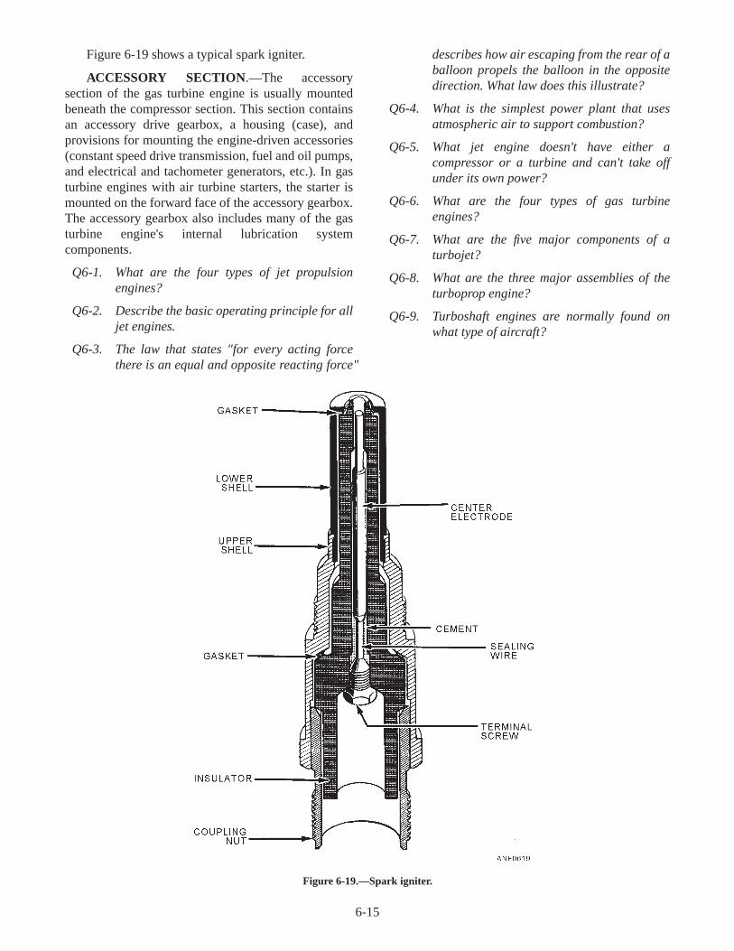
Figure 6-19 shows a typical spark igniter.
ACCESSORY SECTION.—The accessorysection of the gas turbine engine is usually mountedbeneath the compressor section. This section containsan accessory drive gearbox, a housing (case), andprovisions for mounting the engine-driven accessories(constant speed drive transmission, fuel and oil pumps,and electrical and tachometer generators, etc.). In gasturbine engines with air turbine starters, the starter ismounted on the forward face of the accessory gearbox.The accessory gearbox also includes many of the gasturbine engine's internal lubrication systemcomponents.
Q6-1. What are the four types of jet propulsionengines?
Q6-2. Describe the basic operating principle for alljet engines.
Q6-3. The law that states "for every acting forcethere is an equal and opposite reacting force"
describes how air escaping from the rear of aballoon propels the balloon in the oppositedirection. What law does this illustrate?
Q6-4. What is the simplest power plant that usesatmospheric air to support combustion?
Q6-5. What jet engine doesn't have either acompressor or a turbine and can't take offunder its own power?
Q6-6. What are the four types of gas turbineengines?
Q6-7. What are the five major components of aturbojet?
Q6-8. What are the three major assemblies of theturboprop engine?
Q6-9. Turboshaft engines are normally found onwhat type of aircraft?
6-15
Figure 6-19.—Spark igniter.

Q6-10. What is the major difference between aturboshaft and a turbofan engine?
Q6-11. What is theheart of the gas turbine fuelsystem?
Q6-12. List some of the engine-operating variablesthat are sensed by modern fuel controls.
Q6-13. What are the two main parts of a turbine thatneed lubrication?
Q6-14. In most lubricating systems, a pressure pumpor system provides oil that lubricates andcools. What system returns the oil to the tankfor reuse?
Q6-15. What is the difference between low- and high-voltage capacitor discharge ignitionsystems?
Q6-16. Where is the accessory section of the gasturbine engine usually mounted?
THE BRAYTON CYCLE
LEARNING OBJECTIVE : Recognize theBrayton cycle and its application to gas turbineand jet engines.
A cycle is a process that begins with certainconditions and ends with those same conditions. TheBrayton Cycle is illustrated in figure 6-20. Note that inthe gas turbine engine, each cycle is not only performedcontinuously, but also by a separate componentdesigned for its particular function.
Since all of the events are going on continuously,we can say that all gas turbine engines work on an opencycle. Figure 6-20 compares the cycles of operation of apiston-type (reciprocating) engine and a gas turbineengine. The piston-type engine produces power byintermittent combustion. The gas turbine engineproduces power continuously.
Q6-17. What is the Brayton cycle?
ENGINE IDENTIFICATION
LEARNING OBJECTIVE : Identify the twoengine designation systems to includesymbols, numbers, indicators, and specialdesignators.
Presently two engine designation systems identifyaircraft power plants. One system is described in Air
6-16
Figure 6-20.—A comparison of turbojet and reciprocating engine cycles.

Force-Navy Aeronautical (ANA) Bulletin No. 306M.The other system, MIL-STD-1812 designation system,includes all newly developed (Air Force, Army, andNavy) gas turbine engines.
These designation systems use standard symbols torepresent the types and models of engines now used inmilitary aircraft.
ANA BULLETIN NO. 306M DESIGNATIONSYSTEM
The following paragraph describes the ANABulletin No. 306M designation system. This system
has no provisions for Army designation. T56-A-14 isan example of this systems designation number.
Type Symbols
The first part of the designation system is a letter(or letters) that indicates each basic engine type. Table6-1 shows the letter symbols that identify engine types.
A number follows the first letter symbol. The usingarmed service assigns the number used in conjunctionwith the letter symbol as follows:
! The number 30 for the Navy. The Navy haseven numbers.
! The number 31 for the Air Force. The AirForce has odd numbers.
The designation of odd or even numbers does notrestrict the use of the engine to the sponsoring service.Aircraft engines, regardless of type designation, areused by various services, depending on theirapplicability for a particular aircraft. In some instances,engines are made interchangeable for a particularairframe.
Manufacturer's Symbol
The second part of the designation is a dash and aletter symbol that indicates the engine manufacturer.Some of the manufacturers are listed in table 6-2.
6-17
SYMBOL ENGINE TYPE
R Internal combustion, air-cooled,radial engine (reciprocating)
J Aviation gas turbine (turbojetengine)
T Aviation gas turbine (turboprop andturboshaft engines)
TF Turbofan engine
PJ Pulsejet engine
RJ Ramjet engine
Table 6-1.—Aircraft Letter Symbols and Engine Types
MANUFACTURERSYMBOL
MANUFACTURER
AD Allison Division, General Motors Corp.
BA Bell Aircraft Company
CA Continental Aviation and Engineering Corp.
CP United Aircraft of Canada Ltd.
GA AiResearch Division, Garrett Corp.
GE General Electric Company
LA Lockheed Aircraft Company
LD Lycoming Division, Avco Corp.
MD McDonald-Douglas, Aircraft Company
PW Pratt and Whitney Aircraft Division, United Aircraft Corp.
RR Rolls Royce, Ltd.
WA Curtis-Wright Corp
WE Westinghouse Electric Company
Table 6-2.—Engine Manufacturers

Special manufacturer's symbols may be assignedwhen two manufacturers are jointly producing anengine. In these instances, the manufacturer's symbol isone letter from each of the manufacturers' symbols.
Model Numbers
The third part of the designation is a dash and anumber indicating the model number.
! Navy numbers begin with 2, and they continuewith consecutive even numbers. All evenmodel numbers are assigned to enginesapproved by the Naval Air Systems Command.
! Air Force numbers begin with 1 and continuewith consecutive odd numbers.
Each engine design has only one type and modeldesignation for both the Air Force and Navy. Forexample, the Navy may wish to use an engine that hasAir Force-approved type and model numbers. TheNavy may use those numbers without change, providedthere are no engine changes. If the Air Force wants touse a Navy-approved type engine, but requires minorengine production changes, the Air Force must use theNavy type designation. The Air Force then assigns itsown model designation (which begins with the number1 and progresses with consecutive odd numbers) to themodified engine, regardless of the Navy model number.This model number is actually a modification number.It tells which service made the last production changeto the engine for a particular aircraft application.
Special Designations
The letter X or Y preceding the basic designationsignifies a special designation.
The prefix letter X is a basic engine designationsignifying the experimental and service test of aparticular engine. This prefix letter is removed aftertests prove the engine can perform as it should under alloperating conditions.
The prefix letter Y indicates a Restricted Servicedesignation. It indicates that the engine will not, or isnot expected to, perform satisfactorily under alloperating conditions. It is applied to an engine with aspecific function or that has completed a 150-hourqualification test only. Upon satisfactorily completingthe qualification testing, the Y designation is dropped.
The engine is then approved for installation in aproduction aircraft.
The following is an example of a complete ANABulletin No. 306M engine designation number:
T56-A-14
! T—Turboprop
! 56—Navy developed
! A—Allison
! 14—Navy model
The ANA Bulletin No. 306M designation system iseffective until each engine manufactured before theintroduction of MIL-STD-1812 is modified or deletedfrom service.
MIL-STD-1812 DESIGNATION SYSTEM
This engine designation system is made up ofthree-digit numerals and model numbers. It is used onall newly developed gas turbine engines. Existingengines receive a new three-digit model numberwhenever there are major changes in engineconfiguration or design. In most instances the oldtwo-digit indicator will be retained. TheMIL-STD-1812 engine designation system applies toall the armed services—Air Force, Navy, and the Army.
The complete designation system has threeparts—the type indicator, the manufacturer's indicator,and the model indicator. Special designations in thissystem are the same as those discussed under the ANABulletin No. 306M system (X or Y preceding the basicdesignation).
Type Indicator
The first part is the type indicator. It consists of thetype letter symbol and the type numeral. Letter typesymbols are shown in table 6-3:
Table 6-3.—Engine Type Indicator
INDICATOR ENGINE TYPE
J Turbojet
T Turboprop/Turboshaft
F Turbofan
6-18

The type numerals and type letter symbol areassigned consecutively by each of the services. Thenumerals begin as follows:
! 100—Air Force
! 400—Navy
! 700—Army
Model Indicator
The third part is the model indicator. It is a dash anda model number, or a dash and a model number with asuffix letter.
Each configuration of the engine has an assignedmodel number. Each of the services assigns a block ofnumbers that are used consecutively.
! 100—Air Force
! 400—Navy
! 700—Army
NOTE: If one service uses another services'designated engines, the designation remains the sameunless a model change is required. Only in this case willthe model indicator change to indicate the engine hasbeen modified.
F401-PW-400 is an example of a MIL-STD-1812engine designation.
! F Turbofan
! 401 Second Navy turbofan in designationsystem
! PW Pratt and Whitney Aircraft Division,United Aircraft Corporation
! 400 First Navy model of this particularengine
Q6-18. What are the two engine designation systemsused to identify aircraft power plants?
Q6-19. What does the letter X or Y preceding thebasic designation signify?
Q6-20. What are the three parts of theMIL-STD-1812 designation system?
Q6-21. F401-PW-400 is an example of what enginedesignation system?
POWER PLANT SAFETYPRECAUTIONS
LEARNING OBJECTIVE : Recognizepower plant safety precautions that apply to theintake ducts, exhaust area, and engine noise.
Operational readiness of a maximum number ofaircraft power plants is necessary if naval aviation is tosuccessfully perform its mission. Keeping aircraft andpower plants in top operating condition is the principalfunction of naval aviation maintenance personnel. Thismaintenance work must be performed without injury topersonnel.
Every person connected with power plantmaintenance is responsible for discovering andeliminating unsafe work practices. In the followingsection, we will discuss a few standard safetyprecautions. You must follow these precautions toprevent injury to yourself or others working on or nearaircraft jet engines.
INTAKE DUCTS
The air intake ducts of operating jet engines are anextreme hazard to personnel working near the aircraft.Ducts are also a hazard to the engine itself if the areaaround the front of the aircraft is not kept clear ofdebris. The air intake duct develops enough suction topull an individual, or hats, eye glasses, etc., into theintake. The hazard is obviously greatest duringmaximum power settings. Protective screens for theducts are part of the aircraft's ground-handlingequipment. These screens must be installed prior to allmaintenance turnups.
EXHAUST AREA
Jet engine exhausts create many hazards topersonnel. The two most serious hazards are the hightemperature and the high velocity of the exhaust gasesfrom the tailpipe. High temperatures are present severalhundred feet from the tailpipe. The closer you get to theaircraft, the higher the exhaust temperatures and thegreater the danger.
When a jet engine is starting, sometimes excessfuel will accumulate in the tailpipe. When this fuelignites, long flames shoot out of the tailpipe at veryhigh velocity. You will want to stay clear of this dangerat all times.
6-19

ENGINE NOISE
Jet engine noise can cause temporary or permanenthearing loss. Hearing loss occurs when yourunprotected ear is exposed to high sound intensities forexcessive periods of time. The higher the sound level,the less time it takes to damage your hearing. Withoutear protection, persons exposed to sound intensitiesabove 140 dB (decibels) for any length of time maysuffer serious hearing damage. You must wear properear protection at all times. You should weardoublehearing protection when working around turningaircraft.
As an Airman, you must be familiar with allaircraft general safety precautions as well as those
peculiar to your squadron. The life you save may beyour own.
Q6-22. What device must be installed before allmaintenance turnups?
Q6-23. List the two most serious hazards whenworking around engine exhausts?
Q6-24. Why should you wear ear protectors whenworking around jet engines?
SUMMARY
In this chapter, you have been introduced to jet andgas turbine engines. You have learned basic operatingprinciples and how various parts of these enginesoperate.
6-20

ASSIGNMENT 6
Textbook Assignment: "Aircraft Power Plants," chapter 6, pages 6-1 through 6-20.
6-1. In 250 B.C., the first reaction engine was builtby what group of people?
1. Romans2. Egyptians3. Greeks4. Babylonians
6-2. Naval aircraft jet propulsion engines may beidentified by what total number of categories?
1. One2. Two3. Three4. Four
6-3. The gas turbine engine powers almost all Navyaircraft.
1. True2. False
6-4. Rocket engines carry their own oxidizer forcombustion for what primary reason?
1. For travel above the atmosphere2. For travel within the atmosphere3. To take the place of hydrogen4. To take the place of carbon
6-5. Jet propulsion engine operations can be ex-plained by which of the following laws ofmotion?
1. Newton's first2. Newton's second3. Newton's third4. Newton's fourth
6-6. When the stem of an inflated balloon is re-leased, what action causes the balloon to moveforward?
1. The force of the escaping air2. The low-pressure area against the front of
the balloon3. The pressure from inside the balloon
pushing against the outside air4. The pressure of the air on the inside of the
balloon directly opposite the open stem
6-7. A basic gas turbine engine consists of whattotal number of major sections?
1. Six2. Five3. Three4. Four
6-8. Most of the air taken into the combustionchamber of a jet engine is used for whatpurpose?
1. Compression2. Propulsion3. Combustion4. Cooling
6-9. A compressor stage consists of what row(s) ofblades or vanes?
1. Rotating blades only2. Stator vanes only3. Rotating blades and stator vanes4. Three or more rows of rotating blades and
stator vanes
6-10. In a compressor, the air pressure increases eachtime it passes through a set of rotors and statorsfor which of the following reasons?
1. The areas of the rotors and stators getslarger
2. The areas of the rotors and stators getssmaller
3. The spool area of the stators increases4. The spool area of the rotors increases
6-11. Since the initial appearance of the split-spoolcompressor engine, the potential thrust oftoday's engines has been boosted considerably.These compressors are driven individually bywhat means?
1. The turbine assembly2. Separate wheels of the turbine assembly3. The rotor assembly4. The stator assembly
6-21

6-12. Compressor stalls may be eliminated by usingwhich of the following systems?
1. Rotor vane and stator vane system2. Inlet guide vane and stator vane system3. Front and rear compressor system4. Compressor bleed-air system and variable
vane system
6-13. Which of the following is NOT a basicrequirement for a satisfactory and efficientcombustion chamber system?
1. Light weight2. A minimum pressure drop3. A high rate of burning4. Can-annular design
6-14. Fuel is introduced into the combustionchamber at what location?
1. Back of the combustion chamber2. Top of the combustion chamber3. Front of the combustion chamber4. Bottom of the combustion chamber
6-15. A gas turbine engine normally has provisionsfor what total number of igniter plugs in thecombustion chamber?
1. One2. Two3. Three4. Four
6-16. The flame from the chambers containing theigniter plugs is spread to the remainingchambers through what design feature?
1. Guide vanes2. Drilled holes3. Flame tubes/cross ignition tubes4. Louvers
6-17. What percent of the air in the combustionchamber actually takes part in the combustionprocess?
1. 25%2. 35%3. 45%4. 55%
6-18. Secondary air is used in the combustionchamber for what purpose?
1. To dilute and cool the hot gases2. To help the combustion process3. To drive the compressor4. To drive the turbine
6-19. What function does the turbine assemblyserve?
1. It develops exhaust gas power2. It reduces the speed of the compressor3. It increases the turbine gas temperatures4. It drives the compressor
6-20. The flowing gases from the combustionchamber of a turbojet engine act directlyagainst what engine component?
1. Impeller2. Compressor3. Turbine disk blades4. Auxiliary equipment
6-21. Turbine blades are normally made from whatmaterial alloy?
1. Copper2. Aluminum3. Magnesium4. Steel
6-22. What is the function of the inner cone in theexhaust section?
1. To eliminate exhaust gas turbulence2. To direct air to the outer exhaust cone3. To give support to the exit guide vanes4. To cool the turbine wheel
6-23. The inner cone is attached to the outer cone bywhat means?
1. Copper alloy tubes2. Streamlined vanes called brace assemblies3. Stainless steel sheets4. Tapered cylinder-shaped brackets
6-24. The exhaust cone is made from what material?
1. Aluminum alloy2. Stainless steel sheets3. High-temperature alloy4. Low-temperature alloy
6-25. What material is used to insulate the cone?
1. High-temperature alloy2. Copper sheets3. Aluminum alloy sheets4. Aluminum foil
6-26. The turboprop engine is capable of developingwhat maximum horsepower per pound ofweight?
1. 1/2 hp2. 1 1/2 hp3. 2 hp4. 2 1/2 hp
6-22
6-27. A turboprop engine has what total number ofmajor assemblies?
1. One2. Two3. Three4. Four
6-28. What component of the power section of aturboprop engine provides the power thatdrives the propeller?
1. Turbine2. Combustion chamber3. Compressor4. Exhaust
6-29. Torsional deflection in a turboprop engine is anindication of what variable?
1. Temperature2. Horsepower3. Pressure4. Rpm
6-30. What is the function of the reduction gearassembly?
1. To change the propeller blade angle to avariable rpm
2. To provide a constant rpm unit forpropeller operation
3. To reduce the engine rpm to within therange of efficient propeller rpm
4. To provide higher propeller rpm than theengine provides
6-31. What is the basic function of the propellerassembly?
1. To efficiently develop thrust2. To drive the reduction gearbox assembly3. To drive the compressor section4. To efficiently develop rpm
6-32. Turboshaft engines are currently being used onwhich of the following types of aircraft?
1. Fighters2. Attack3. Transport4. Helicopters
6-33. Which of the following types of gas turbineengines operates on the free turbine principle?
1. Turboprop2. Turboshaft3. Turbofan4. Turbojet
6-34. During all operations of the turboshaft engine,automatic protection is provided for which ofthe following malfunctions?
1. Turbine overspeed, compressor stall,combustion flame-out, and turbineovertemperature
2. Compressor overspeed, turbine stall,turbine overtemperature, and combustionflame-out
3. Combustion flame-out, turbine undertemperature, turbine overspeed, andcompressor stall
4. Turbine underspeed, compressor stall,combustion flame-out, and turbineovertemperature
6-35. Operation of the turbofan engine is similar towhich of the following gas turbine engines?
1. Turboshaft2. Turbojet3. Turboprop4. Turbopulse
6-36. The turbofan engine has a low rate of fuelconsumption.
1. True2. False
6-37. A turbofan powered aircraft that isapproximately the same size as a turbojetaircraft is capable of accomplishing which ofthe following tasks?
1. Handling higher gross weight at takeoff2. Producing more thrust during climb3. Using shorter takeoff distance4. Each of the above
6-38. What factor causes the low noise level of theturbofan engine?
1. The enclosed fan, which is driven at theengine's speed
2. The high velocity of compressed air thatpasses through the burner and turbinesections
3. The increased thrust from the use of theafterburner
4. The low gas velocity coming out of thetailpipe
6-39. What are the two basic groups of modern fuelcontrol systems?
1. Pneumatic and pressure2. Hydromechanical and electronic3. Automatic and manual4. Pressure and mechanical
6-23

6-40. What is considered to be the "heart" of a gasturbine engine fuel system?
1. Fuel control2. Fuel cell pumps3. Fuel cross-feed valves4. Fuel shutoff valve
6-41. Which of the following inputs does the fuelcontrol system combine to operate a gasturbine engine?
1. Fuel flow, compressor pressure, turbinespeed, and temperature
2. Combustion, ignition, altitude, fuel flow,and acceleration
3. Engine speed, altitude, exhausttemperature, and throttle position
4. Throttle position, compressor dischargepressure, engine speed, and compressorinlet temperature
6-42. What lubrication system returns engine oilback to the oil tank for reuse?
1. Pressure pump system2. Wet sump system3. Scavenge system4. Pressurized sump system
6-43. The purpose of a pressurized oil tank in thelubricating system of a gas turbine engine is toprevent pump cavitation under what condition?
1. High altitude2. Engine start3. Low altitude4. Engine stop
6-44. The lubricating system used on a gas turbineengine is, with few exceptions, always the drysump design.
1. True2. False
6-45. What type of oil is used in all gas turbineengine lubrication systems?
1. Synthetic oil2. Petroleum-based oil3. Animal fat-based oil4. Mineral-based oil
6-46. What type of ignition system has beenuniversally accepted for use in a gas turbineengine?
1. Low spark, capacitor2. High capacitor, low spark3. High energy, capacitor4. Low capacitor, low energy
6-47. To avoid a lethal electrical shock from theignition system, which of the followingcomponents must be grounded beforemaintenance work can be started?
1. Resistors2. Igniter plugs3. Spark plugs4. Capacitors
6-48. The accessory section is usually mounted towhat section on a gas turbine engine?
1. Turbine section2. Combustion section3. Compressor section4. Exhaust section
6-49. The term used to describe a process that beginswith certain conditions and ends with thosesame conditions is known as "Brayton Cycle."
1. True2. False
6-50. The MIL-STD-1812 designation system has noprovision for what branch of the armed forces?
1. Navy2. Army3. Air Force4. Coast Guard
IN ANSWERING QUESTIONS 6-51 THROUGH6-53, REFER TO TABLE 6-1.
6-51. What aircraft letter symbol identifies a turbojetengine?
1. RJ2. R3. J4. T
6-52. What aircraft letter symbol identifies aturboshaft engine?
1. R2. J3. T4. TF
6-53. What aircraft letter symbol identifies aturbofan engine?
1. R2. J3. T4. TF
6-24

6-54. Following the first letter symbol identifying theengine type, a number appears to identify theservice that uses the engine(s). Which of thefollowing numbers represents an Air Forceengine?
1. 202. 303. 314. 40
IN ANSWERING QUESTIONS 6-55 THROUGH6-58, REFER TO TABLE 6-2 IN THE TEXT.
6-55. The manufacturer's symbol BA identifieswhich aircraft engine manufacturer?
1. Allison Division, General MotorsCorporation
2. General Electric Company3. Bell Aircraft Company4. McDonald–Douglas Aircraft Company
6-56. What engine manufacturer's symbol identifiesthe Lockheed Aircraft Company?
1. LA2. LD3. AD4. GA
6-57. The manufacturer's symbol PW identifieswhich aircraft engine manufacturer?
1. Rolls Royce, Ltd.2. Westinghouse Electric Company3. AiResearch Division, Garrett Corporation4. Pratt and Whitney Aircraft Division
6-58. What engine manufacturer's symbol identifiesthe Curtis-Wright Corporation?
1. WE2. WA3. PW4. MD
6-59. When two manufacturers' are jointly producingan engine, the symbol is one letter from eachmanufacturer's symbols.
1. True2. False
6-60. The third part or section of the enginedesignation consists of a dash and a numberindicating the model number. The Navy modelnumber begins with 2 and continues withconsecutive even numbers.
1. True2. False
6-61. Under special engine designations, what prefixletter is assigned to experimental and servicetest engines?
1. W2. X3. Y4. Z
6-62. Under special engine designations, what prefixletter is assigned to restricted service engines?
1. W2. X3. Y4. Z
6-63. Normally the restricted service designation foran engine is dropped after completion of whattotal number of qualifying test hours?
1. 50 hr2. 100 hr3. 150 hr4. 200 hr
6-64. The MIL-STD-1812 engine designationsystem is made up of what total number ofparts or sections?
1. One2. Two3. Three4. Four
6-65. The Air Force, Navy, and Army are assigned ablock of engine configuration model numbersthat are used consecutively.
1. True2. False
6-66. What series or block of engine configurationmodel numbers are assigned to the Navy?
1. 1002. 4003. 700
6-67. Which of the following characters identifiesthe type of engine in the designation numberF401–PW–400?
1. F2. 4013. PW4. 400
6-25

6-68. Which of the following characters identifiesthe engine manufacturer in the designationnumber F401–PW–400?
1. F2. 4013. PW4. 400
6-69. Which of the following personnel is/areresponsible for trying to discover and eliminateunsafe work practices?
1. Commanding officer2. Maintenance officer3. Work center supervisor4. All hands
6-70. The greatest hazard of working near the aircraftintake ducts occurs during which of thefollowing operations?
1. Engine start2. Engine stop3. Maximum power4. Minimum power
6-71. Serious hearing damage may occur tounprotected ears if the dB (decibel) level isgreater than what maximum level?
1. 140 dB2. 120 dB3. 110 dB4. 100 dB
6-26