Embed Size (px)
Citation preview

Control of Bandstop Response of Cascaded Microstrip Low-pass-Bandstop Filters
Using Arrowhead Slots in Backside Metallic Ground Plane
Dr. Galal Nadim
Brief • A new equivalent circuit and modeling method for a uniform
arrowhead-defected-ground-structure slot are proposed for the design of a DGS-cascade lowpass or bandstop filter
• The effect of the geometry of a defected ground structure (DGS) on the performance of the cascaded-LPF or BSF and the effect of the cascaded Method are examined.
• The proposed LPF or BSF based on π -arrowhead DGS slot is 70% shorter than a conventional LPF
• It was found that only three cells of the proposed structure are necessary for a 15-dB stopband at 6 GHz
• The validity of the proposed equivalent circuit model is established by comparing their response to the full-wave EM simulation of several structures
• Measured results show that the new designs exhibit better performance by suppressing ripples and enlarging stopband bandwidth

Defected Ground Structures (DGS)• Defected ground structures (DGS) which are realized by
etching defects in the backside metallic ground plane under a microstrip line
• A basic and widely used DGS cell is composed of two wide defected areas and a narrow connecting slot
• A DGS-slot combination has a simple structure and can be modeled as a parallel LC resonator
• Such a structure blocks the signal around its resonant frequency and may be used to introduce a notch or enhance and widen the stopband of lowpass or clean up filters
• The characteristics of such filters are sharp transitions between the passband and the stopband, low insertion loss in the passband and strong attenuation in a wide stopband.
•
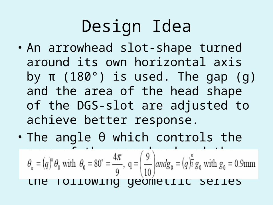
Design Idea• An arrowhead slot-shape turned around its
own horizontal axis by π (180°) is used. The gap (g) and the area of the head shape of the DGS-slot are adjusted to achieve better response.
• The angle θ which controls the area of the arrowhead and the gap g are varied according to the following geometric series

(a) DGS element,(b) Equivalent circuit of
DGS element,

Simulated S parameters for different values of g
• The comparison, between the fabricated filter, the simulated and the calculated measurements, shows an agreement up to 90%. Measurements, also, show that the filter exhibits better performances by suppressing ripples, widening stopband bandwidth and introducing high sharpness for the transition from passband to stopband.

MODELING AND EXTRACTION METHOD
• The parameters of a DGS-slot combination can be extracted from the following procedure.
• Therefore, the L-element value, which is scaled to Z0 and fc, can be determined from

Arrowhead-slot modeling. (a)DGS element (bottom). (b) Extracted equivalent circuit.(c) S11and S12 for EM- and circuit simulation

DESIGN OF THE PROPOSED PERIODIC DGS
Schematic views of (a) structure 1, (b) structure 2 , and (c) S-parameter of (a)structure 1 and (b) structure 2

Schematic views of (c) structure 2, (d) structure 3 , and (e) S-parameter of bothstructures

• Based on structure 4, another improved cascaded open-stub filter have been designed as shown
Schematic of Layout (b) of the cascaded LPF with 3-sectionDGS and(a) equivalent circuit

Fabricated DGS low-pass filter with cascaded filter using slots and open stubs .(a) Bottom view. (b) Top view . Measured & Simulated (c)S12 & (d)S11

Conclusion• An improved triangle-slot DGS which has an inverse
arrowhead and non-uniform gap as defect slot in the backside metallic ground plane is presented.
• Lowpass filters with wide stopband can be designed by cascading a suitable number of DGS elements in which the angle of the inverse arrowhead defect and the gap g are varied in the outward direction following a geometric series
• A fabricated LPF shows a stopband from 5.7 to 11.7GHz, 0.3 dB insertion loss without ripples in the passband and a sharp transition between the passband the stopband
• The compactness and simplicity of the structure make the proposed filters a strong candidate for applications in various integrated microwave circuits.