Embed Size (px)
Citation preview
Connection Couplings HyCon, HyLoc and HyGrip

Voith Turbo Safeset
We are the experts in torque-limiting and connection couplings at Voith Turbo.
Voith Turbo, the specialist for hydrodynamic drive, coupling and braking systems for road,
rail and industrial applications, as well as for ship propulsion systems, is a Group Division
of Voith AG.
Voith is one of the largest family-owned companies in Europe with a workforce of around
39,000, EUR 5.1 billion in sales in the 2008/2009 fiscal year and 280 sites worldwide. The
company is active in the energy, oil and gas, paper and raw materials as well as transpor-
tation and automotive markets around the world.

Voith Turbo I Connection Couplings HyCon, HyLoc and HyGrip I G 1578 en 3
Principle HyCon, HyLoc and HyGrip
Voith connection couplings provide a backlash-free, frictional,
quick setting/releasing shaft-hub connections. The setting or
releasing occurs hydraulically. Depending on the application,
various operating principles are available, all of which offer the
advantage of a backlash-free pressure connection.
HyCon HyLoc HyGrip
n Mechanical shaft-shaft/shaft-flange connection
n Hydraulically set and releasedn Oil pressure is not required for
transmitting torque
n Mechanical shaft-hub connectionn Hydraulically set and releasedn Oil pressure is not required for
transmitting torque
n Hydraulic hollow sleeve-shaft-hub connection
n Pumped up hydraulicallyn Oil pressure is required for transmitting
torque
By hydraulically pushing a tapered outer sleeve upon a tapered inner sleeve, a radial force is created. Subsequently a frictional connection is created between shaft, coupling and shaft/flange.
By hydraulically pushing a tapered sleeve inside a coupling unit, a radial force is created. Subsequently a frictional connection is created between shaft, coupling and hub.
By hydraulically expanding a coupling unit, a radial force is created. Subsequently a frictional connection is created between shaft, coupling and hub.
During setting and releasing, the shaft hub remains static, only the tapered outer sleeve is moved.
During setting and releasing, the shaft hub remains static, only the tapered con- ical sleeve inside the coupling moves.
During setting and releasing, the shaft hub remains static.

Voith Turbo I Connection Couplings HyCon, HyLoc and HyGrip I G 1578 en4
Connecting applications HyCon, HyLoc and HyGrip
Marine: propulsion shafts and drive line components Navy: propulsion shafts and drive line components
Metal processing: roll connections, slitting equipment, grinding shafts and drive train components
Power generation: driveline components

Voith Turbo I Connection Couplings HyCon, HyLoc and HyGrip I G 1578 en 5
Mining: driveline components
Voith Turbo I Connection Couplings HyCon, HyLoc and HyGrip I G 1578 en6
HyCon
A breakthrough in connection technology
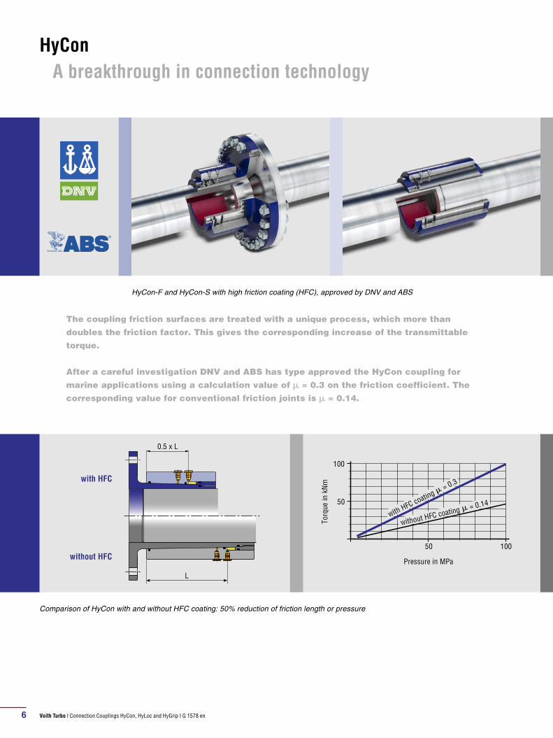
The coupling friction surfaces are trea ted with a unique process, which more than
doubles the friction factor. This gives the corresponding increase of the transmittable
torque.
After a careful investigation DNV and ABS has type approved the HyCon coupling for
marine applications using a calculation value of m = 0.3 on the friction coef fi cient. The
corresponding value for conventional friction joints is m = 0.14.
Comparison of HyCon with and without HFC coating: 50% reduction of friction length or pressure
HyCon-F and HyCon-S with high friction coating (HFC), approved by DNV and ABS
L
0.5 x L
with HFC
without HFC
100
50
50
100
with HFC coating m = 0.3
without HFC coating m = 0.14
Torq
ue in
kN
m
Pressure in MPa

Voith Turbo I Connection Couplings HyCon, HyLoc and HyGrip I G 1578 en 7
1. Shaft is removed or pushed into correct axial position.
2. Connect both hydraulic hoses to hydraulic fittings “P1” and “P2”. Activate the pump. With increasing pressure, the hub moves in the direction of the arrow. Once the set pressure is reached (approximately 1000 bar) open the valve “R” and the relief valve at the pump. It is now safe to remove the hydraulic hoses.
3. HyCon is now set without any internal oil pressure.
4. Connect both hydraulic hoses again to “P1” and “P2”. Open valve “A” and close valve “R”. Activate the pump until a pressure of approximately 400 bar is achieved, then close valve “A”. Carry on pumping until the hub re-leases which results in a slight pressure increase at the gauge “M”. Slowly open valve “R”. The hub returns back to its original position. It is now safe to remove the hy-draulic hoses.
Setting and releasing
3. Ready for operation
1. Depressurized
4. Release
Pump
P1 P2
A R
M
2. Pressurising
Pump
P1 P2
A R
M

Voith Turbo I Connection Couplings HyCon, HyLoc and HyGrip I G 1578 en8
HyCon F/FX and S/SX series
Typical applications
n Marine: Connect shaft sections in conventional
propulsion drive linesn Marine: Connect drive lines to waterjets,
thrusters etc.n Industrial: Connect drive shafts in heavy
industry
Design and function
The HyCon connection coupling consists mainly
of a tapered sleeve and a tapered hub. By means
of a sealed piston sleeve, a piston space is cre-
ated which exerts hydraulic axial forces on the
hub when pressure is applied. Consequently, the
hub is pushed up the taper of the sleeve, which
results in a radial compression. In order to carry
out this process at minimum pressure and with-
out wear, the surface of the taper is lubri cated
with pressurised oil. The surface of the taper is
sealed on both sides, thus no leakage can occur.
In order to release the connection, oil is pumped
in between the tapered surfaces until they are
separated and the sleeve is moved down by the
axial forces generated.
HyCon type F/FX

Voith Turbo I Connection Couplings HyCon, HyLoc and HyGrip I G 1578 en 9
Feature Benefits
High torque capacity due to high friction coating (HFC) n Ideally suited for thin hollowed shaftsn No internal reinforcement sleeves necessary
Low weight n Reduced system weightn Increased effective load especially in ships and boatsn Excellent resistance against shock loads in the driveline
Low mass moment of inertia n Reduced system vibrations
F/FX: Flange connection on inner sleeve n Simple positioning of the couplingn Connection bolts can be tightened before pressurizing of the coupling
S/SX: Shaft to shaft connection n Low hydrodynamic resistance when located outboard in ships and boats
Hot plate mill, HyCon SX630 installed between motor and interme-diate shaft on a twin drive arrangement (design torque 4200 kNm)
Cold rolling mill, HyCon F315 installed between roll and universal joint
Industrial application designs
ø 6
30
ø 3
15

Voith Turbo I Connection Couplings HyCon, HyLoc and HyGrip I G 1578 en10
1 Shaft2 Hub3 Hollow sleeve4 Conical ring piston5 Sealing valve/pump hose con-
nection
HyLoc type HC-B
5
1
4
3
2
Design and function
The HyLoc connection coupling consists of a hol-
low sleeve, where the internal chamber is a con-
ical ring piston that is moved hydraulically. The
ensuing radial expansion produces a backlash-
free connection between a shaft and a hub.
The pres sure required for assembly is normally
1000 bar. A maximum of 1200 bar is usually re-
quired for disassembly. After assembly, the oil is
drained, so that there is no residual oil pressure
in the coupling during operation. The same ap-
plies for disassembly. The ring piston is provided
with specially arranged lubrication grooves,
hence a lubricating film is created when the ring
piston moves between the working surfaces.
HyLoc
Typical applications
n Industrial: Fixing of straightening and cutting
rolls in the steel industryn Industrial: Fixing of different hubs and runners
as flywheels, turbines etc.n Industrial: Knife/blade holders for rotating
sitters to cut sheet metal or papern Industrial: Blade holders for cutting thick sheet
metals, e.g. in wide strip hot rolling mills
HyLoc disc knife holder type HC-B

Voith Turbo I Connection Couplings HyCon, HyLoc and HyGrip I G 1578 en 11
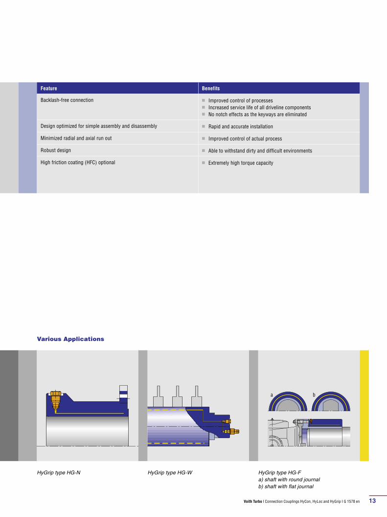
Feature Benefits
Backlash-free connection n Improved control of processesn Increased service life of all driveline componentsn No notch effects as the keyways are eliminated
Design optimized for simple assembly and disassembly n Rapid and accurate installation
Minimized radial and axial run out n Improved control of actual process
Design optimized for withstanding high radial forces n Ideally suited for roll connections
Robust design n Able to withstand dirty and difficult environments
High friction coating (HFC) optional n Extremely high torque capacity
ON OFF
Connection of the hydraulic pumpON: setting/pressurizingOFF: releasing/depresurizing

Voith Turbo I Connection Couplings HyCon, HyLoc and HyGrip I G 1578 en12
HyGrip
HyGrip type HG-B
5
1
4
3
2
1 Shaft2 Hub3 Hollow sleeve4 Pump hose connection5 Sealing valve
Design and function
The HyGrip connection coupling consists of a
twin-walled pressure sleeve. It is pressurized
with oil to 1200 bar and sealed with a brass
valve. This results in a completely backlash-free
frictional connection.
HyGrip connection couplings can be specifically
designed to meet the exact requirements of the
application.
The torque transmission capacity and the axial
forces are proportional to the oil pressure. The
connection can be set and released very quickly
if a suitable hydraulic pump is used.
Typical applications
n Industrial: Fixing of straightening rolls and
cutting rolls where the radial forces are lown Industrial: Fixing of flexible drive shafts and
couplings for easy assembly and disassemblyn Industrial: Knife/blade holders for rotating
slitters to cut sheet metal or paper
HyGrip disc knife holder type HG-B
Voith Turbo I Connection Couplings HyCon, HyLoc and HyGrip I G 1578 en 13
Feature Benefits
Backlash-free connection n Improved control of processesn Increased service life of all driveline componentsn No notch effects as the keyways are eliminated
Design optimized for simple assembly and disassembly n Rapid and accurate installation
Minimized radial and axial run out n Improved control of actual process
Robust design n Able to withstand dirty and difficult environments
High friction coating (HFC) optional n Extremely high torque capacity
HyGrip type HG-N HyGrip type HG-W HyGrip type HG-Fa) shaft with round journalb) shaft with flat journal
a b
Various Applications

Voith Turbo I Connection Couplings HyCon, HyLoc and HyGrip I G 1578 en14
HyCon F HyCon FX
SizeT
[kNm]D1
[mm]D2
[mm]Df
[mm]DD1
[mm]L1
[mm]L2
[mm]m
[kg]J
[kgm2]Size
T [kNm]
D1 [mm]
D2 [mm]
Df [mm]
DD1 [mm]
L1 [mm]
L2 [mm]
m [kg]
J [kgm2]
80 14.7 80 130 185 0.06 113 87 8 0.027 80 26.6 80 145 235 0.06 182 139 19 0.092
90 21.4 90 147 210 0.06 125 95 11 0.050 90 39.1 90 164 285 0.06 202 153 29 0.201
100 29.1 100 158 235 0.06 135 103 14 0.077 100 53 100 177 305 0.06 222 168 37 0.293
110 38.4 110 174 260 0.08 149 114 19 0.126 110 69.7 110 194 325 0.08 243 185 47 0.432
120 50.5 120 191 285 0.08 166 125 25 0.205 120 92.3 120 214 345 0.08 269 202 62 0.657
130 65.3 130 207 305 0.08 176 132 31 0.294 130 120 130 233 390 0.08 289 216 82 1.093
140 82.6 140 223 325 0.08 194 147 40 0.425 140 153 140 252 415 0.08 317 237 104 1.573
150 102 150 240 345 0.08 205 154 49 0.597 150 191 150 270 455 0.08 336 250 130 2.344
160 126 160 256 365 0.08 216 161 58 0.801 160 235 160 289 475 0.08 358 265 156 3.101
170 151 170 272 390 0.085 226 168 69 1.084 170 282 170 307 495 0.085 377 278 183 4.008
180 179 180 288 415 0.09 236 175 81 1.441 180 335 180 324 525 0.09 395 291 214 5.269
190 211 190 303 435 0.095 247 183 93 1.836 190 393 190 343 555 0.095 416 305 253 6.973
200 246 200 320 455 0.1 257 190 108 2.342 200 458 200 362 575 0.1 435 318 291 8.723
220 327 220 351 495 0.11 278 204 139 3.612 220 610 220 400 620 0.11 473 344 380 13.439
240 424 240 383 525 0.12 302 220 176 5.306 240 793 240 436 675 0.12 512 372 489 20.531
260 540 260 416 575 0.13 322 234 224 8.028 260 1000 260 470 730 0.13 549 398 610 30.024
280 674 280 448 605 0.14 344 249 272 11.056 280 1260 280 506 810 0.14 588 426 777 46.345
300 830 300 480 635 0.15 365 264 327 14.942 300 1540 300 542 840 0.15 626 452 924 60.444
320 1000 320 511 695 0.16 385 277 398 21.247 320 1880 320 578 890 0.16 663 478 1108 81.825
340 1200 340 544 730 0.17 407 291 473 28.282 340 2250 340 614 955 0.17 701 504 1333 112.763
360 1430 360 576 760 0.18 427 305 550 36.259 360 2680 360 650 1000 0.18 738 530 1560 145.829
380 1680 380 607 820 0.19 447 319 651 48.860 380 3150 380 685 1040 0.19 775 556 1799 183.807
400 1960 400 639 855 0.2 469 332 751 61.957 400 3670 400 721 1115 0.2 812 581 2121 246.385
T: torque m: mass J: mass moment of inertia DD1: Assembly clearance shaft-bore
Technical Data HyCon F and FX series
L2
L1
D1
D2
ø D
f
tolerance h7 or to customer demand

Voith Turbo I Connection Couplings HyCon, HyLoc and HyGrip I G 1578 en 15
HyCon S HyCon SX
SizeT
[kNm]D1
[mm]D2
[mm]DD1
[mm]L1
[mm]L2
[mm]m
[kg]J
[kgm2]Size
T [kNm]
D1 [mm]
D2 [mm]
DD1 [mm]
L1 [mm]
L2 [mm]
m [kg]
J [kgm2]
80 15.6 80 125 0.06 142 51 8 0.022 80 28.7 80 136 0.06 253 102 19 0.059
90 22.6 90 140 0.06 157 58 11 0.039 90 41.8 90 154 0.06 282 116 27 0.108
100 31.3 100 152 0.06 173 64 14 0.058 100 58.7 100 165 0.06 311 128 33 0.154
110 40.6 110 166 0.08 189 70 18 0.089 110 75.5 110 180 0.08 342 140 43 0.238
120 53.5 120 181 0.08 206 76 23 0.138 120 99.5 120 197 0.08 371 152 56 0.371
130 68.9 130 196 0.08 222 83 29 0.204 130 129 130 214 0.08 400 165 71 0.559
140 86.5 140 212 0.08 244 89 38 0.308 140 163 140 231 0.08 435 177 91 0.826
150 107 150 227 0.08 257 95 46 0.426 150 203 150 247 0.08 461 189 110 1.143
160 131 160 240 0.08 272 101 54 0.558 160 248 160 264 0.08 489 201 133 1.584
170 157 170 256 0.085 285 107 64 0.760 170 298 170 280 0.085 515 213 157 2.108
180 187 180 272 0.09 298 113 76 1.016 180 354 180 296 0.09 541 225 184 2.763
190 220 190 286 0.095 314 119 89 1.304 190 415 190 314 0.095 570 238 220 3.698
200 256 200 300 0.1 327 125 101 1.638 200 485 200 330 0.1 596 250 253 4.712
220 341 220 331 0.11 354 137 134 2.636 220 645 220 363 0.11 649 274 334 7.513
240 443 240 360 0.12 382 149 170 3.968 240 838 240 394 0.12 703 298 423 11.259
260 563 260 391 0.13 409 162 215 5.927 260 1060 260 427 0.13 757 323 536 16.728
280 704 280 420 0.14 437 174 264 8.410 280 1330 280 460 0.14 811 348 666 24.143
300 865 300 450 0.15 465 186 323 11.792 300 1630 300 492 0.15 864 372 810 33.623
320 1050 320 479 0.16 491 198 385 15.952 320 1980 320 525 0.16 916 396 978 46.227
340 1260 340 510 0.17 519 211 462 21.714 340 2380 340 558 0.17 971 421 1172 62.548
360 1490 360 540 0.18 545 223 544 28.660 360 2830 360 590 0.18 1022 445 1377 82.211
380 1760 380 570 0.19 571 235 635 37.276 380 3320 380 625 0.19 1074 469 1630 109.039
400 2050 400 600 0.2 597 247 736 47.850 400 3870 400 655 0.2 1126 493 1868 137.510
T: torque m: mass J: mass moment of inertia DD1: Assembly clearance shaft-bore
HyCon S and SX series
L2
L1
D1
D2
Voith Turbo I Connection Couplings HyCon, HyLoc and HyGrip I G 1578 en16
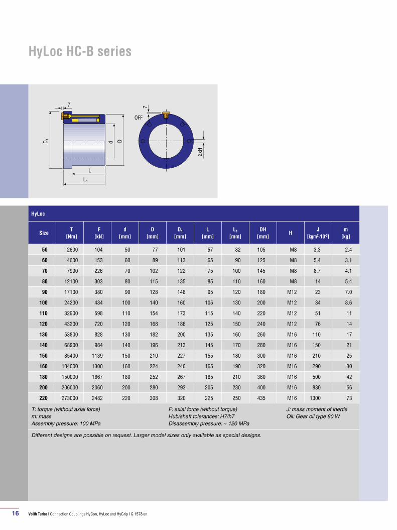
HyLoc
SizeT
[Nm]F
[kN]d
[mm]D
[mm]D1
[mm]L
[mm]L1
[mm]DH
[mm]H
J [kgm2·10-3]
m [kg]
50 2600 104 50 77 101 57 82 105 M8 3.3 2.4
60 4600 153 60 89 113 65 90 125 M8 5.4 3.1
70 7900 226 70 102 122 75 100 145 M8 8.7 4.1
80 12100 303 80 115 135 85 110 160 M8 14 5.4
90 17100 380 90 128 148 95 120 180 M12 23 7.0
100 24200 484 100 140 160 105 130 200 M12 34 8.6
110 32900 598 110 154 173 115 140 220 M12 51 11
120 43200 720 120 168 186 125 150 240 M12 76 14
130 53800 828 130 182 200 135 160 260 M16 110 17
140 68900 984 140 196 213 145 170 280 M16 150 21
150 85400 1139 150 210 227 155 180 300 M16 210 25
160 104000 1300 160 224 240 165 190 320 M16 290 30
180 150000 1667 180 252 267 185 210 360 M16 500 42
200 206000 2060 200 280 293 205 230 400 M16 830 56
220 273000 2482 220 308 320 225 250 435 M16 1300 73
T: torque (without axial force) m: mass Assembly pressure: 100 MPa
F: axial force (without torque) Hub/shaft tolerances: H7/h7 Disassembly pressure: ~ 120 MPa
J: mass moment of inertia Oil: Gear oil type 80 W
Different designs are possible on request. Larger model sizes only available as special designs.
HyLoc HC-B series
OFF
2xH
D1 Dd
7 7
L
L1
Voith Turbo I Connection Couplings HyCon, HyLoc and HyGrip I G 1578 en 17
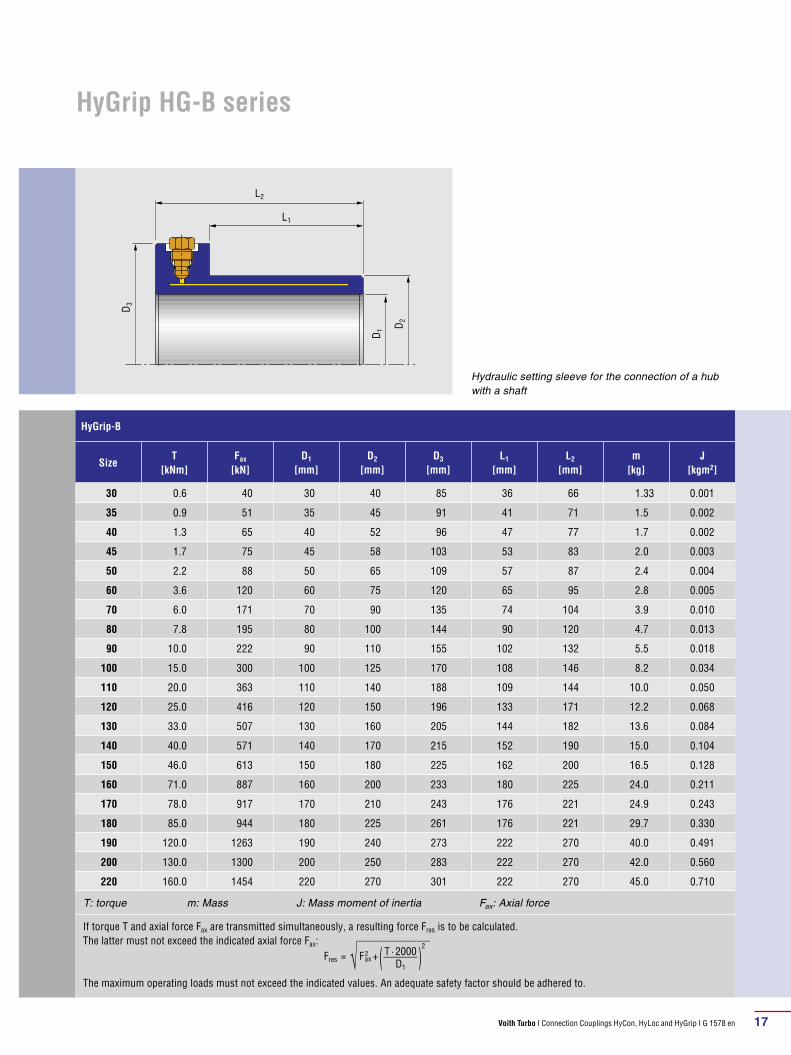
HyGrip-B
SizeT
[kNm]Fax
[kN]D1
[mm]D2
[mm]D3
[mm]L1
[mm]L2
[mm]m
[kg]J
[kgm2]
30 0.6 40 30 40 85 36 66 1.33 0.001
35 0.9 51 35 45 91 41 71 1.5 0.002
40 1.3 65 40 52 96 47 77 1.7 0.002
45 1.7 75 45 58 103 53 83 2.0 0.003
50 2.2 88 50 65 109 57 87 2.4 0.004
60 3.6 120 60 75 120 65 95 2.8 0.005
70 6.0 171 70 90 135 74 104 3.9 0.010
80 7.8 195 80 100 144 90 120 4.7 0.013
90 10.0 222 90 110 155 102 132 5.5 0.018
100 15.0 300 100 125 170 108 146 8.2 0.034
110 20.0 363 110 140 188 109 144 10.0 0.050
120 25.0 416 120 150 196 133 171 12.2 0.068
130 33.0 507 130 160 205 144 182 13.6 0.084
140 40.0 571 140 170 215 152 190 15.0 0.104
150 46.0 613 150 180 225 162 200 16.5 0.128
160 71.0 887 160 200 233 180 225 24.0 0.211
170 78.0 917 170 210 243 176 221 24.9 0.243
180 85.0 944 180 225 261 176 221 29.7 0.330
190 120.0 1263 190 240 273 222 270 40.0 0.491
200 130.0 1300 200 250 283 222 270 42.0 0.560
220 160.0 1454 220 270 301 222 270 45.0 0.710
T: torque m: Mass J: Mass moment of inertia Fax: Axial force
If torque T and axial force Fax are transmitted simul taneously, a resulting force Fres is to be calculated. The latter must not exceed the indicated axial force Fax:
The maximum operating loads must not exceed the indicated values. An adequate safety factor should be adhered to.
Fres = √___________
F 2 a x + ( T · 2000 _____ D1
) 2
HyGrip HG-B series
Hydraulic setting sleeve for the connection of a hub with a shaft
D1
L2
L1
D3
D2
Voith Turbo I Connection Couplings HyCon, HyLoc and HyGrip I G 1578 en18
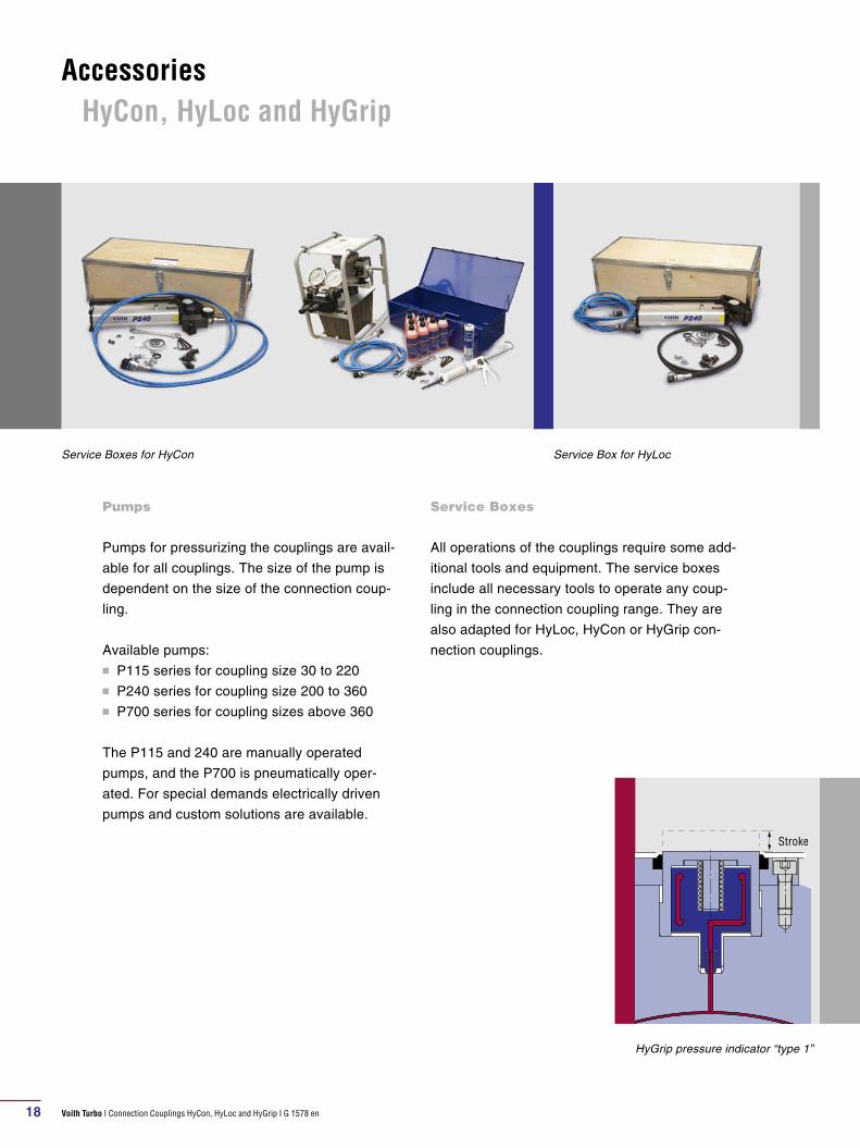
Pumps
Pumps for pressurizing the couplings are avail-
able for all couplings. The size of the pump is
dependent on the size of the connection coup-
ling.
Available pumps:n P115 series for coupling size 30 to 220n P240 series for coupling size 200 to 360n P700 series for coupling sizes above 360
The P115 and 240 are manually operated
pumps, and the P700 is pneumatically oper-
ated. For special demands electrically driven
pumps and custom solutions are available.
Service Boxes for HyCon Service Box for HyLoc
Stroke
HyGrip pressure indicator “type 1”
Service Boxes
All operations of the couplings require some add-
itional tools and equipment. The service boxes
include all necessary tools to operate any coup-
ling in the connection coupling range. They are
also adapted for HyLoc, HyCon or HyGrip con-
nection couplings.
Accessories HyCon, HyLoc and HyGrip

Voith Turbo I Connection Couplings HyCon, HyLoc and HyGrip I G 1578 en 19
HyGrip sealing valves
Pressure indicator and leakage detector
Additionally, in order to monitor its function, a
HyGrip coupling can be fitted with a pressure
indicator, or a leakage detector.
The pressure indicator reacts to internal pres-
sure, whilst the leakage detector reacts when an
oil leak appears at the pressure valve. In the
event of oil loss, in both components a plate
moves radially which can be sensed externally.
Sealing valves for Hygrip
The number of sealing valves is dependent on
the coupling size.
Service Boxes for HyGrip
Stroke
HyGrip pressure indicator “type 2”
L 28 L 39 L 63 L 63 BL 39 B
M 14 x 1.5
M 14 x 1.5
M 20 x 1.5
25
36.5
55
37.5
56.5
M 14 x 1.5
M 20 x 1.5

G15
78en
, S&
F, 0
9.20
10, 0
. Dim
ensi
ons
and
illus
trat
ions
with
out o
blig
atio
n. S
ubje
ct t
o m
odifi
catio
ns.
Voith Turbo Safeset AB
Rönningevägen 8
824 34 Hudiksvall, Sweden
Tel. +46 650 540-150
Fax +46 650 540-165
www.voithturbo.com/
safeset-safety-couplings