Embed Size (px)
Citation preview

Connecting crank and pivot shaft assemblies

• Press fits, or interference fits are sometimes used in manufacturing to reduce manufacturing costs or liabilities. There are however disadvantages to using this assembly method. Precise sizing procedures are necessary to get the correct fit. Generally, precision fixtures are necessary to align the parts while they are assembled. Excessive assembly force can distort parts or their alignment. The option for future disassembly for adjustment or additional finishing processes is eliminated.
• An alternate method of assembling pipsqueak parts using screw threads is easier to do and disassembly is a simple option where adjustment or additional processes become desirable or necessary.

Threaded assembly option
Crank shaft to crank wheel and pivot shaft to cylinder are good candidates for screw thread assembly.

The flywheel can also be connected with screw threads

To use the screw thread option, first face shaft to finish length.It is not necessary to face the shaft near the center of the shaft where a hole will be drilled.

Center drill shaft ends that are to be threaded

Center drill to approximate diameter of threaded hole
Use appropriate cutting speed and cutting fluid

Drill with correct tap drill (see tap drill size chart)Drill deep enough to allow for starting threads on tap and plenty of chip clearance in front of tap. Tap full threads about .3 inches deep.

A spiral point, or “gun” tapThis style of tap pushes the threading chips ahead of it. Drill with your tap drill deep enough to accommodate those chips. These taps work especially well in through holes.
Tap begins cutting full threads whenit gets in this deep.

A standard hand tap.The chips created by this tap accumulate in the flutes of the tap. When tapping deeper than about 1 diameter the tap should be backed out to clear the chips from the flutes at each diameter increment of depth.

Cut internal threads with tapUse tap wrench and guide in tailstock chuck to ensure straight threads.Be sure to use cutting fluid.

Install threaded stockChose a screw that will bottom out in the threaded hole and still leave enough threads showing to screw into its mating part. Saw or grind off the head of the screw to where the correct length remains. Grind small champher on fastener to clear away burrs left from cutting to length as shown on top shaft.

Support ¾” hex brass cylinder in vise with parallels so that top cylinder face is level.

Face the top cylinder flat. Remove a minimum amount of material.

Edge find the two vise jaws and split the difference to find centerline of the cylinder. Drill and tap the hole the pivot shaft will thread into. Use the same thread size the shaft ends were tapped with. Don’t forget to drill the air hole.

Cylinder and pivot shaftBe sure to center drill, drill and ream the cylinder bore prior to making the holes in the cylinder wall.

When creating intersecting holes in a part, consider the fact that when a drill encounters a hole or void in its path, it will follow the path of least resistance and can deviate from a straight path. Do your drilling and reaming operations in an order where this will not be a factor. (Drill and ream the cylinder bore before drilling the air hole or the pivot shaft hole.)

Facing one side of the crank wheelA length of stock is held in the chuck and faced to create a flat surface that is square to the outside diameter of the stock.

Thread crank center, polish OD if desired and break sharp corner..
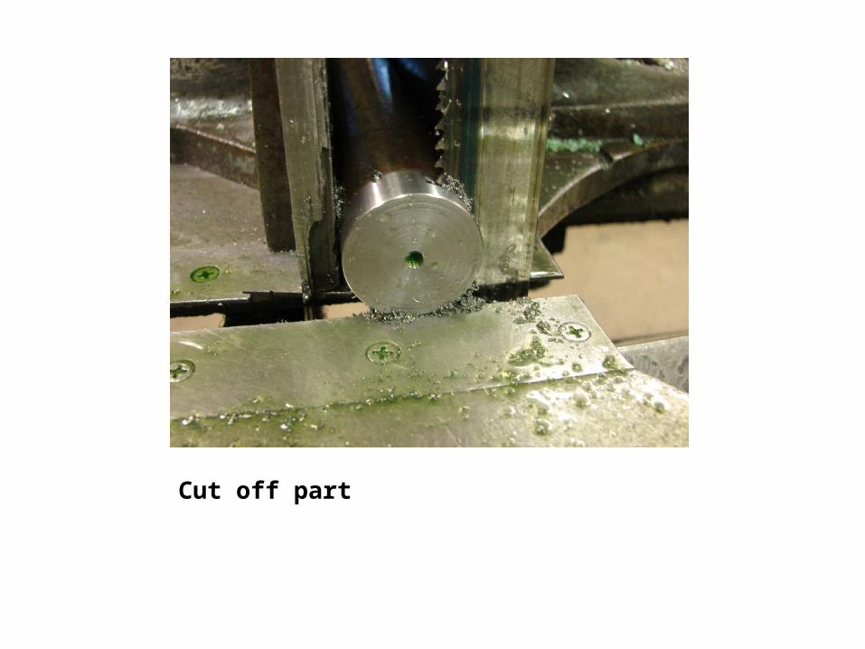
Cut off part