Embed Size (px)
Citation preview

A
dpaoms©
K
1
awsoultdtti
nlmtac
0d
Journal of Power Sources 173 (2007) 367–374
Concentration and ohmic losses in free-breathing PEMFC
Luis Matamoros ∗, Dieter BruggemannLehrstuhl fur Technische Thermodynamik und Transportprozesse, Universitat Bayreuth, 95440 Bayreuth, Germany
Received 17 August 2006; received in revised form 23 January 2007; accepted 24 February 2007Available online 25 April 2007
bstract
Non-isothermal and three-dimensional simulations were carried out to study concentration and ohmic losses in free-breathing PEMFC underiverse conditions. Flow fields, species transport, transport of water in polymer membrane and movement of liquid water in cathode and anodeorous layers were determined. Numerical results were obtained under different hydrating conditions, cell temperatures, cathode catalyst loadingsnd channel lengths. Current density and polymer electrolyte water content distributions as well as average power density were used as main
utput variables to study effects of operative conditions on performance. Results show that slow oxygen transport to active sites constitutes theost limiting factor to consider. Dehydrating conditions slightly affect free-breathing PEMFC performance. The numerical model showed to beuitable to study diverse phenomenon involved in free-breathing PEMFC performance.2007 Elsevier B.V. All rights reserved.
tributi
bplebetdl
cpewaua
eywords: Free-breathing PEMFC; Modeling; Simulation; Current density dis
. Introduction
PEMFCs are usually operated under humidifying conditionsround 80 ◦C to avoid dehydration of polymer electrolyte, reduceater condensation and increase reaction rate. Hence compres-
ors, humidifiers and heaters are needed to achieve high andptimal power densities. Nevertheless, PEMFC may also besed for portable applications in which additional accessoriesike humidifiers and compressors cannot be utilized for prac-ical reasons. Thus optimal performance of these applicationsirectly depends on how species are supplied and disposed inhe membrane and electrode assembly (MEA). Such applica-ions are called “free-breathing” PEMFC provided that oxygens taken from ambient air by diffusion and natural convection.
Performance of free-breathing PEMFC depends highly onatural convection and oxygen diffusion and so concentrationosses become high in comparison to ohmic losses. The slow
otion of reactants and oxygen diffusion are not the only fac-
ors that may cause high limiting effects, low convection maylso result in a build up of water causing severe flooding at theathode.∗ Corresponding author. Tel.: +49 921 557168; fax: +49 921 557165.E-mail address: [email protected] (L. Matamoros).
bsmdttP
378-7753/$ – see front matter © 2007 Elsevier B.V. All rights reserved.oi:10.1016/j.jpowsour.2007.02.091
on; Polymer electrolyte water content
Even though concentration losses in cathode dominate free-reathing PEMFC performance, calculation of water content ofolymer electrolyte and liquid saturation is necessary to estab-ish a complete ohmic-concentration losses analysis. Previousxperimental works concerning free-breathing PEMFC haveeen presented in Refs. [1–12]. Mennola et al. [8] presented bothxperimental and numerical data of oxygen and water mole frac-ion fields as well as velocity fields to provide insight of manyetails that may be important in understanding mass transportimiting controls in free-breathing PEMFC.
Given the small characteristic lengths in PEMFC, numeri-al modelling is important to provide insight into the differenthenomenon and predict distributions that are difficult to bexperimentally determined. Hence the objective of the presentork is to carry out simulations to quantitatively analyze ohmic
nd concentration losses of free-breathing PEMFC power bysing a non-isothermal and three-dimensional model [13] toccount not only for natural convection and oxygen diffusionut also for water and heat management. Flow fields, energy andpecies transport, transport of water in polymer membrane andovement of liquid water in cathode and anode porous layers are
etermined under different hydrating conditions, cell tempera-ures, cathode catalyst loadings and channel lengths, in ordero numerically determine limiting controls of free-breathingEMFC.
368 L. Matamoros, D. Bruggemann / Journal of Power Sources 173 (2007) 367–374
Nomenclature
ARH anode relative humidityC molar concentration (kmol m−3)CRH ambient relative humidityD diffusivity (m2 s−1)F Faraday constantg gravity acceleration (m s−2)H height (m)Kp hydraulic permeability (m2)LL length (m)M molecular weight (kg kmol−1)nGLH2O volumetric condensation rate (kg s−1 m−3)N molar flux (kmol m−2 s−1)Ndrag electro-osmotic drag factor
(kmolH2O(kmolH+ )−1)P pressure (Pa)r reaction rate (kmol s−1 m−3)RH relative humiditys saturationSφ source termT temperature (K)V velocity (m s−1)
Greek lettersβ coefficient of volumetric expansion (K−1)δ thickness (m)λ water content (kmolH2O(kmolSO3
− )−1)μ dynamic viscosity (kg m−1 s−1)� density (kg m−3)
Subscriptsamb ambientc capillaryCL catalyst layerGC gas channelGDL gas diffusion layerH+ protonH2O wateri species iim immobileL liquidm mixtureO2 oxygenSO3
− sulfonate groupT energy
2
secm
aia(cario
2
f
V
wf
∇
∇
∇
w
S
2
mafusion layers and catalyst layers. Pressure drop in anode gas
V momentum
. Model description
As aforementioned, the model is three-dimensional andimultaneously calculates variables of gas channels, catalyst lay-
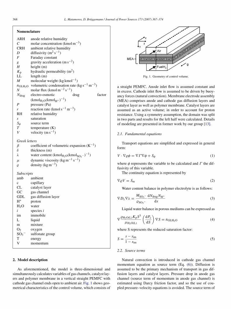
rs and polymer membrane in a vertical straight PEMFC withathode gas channel ends open to ambient air. Fig. 1 shows geo-etrical characteristics of the control volume, which consists ofcep
Fig. 1. Geometry of control volume.
straight PEMFC. Anode inlet flow is assumed constant andn excess. Cathode inlet flow is assumed to be driven by buoy-ncy forces (natural convection). Membrane electrode assemblyMEA) comprises anode and cathode gas diffusion layers andatalyst layer as well as polymer membrane. Catalyst layers aressumed as an active volume; in order to account for protonesistance. Using a symmetry assumption, the domain was splitn two parts and results for the left half were calculated. Detailsf modeling are presented in former work by our group [13].
.1. Fundamental equations
Transport equations are simplified and expressed in generalorm:
· ∇�φ = ∇Γ∇φ + Sφ (1)
here φ represents the variable to be calculated and Γ the dif-usivity of this variable.
The continuity equation is represented by
�V = Sm (2)
Water content balance in polymer electrolyte is as follows:
Dλ∇λ = MSO3−
�SO3−
dNdragNH+
dx(3)
Liquid water balance in porous mediums can be expressed as
�H2O(L)KpS3
μH2O(L)
(dPc
dS
)∇S = nGLH2O (4)
here S represents the reduced saturation factor:
= s − sim
1 − sim(5)
.2. Source terms
Natural convection is introduced in cathode gas channelomentum equation as source term (Eq. (6)). Diffusion is
ssumed to be the primary mechanism of transport in gas dif-
hannel (source term of momentum in anode gas channel) isstimated using Darcy friction factor, and so the use of cou-led pressure–velocity equations is avoided. The source term of

nal of Power Sources 173 (2007) 367–374 369
c
S
dcahc
S
Hr
S
Apor
S
[wca
S
wccb
S
2
odaataoe
�
fco
Table 1Geometrical and electrochemical parameters
Description Value
Channel height (m) 0.003Channel width (m) 0.003Channel length (m) 0.05Channel rib (m) 0.0002Gas diffusion layer thickness (m) 0.0001Gas diffusion layer porosity 0.5Catalyst layer thickness (m) 0.00001Catalyst layer porosity 0.4Polymer membrane thickness (m) 0.00023Pt loading (mgPt cm−2) 1.0Pt surface area (cm2
Pt gPt−1) 250,000
Agglomerate porosity 0.2Agglomerate radii (cm) 0.00001Inlet anode volumetric flow (m3 s−1) 0.0000001Inlet cathode flow pressure (Pa) 101325.0IA
mm
3
apcwifdmm
icatbfarc(
iaeua
L. Matamoros, D. Bruggemann / Jour
ontinuity equation (Eq. (2)) can be ignored [14].
V = �βg(T − Tamb) (6)
Joule heating in the polymer membrane, heat pro-uced in cathode reaction and heat produced inondensation–evaporation entropy change are taken intoccount as source terms of energy ST (Eqs. (7)–(9)). Jouleeating ST1 in the membrane is calculated by using protononductivity in Nafion kH+ and proton flow as follows:
T1 = (NH+F )2
kH+(7)
eat produced by the reaction at the cathode is determined usingeaction heat of oxygen reduction �HrO2 and reaction rate:
T2 = �HrO2rO2 (8)
nd condensation–evaporation entropy change in cathodeorous mediums is estimated using latent heat of vaporizationf water at local temperature HLG and volumetric condensationate:
T3 = HLGnGLH2O (9)
Agglomerate model was used as electrochemical model15–19]. The group of agglomerate model equations used in thisork has been previously described in Ref. [13]. Electrochemi-
al reaction rate obtained from agglomerate model is considereds source term of species Si in catalyst layers:
i = Miri (10)
Stiochiometrical factors of every species are derived from theell-known mechanism of reaction in PEM fuel cells. Finally,
ondensation and evaporation processes in porous mediums areonsidered as an additional source term for the water to gasalance:
H2O = nGLH2O (11)
.3. Boundary conditions
In order to determine interfacial water transfer between cath-de and anode porous mediums and the polymer membrane, theifference between bulk concentrations of water in each phasend equilibrium concentrations of water in the interface is useds the driving force of absorption and desorption of water byhe polymer electrolyte. Convective mass transfer is neglected,nd so water exchange is expressed in terms of molar fractionf each phase (Yi and Xi) and mixture diffusivity of species i byach phase (Di,m1 and Di,m2):
1Di,m1Xi − X∗
i
M1�x1= �2Di,m2
Y∗i − Yi
M2�x2(12)
The equilibrium data from Springer et al. [20] at 30 ◦C androm Hinatsu et al. [21] at 80 ◦C are used to complete this interfa-ial mass transfer model by relating the molar fraction of waterf each phase at the interface (Y∗
i and X∗i ). It is important to
ooit
nlet anode flow pressure (Pa) 300000.0mbient temperature (◦C) 25
ention that liquid water uptake from cathode and anode porousediums is assumed as negligible.Gas channel walls are assumed isothermal.
. Results and discussion
Average current density and polymer membrane voltage losslong-channel distributions as well as average power density areresented as main output variables to study effects of operativeonditions on free-breathing PEMFC performance. Simulationsere carried out to observe influences of ambient and anode
nlet flow relative humidity as well as cell temperature onree-breathing PEMFC power. Additionally, calculations usingifferent cathode catalyst loadings and channel lengths wereade to study concentration losses behavior when improvingass transfer and electrochemical conditions.Even though modeling is non-isothermal, cell temperature
s defined as an input variable. The input value that representsell temperature is assumed equal to wall temperature, which isssumed constant as mentioned above. Such assumption showedo be suitable, given that temperature gradient can be neglected,asically due to small geometry and low current densities underree-breathing conditions. Moreover, inlet anode flow temper-ture is assumed equal to cell temperature, and so numericalesults of temperature become almost uniform, even thoughathode inlet flow temperature is constant in all calculations25 ◦C).
Table 1 summarizes geometrical, electrochemical and operat-ng parameters arbitrarily used in this work. Both current densitynd cell potential are considered output variables. Therefore,very input variable was kept constant except for the variablender study. As mentioned above, catalyst layers are assumeds an active volume, and so cathode overpotential becomes an
utput variable due to proton resistance. Hence, input cathodeverpotential at the cathode catalyst layer–polymer membranenterface must be defined, in order to estimate ohmic losses inhe cathode catalyst layer. This reference cathode overpotential
370 L. Matamoros, D. Bruggemann / Journal of Power Sources 173 (2007) 367–374
Fa
iaaBbbieTboip
3
cp1wA
p07oniCshidToob
Fa
cattthc
s0iatstFng0tocvtpmt(db
dah
ig. 2. Along channel current density for different ambient relative humiditiest 25 ◦C.
s assumed constant (0.8 V under electrochemical conditionsrbitrarily chosen in this work). Catalyst loading is assumeds 1.0 mg cm−2 and catalyst surface area as 250,000 cm2 g−1.oth values may provide relative good performance under free-reathing conditions, and so current density distributions maye suitable to study cell output under diverse conditions. It ismportant to mention that both values do not represent optimallectrode characteristics, because they were arbitrarily chosen.o analyze optimal electrode characteristics the relationshipetween catalyst loading and surface area should be defined inrder to carry out numerical studies concerning catalyst load-ng in free-breathing PEMFC. Such task is not an objective ofresent work.
.1. Effect of humidity conditions
As oxygen is directly taken from surrounding air, ambientonditions may have an influence on free-breathing PEMFCerformance. Ambient relative humidity is taken as 40, 70 and00% at 25 ◦C for different cell temperatures (25, 50 and 75 ◦C)hile anode inlet flow is assumed to be fully humidified (100%RH) at cell temperature.Adjusting cell temperature at 25 ◦C (gas channel walls tem-
erature), average power density is 0.585 V–0.0245 W cm−2,.586 V–0.0251 W cm−2 and 0.586 V–0.0244 W cm−2 for 40,0 and 100% air relative humidity, respectively. In this casexygen supply is rather small, given that natural convection isegligible and diffusion through ends of cathode gas channels the unique supply of oxidant for electrochemical reaction.urrent density is rather low as a result of slow diffusion, and
o cell potential is almost constant for every ambient relativeumidity. As shown in Fig. 2, concentration losses highly dom-nate performance under these conditions, given that currentensity curves overlap for different ambient relative humidities.
herefore ambient relative humidity exerts a negligible effect onhmic losses as result of low current densities yielded under suchxygen transfer control, and so power output is only governedy oxygen diffusion. Most of oxygen is consumed near ends ofdmoc
ig. 3. Along channel current density for different ambient relative humiditiest 50 ◦C.
athode gas channel and so average power density becomes lownd highly controlled by oxidant transport. A considerable por-ion of the active area is barely used due to poor axial oxidantransport against through-plane diffusion and activation poten-ial. Highest current densities at ends of cathode gas channelaving almost symmetrical magnitudes are product of negligibleonvection and oxygen diffusion through boundaries.
At 50 ◦C of cell temperature, average power den-ity is 0.567 V–0.0451 W cm−2, 0.564 V–0.0454 W cm−2 and.569 V–0.0460 W cm−2 for 40, 70 and 100% air relative humid-ty, respectively. Considering that cell temperature is higher thanmbient temperature, natural convection yields a smooth streamhrough cathode gas channel improving oxygen supply and asuch the performance of the cell. The average inlet air velocityhrough gas channel is 0.017 m s−1. As it can be observed inig. 3, highest current density is seen at entrance of gas chan-el. Oxygen is rapidly consumed by electrochemical reactioniven the high activation potential needed to operate around.6 V. Presence of natural convection improves performance dueo major availability and transport of oxidant in comparison tonly-diffusion-driven-flux and then current density increases inomparison to former case (Fig. 2). Even though natural con-ection enhances oxygen supply, the cathode reaction seemso be highly controlled by concentration losses, given that cellotential is almost constant for every air relative humidity, whicheans that ohmic losses may be negligible under these condi-
ions. At upper end of gas channel, oxygen counter-diffusionagainst natural convection) yields a slight increment of currentensity as product of the short path between gas channel endoundary and active sites of cathode catalyst layer.
Increasing the cell temperature to 75 ◦C, average powerensity is 0.561 V–0.0633 W cm−2, 0.561 V–0.0629 W cm−2
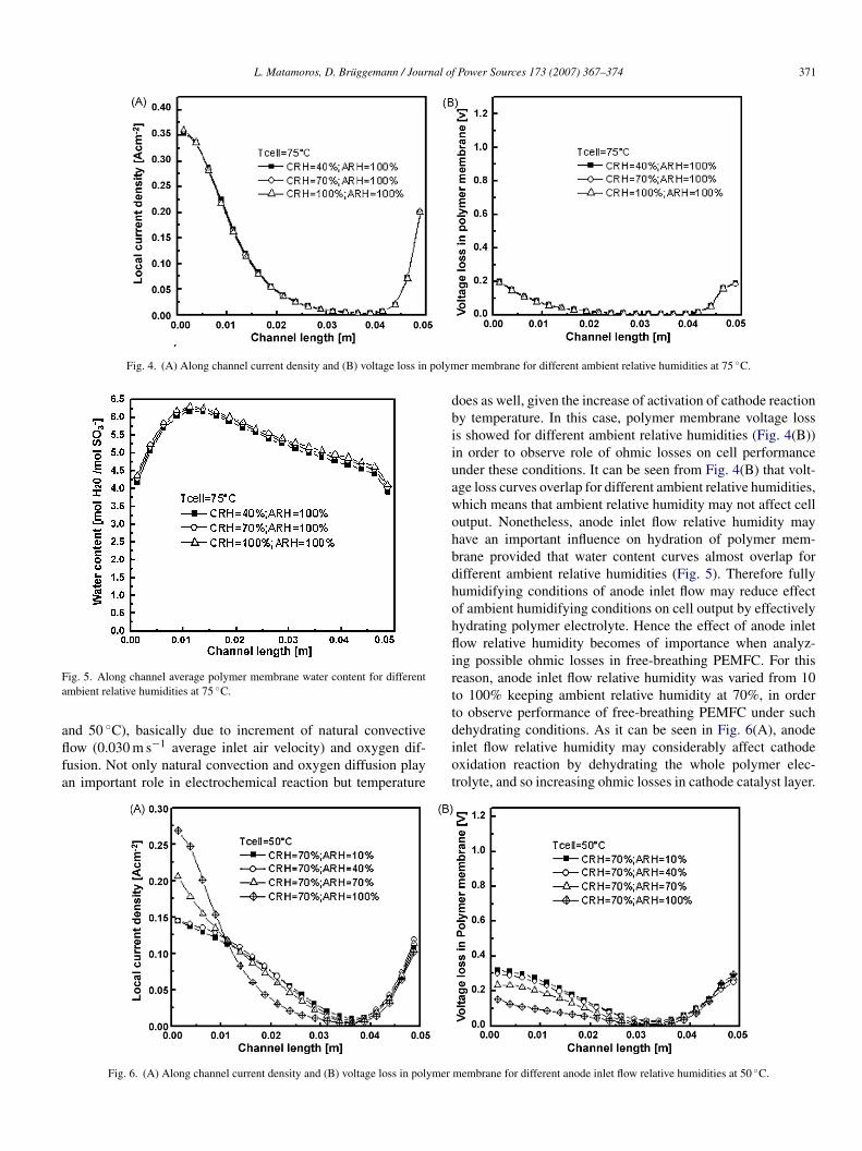
nd 0.561 V–0.0625 W cm−2 for 40, 70 and 100% air relativeumidity, respectively. Fig. 4(A) shows overlapping curves for
ifferent ambient relative humidities, which means that perfor-ance is even highly controlled by mass transport deficienciesver possible dehydration of polymer electrolyte. Nevertheless,urrent densities increase in comparison to former cases (25
L. Matamoros, D. Bruggemann / Journal of Power Sources 173 (2007) 367–374 371
Fig. 4. (A) Along channel current density and (B) voltage loss in polym
Fa
aflfa
dbiiuawohbdhohflirtt
ig. 5. Along channel average polymer membrane water content for differentmbient relative humidities at 75 ◦C.
◦
nd 50 C), basically due to increment of natural convectiveow (0.030 m s−1 average inlet air velocity) and oxygen dif-usion. Not only natural convection and oxygen diffusion playn important role in electrochemical reaction but temperaturediot
Fig. 6. (A) Along channel current density and (B) voltage loss in polymer
er membrane for different ambient relative humidities at 75 ◦C.
oes as well, given the increase of activation of cathode reactiony temperature. In this case, polymer membrane voltage losss showed for different ambient relative humidities (Fig. 4(B))n order to observe role of ohmic losses on cell performancender these conditions. It can be seen from Fig. 4(B) that volt-ge loss curves overlap for different ambient relative humidities,hich means that ambient relative humidity may not affect cellutput. Nonetheless, anode inlet flow relative humidity mayave an important influence on hydration of polymer mem-rane provided that water content curves almost overlap forifferent ambient relative humidities (Fig. 5). Therefore fullyumidifying conditions of anode inlet flow may reduce effectf ambient humidifying conditions on cell output by effectivelyydrating polymer electrolyte. Hence the effect of anode inletow relative humidity becomes of importance when analyz-
ng possible ohmic losses in free-breathing PEMFC. For thiseason, anode inlet flow relative humidity was varied from 10o 100% keeping ambient relative humidity at 70%, in ordero observe performance of free-breathing PEMFC under such
ehydrating conditions. As it can be seen in Fig. 6(A), anodenlet flow relative humidity may considerably affect cathodexidation reaction by dehydrating the whole polymer elec-rolyte, and so increasing ohmic losses in cathode catalyst layer.membrane for different anode inlet flow relative humidities at 50 ◦C.
372 L. Matamoros, D. Bruggemann / Journal of Power Sources 173 (2007) 367–374
ass fra
EpcfdouoEstd07ff0
3
ftaccsmrco
pnftaataata
vdigdfFtgttiTte
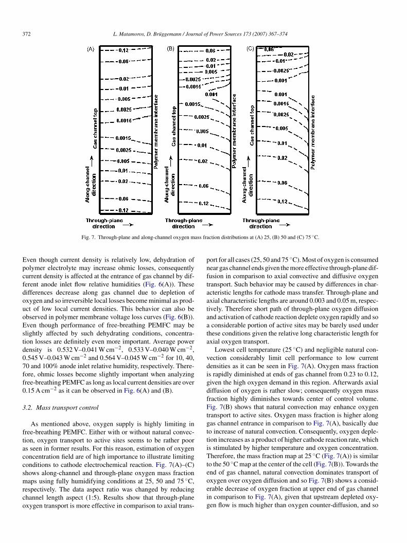
Fig. 7. Through-plane and along-channel oxygen m
ven though current density is relatively low, dehydration ofolymer electrolyte may increase ohmic losses, consequentlyurrent density is affected at the entrance of gas channel by dif-erent anode inlet flow relative humidities (Fig. 6(A)). Theseifferences decrease along gas channel due to depletion ofxygen and so irreversible local losses become minimal as prod-ct of low local current densities. This behavior can also bebserved in polymer membrane voltage loss curves (Fig. 6(B)).ven though performance of free-breathing PEMFC may belightly affected by such dehydrating conditions, concentra-ion losses are definitely even more important. Average powerensity is 0.532 V–0.041 W cm−2, 0.533 V–0.040 W cm−2,.545 V–0.043 W cm−2 and 0.564 V–0.045 W cm−2 for 10, 40,0 and 100% anode inlet relative humidity, respectively. There-ore, ohmic losses become slightly important when analyzingree-breathing PEMFC as long as local current densities are over.15 A cm−2 as it can be observed in Fig. 6(A) and (B).
.2. Mass transport control
As mentioned above, oxygen supply is highly limiting inree-breathing PEMFC. Either with or without natural convec-ion, oxygen transport to active sites seems to be rather poors seen in former results. For this reason, estimation of oxygenoncentration field are of high importance to illustrate limitingonditions to cathode electrochemical reaction. Fig. 7(A)–(C)hows along-channel and through-plane oxygen mass fraction
aps using fully humidifying conditions at 25, 50 and 75 ◦C,espectively. The data aspect ratio was changed by reducinghannel length aspect (1:5). Results show that through-planexygen transport is more effective in comparison to axial trans-
oeig
ction distributions at (A) 25, (B) 50 and (C) 75 ◦C.
ort for all cases (25, 50 and 75 ◦C). Most of oxygen is consumedear gas channel ends given the more effective through-plane dif-usion in comparison to axial convective and diffusive oxygenransport. Such behavior may be caused by differences in char-cteristic lengths for cathode mass transfer. Through-plane andxial characteristic lengths are around 0.003 and 0.05 m, respec-ively. Therefore short path of through-plane oxygen diffusionnd activation of cathode reaction deplete oxygen rapidly and soconsiderable portion of active sites may be barely used under
hese conditions given the relative long characteristic length forxial oxygen transport.
Lowest cell temperature (25 ◦C) and negligible natural con-ection considerably limit cell performance to low currentensities as it can be seen in Fig. 7(A). Oxygen mass fractions rapidly diminished at ends of gas channel from 0.23 to 0.12,iven the high oxygen demand in this region. Afterwards axialiffusion of oxygen is rather slow; consequently oxygen massraction highly diminishes towards center of control volume.ig. 7(B) shows that natural convection may enhance oxygen
ransport to active sites. Oxygen mass fraction is higher alongas channel entrance in comparison to Fig. 7(A), basically dueo increase of natural convection. Consequently, oxygen deple-ion increases as a product of higher cathode reaction rate, whichs stimulated by higher temperature and oxygen concentration.herefore, the mass fraction map at 25 ◦C (Fig. 7(A)) is similar
o the 50 ◦C map at the center of the cell (Fig. 7(B)). Towards thend of gas channel, natural convection dominates transport of
xygen over oxygen diffusion and so Fig. 7(B) shows a consid-rable decrease of oxygen fraction at upper end of gas channeln comparison to Fig. 7(A), given that upstream depleted oxy-en flow is much higher than oxygen counter-diffusion, and so
L. Matamoros, D. Bruggemann / Journal of Power Sources 173 (2007) 367–374 373
ge los
loscE7afpc
nFpcltb
i
Fa
cicedbdoio
attPad
Fig. 8. (A) Along channel current density and (B) volta
ower oxygen mass fraction is observed. Even so, performancef cell increases at higher temperatures. Fig. 7(C) showed to beimilar to (B), even though temperature is higher, and so oxygenonsumption. This effect is explained by former observation.ven though natural convection and diffusion are enhanced at5 ◦C in comparison to 50 ◦C, cathode reaction rate is also highernd so oxygen depletion. As mentioned before, a lower oxygenraction at upper end of gas channel (Fig. 7(B) and (C)) is aroduct of higher oxygen depleted upstream in comparison toounter-diffusion.
As seen cell temperature affects performance by increasingatural convection, oxygen diffusion and activation potential.ig. 8(A) and (B) illustrate the role of temperature on cell out-ut under fully humidifying conditions. Cell performance canonsiderably be increased using higher temperatures (A). Ohmicosses show a negligible effect on cell output (B), which meanshat concentration losses govern cell performance under free-
reathing conditions.Under such mass transport limitations, cathode catalyst load-ng may be an important parameter to observe. Fig. 9 shows
ig. 9. Along channel current density using different cathode catalyst loadingst 50 ◦C.
msud
F
s in polymer membrane for different cell temperatures.
urrent densities distribution for different cathode catalyst load-ngs (1.0, 2.5, 5.0 and 10 mg cm−2). As it can be seen in Fig. 9,athode catalyst loading enhances current density at gas channelnds. However this effect diminishes for higher catalyst loading,ue to poor axial diffusion. Differences in current density distri-utions dramatically decrease along the gas channel, as result ofepletion of oxygen which exclusively dominates performancever increase of active sites. Therefore increasing catalyst load-ng under such mass transfer controls may represent a high lossf cathode reaction efficiency.
Considering such limitations of axial oxygen transport, cellxial length is reduced to observe improvements in oxygenransport and overall performance. Results of Figs. 7–9 showedhat cathode feed may be rather slow, and so free-breathingEMFC performance is rather limited by rapid oxygen depletiont electrical potential around 0.6 V. Fig. 10 shows current densityistributions using different channel lengths. As it can be seen,agnitudes of average current density are highly different due to
horter axial diffusion path, and so the active area becomes bettertilized under chosen conditions. At end of gas channel, currentensity varies as product of upstream oxygen flow which is not
ig. 10. Along channel current density using different channel lengths at 75 ◦C.

3 nal of
deHcc
olm
r
wto
C
Te
CfcbTbtp
4
iTcPdbiwaimlesurdciP
yeTia
fgdaad
maocae
tlp
R
[
[
[[[[[
[[
[
74 L. Matamoros, D. Bruggemann / Jour
epleted for shorter gas channels. End current density is small-st for longest channel, given the depletion of oxygen upstream.owever, once channel length is shorter, oxygen upstream and
ounter-diffusion yield higher current densities towards end ofhannel.
A simple approach can be made, in order to demonstrate rolef natural convection over oxygen diffusion on concentrationosses. Cathode reaction rate may be assumed as a first order
echanism, in order to simplify the analytic expression:
O2 = K1CCLO2
e−(K2/T ) (13)
here K1 and K2 represent cathode kinetic constants. Concen-ration of oxygen in cathode catalyst layer can be related toxygen concentration at inlet as follows:
CLO2
= CO2inlet
[1+K1 e−(K2/T )((δGDL/DO2,m)+(LLGC/HGCVinlet))](14)
erms that represent oxygen transport to active sites in formerxpression (Eq. (14)) are
δGDL
DO2,m+ LLGC
HGCVinlet(15)
onvective term (right) is around 1000 times higher than dif-usive term (left) at 50 and 75 ◦C, which means that oxygenoncentration in cathode catalyst layer is basically governed byehavior of natural convection under conditions of this work.herefore, the role of temperature on oxygen diffusion may note of importance when analyzing concentration losses, givenhat axial oxygen transport dominates free-breathing PEMFCerformance.
. Conclusions
Use of numerical tools is highly important to predict behav-ors and distributions that are experimentally difficult to obtain.herefore present work is useful to understand phenomenononcerning ohmic and concentration losses of free-breathingEMFC power. Given the difficulties of obtaining experimentalata to properly validate CFCD modeling and properties distri-utions, a simple comparison between I–V curves was maden former work [13] to ensure that this numerical modelingas suitable for studying ohmic and concentration losses. The
uthors in [13] mentioned that polarization curves are highlynfluenced by electrochemical reaction constants at low and
oderate current densities and by ohmic and concentrationosses at high current densities. A future goal is to comparexperimental and numerical distributions to improve under-tanding of phenomenon that govern performance of PEMFCnder different conditions. Wang [22] presented a detailedeview of diverse works concerning measurements of current
ensity distributions which may be used, together with numeri-al results, to yield an analysis concerning main limiting factors,n order to enhance understanding of processes involved inEMFC.[
[
[
Power Sources 173 (2007) 367–374
In this work results showed that dehydrating conditions mayield considerable ohmic losses only if oxygen transport is highnough to produce average current densities over 0.15 A cm−2.herefore use of fully humidified anode inlet flows would
mprove free-breathing PEMFC performance in case of oper-ting at moderate current densities (>0.15 A cm−2).
Concentration losses dominate free-breathing PEMFC per-ormance. Axial oxygen transport constitutes main power loss,iven that oxidant inlet flux is driven by natural convection andiffusion, which may be considered as slow transport mech-nisms in comparison to forced convection. Therefore oxygenvailability in active sites is highly limited and as such so currentensity.
Under conditions arbitrarily used to obtain numerical results,ost of active area was barely utilized, given the unbal-
nced relation between axial transport of oxygen and activationf cathode reaction. Then considering such oxygen transportontrol, channel length constitutes an important parameter toccount for, because most of reaction may take place at channelnds.
Considering high oxygen transport resistance in comparisono activation potential, only small amounts of cathode catalystoadings are needed to yield acceptable free-breathing PEMFCerformances.
eferences
[1] D. Chung, R. Jiang, J. Power Sources 83 (1999) 128–133.[2] S. Morner, S.A. Klein, J. Solar Energy Eng. 123 (2001) 225–231.[3] M. Noponen, T. Mennola, M. Mikkola, T. Hottinen, P. Lund, J. Power
Sources 106 (2002) 304–312.[4] M. Noponen, T. Hottinen, T. Mennola, M. Mikkola, P. Lund, J. Appl.
Electrochem. 32 (2002) 1081–1089.[5] T. Mennola, M. Mikkola, M. Noponen, T. Hottinen, P. Lund, J. Power
Sources 112 (2002) 261–272.[6] P.W. Li, T. Zhang, Q.M. Wang, L. Schaefer, M.K. Chyu, J. Power Sources
114 (2003) 63–69.[7] T. Hottinen, M. Noponen, T. Mennola, O. Himanen, M. Mikkola, P. Lund,
J. Appl. Electrochem. 33 (2003) 265–271.[8] T. Mennola, M. Noponen, M. Aronniemi, T. Hottinen, M. Mikkola, O.
Himanen, P. Lund, J. Appl. Electrochem. 33 (2003) 979–987.[9] A. Schmitz, S. Wagner, R. Hahn, H. Uzun, C. Hebling, J. Power Sources
118 (2003) 162–171.10] T. Mennola, M. Noponen, T. Kallio, M. Mikkola, T. Hottinen, J. Appl.
Electrochem. 34 (2004) 31–36.11] A. Schmitz, S. Wagner, R. Hahn, H. Uzun, C. Hebling, J. Power Sources
127 (2004) 197–205.12] T. Hottinen, M. Mikkola, P. Lund, J. Power Sources 129 (2004) 68–72.13] L. Matamoros, D. Bruggemann, J. Power Sources 161 (2006) 203–213.14] Y. Wang, C.-Y. Wang, J. Electrochem. Soc. 152 (2) (2005) A445–A453.15] K. Broka, P. Ekdunge, J. Appl. Electrochem. 27 (1997) 281–289.16] M.L. Perry, J. Newman, E.J. Cairns, J. Electrochem. Soc. 145 (1) (1998)
5–15.17] C. Marr, X. Li, J. Power Sources 77 (1999) 17–27.18] F. Jaouen, G. Lindbergh, G. Sundholm, J. Electrochem. Soc. 149 (4) (2002)
A437–A447.19] Q. Wang, D. Song, T. Navessin, S. Holdcroft, Z. Liu, Electrochem. Acta
50 (2004) 725–730.
20] T.E. Springer, T.A. Zawodzinski, S. Gottesfeld, J. Electrochem. Soc. 138(8) (1991) 2334–2342.21] J.T. Hinatsu, M. Mizuhata, H. Takenata, J. Electrochem. Sources 141 (6)
(1994) 1493–1498.22] C.-Y. Wang, Chem. Rev. 104 (10) (2004) 4727–4766.