Embed Size (px)
DESCRIPTION
Computer Networks (EENG 4810). Course Objectives & Scope. In this class, you are expected to learn -. A brief History of Computer Networks Categorization of Computer Networks Network Services and Internet Perspective Network Components- Nuts and Bolts View - PowerPoint PPT Presentation
Citation preview

Computer Networks- Course Objectives & Scope - 1
1
Computer Networks (EENG
4810)
Computer Networks- Course Objectives & Scope - 2
2
Course Objectives & Scope
Computer Networks- Course Objectives & Scope - 3
3
In this class, you are expected to learn -
A brief History of Computer Networks
Categorization of Computer Networks
Network Services and Internet Perspective
Network Components- Nuts and Bolts View
General Concepts of Network Design
Protocols and Layered Communication Architecture
Network Programming
Computer Networks- Course Objectives & Scope - 4
4
This class, however, does not deal with -
Network Hardware Design
Comparative analyses of different protocol standards
Special purpose networks such as ad hoc sensor nets
Applications of Queuing Theory to Network traffic control

5
Lesson 1:History of Computer
Networks

History of Computer Networks - 1 6
Preview of the Lesson 1
In this lesson, we cover History of Computer Networks organized into approximately 5 decades.
In passing, we get a hang of what all a computer network can do

History of Computer Networks- 2 7
History of Computer Networks
Development of Packet Switching: 1961-72
Proprietary Networks and Internetworking: 1972-80
Proliferation of Networks: 1980-90
Internet Explosion: 1990-2000
Developments of Last Decade: Bubble burst? Social Networks?
Lesson 1: History of Computer Networks - 3
8
Development of Packet Switching: 1961-72
Telephone network - World’s dominant communication network , uses circuit switching. (Early 1960s)Three research groups around the world independently invented packet switching (1964 – 1967)
Leonard Kleinrock at MIT used queuing theory to demonstrate effectiveness of packet switching for bursty trafficPaul Baran of Rand Institute investigated packet switching for secure voice communication over military networksDonald Davies and Roger Scantlebury were developing ideas on packet switching at the National Physical Lab, England.
Lesson 1: History of Computer Networks - 4
9
Development of Packet Switching: 1961-72
(continued)J.C.R. Licklider and Laurence Roberts led the CS program at ARPA (Advanced Projects Research Agency) and published a plan for ARPAnet in 1967.Arpanet was the ancestor of today’s Internet.Early Packet switches were known as Interface Message Processors (IMPs). BBN got the contract.First IMP was installed at UCLA on Labor Day 1969 under Kleinrock’s supervision. Later 3 more at SRI, UCSB and University of Utah.
Lesson 1: History of Computer Networks - 5
10
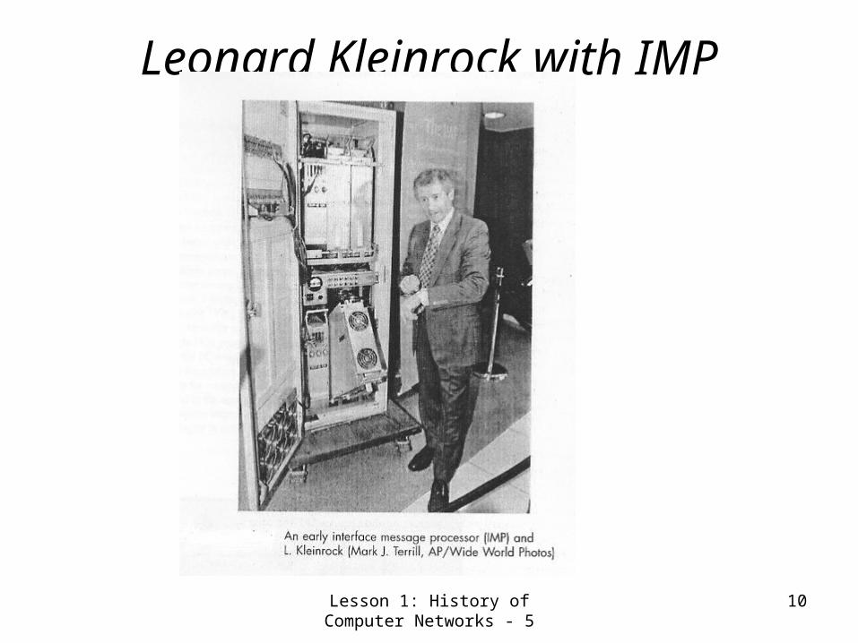
Leonard Kleinrock with IMP

Lesson 1: History of Computer Networks - 6
11
Development of Packet Switching: 1961-72
(continued)First use of the net of 4 nodes was remote login from UCLA to SRI; it resulted in system crash.Robert Kahn demonstrated 15-node ARPAnet in 1972 ICCN. First host to host protocol was Network Control Protocol (NCP). Ray Tomlinson at BBN wrote the first e-mail program in 1972.

History of Computer Networks - 7 12
Proprietary Networks and Internet 1972-80
ALOHAnet- microwave satellite net linking universities on Hawaii islands (Norman Abramson 1970).
Telenet- a BBN commercial packet network and Cyclades- a French Packet Net by Louis Pouzin.
Time-sharing networks such as Tymnet and GE Information Services Net (late 60s and early 70s).
Metcalfe’s PhD thesis proposing Ethernet.

History of Computer Networks - 8 13
Proprietary Networks and Internet 1972-80
(Continued)Proprietary Networks such asIBM’s (1969-74) System Network Architecture (SNA) paralleling the ARPAnet (Schwartz 1977).DEC’s DECnet and Xerox corporation’s XNA.
Vincent Cerf and Robert Kahn (Cerf 1974)- Architecture for interconnecting Networks (They coined the word Internet for network of networks).DARPA’s packet satellite and packet-radio networks (Kahn 1978).

History of Computer Networks - 9 14
Proprietary Networks and Internet 1972-80
(Early Internet Features)Cerf and Kahn’s TCP (quite different from now)It combined reliable in-sequence delivery of data by end-system retransmission (as now) with forwarding (as IP now)Realization of usefulness of separation of unreliable, non-flow controlled end-to end transport service for applications such as packetized voice led to separation of IP.Three internet protocols TCP, IP and UDP - conceptually in place by the end of 1970’s.
Main features of their InterNet- Minimalism, autonomy (no internal changes required for interconnection), Best effort delivery, stateless routers and decentalized control.

Lesson 1: History of Computer Networks - 10
15
Proprietary Networks and Internet 1972-80
(Early Ethernet Features)Abramson’s ALOHA protocol- a multiple-access protocol for communication among geographically distributed users by a single shared broadcast medium.Metcalfe and Bogg’s EtherNet protocol for wire-based shared networks was originally motivated by the need to connect multiple PCprinters

History of Computer Networks - 11
16
Proliferation of Networks 1980-90
100 nodes by late 70’s New national networks (100,000 by the end of 80’s)
BITNET for email and FTP services among many North East UniversitiesCSNET (computer Science Network) for researchers with no access to APRPAnet.NSF-net for access to NSF-sponsored super-computing centers
Starting with a backbone of 56 kbps, NSF net was running at 1.5 Mbps by the end of the decade.
Lesson 1: History of Computer Networks - 12
17
Proliferation of Networks 1980-90 (Continued)
Simple Message Transfer Protocol (SMTP): E-Mail 1982Deployment of TCP /IP replacing NCP (Jan. 1, 1983)FTP- The File Transfer Protocol defined (1983).Host-based TCP Congestion Control (Jacobson 1988).Domain Name System (DNS)- mapping between human readable Internet computer name and 32-bit IP address.
Lesson 1: History of Computer Networks - 14
18
Proliferation of Networks 1980-90
(The Minitel Project)French Minitel project paralleling ARPAnet
Ambitious projest sponsored by the French GovernmentX.25 protocol suite using virtual circuitsBy mid-90’s, it offered more than 20, 000 services- from home banking to research databaseUsed by more than 20% of the populationGenerated over $1 billion in revenueWas in most French homes 10 years before Americans had ever heard of the Internet.

History of Computer Networks -15 19
Internet Explosion: The1990sEarly 90’s Arpanet decommissioned as Milnet
and Defense Data Net grew enough to carry all defense-related traffic.NSF lifted restrictions on commercial use of NSFnet (1991). NSFnet began to serve as a backbone and was later decommissioned it in 1995.Web invented at CERN by Tim Berners-Lee (89-91)
Developed intial versions of HTML, HTTP, a web server and a web browser - Based on the original work on Hypertext in 1940s by Bush (1945) and in 1960s by Ted Nelson
Marc Andreesen developed Mosaic- Popular GUI browser.

History of Computer Networks -16 20
Internet Explosion: First half of1990s
Marc Andreesen and Jim Clark formed Mosaic Communications in 1994(it later became Netscape).
By 1995, University students were able surf web.
Big and small companies started transacting on the web and transact commerce over the web.

History of Computer Networks -17 21
Internet Explosion: Second half of1990sMicrosoft (MS) started making browsers (1996)
and this started the war with NetScape which MS won later.E-mail evolved with address books, attachments, hot links, multimedia support. 4 Killer applications
Web accessible emailWeb browsing & internet commerceinstant messaging with contact lists pioneered by ICQpeer-to-peer file sharing of MP3s , pioneered by Napster .
By late 90’s, 50 million computers with 100+ million users on the web. 1 GBs Back bone link speeds achieved.
History of Computer Networks -18 22
Developments of Last DecadeFinancial turmoil, many start-ups collapsed. Still many companies like eBay, Yahoo, Amazon and Cisco emerged as winners despite setbacks in their stock prices.Advances in content distribution, internet telephony, high speed LANs and fast routers3 Important developments
High Speed Access Internet Access (Cable/DSL/Wireless LANs)Secure applicationsP2P (Point-to-point Networking)

History of Computer Networks -19 23
Three Important Recent Developments
I- High Speed Internet AccessIncreased penetration of broadband residential Internet via Cable and DSL with applications such as high-quality Video on Demand and high quality Video ConferencingIncreased ubiquity of public Wi-Fi nets (with 11 Mbps and higher speeds)Internet access via mobile phones of 3rd Generation & Beyond; proliferation of social networks

History of Computer Networks -20 24
Three Important Recent Developments
II- SecurityIntrusion detection methods for early warning of denial of service attacks through worms (e.g. Blaster worm) that infect systems and clog networks.
Use of Firewalls to filter unwanted traffic before it enters the network.
Use of IP-traceback to pinpoint the origin of attacks.

History of Computer Networks -21 25
Three Important Recent Developments
III- P2P NetworkingP2P application exploits resources (memory, disk-space, content and CPU cycles) in user’s computers.
It gives significant autonomy from central servers.
KaZaA is the most popular p2P-file sharing system.
Currently, this network has 4 million connected systems and its traffic constitutes 20-50% of Internet traffic.

History of Computer Networks - 22
26
Summary and Follow-upIn this lesson, we covered History of Computer Networks organized into approximately 5 decades.In passing, we found what all a computer networks can do. This will help you to write the first chapter of your project report i.e. to prepare a table of requirements for your own network!You got used to some terminology e.g. circuit switching, packet switching, firewalls, etc. If any of those concepts are not clear, you may search the web, discuss with me or wait on till we take them up in a greater detail later.Explore the concepts- Circuit/Virtual Circuit/Packet switching on the web.

27
Lesson 2:Overview of Computer
Networks

Overview of Computer Networks - 1
28
Preview of the Lesson 2In this lesson, we try to answer the question- What is a Computer Network?
We try to view computer networks from different perspectives. In other words, we try to answer the question: what are all the different types computer networks?We will have an overview of different components of a computer network (Internet).
We also study a little bit of how the interconnected computers communicate with one another, that is, we will have cursory glance at protocol stacks.
Overview of Computer Networks - 2
29
Computer Networks- Definition & PerspectivesReference:
http://en.wikipedia.org/wiki/Computer_network What is a Computer Network?A system for communication among two or more
computers.
What are all the different types computer networks?
Different ways of categorization of Computer networks are:
– Range or extent of the network– Inter-nodal functional relationship– Network Topology– Specialized functions of the nodes
Overview of Computer Networks - 3
30
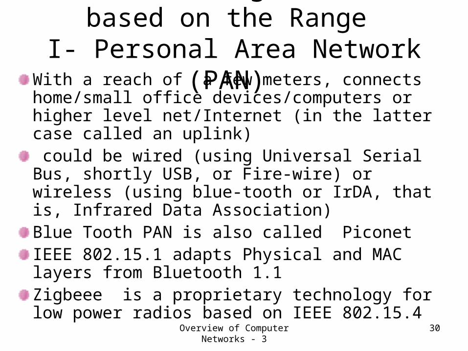
Network Categorization based on the Range
I- Personal Area Network (PAN) With a reach of a few meters, connects home/small office devices/computers or higher level net/Internet (in the latter case called an uplink) could be wired (using Universal Serial Bus, shortly USB, or Fire-wire) or wireless (using blue-tooth or IrDA, that is, Infrared Data Association)Blue Tooth PAN is also called Piconet IEEE 802.15.1 adapts Physical and MAC layers from Bluetooth 1.1 Zigbeee is a proprietary technology for low power radios based on IEEE 802.15.4

Overview of Computer Networks - 4
31
Network Categorization based on the Range
II - Local Area Network (LAN)Range is less than 1000 m2
Could be used in home, small office or university.
Earlier popular LAN was proprietary - DataPoint’s ArcNet
IEEE later produced two LAN standards- Ether Net (IEEE 802.3) and Token Ring (IEEE 802.5)LAN speeds could be 10/100 Mbps (Ether Net) and 4/16/100 mbps/1 Gbps (Token Ring)
Wireless LANs- IEEE 802.11 (Wi-Fi)- speeds up to 56 Mbps

Overview of Computer Networks - 5
32
Network Categorization based on the Range
III - Metropolitan Area Network (MAN)Spans a city or a big campus with range up to 200
km (125 miles)Earlier technologies used for MANs were:
Fiber Distributed Data Interface (FDDI)Switched Megabit Data Service (as defined by IEEE 802.6 MAN standard) using either B-ISDN or Distributed Dual-Queue Dual Bus (DQDB) with speeds 1.5/45 Mbs.Asynchronous Transfer Mode (ATM)
Above technologies are being displaced by 1GB Ether Net based MansMAN links between LANs and WANs are usually microwave/ infra-red/radio.

Overview of Computer Networks - 6
33
Network Categorization based on the Range
IV - Wide Area Network (WAN)Covers wide geographical areas spanning multiple cities.Works on leased lines and connects multiple LANsUses protocols such as TCP/IP, x.25, Frame Relay and ATMUsually used to connect different sites of an organization or service provider. For this reason, it is being replaced by Virtual Private Networks (VPNs).VPNs are of two types- i) Secure (they use leased lines and use protocols like IPSEC ii) Trusted (They rely on security of single provider’s network and use protocols such as Multi-protocol label switching (MPLS) and Layer 2 Tunneling Protocol (L2TP)

Overview of Computer Networks - 7
34
Network Categorization based on the Functional Relationship
of the Nodes
Client- Server Network
Multi-tier architecture (GUI, business logic and DB could be in 3 separate tiers)
Peer-to-Peer Network (each node acts as both a client and server, e.g. in case of e-mail).

Overview of Computer Networks - 8
35
Network Categorization based on the Network Topology
Bus Network
Star Network
Ring Network
Grid Network
Toroidal Networks and Hypercubes
Tree and Hyper-tree Networks

Overview of Computer Networks - 9
36
Network Categorization based on Specialized Function
Storage Area Network (SAN)- used for connecting multiple storage devices such as disk controllers and tape libraries to a server.Server Farms (Network of servers maintained by an enterprise)
Process Control Network- transmits data between measurement and control units.
Value Added Network (VAN)- a third party network put up to add value (e.g. maintenance & admin) to an enterprise network
SOHO (small office home office) Network- use ethernet/Wi-Fi
Wireless Community Networks- meant for hobbyists and use wireless LANs- outgrowths of amateur radio clubs.

Overview of Computer Networks - 10
37
Nuts and Bolts view of Computer Network with Internet- Network of
Networks
Overview of Computer Networks - 11
38
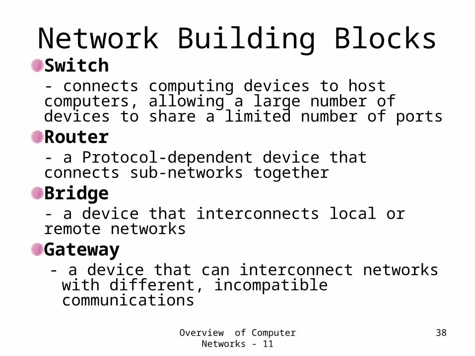
Network Building BlocksSwitch- connects computing devices to host computers, allowing a large number of devices to share a limited number of ports Router- a Protocol-dependent device that connects sub-networks together Bridge- a device that interconnects local or remote networks Gateway- a device that can interconnect networks
with different, incompatible communications

Overview of Computer Networks - 12
39
Network Building Blocks (Continued)Network hosts, workstations, etc.
- they generally represent the source and sink (destination) of data traffic (packets)Multiplexer- telecommunications device that funnels multiple signals onto a single channel Transceiver- (short for transmitter-receiver), is a device that both transmits and receives analog or digital signals. Firewall- a system or group of systems that enforces an access control policy between an organization's network and the Internet for purposes of security.

Overview of Computer Networks - 13
40
“Nuts and bolts” view of the Internet
It is a loosely hierarchical network of networks (some private intranets) with millions of connected computing devices:Hosts, end-systems (Network Edge)– pc’s workstations, servers– PDA (Personal Digital Assistant)’s
phones, toasters
running network apps :Communication links (Network Access)– fiber, coaxial cable, copper, radio,
satellite
Switches, routers, bridges, gateways (Network Core)
local ISP
companynetwork
regional ISP
router workstation
servermobile

Overview of Computer Networks - 14
41
What’s a protocol?Human protocols:
A way of communication between humans
Dictated by local cultureGreeting, response, action takenExamples: “Hey, got time?,” “I have a dumb question,” This is so and so..”
Network protocols: Machines rather than humans involved, but all Internet communication activity is governed by protocolsDictated by standardsProtocols define format, order of messages sent and received among network entities, and actions taken on message transmission and receiptExample: TCP/IP, ISO

Overview of Computer Networks - 15
42
Human and Network Protocol Examples
Hi
Hi
Got thetime?
2:00
TCP connection req.
TCP connectionreply.Get http://www.ee.unt.edu/public/guturu
<file>time

Overview of Computer Networks - 16
43
ProtocolsBuilding blocks of a network architecture
Each protocol object has two different interfaces– service interface: defines operations on this
protocol– peer-to-peer interface: defines messages
exchanged with peer
Term “protocol” is overloaded– specification of peer-to-peer interface– module that implements this interface

Overview of Computer Networks - 17
44
Why Protocol “Layers?”
Networks are complex; they have many heterogeneous “pieces”:– Hosts, routers,
links of various media, Application entities, protocols, hardware, software …
Question: How to achieve
effective communication in
this mess?
Simple Answer: Divide & Conquer

Overview of Computer Networks - 18
45
Why layering?Divide & Conquer Policy to handle Complex
systems:Explicit structure allows identification of complex system’s pieces and their inter-relationships.– Following slides present an example of a layered
real-life protocol. Modularization eases maintenance and updating of system– change of implementation of layer’s service
transparent to rest of system e.g., change in gate procedure doesn’t affect rest of system
Cost: Layering may affect efficiency, but is inevitable.
Overview of Computer Networks - 19
46
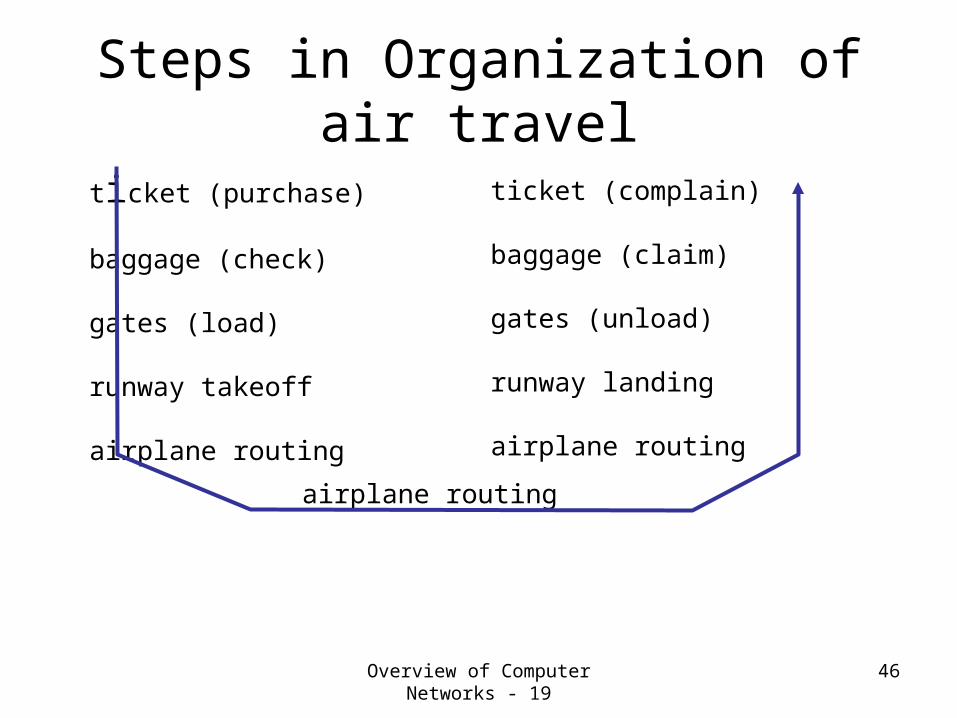
Steps in Organization of air travel
ticket (purchase)
baggage (check)
gates (load)
runway takeoff
airplane routing
ticket (complain)
baggage (claim)
gates (unload)
runway landing
airplane routing
airplane routing

Overview of Computer Networks - 20
47
Layered services in air travel
Counter-to-counter delivery of person+bags
baggage-claim-to-baggage-claim delivery
people transfer: loading gate to arrival gate
runway-to-runway delivery of plane
airplane routing from source to destination
Overview of Computer Networks - 21
48
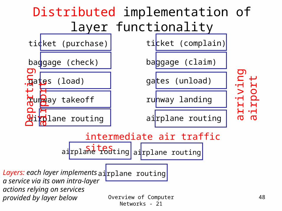
Distributed implementation of layer functionality
ticket (purchase)
baggage (check)
gates (load)
runway takeoff
airplane routing
ticket (complain)
baggage (claim)
gates (unload)
runway landing
airplane routing
airplane routing
Dep
art
ing
air
port
arr
ivin
g
air
port
intermediate air traffic sites
airplane routing airplane routing
Layers: each layer implements a service via its own intra-layer actions relying on services provided by layer below

Overview of Computer Networks - 22
49
Internet protocol stack• Application: supporting network applications (e.g. ftp, smtp,
http)• Transport: host-host data transfer, defines quality and nature of
data delivery (e.g. tcp, udp)application
transport
network
link
physical
•Network: addressing and routing of datagrams from source to destination (e,g. Ip & other routing protocols)•Link: logical organization of data bits transmitted
on a particular medium; framing, addressing, error correction/detection (check sum) e.g. ppp, ethernet
•Physical: bits “on the wire” Defines physical
Properties of various media e.g. Ether-Net cable size
•7-layer OSI protocol (of ISO) has session (reply and response packet pairing) and presentation layers (data syntax, encryption) above transport and below application layer.
Overview of Computer Networks - 23
50
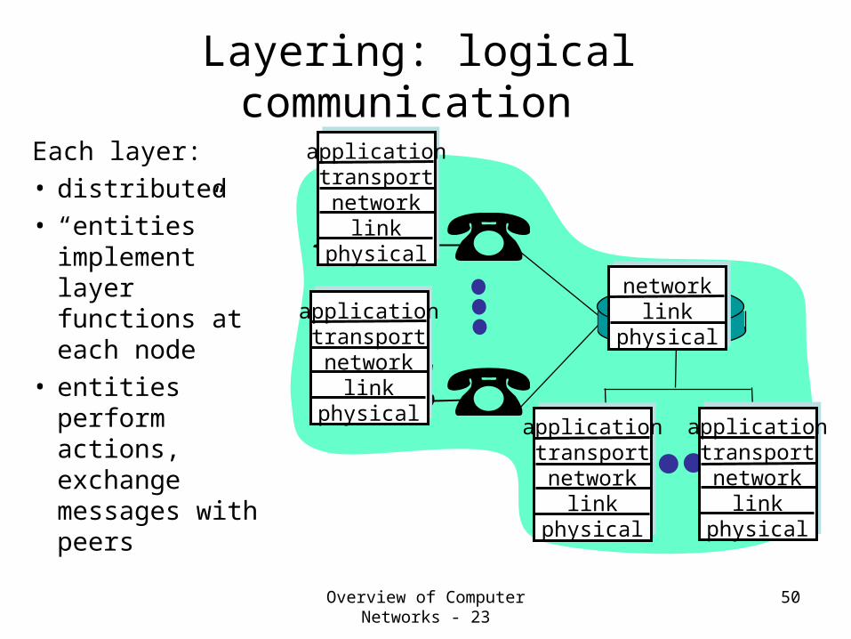
Layering: logical communication
applicationtransportnetwork
linkphysical
applicationtransportnetwork
linkphysical
applicationtransportnetwork
linkphysical
applicationtransportnetwork
linkphysical
networklink
physical
Each layer:• distributed• “entities”
implement layer functions at each node
• entities perform actions, exchange messages with peers
Overview of Computer Networks - 24
51
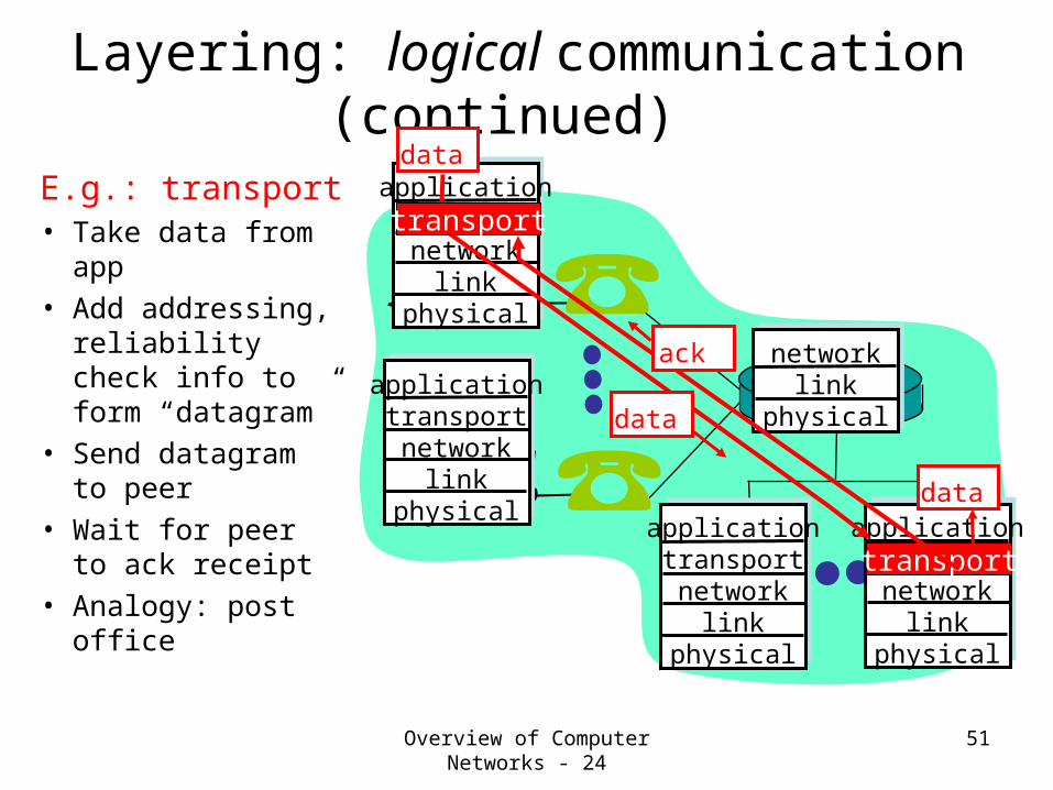
Layering: logical communication (continued)
applicationtransportnetwork
linkphysical
applicationtransportnetwork
linkphysical
applicationtransportnetwork
linkphysical
applicationtransportnetwork
linkphysical
networklink
physical
data
dataE.g.: transport• Take data from
app• Add addressing,
reliability check info to form “datagram”
• Send datagram to peer
• Wait for peer to ack receipt
• Analogy: post office
data
transport
transport
ack

Overview of Computer Networks - 25
52
Layering: physical communication
applicationtransportnetwork
linkphysical
applicationtransportnetwork
linkphysical
applicationtransportnetwork
linkphysical
applicationtransportnetwork
linkphysical
networklink
physical
data
data

Overview of Computer Networks - 26
53
Protocol layering and data Each layer takes data from above, adds header
information to create new data unit and passes new data unit to layer below
applicationtransportnetwork
linkphysical
applicationtransportnetwork
linkphysical
source destination
M
M
M
M
Ht
HtHn
HtHnHl
M
M
M
M
Ht
HtHn
HtHnHl
message
segment
datagram
frame

Overview of Computer Networks - 27
54
Protocol Data Units
The combination of data from the next higher layer and control information is referred to as PDU.
Control Information in the Transport Layer may include:
Destination Service Access Point (DSAP)Sequence numberError-detection code

Overview of Computer Networks - 28
55
Service Access Point
A Service Access Point (SAP) is the location where a layer (N-1) entity provides service for a layer (N) entity.
SDU: Service Data UnitICI: Interface Control InformationIDU: Interface Data UnitPDU: Protocol Data Unit

Overview of Computer Networks -29
56
Summary of the Lesson 2In this lesson, we addressed the question- What is a Computer Network?
We studied the classification of computer networks from different perspectives i.e. had a taxonomic view.We had a components view of the computer network.
We have also studied a little bit of how the interconnected computers communicate with one another, that is, we had cursory glance at protocol layers/stacks.

Lesson 3: Application Layer - 1 57
Lesson 3: Preview/Objectives
High level view of network application protocolsclient server paradigmservice models
learn about protocols by examining popular application-level protocols such as
dnssmtppop ftp (Next Lesson)http (Next Lesson)Multimedia (Next Lesson)

Lesson 3: Application Layer - 2 58
Application layer – Some JargonApplications (e.g., email, file
transfer, the Web): communicating, distributed processes
running in network hosts in “user space”
exchange messages to implement app
Application-layer protocols
one “piece” of an app
define messages exchanged by apps and actions taken
Depend on user services provided by lower layer protocols
application
transportnetworkdata linkphysical
application
transportnetworkdata linkphysical
application
transportnetworkdata linkphysical

Lesson 3: Application Layer - 3 59
Network applications: some jargon
A process is a program that is running within a host.
Within the same host, two processes communicate with inter-process communication defined by the OS.Processes running in different hosts communicate with an application-layer protocol
A user agent is an interface between the user and the network application.
Web-browserE-mail: mail readerstreaming audio/video: media player

Lesson 3: Application Layer - 4 60
Typical Application has two pieces:Client and Server
Client-server paradigm
application
transportnetworkdata linkphysical
application
transportnetworkdata linkphysical
Client:initiates contact with server (“speaks first”)typically requests service from server, for Web, client is implemented in browser; for e-mail, in mail reader
Server:provides requested service to cliente.g., Web server sends requested Web page, mail server delivers e-mail
request
reply

Lesson 3:Application Layer - 5 61
Client-Server Communication
Client and Sever, as a matter of fact, any two applications on different hosts, communicate using what is called an API: application programming interface that
defines interface between application and transport layer e.g. socket: the Internet API
two processes communicate by writing data into socket and reading data out of socket
How does a process “identify” the other process with which it wants to communicate?
IP address of host running other process
“Port number” - allows receiving host to determine to which local process the message should be delivered
Lesson 3:Application Layer - 6 62
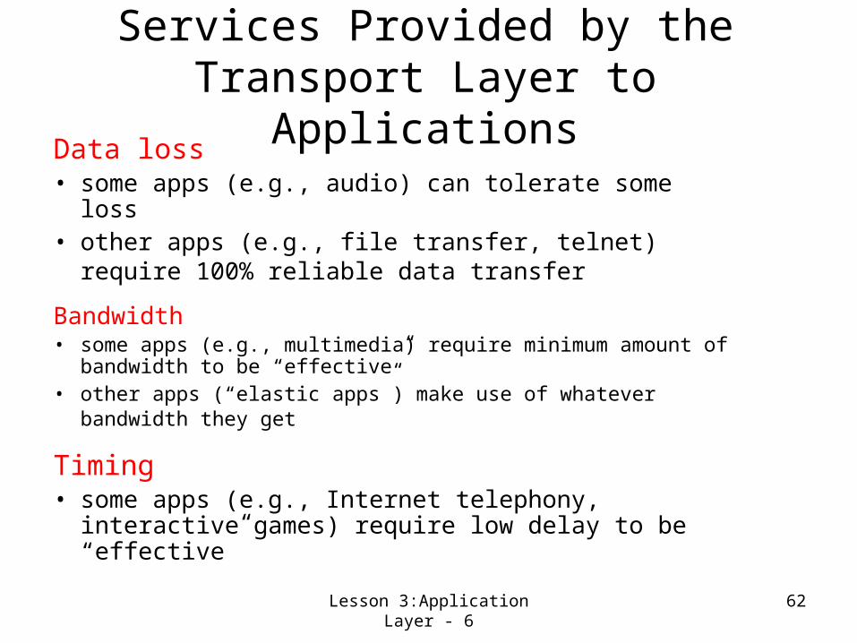
Services Provided by the Transport Layer to Applications
Data loss• some apps (e.g., audio) can tolerate some loss• other apps (e.g., file transfer, telnet) require
100% reliable data transfer
Bandwidth• some apps (e.g., multimedia) require minimum amount
of bandwidth to be “effective”• other apps (“elastic apps”) make use of whatever
bandwidth they get
Timing• some apps (e.g., Internet telephony, interactive
games) require low delay to be “effective”

Lesson 3:Application Layer - 7 63
Transport service requirements of common
appsApplication
file transfere-mail
Web documentsreal-time audio/video
stored audio/videointeractive games
financial apps
Data loss
no lossno lossloss-tolerantloss-tolerant
loss-tolerantloss-tolerantno loss
Bandwidth
elasticelasticelasticaudio: 5Kb-1Mbvideo:10Kb-5Mbsame as above few Kbps upelastic
Time Sensitive
nononoyes, 100’s msec
yes, few secsyes, 100’s msecyes and no

Lesson 3:Application Layer - 8 64
Services provided by Internet transport protocols
TCP service:• connection-oriented: setup
required between client, server
• reliable transport between sending and receiving process
• flow control: sender won’t overwhelm receiver
• congestion control: throttle sender when network overloaded
• does not provide: timing, minimum bandwidth guarantees
UDP service:• unreliable data
transfer between sending and receiving process
• does not provide: connection setup, reliability, flow control, congestion control, timing, or bandwidth guarantee
Q: why bother? Why is there a UDP?
Lesson 3:Application Layer - 9 65
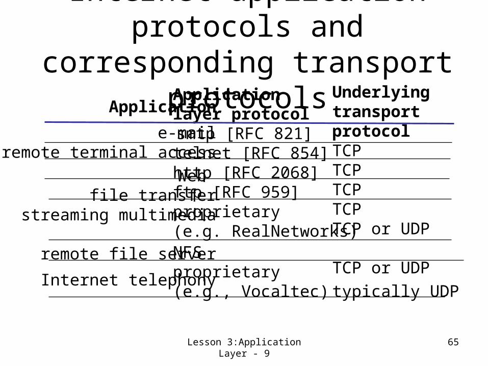
Internet application protocols and corresponding
transport protocolsApplication
e-mailremote terminal access
Web file transfer
streaming multimedia
remote file server
Internet telephony
Applicationlayer protocol smtp [RFC 821]telnet [RFC 854]http [RFC 2068]ftp [RFC 959]proprietary(e.g. RealNetworks)NFSproprietary(e.g., Vocaltec)
Underlyingtransport protocolTCPTCPTCPTCPTCP or UDP
TCP or UDPtypically UDP
Lesson 3: Application Layer - 10 66
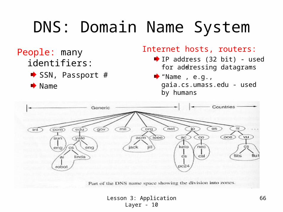
DNS: Domain Name System
People: many identifiers:SSN, Passport #Name
Internet hosts, routers:IP address (32 bit) - used for addressing datagrams“Name”, e.g., gaia.cs.umass.edu - used by humans

Lesson 3: Application Layer - 11 67
DNS: Domain Name SystemApplication providing Mapping between IP addresses and domain namedistributed database implemented in hierarchy of many name serversapplication-layer protocol host, routers, name servers to communicate to resolve names (address/name translation)
note: core Internet function implemented as application-layer protocolcomplexity at network’s “edge”

Lesson 3: Application Layer - 12 68
DNS name servers
Two types Name servers-Local name servers:
each ISP, company has local (default) name serverhost DNS query first goes to local name server
Authoritative name server:for a host: stores that host’s IP address, namecan perform name/address translation for that host’s name
Why not centralize DNS?single point of failuretraffic volumedistant centralized databaseMaintenancedoesn’t scale!
Hence, the distributed organization where server has all name-to-IP address mappings.
Lesson 3: Application Layer - 13 69
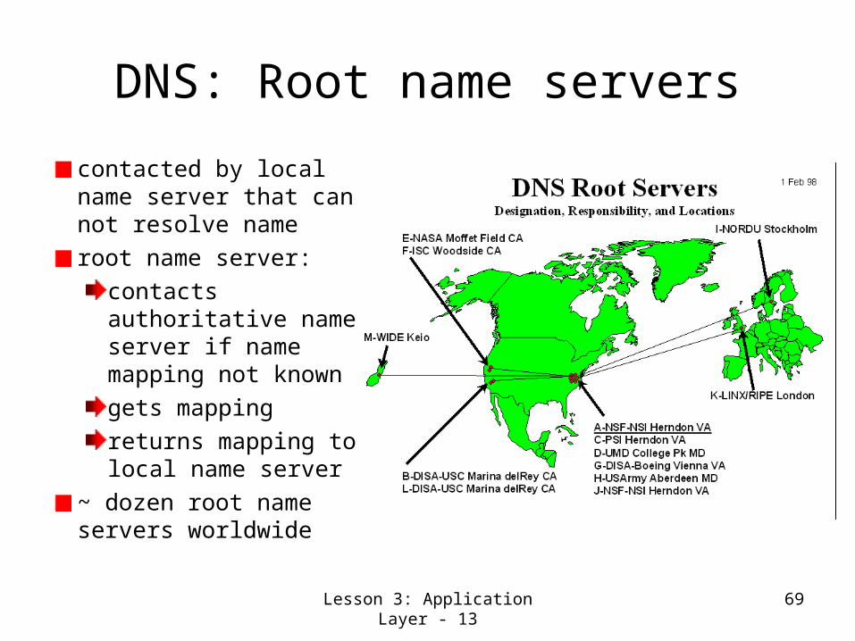
DNS: Root name servers
contacted by local name server that can not resolve nameroot name server:
contacts authoritative name server if name mapping not knowngets mappingreturns mapping to local name server
~ dozen root name servers worldwide

Lesson 3: Application Layer - 14 70
Simple DNS ScenarioHost surf.eurecom.fr
wants IP address of gaia.cs.umass.edu
1. Contacts its local DNS server, dns.eurecom.fr
2. dns.eurecom.fr contacts root name server, if necessary
3. root name server contacts authoritative name server, dns.umass.edu, if necessary
4, 5 & 6 are responses in reverse order.
requesting hostsurf.eurecom.fr
gaia.cs.umass.edu
root name server
authorititive name serverdns.umass.edu
local name serverdns.eurecom.fr
1
23
45
6

Lesson 3: Application Layer - 15 71
A More Complex DNS Scenario
Root name server:may not know authoratiative name server, butmay know intermediate name server: who to contact to find authoritative name server
requesting hostsurf.eurecom.fr
gaia.cs.umass.edu
root name server
local name serverdns.eurecom.fr
1
23
4 5
6
authoritative name serverdns.cs.umass.edu
intermediate name serverdns.umass.edu
7
8
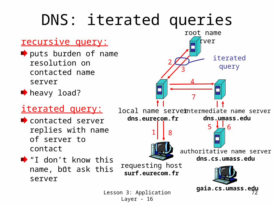
Lesson 3: Application Layer - 16 72
DNS: iterated queriesrecursive query:
puts burden of name resolution on contacted name serverheavy load?
iterated query:contacted server replies with name of server to contact“I don’t know this name, but ask this server”
requesting hostsurf.eurecom.fr
gaia.cs.umass.edu
root name server
local name serverdns.eurecom.fr
1
23
4
5 6
authoritative name serverdns.cs.umass.edu
intermediate name serverdns.umass.edu
7
8
iterated query

Lesson 3: Application Layer - 17 73
DNS: caching and updating records
once (any) name server learns mapping, it caches mapping– cache entries timeout (disappear) after
some time
update/notify mechanisms under design by IETF
RFC 2136http://www.ietf.org/html.charters/dnsind-charter.html

Lesson 3: Application Layer - 18 74
DNS recordsDNS: distributed db storing resource records (RR)
Type=NSname is domain (e.g. foo.com)value is IP address of authoritative name server for this domain
RR format: (name, value, type,ttl)
Type=Aname is hostnamevalue is IP address
Type=CNAMEname is an alias name for some “cannonical” (the real) namevalue is cannonical nameType=MXvalue is hostname of mail server associated with name

Lesson 3: Application Layer - 19 75
DNS protocol & messagesDNS protocol : query and repy messages, both with same message format
msg header• identification: 16 bit
# for query, repy to query uses same #
• flags:– query or reply– recursion desired – recursion
available– reply is
authoritative

Lesson 3: Application Layer - 20 76
DNS protocol & messages (Continued)
Name, type fields for a query
RRs in reponseto query
records forauthoritative servers
additional “helpful”info that may be used
Lesson 3: Application Layer - 21 77
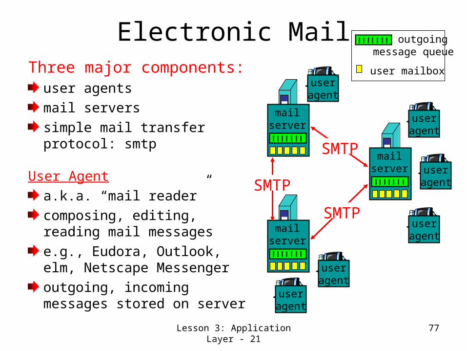
Electronic MailThree major components:
user agents mail servers simple mail transfer protocol: smtp
User Agenta.k.a. “mail reader”composing, editing, reading mail messagese.g., Eudora, Outlook, elm, Netscape Messengeroutgoing, incoming messages stored on server
user mailbox
outgoing message queue
mailserver
useragent
useragent
useragent
mailserver
useragent
useragent
mailserver
useragent
SMTP
SMTP
SMTP

Lesson 3: Application Layer - 22 78
Electronic Mail: mail servers
Mail Servers mailbox contains incoming messages (yet to be read) for usermessage queue of outgoing (to be sent) mail messagessmtp protocol between mail servers to send email messages
client: sending mail server“server”: receiving mail server
mailserver
useragent
useragent
useragent
mailserver
useragent
useragent
mailserver
useragent
SMTP
SMTP
SMTP

Lesson 3: Application Layer - 23 79
Electronic Mail: smtp [RFC 821]uses tcp to reliably transfer email msg from client to server, port 25
direct transfer: sending server to receiving server
three phases of transfer
handshaking (greeting)
transfer of messages
closure
command/response interaction
commands: ASCII text
response: status code and phrase
messages must be in 7-bit ASCII

Lesson 3: Application Layer - 24 80
Try smtp interaction for yourself
• telnet servername 25• see 220 reply from server
• enter HELO, MAIL FROM, RCPT TO, DATA, QUIT commands
above lets you send email without using email client (reader)
Lesson 3: Application Layer - 25 81
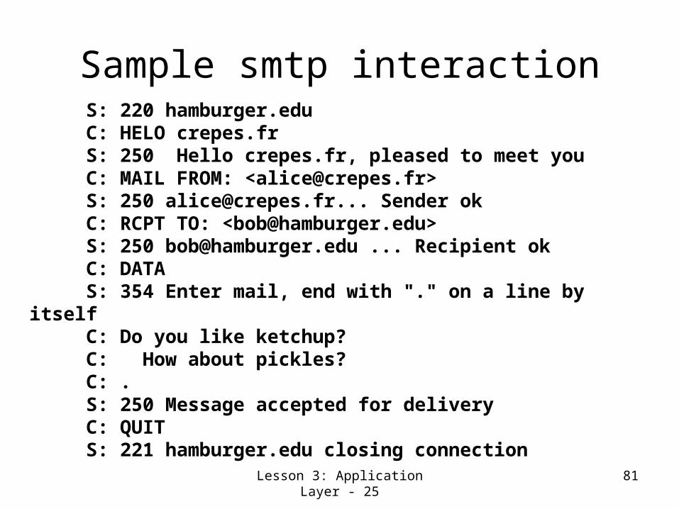
Sample smtp interaction S: 220 hamburger.edu C: HELO crepes.fr S: 250 Hello crepes.fr, pleased to meet you C: MAIL FROM: <[email protected]> S: 250 [email protected]... Sender ok C: RCPT TO: <[email protected]> S: 250 [email protected] ... Recipient ok C: DATA S: 354 Enter mail, end with "." on a line by itself C: Do you like ketchup? C: How about pickles? C: . S: 250 Message accepted for delivery C: QUIT S: 221 hamburger.edu closing connection

Lesson 3: Application Layer - 26 82
smtp: Some Observations
• smtp uses persistent connections
• smtp requires that message (header & body) be in 7-bit ascii
• certain character strings are not permitted in message (e.g., CRLF.CRLF). Thus message has to be encoded (usually into either base-64 or quoted printable)
• smtp server uses CRLF.CRLF to determine end of message
Comparison with http
• http: pull• email: push
• both have ASCII command/response interaction, status codes
• http: each object is encapsulated in its own response message
• smtp: multiple objects message sent in a multipart message

Lesson 3: Application Layer - 27 83
Mail message format
smtp: protocol for exchanging email msgs
RFC 822: standard for text message format:
• header lines, e.g.,– To:– From:– Subject:different from smtp
commands!
• body– the “message”, ASCII
characters only
header
body
blankline
Lesson 3: Application Layer - 28 84
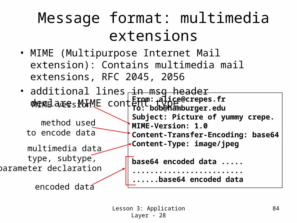
Message format: multimedia extensions
• MIME (Multipurpose Internet Mail extension): Contains multimedia mail extensions, RFC 2045, 2056
• additional lines in msg header declare MIME content type From: [email protected]
To: [email protected] Subject: Picture of yummy crepe. MIME-Version: 1.0 Content-Transfer-Encoding: base64 Content-Type: image/jpeg
base64 encoded data ..... ......................... ......base64 encoded data
multimedia datatype, subtype,
parameter declaration
method usedto encode data
MIME version
encoded data

Lesson 3: Application Layer - 29 85
MIME typesContent-Type: type/subtype;
parametersText
example subtypes: plain, html
Imageexample subtypes: jpeg, gif
Audioexampe subtypes: basic (8-bit mu-law encoded), 32kadpcm (32 kbps coding)
Videoexample subtypes: mpeg, quicktime
Applicationother data that must be processed by reader before “viewable”example subtypes: msword, octet-stream

Lesson 3: Application Layer - 30 86
Multipart TypeFrom: [email protected] To: [email protected] Subject: Picture of yummy crepe. MIME-Version: 1.0 Content-Type: multipart/mixed; boundary=98766789 --98766789Content-Transfer-Encoding: quoted-printableContent-Type: text/plain
Dear Bob, Please find a picture of a crepe.--98766789Content-Transfer-Encoding: base64Content-Type: image/jpeg
base64 encoded data ..... ......................... ......base64 encoded data --98766789--

Lesson 3: Application Layer - 31 87
Mail access protocols
• SMTP: delivery/storage to receiver’s server• Mail access protocol: retrieval from server
– POP3: Post Office Protocol version 3 [RFC 1939]• authorization (agent <-->server) and download
– IMAP: Internet Mail Access Protocol [RFC 2060]• more features (more complex)• manipulation of stored msgs on server
– Webmail/HTTP: Hotmail , Yahoo! Mail, etc.
useragent
sender’s mail server
useragent
SMTP SMTP POP3 orIMAP
receiver’s mail server

Lesson 3: Application Layer - 32 88
POP3 protocolauthorization phase• client commands:
– user: declare username– pass: password
• server responses– +OK– -ERR
transaction phase, client:• list: list message numbers• retr: retrieve message by
number• dele: delete• quit
C: list S: 1 498 S: 2 912 S: . C: retr 1 S: <message 1 contents> S: . C: dele 1 C: retr 2 S: <message 1 contents> S: . C: dele 2 C: quit S: +OK POP3 server signing off
S: +OK POP3 server ready C: user alice S: +OK C: pass hungry S: +OK user successfully logged on

Lesson 3: Application Layer - 33 89
How POP3 Works?
Note : DNS name or IP address of ISP server is typically configured when email is set up.

Lesson 3: Application Layer - 34 90
POP3 versus IMAPPOP3 is widely used because of simplicity and robustness.Both allow downloads from different places, but POP3 assumes user will clear out all messages from server on every contact and works offline after that. This makes email spread on different machines.IMAP (Internet Message Access Protocol) assumes messages remain indefinitely on the server.IMAP provides facilities to manipulate messages/ mailboxes on the server

Lesson 3: Application Layer - 35 91
Lesson 3: Summary and Follow-up
We had a High level view of network application protocols using
client server paradigmservice models
We learned about three of the most common application-level protocols
dnssmtppop
In the next class, we deal with three very popular application protocols
ftp httpMultimedia
92
Lesson 4: More Application Layer
Protocols

Lesson 4: More Application Layer Protocols - 1
93
Lesson 4: Preview/Objectives
Learn about the following popular application-level protocols
ftp http Multimedia
Lesson 4: More Application Layer Protocols - 2
94
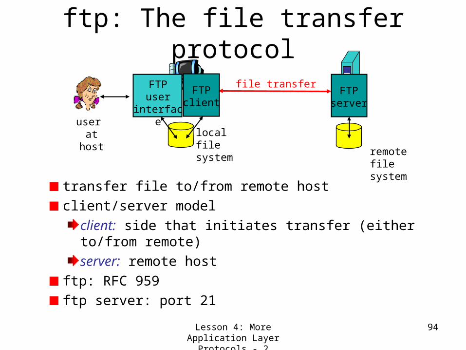
ftp: The file transfer protocol
transfer file to/from remote hostclient/server model
client: side that initiates transfer (either to/from remote)server: remote host
ftp: RFC 959ftp server: port 21
file transferFTP
server
FTPuser
interface
FTPclient
local filesystem
remote filesystem
user at host
Lesson 4: More Application Layer Protocols - 3
95
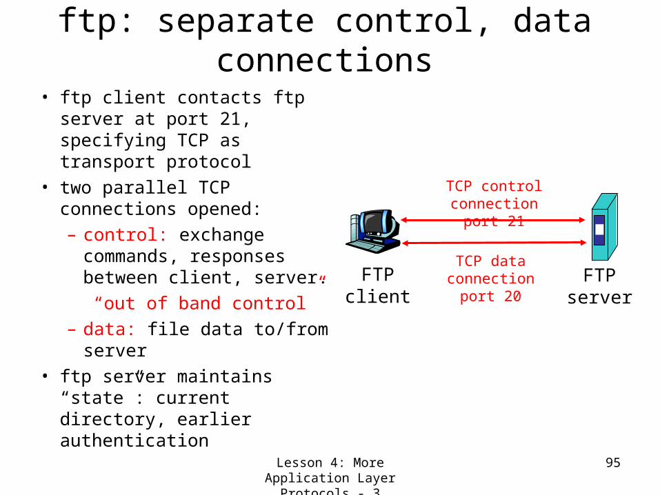
ftp: separate control, data connections
• ftp client contacts ftp server at port 21, specifying TCP as transport protocol
• two parallel TCP connections opened:– control: exchange
commands, responses between client, server.“out of band control”
– data: file data to/from server
• ftp server maintains “state”: current directory, earlier authentication
FTPclient
FTPserver
TCP control connection
port 21
TCP data connectionport 20

Lesson 4: More Application Layer Protocols - 4
96
ftp commands, responsesSample commands:• sent as ASCII text over
control channel• USER username• PASS password• dir/ls return list of files
in current directory
• Put filename retrieves (gets) file
• Get filename stores (puts) a local file on remote host
Sample return codes• status code and phrase
(as in http)• 331 Username OK,
password required• 125 data connection
already open; transfer starting
• 425 Can’t open data connection
• 452 Error writing file

Lesson 4: More Application Layer Protocols - 5
97
The Web: some jargonWeb page
consists of “objects”addressed by a URL
Most Web pages consist of:
base HTML page, andseveral referenced objects.
URL has three components: protocol, host name and path name:
User agent for Web is called a browser:
MS Internet ExplorerNetscape Communicator
Server for Web is called Web server:
Apache (public domain)MS Internet Information Server
http://www.someSchool.edu/someDept/pic.gif

Lesson 4: More Application Layer Protocols - 6
98
The Web: the http protocolhttp: hypertext transfer
protocolWeb’s application layer protocolclient/server model
client: browser that requests, receives, “displays” Web objectsserver: Web server sends objects in response to requests
http1.0: RFC 1945http1.1: RFC 2068
PC runningExplorer
Server running
NCSA Webserver
Mac runningNavigator
http request
http re
quest
http response
http re
sponse
The Internet
DNS Server Ip request
Ip response

Lesson 4: More Application Layer Protocols - 7
99
Navigation through The WebMultiple servers may come into playThe same client/server model
client: browser that requests, receives, “displays” Web objectsserver: Web server sends objects in response to requests
Browser determines URL and asks DNS for IP addressBrowser makes TCP connection on port 80
PC runningExplore
r
abc.com Webserver
http request ( following
hyperlink to abc.com)
htt
p r
equest
http response with a
page having hyperlink to XYZ.com
htt
p r
esp
onse
The Internet
XYZ.com Webserver
DNS Server Ip request
Ip response
Lesson 4: More Application Layer Protocols - 8
100
More about the http protocol
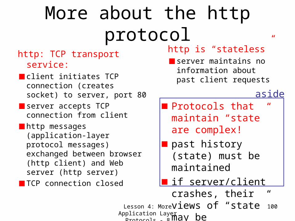
http: TCP transport service:client initiates TCP connection (creates socket) to server, port 80server accepts TCP connection from clienthttp messages (application-layer protocol messages) exchanged between browser (http client) and Web server (http server)TCP connection closed
http is “stateless”server maintains no information about past client requests
Protocols that maintain “state” are complex!past history (state) must be maintainedif server/client crashes, their views of “state” may be inconsistent, must be reconciled
aside
Lesson 4: More Application Layer Protocols - 9
101
Further Details for the http example
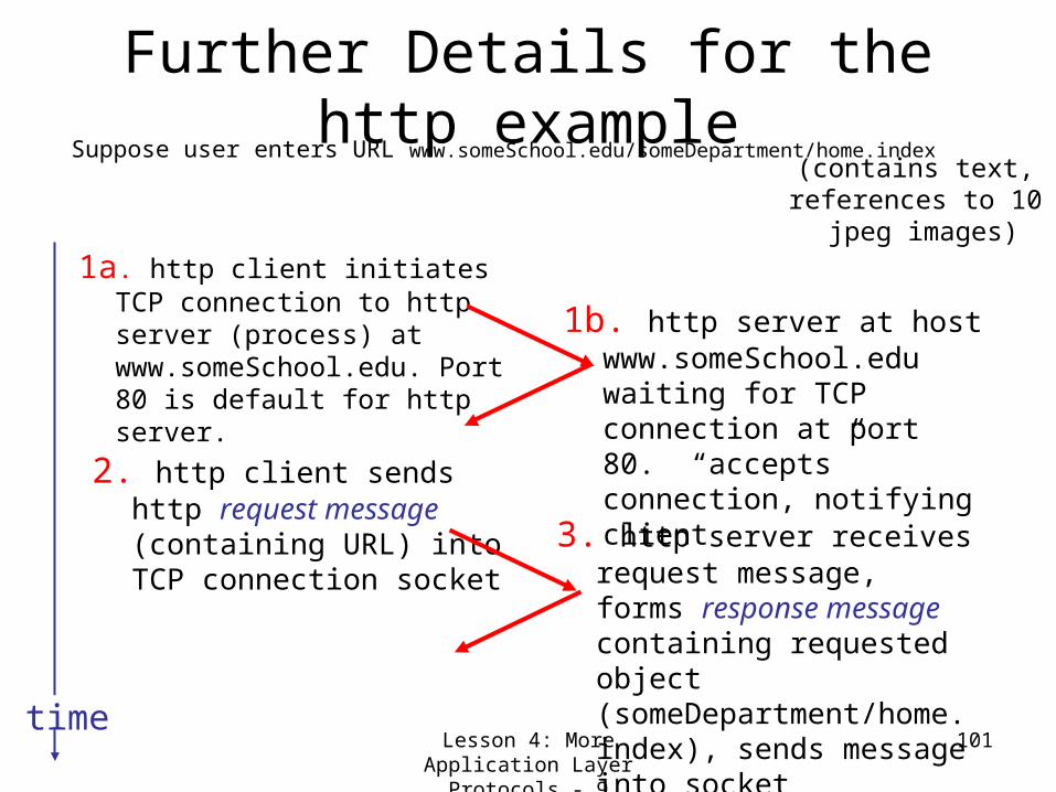
Suppose user enters URL www.someSchool.edu/someDepartment/home.index
1a. http client initiates TCP connection to http server (process) at www.someSchool.edu. Port 80 is default for http server.
2. http client sends http request message (containing URL) into TCP connection socket
1b. http server at host www.someSchool.edu waiting for TCP connection at port 80. “accepts” connection, notifying client
3. http server receives request message, forms response message containing requested object (someDepartment/home.index), sends message into socket
time
(contains text, references to 10
jpeg images)

Lesson 4: More Application Layer Protocols - 10
102
http example (cont.)
5. http client receives response message containing html file, displays html. Parsing html file, finds 10 referenced jpeg objects
6. Steps 1-5 repeated for each of 10 jpeg objects
4. http server closes TCP connection.
time

Lesson 4: More Application Layer Protocols - 11
103
Non-persistent and persistent connections
Non-persistentHTTP/1.0server parses request, responds, and closes TCP connection2 Request-response messages to fetch each objectEach object transfer suffers from slow start
Persistentdefault for HTTP/1.1on same TCP connection: server parses request, responds, parses new request,..Client sends requests for all referenced objects as soon as it receives base HTML.Fewer Request-response messages and less slow start.
But most 1.0 browsers useparallel TCP connections.
Lesson 4: More Application Layer Protocols - 12
104
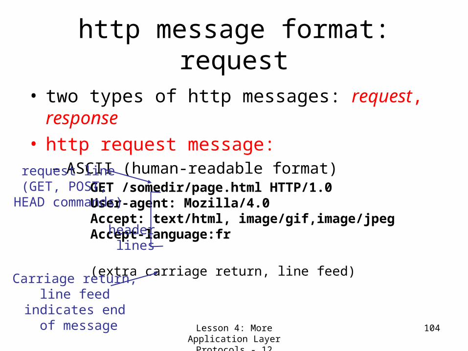
http message format: request
• two types of http messages: request, response
• http request message:– ASCII (human-readable format)
GET /somedir/page.html HTTP/1.0 User-agent: Mozilla/4.0 Accept: text/html, image/gif,image/jpeg Accept-language:fr
(extra carriage return, line feed)
request line(GET, POST,
HEAD commands)
header lines
Carriage return, line feed
indicates end of message

Lesson 4: More Application Layer Protocols - 13
105
http request message: general format

http Request Example
106Lesson 4: More Application Layer Protocols – 13.1

Lesson 4: More Application Layer Protocols - 14
107
http message format: response
HTTP/1.0 200 OK Date: Thu, 06 Aug 1998 12:00:15 GMT Server: Apache/1.3.0 (Unix) Last-Modified: Mon, 22 Jun 1998 …... Content-Length: 6821 Content-Type: text/html data data data data data ...
status line(protocol
status codestatus phrase)
header lines
data, e.g., requestedhtml file

http Response Example
108
Lesson 4: More Application Layer Protocols – 14.1

Lesson 4: More Application Layer Protocols - 15
109
http response status codes
200 OK– request succeeded, requested object later in this
message
301 Moved Permanently– requested object moved, new location specified
later in this message (Location:)
400 Bad Request– request message not understood by server
404 Not Found– requested document not found on this server
505 HTTP Version Not Supported
In first line in server->client response message.
A few sample codes:

Lesson 4: More Application Layer Protocols - 16
110
Trying out http (client side) for yourself
1. Telnet to your favorite Web server:
Opens TCP connection to port 80(default http server port) at www.eurecom.fr.Anything typed in sent to port 80 at www.eurecom.fr
telnet www.eurecom.fr 80
2. Type in a GET http request:GET /~ross/index.html HTTP/1.0 By typing this in (hit carriage
return twice), you sendthis minimal (but complete) GET request to http server
3. Look at response message sent by http server!

Lesson 4: More Application Layer Protocols - 17
111
User-server interaction: authenticationAuthentication goal: control
access to server documentsstateless: client must present authorization in each requestauthorization: typically name, password
authorization: header line in requestif no authorization presented, server refuses access, sends
WWW authenticate:
header line in response
client server
usual http request msg401: authorization req.
WWW authenticate:
usual http request msg
+ Authorization:lineusual http response
msg
usual http request msg
+ Authorization:lineusual http response
msgtime
Browser caches name & password sothat user does not have to repeatedly enter it.
Lesson 4: More Application Layer Protocols - 18
112
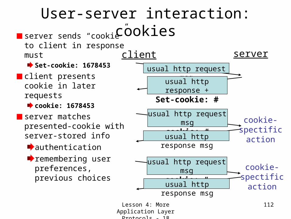
User-server interaction: cookiesserver sends “cookie” to client in response must
Set-cookie: 1678453
client presents cookie in later requests
cookie: 1678453
server matches presented-cookie with server-stored info
authenticationremembering user preferences, previous choices
client server
usual http request msgusual http response
+Set-cookie: #
usual http request msg
cookie: #usual http response
msg
usual http request msg
cookie: #usual http response msg
cookie-spectificaction
cookie-spectificaction

Lesson 4: More Application Layer Protocols - 19
113
User-server interaction: conditional GET
• Goal: don’t send object if client has up-to-date stored (cached) version
• client: specify date of cached copy in http requestIf-modified-since:
<date>
• server: response contains no object if cached copy up-to-date: HTTP/1.0 304 Not Modified
client server
http request msgIf-modified-since:
<date>
http responseHTTP/1.0
304 Not Modified
object not
modified
http request msgIf-modified-since:
<date>
http responseHTTP/1.1 200 OK
…
<data>
object modified

Lesson 4: More Application Layer Protocols - 20
114
Web Caches (proxy server)
user sets browser: Web accesses via web cache
client sends all http requests to web cache
if object at web cache, web cache immediately returns object in http response else requests object from origin server, then returns http response to client
Goal: satisfy client request without involving origin server
client
Proxyserver
client
http request
http re
quest
http response
http re
sponse
http re
quest
http re
sponse
http requesthttp response
origin server
origin server

Lesson 4: More Application Layer Protocols - 21
115
Why Web Caching?
Assume: cache is “close” to client (e.g., in same network)
• smaller response time: cache “closer” to client
• decrease traffic to distant servers– link out of
institutional/local ISP network often bottleneck
originservers
public Internet
institutionalnetwork 10 Mbps LAN
1.5 Mbps access link
institutionalcache

Lesson 4: More Application Layer Protocols - 22
116
Streaming Audio (Music on Demand)Some cases web-sever provides link to audio server. Media
player gets the file using Real-time Streaming Protocol (RTSP).

Lesson 4: More Application Layer Protocols - 23
117
Media PlayerFunctions1. User Interface Management 2. Transmission error handling 3. Decompression of music 4. Elimination of jitter.

Lesson 4: More Application Layer Protocols -24
118
Media Player Function: Elimination of Jitter
Concept of push and pull media servers

Lesson 4: More Application Layer Protocols - 25
119
Internet Radio
Lesson 4: More Application Layer Protocols - 26
120
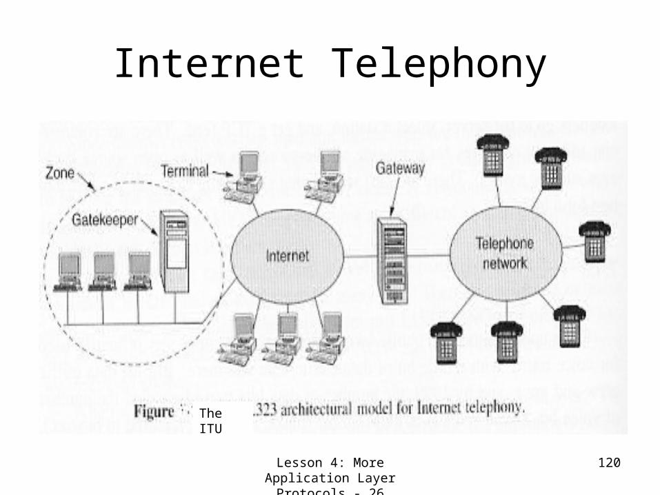
Internet Telephony
The ITU

Lesson 4: More Application Layer Protocols - 27
121
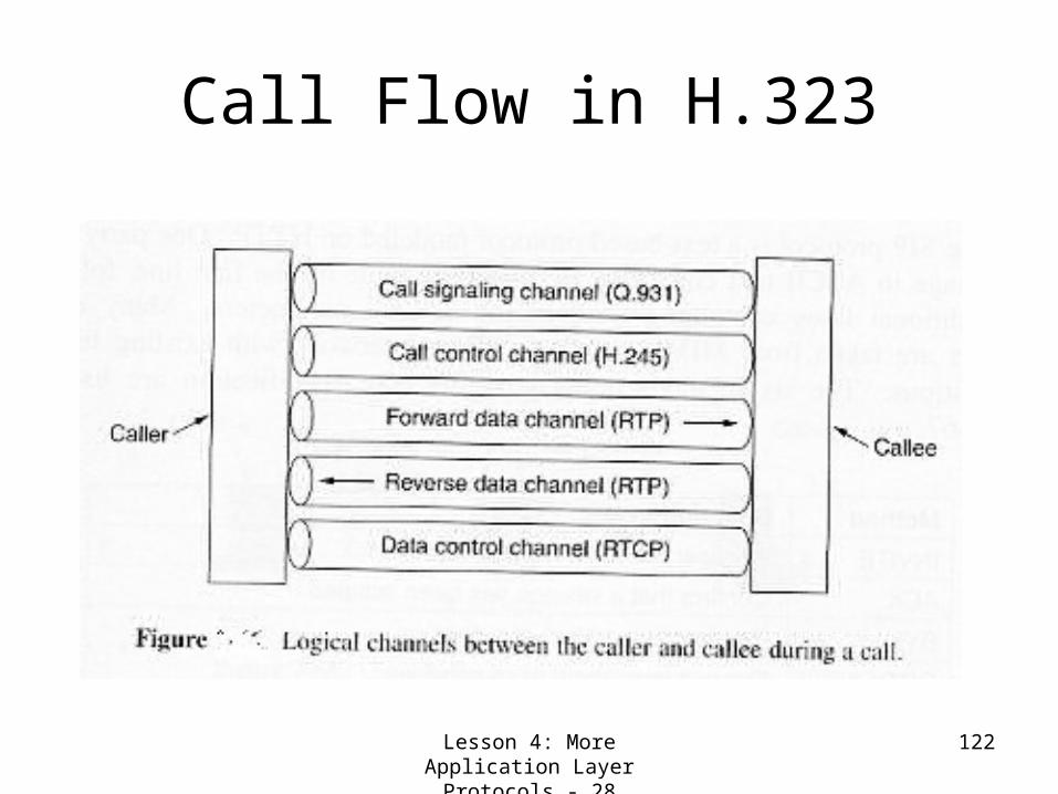
H.323 Protocol StackRTP- Real-time Transport Protocol, RTCP- Real-time Transport Control Protocol, RAS- Registration/Admission/Status. H.245 channel is used to negotiate call parameters such as support for video or conference calls, Codecs supported, and so on.
Used for Congestion control
Allows terminals join and leave zones , request and return bandwidths and provide status updates.
G.711,
G.723.1,
etc.
Lesson 4: More Application Layer Protocols - 28
122
Call Flow in H.323
Lesson 4: More Application Layer Protocols -29
123
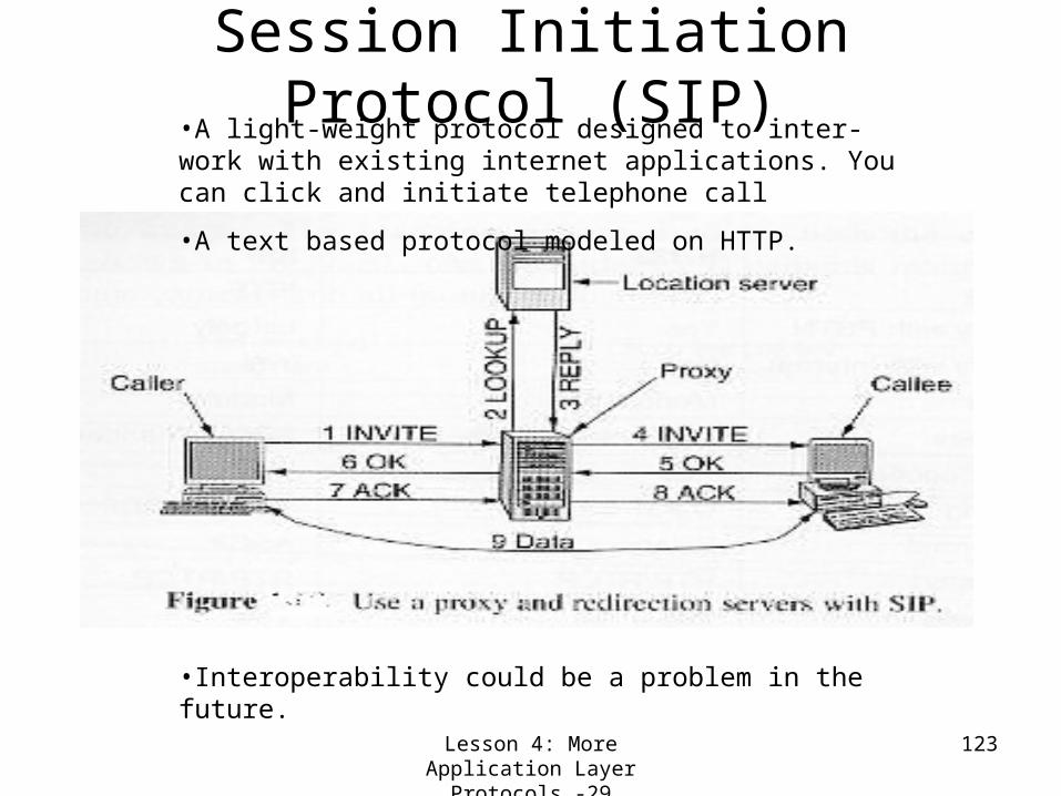
Session Initiation Protocol (SIP)•A light-weight protocol designed to inter-work with existing internet applications. You can click and initiate telephone call
•A text based protocol modeled on HTTP.
•Interoperability could be a problem in the future.

Lesson 4: More Application Layer Protocols - 30
124
Video- Still and Moving Images
MPEG-1 output consists of 4 kinds of frames;
• I (Intra-coded) frames: Self-contained JPEG-encoded still pictures
•P (Predictive) frames: Block-by-block difference with last frame
•B (Bidirectional) frames: Differences between last and next frames
•D (DC-coded): Block averages used for last forward.

Lesson 4: More Application Layer Protocols - 31
125
Video on DemandHere MPEG-2 is more applicable. It is similar to MPEG-1, but uses 10x10 blocks on place of 8x8. It also supports both progressive and interlaced images.

Lesson 4: More Application Layer Protocols - 32
126
Video-servers
TapeDVD
Magnetic Disk
RAM
Zipf’s Law: Most popular movie is seven times as popular as the 7th popular movie. kth popular movie will have C/k of total requests where C= ?

Lesson 4: More Application Layer Protocols -33
127
Lesson 4: Summary and Follow-up
Revisiting the client-server paradigm, we dealt with three very popular application protocols
ftp httpMultimedia
Audio-serversH.323SIPVideo-on-Demand
Next we will take up how to program applications using transport layer services (i.e. TCP/UDP sockets)

128
Lesson 5: Writing Applications using Transport Layer
Facilities

Lesson 5: Writing Applications using Transport Layer Facilities-1
129
Lesson 5: Preview/Objectives
Learn about the usage of the following transport layer facilities for writing client-server applications
UDP socketsTCP sockets
Learn the difference between connection-oriented and connectionless transport layer services.
Lesson 5: Writing Applications using Transport Layer Facilities-2
130
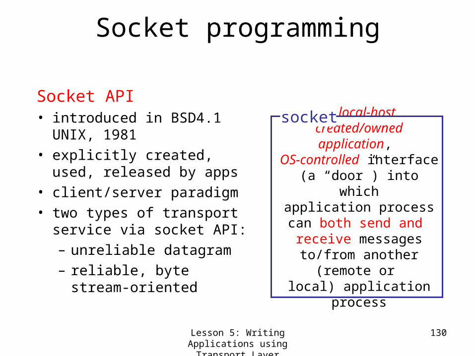
Socket programming
Socket API• introduced in BSD4.1
UNIX, 1981• explicitly created, used,
released by apps • client/server paradigm • two types of transport
service via socket API: – unreliable datagram – reliable, byte stream-
oriented
a local-host created/owned
application, OS-controlled interface (a “door”) into which
application process can both send and
receive messages to/from another (remote
or local) application
process
socket

Lesson 5: Writing Applications using Transport Layer Facilities-3
131
Socket-programming using TCPSocket: a door between application process and
end-end-transport protocol (UDP or TCP)TCP service: reliable transfer of bytes from one
process to another
process
TCP withbuffers,
variables
socket
controlled byapplicationdeveloper
controlled byoperating
system
host orserver
process
TCP withbuffers,
variables
socket
controlled byapplicationdeveloper
controlled byoperatingsystem
host orserver
internet

Lesson 5: Writing Applications using Transport Layer Facilities-4
132
Socket programming with TCPClient must contact server• server process must first
be running• server must have
created socket (door) that welcomes client’s contact
Client contacts server by:• creating client-local TCP
socket• specifying IP address,
port number of server process
• When client creates socket: client TCP establishes connection to server TCP
• When contacted by client, server TCP creates new socket for server process to communicate with client– allows server to talk with
multiple clients
TCP provides reliable, in-order transfer of bytes (“pipe”) between client and server
application viewpoint
Lesson 5: Writing Applications using Transport Layer Facilities-5
133
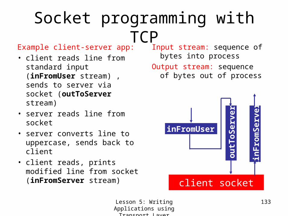
Socket programming with TCPExample client-server app:• client reads line from
standard input (inFromUser stream) , sends to server via socket (outToServer stream)
• server reads line from socket
• server converts line to uppercase, sends back to client
• client reads, prints modified line from socket (inFromServer stream)
Input stream: sequence of bytes into process
Output stream: sequence of bytes out of process
client socket
inFromUser
ou
tToS
erv
er
iin
Fro
mS
er v
er

Lesson 5: Writing Applications using Transport Layer Facilities-6
134
Client/server socket interaction: TCP
wait for incomingconnection request
Socket connectionSocket =welcomeSocket.accept()
create socket,port=x, forincoming request:
welcomeSocket =
ServerSocket()
create socket,connect to hostid, port=x
clientSocket = Socket()
connectionSocket.close()
read reply fromclientSocket
clientSocket.close()
Server (running on hostid) Client
send request usingclientSocketread request from
connectionSocket
write reply toconnectionSocket
TCP connection setup
Unix 4.1c BSD: socket()
connect()
Unix 4.1c BSD: socket() bind() listen() accept()
InputStream Socket.getInputStream() OutputStream Socket.getOutputStream()

Lesson 5: Writing Applications using Transport Layer Facilities-7
135
Example: Java TCP clientimport java.io.*; import java.net.*; class TCPClient {
public static void main(String argv[]) throws Exception { String sentence; String modifiedSentence;
BufferedReader inFromUser = new BufferedReader(new InputStreamReader(System.in));
Socket clientSocket = new Socket("hostname", 6789);
DataOutputStream outToServer = new DataOutputStream(clientSocket.getOutputStream());
Createinput stream
Create client socket,
connect to server
Createoutput stream
attached to socket

Lesson 5: Writing Applications using Transport Layer Facilities-8
136
Example: Java TCP client (cont.)
BufferedReader inFromServer = new BufferedReader(new InputStreamReader(clientSocket.getInputStream()));
sentence = inFromUser.readLine();
outToServer.writeBytes(sentence + '\n');
modifiedSentence = inFromServer.readLine();
System.out.println("FROM SERVER: " + modifiedSentence);
clientSocket.close(); } }
Createinput stream
attached to socket
Send lineto server
Read linefrom server
Lesson 5: Writing Applications using Transport Layer Facilities-9
137
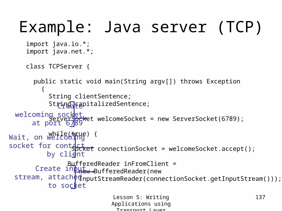
Example: Java server (TCP)import java.io.*; import java.net.*;
class TCPServer {
public static void main(String argv[]) throws Exception { String clientSentence; String capitalizedSentence;
ServerSocket welcomeSocket = new ServerSocket(6789); while(true) { Socket connectionSocket = welcomeSocket.accept();
BufferedReader inFromClient = new BufferedReader(new InputStreamReader(connectionSocket.getInputStream()));
Createwelcoming socket
at port 6789
Wait, on welcomingsocket for contact
by client
Create inputstream, attached
to socket

Lesson 5: Writing Applications on Transport Layer Facilities-10
138
Example: Java TCP server (cont.)
DataOutputStream outToClient = new DataOutputStream(connectionSocket.getOutputStream());
clientSentence = inFromClient.readLine();
capitalizedSentence = clientSentence.toUpperCase() + '\n';
outToClient.writeBytes(capitalizedSentence); } } }
Read in linefrom socket
Create outputstream,
attached to socket
Write out lineto socket
End of while loop,loop back and wait foranother client connection
Lesson 5: Writing Applications on Transport Layer Facilities-11
139
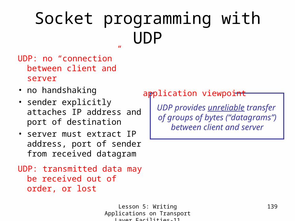
Socket programming with UDP
UDP: no “connection” between client and server
• no handshaking• sender explicitly attaches
IP address and port of destination
• server must extract IP address, port of sender from received datagram
UDP: transmitted data may be received out of order, or lost
application viewpoint
UDP provides unreliable transfer of groups of bytes (“datagrams”)
between client and server

Lesson 5: Writing Applications on Transport Layer Facilities-12
140
Client/Server socket interaction: UDP
closeclientSocket
Server (running on hostid)
read reply fromclientSocket
create socket,clientSocket = DatagramSocket()
Client
Create, address (hostid, port=x,send datagram request using clientSocket
create socket,port=x, forincoming request:serverSocket = DatagramSocket()
read request fromserverSocket
write reply toserverSocketspecifying clienthost address,port umber
Unix 4.1c BSD: socket() bind() receivefrom()
Unix 4.1c BSD: socket() bind() sendto()

Lesson 5: Writing Applications on Transport Layer Facilities-13
141
Example: Java client (UDP)import java.io.*; import java.net.*; class UDPClient { public static void main(String args[]) throws Exception { BufferedReader inFromUser = new BufferedReader(new InputStreamReader(System.in)); DatagramSocket clientSocket = new DatagramSocket(); InetAddress IPAddress = InetAddress.getByName("hostname"); byte[] sendData = new byte[1024]; byte[] receiveData = new byte[1024]; String sentence = inFromUser.readLine();
sendData = sentence.getBytes();
Createinput stream
Create client socket
Translate hostname to IP
address using DNS

Lesson 5: Writing Applications on Transport Layer Facilities-14
142
Example: Java UDP client (cont.)
DatagramPacket sendPacket = new DatagramPacket(sendData, sendData.length, IPAddress, 9876); clientSocket.send(sendPacket); DatagramPacket receivePacket = new DatagramPacket(receiveData, receiveData.length); clientSocket.receive(receivePacket); String modifiedSentence = new String(receivePacket.getData()); System.out.println("FROM SERVER:" + modifiedSentence); clientSocket.close(); }
}
Create datagram with data-to-send,
length, IP addr, port
Send datagramto server
Read datagramfrom server

Lesson 5: Writing Applications onTransport Layer Facilities-15
143
Example: Java server (UDP)
import java.io.*; import java.net.*; class UDPServer { public static void main(String args[]) throws Exception { DatagramSocket serverSocket = new DatagramSocket(9876); byte[] receiveData = new byte[1024]; byte[] sendData = new byte[1024]; while(true) { DatagramPacket receivePacket = new DatagramPacket(receiveData, receiveData.length);
serverSocket.receive(receivePacket);
Createdatagram socket
at port 9876
Create space forreceived datagram
Receivedatagra
m

Lesson 5: Writing Applications on Transport Layer Facilities-16
144
Example: Java UDP server (cont)
String sentence = new String(receivePacket.getData()); InetAddress IPAddress = receivePacket.getAddress(); int port = receivePacket.getPort(); String capitalizedSentence = sentence.toUpperCase();
sendData = capitalizedSentence.getBytes(); DatagramPacket sendPacket = new DatagramPacket(sendData, sendData.length, IPAddress, port); serverSocket.send(sendPacket); } }
}
Get IP addrport #, of
sender
Write out datagramto socket
End of while loop,loop back and wait foranother datagram
Create datagramto send to client

Lesson 5: Writing Applications on Transport Layer Facilities-17
145
Lesson 5: Summary and Follow-up
In this class,Learned about the usage of the following transport layer facilities for writing application
UDP socketsTCP sockets
Learned the difference between connection-oriented and connectionless transport layer services.In the following classes, we study the transport layer itself. In other words, we find the ways of implementing transport layer functionalities.

146
Lesson 6: Transport Layer

Transport Layer - 1 147
Lesson 6: Preview and Objectives
Overview of transport layer services:Multiplexing/de-multiplexingConnectionless and unreliable data transport (UDP)
Connection-oriented and reliable data transport (TCP)
Study an Incremental Approach to the Design of Reliable Data Transfer Mechanisms in order to:
Get an insight into how industrial products are usually evolved starting with simpler user-models/assumptions and proceeding on with more and more complex ones (big-bangs are rather rare!)Get a perspective on the TCP ‘s reliable data transfer mechanisms

Transport Layer - 2 148
Transport services and protocolsProvide logical
communication between app’ processes running on different hostsTransport protocols run in end systems Transport versus network layer services:
network layer: data transfer between end systemstransport layer: data transfer between processes
relies on, enhances, network layer services
application
transportnetworkdata linkphysical
application
transportnetworkdata linkphysical
networkdata linkphysical
networkdata linkphysical
networkdata linkphysical
networkdata linkphysicalnetwork
data linkphysical
logical end-end transport

Transport Layer - 3 149
Transport-layer ServicesInternet transport services:
Unreliable (“best-effort”), unordered unicast or multicast delivery (UDP)
Reliable, in-order unicast delivery (TCP)
congestion controlflow controlconnection setup
Services not available:
real-timebandwidth guaranteesreliable multicast
application
transportnetworkdata linkphysical
application
transportnetworkdata linkphysical
networkdata linkphysical
networkdata linkphysical
networkdata linkphysical
networkdata linkphysicalnetwork
data linkphysical
logical end-end transport
Transport Layer -4 150
applicationtransportnetwork
M P2applicationtransportnetwork
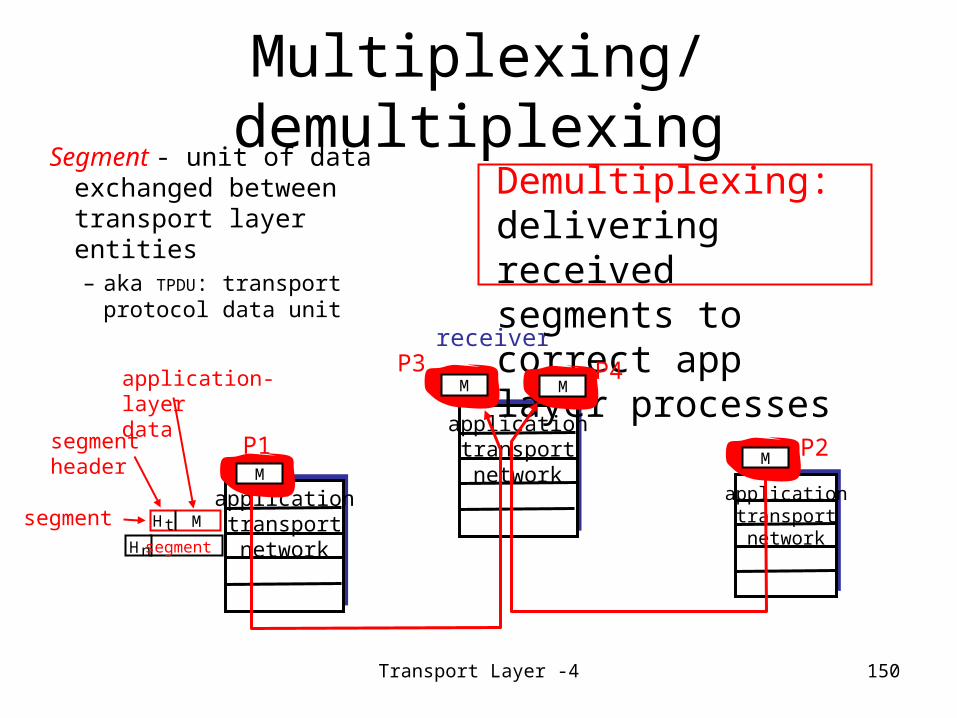
Multiplexing/demultiplexingSegment - unit of data
exchanged between transport layer entities – aka TPDU: transport
protocol data unitreceiver
HtHn
Demultiplexing: delivering received segments to correct app layer processes
segment
segment Mapplicationtransportnetwork
P1M
M MP3 P4
segmentheader
application-layerdata
Transport Layer -5 151
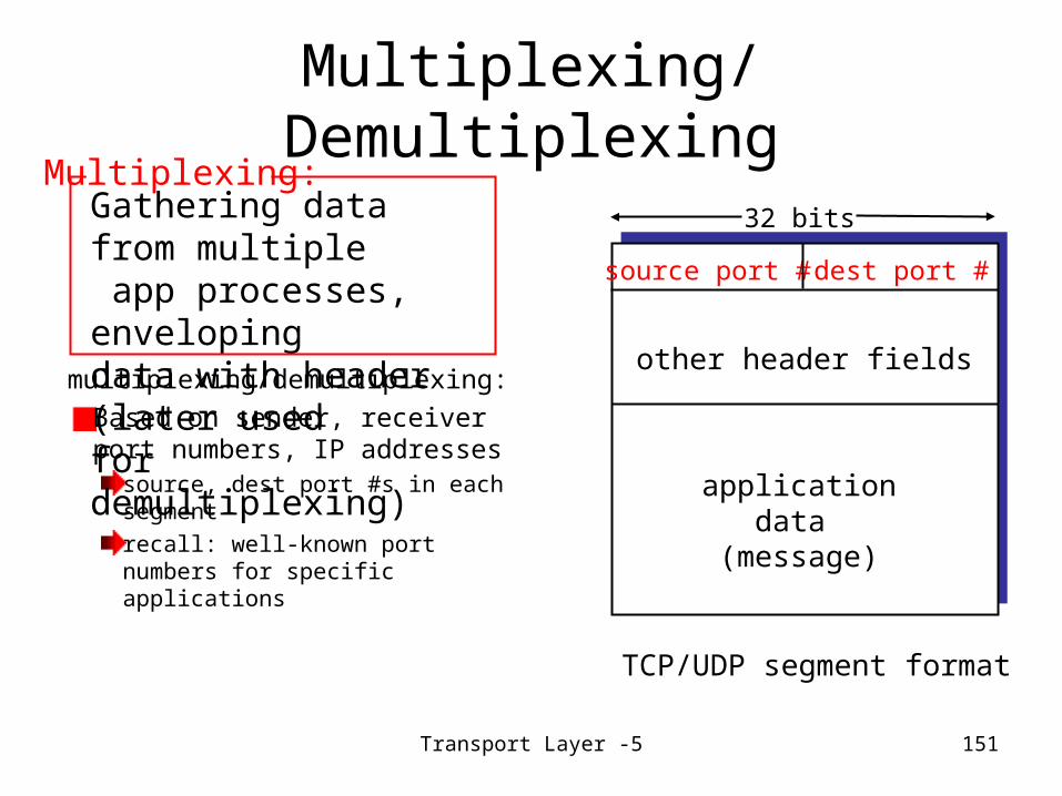
Multiplexing/Demultiplexing
multiplexing/demultiplexing:Based on sender, receiver port numbers, IP addresses
source, dest port #s in each segmentrecall: well-known port numbers for specific applications
Gathering data from multiple app processes, enveloping data with header (later used for demultiplexing)
source port # dest port #
32 bits
applicationdata
(message)
other header fields
TCP/UDP segment format
Multiplexing:

Transport Layer - 6 152
Multiplexing/Demultiplexing: examples
host A server Bsource port: xdest. port: 23
source port:23dest. port: x
port use: simple telnet app
Web clienthost A
Webserver B
Web clienthost C
Source IP: CDest IP: B
source port: x
dest. port: 80
Source IP: CDest IP: B
source port: y
dest. port: 80
port use: Web server
Source IP: ADest IP: B
source port: x
dest. port: 80

Transport Layer - 7 153
UDP: User Datagram Protocol [RFC 768]
“no frills,” “bare bones” Internet transport protocol“best effort” service, UDP segments may be:
lostdelivered out of order to app
connectionless:no handshaking between UDP sender, receivereach UDP segment handled independently of others
Why is there a UDP?no connection establishment (which can add delay)simple: no connection state at sender, receiversmall segment headerno congestion control: UDP can blast away as fast as desired
Transport Layer - 8 154
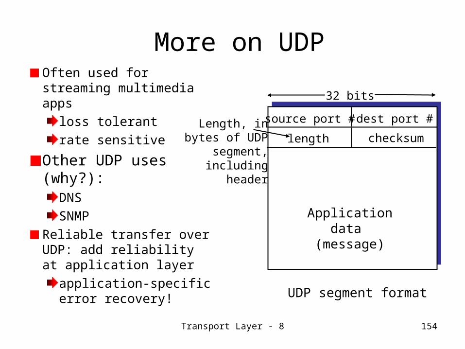
More on UDPOften used for streaming multimedia apps
loss tolerantrate sensitive
Other UDP uses (why?):
DNSSNMP
Reliable transfer over UDP: add reliability at application layer
application-specific error recovery!
source port # dest port #
32 bits
Applicationdata
(message)
UDP segment format
length checksumLength, in
bytes of UDPsegment,including
header

Transport Layer - 9 155
UDP checksum
Sender:Treat segment contents as sequence of 16-bit integersChecksum: addition (1’s complement sum) of segment contentsSender puts checksum value into UDP checksum field
Receiver:Compute checksum of received segmentCheck if computed checksum equals checksum field value:
NO - error detectedYES - no error detected. But maybe errors nonetheless? More later ….
Goal: detect “errors” (e.g., flipped bits) in transmitted segment

Transport Layer - 10 156
Principles of Reliable data transfer
Important in app., transport, link layersTop-10 list of important networking topics!
Characteristics of unreliable channel will determine complexity of reliable data transfer protocol (RDT)
Transport Layer - 11 157
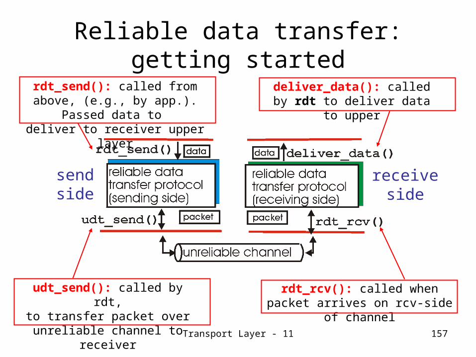
Reliable data transfer: getting started
sendside
receiveside
rdt_send(): called from above, (e.g., by app.). Passed data to deliver to receiver upper layer
udt_send(): called by rdt,to transfer packet over unreliable channel to
receiver
rdt_rcv(): called when packet arrives on rcv-side of channel
deliver_data(): called by rdt to deliver data to
upper

Transport Layer - 12 158
Reliable data transfer: getting started
We’ll:incrementally develop sender, receiver sides of reliable data transfer protocol (rdt)consider only unidirectional data transfer
but control info will flow on both directions!
use finite state machines (FSM) to specify sender, receiver
state1
state2
event causing state transitionactions taken on state transition
state: when in this “state”
next state uniquely
determined by next event
eventactions

Transport Layer - 13 159
Rdt1.0: reliable transfer over a reliable channel
underlying channel perfectly reliableno bit errorsno loss of packets
separate FSMs for sender, receiver:sender sends data into underlying channelreceiver read data from underlying channel

Transport Layer - 14 160
Rdt2.0: channel with bit errorsunderlying channel may flip bits in packet
recall: UDP checksum to detect bit errors
the question: how to recover from errors:acknowledgements (ACKs): receiver explicitly tells sender that pkt received OKnegative acknowledgements (NAKs): receiver explicitly tells sender that pkt had errorssender retransmits pkt on receipt of NAKhuman scenarios using ACKs, NAKs?
new mechanisms in rdt2.0 (beyond rdt1.0):error detectionreceiver feedback: control msgs (ACK,NAK) rcvr->sender

Transport Layer - 15 161
rdt2.0: FSM specification
sender FSM receiver FSM

Transport Layer - 16 162
rdt2.0: in action (no errors)
sender FSM receiver FSM

Transport Layer - 17 163
rdt2.0: in action (error scenario)
sender FSM receiver FSM

Transport Layer - 18 164
rdt2.0 has a fatal flaw!What happens if
ACK/NAK corrupted?sender doesn’t know what happened at receiver!can’t just retransmit: possible duplicate
What to do?sender ACKs/NAKs receiver’s ACK/NAK? What if sender ACK/NAK lost?retransmit, but this might cause retransmission of correctly received pkt!
Handling duplicates: sender adds sequence number to each pktsender retransmits current pkt if ACK/NAK garbledreceiver discards (doesn’t deliver up) duplicate pkt
Sender sends one packet, then waits for receiver response
stop and wait

Transport Layer - 19 165
rdt2.1: sender, handles garbled ACK/NAKs

Transport Layer - 20 166
rdt2.1: receiver, handles garbled ACK/NAKs
Transport Layer - 21 167
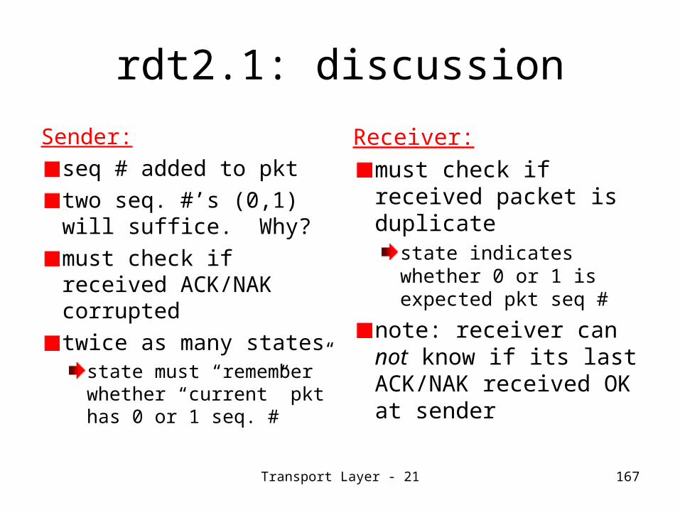
rdt2.1: discussion
Sender:seq # added to pkttwo seq. #’s (0,1) will suffice. Why?must check if received ACK/NAK corrupted twice as many states
state must “remember” whether “current” pkt has 0 or 1 seq. #
Receiver:must check if received packet is duplicate
state indicates whether 0 or 1 is expected pkt seq #
note: receiver can not know if its last ACK/NAK received OK at sender

Transport Layer - 22 168
rdt2.2: a NAK-free protocolsame functionality as rdt2.1, using ACKs onlyinstead of NAK, receiver sends ACK for the last packet received OK
receiver must explicitly include seq # of pkt being ACKed
duplicate ACK at sender results in same action as NAK: retransmit current pkt
senderFSM
!

Transport Layer -23 169
rdt3.0: channels with errors and loss
New assumption: underlying channel can also lose packets (data or ACKs)
checksum, seq. #, ACKs, retransmissions will be of help, but not enough
Q: how to deal with loss?sender waits until certain data or ACK lost, then retransmitsyuck: drawbacks?
Approach: sender waits “reasonable” amount of time for ACK retransmits if no ACK received in this timeif pkt (or ACK) just delayed (not lost):
retransmission will be duplicate, but use of seq. #’s already handles thisreceiver must specify seq # of pkt being ACKed
requires countdown timer

Transport Layer - 24 170
rdt3.0 sender
Transport Layer - 25 171
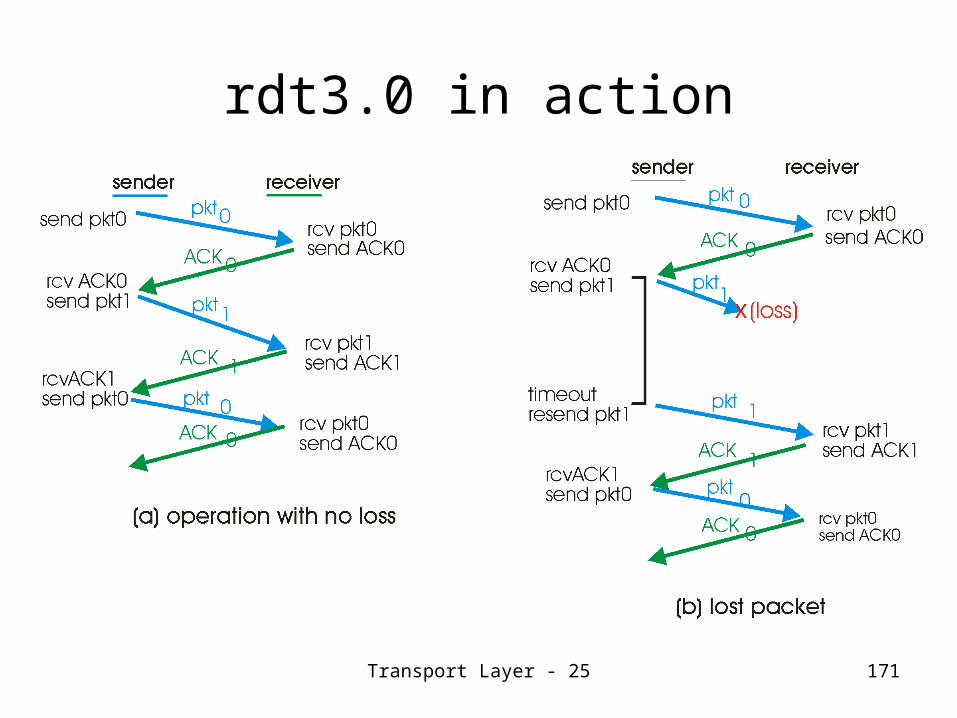
rdt3.0 in action

Transport Layer - 26 172
rdt3.0 in action
Transport Layer - 27 173
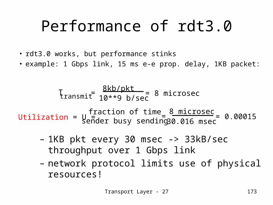
Performance of rdt3.0
• rdt3.0 works, but performance stinks• example: 1 Gbps link, 15 ms e-e prop. delay, 1KB packet:
Ttransmit=8kb/pkt
10**9 b/sec= 8 microsec
Utilization = U = =8 microsec
30.016 msecfraction of time
sender busy sending = 0.00015
– 1KB pkt every 30 msec -> 33kB/sec throughput over 1 Gbps link
– network protocol limits use of physical resources!

Transport Layer - 28 174
Lesson 6: Summary and Follow-up
We had an overview of transport layer services:Multiplexing/de-multiplexingConnectionless and unreliable data transport (UDP)
Connection-oriented and reliable data transport (TCP)
We studied an Incremental Approach to the Design of Reliable Data Transfer Mechanisms (i.e. increasingly complex versions of RDT protocol) in order to:
Get an insight into how industrial products are usually evolved starting with simpler user-models/assumptions and proceeding on with more and more complex ones (big-bangs are rather rare!)Get a perspective on the TCP ‘s reliable data transfer mechanisms
Next class, we study TCP protocol with all the facilities it provides.

175
Lesson 7: TCP

Lesson 7: TCP- 1 176
Lesson 7- TCP: Preview/Objectives
TCP Segment (Message) FormatStudy of Connection-oriented data transport (TCP) with facilities for:
Connection ManagementReliable data transfer with one of the two usual methods:
Go back to NSelective Repeat
Flow ControlCongestion Control
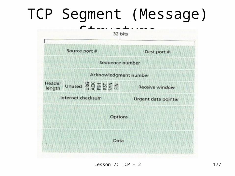
Lesson 7: TCP - 2 177
TCP Segment (Message) Structure
Lesson 7: TCP - 3 178
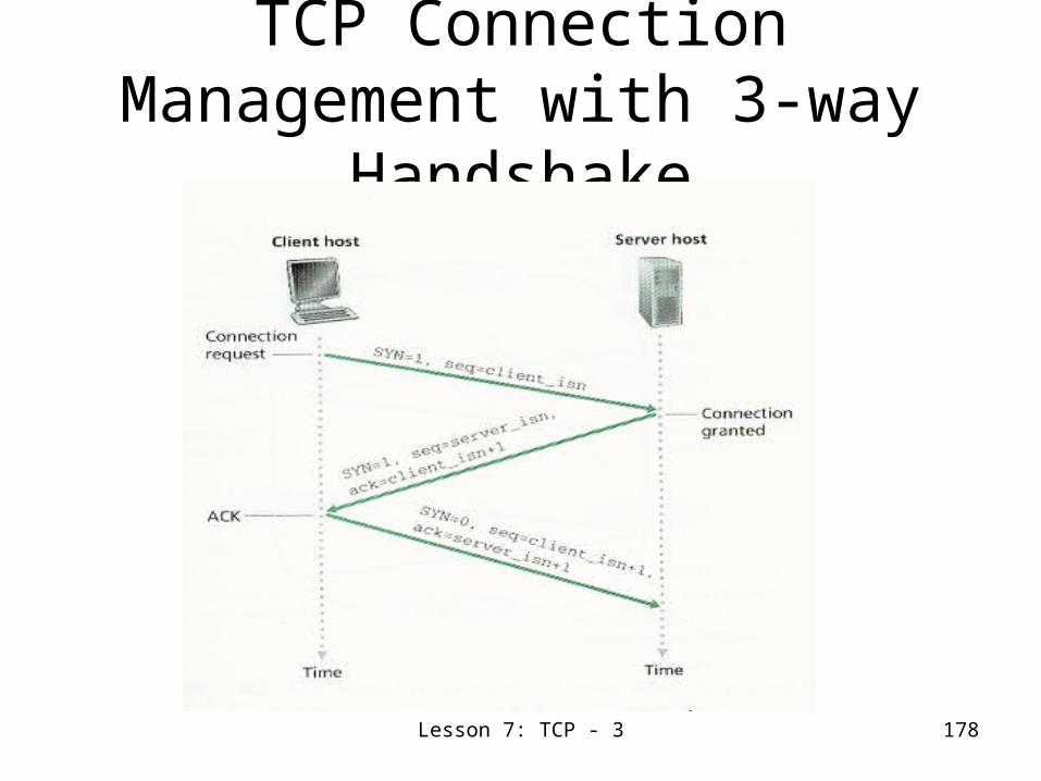
TCP Connection Management with 3-way
Handshake

Lesson 7: TCP - 4 179
TCP Connection Closing Sequence

Lesson 7: TCP - 5 180
TCP Connection Management- Client Side
State Transitions
CLOSING
Receive FIN/ Send ACK
Receive ACK/ Send Nothing
Receive FIN & ACK/ Send ACK
Sharp lines depict unusual states and transitions.
Lesson 7: TCP - 6 181
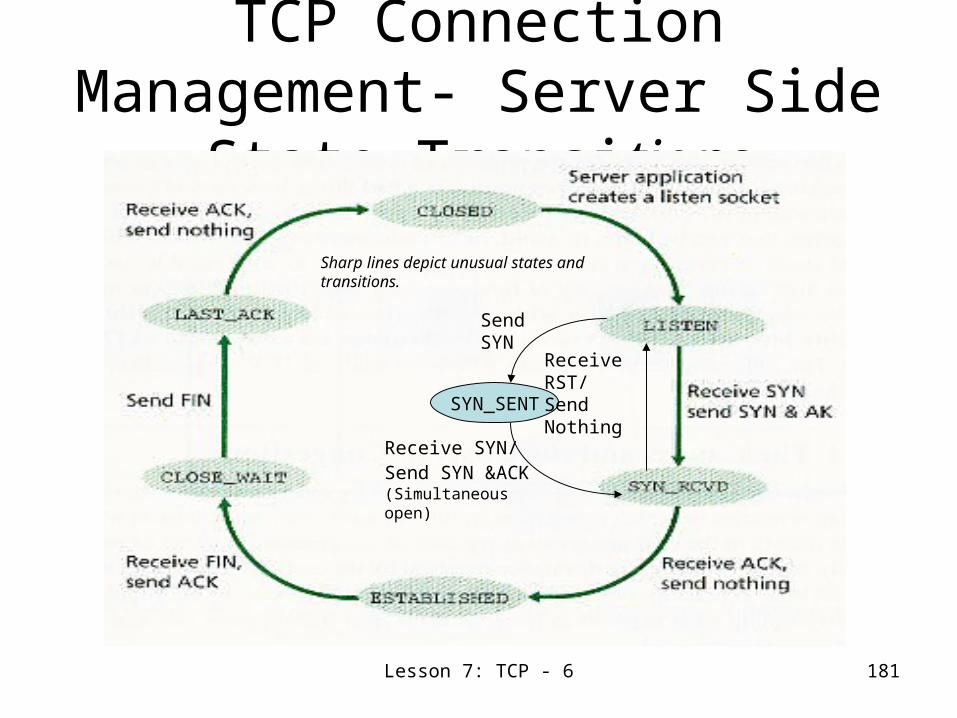
TCP Connection Management- Server Side
State Transitions
SYN_SENT
Send SYN
Receive SYN/ Send SYN &ACK (Simultaneous open)
Receive RST/ Send Nothing
Sharp lines depict unusual states and transitions.

Lesson 7: TCP - 7 182
States of The TCP Connection Management
FSM

Lesson 7: TCP - 8 183
Pipelined protocolsPipelining: sender allows multiple, “in-
flight”, yet-to-be-acknowledged pktsrange of sequence numbers must be increasedbuffering at sender and/or receiver
Two generic forms of pipelined protocols: go-Back-N, selective repeat

Lesson 7: TCP - 9 184
Go-back-N ARQ
It is the most commonly used sliding window protocol! Here, the sender may send a series of frames.The number of unacknowledged frames is determined by the window sizeWhile no errors occur, the receiver will acknowledge the receipt of frames with RR# (receiver ready).A frame in error will be rejected with REJ# and discarded by the receiver.Upon receiving a REJ#, the sender must retransmit the frame in error and all frames that were sent thereafter.
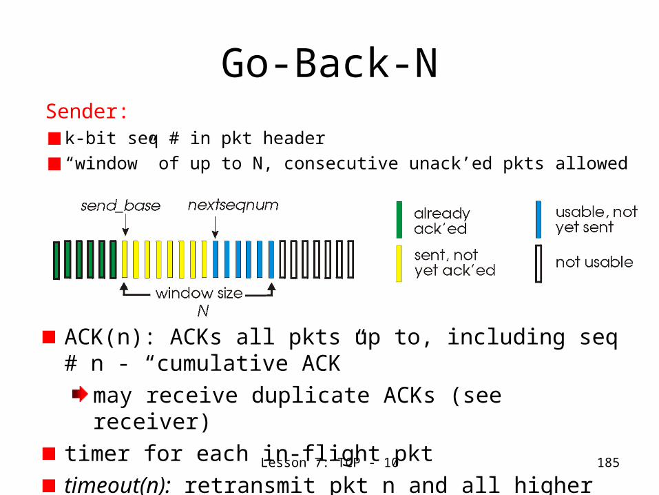
Lesson 7: TCP - 10 185
Go-Back-NSender:
k-bit seq # in pkt header“window” of up to N, consecutive unack’ed pkts allowed
ACK(n): ACKs all pkts up to, including seq # n - “cumulative ACK”
may receive duplicate ACKs (see receiver)timer for each in-flight pkttimeout(n): retransmit pkt n and all higher seq # pkts in window
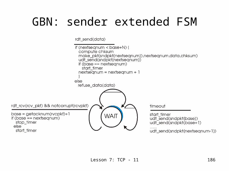
Lesson 7: TCP - 11 186
GBN: sender extended FSM

Lesson 7: TCP - 12 187
GBN: receiver extended FSM
receiver simple:ACK-only: always send ACK for correctly-received pkt with highest in-order seq #
may generate duplicate ACKsneed only remember expectedseqnum
out-of-order pkt: discard (don’t buffer) -> no receiver buffering!ACK pkt with highest in-order seq #

Lesson 7: TCP - 13 188
GBN inaction
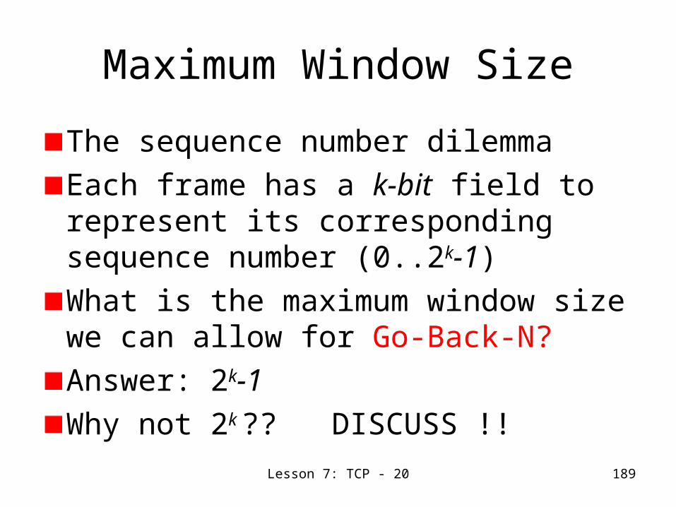
Lesson 7: TCP - 20 189
Maximum Window Size
The sequence number dilemmaEach frame has a k-bit field to represent its corresponding sequence number (0..2k-1)What is the maximum window size we can allow for Go-Back-N?Answer: 2k-1 Why not 2k ?? DISCUSS !!
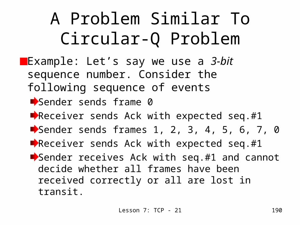
Lesson 7: TCP - 21 190
A Problem Similar To Circular-Q Problem
Example: Let’s say we use a 3-bit sequence number. Consider the following sequence of events
Sender sends frame 0Receiver sends Ack with expected seq.#1Sender sends frames 1, 2, 3, 4, 5, 6, 7, 0Receiver sends Ack with expected seq.#1Sender receives Ack with seq.#1 and cannot decide whether all frames have been received correctly or all are lost in transit.

Lesson 7: TCP - 14 191
Selective Repeat
receiver individually acknowledges all correctly received pkts
buffers pkts, as needed, for eventual in-order delivery to upper layer
sender only resends pkts for which ACK not received
sender timer for each unACKed pkt
sender windowN consecutive seq #’sagain limits seq #s of sent, unACKed pkts

Lesson 7: TCP - 15 192
Selective repeat: sender, receiver windows

Lesson 7: TCP - 16 193
Selective repeat
data from above :if next available seq # in window, send pkt
timeout(n):Send pkt n again, restart timer
ACK(n) in [sendbase,sendbase+N]:
mark pkt n as receivedif n smallest unACKed pkt, advance window base to next unACKed seq #
sender pkt n in [rcvbase, rcvbase+N-1]
send ACK(n)out-of-order: bufferin-order: deliver (also deliver buffered, in-order pkts), advance window to next not-yet-received pkt
pkt n in [rcvbase-N,rcvbase-1]
ACK(n)
otherwise: ignore
receiver

Lesson 7: TCP - 17 194
Selective repeat in action

Lesson 7: TCP - 18 195
Selective repeat:dilemmaExample:
seq #’s: 0, 1, 2, 3window size=3
receiver sees no difference in two scenarios!incorrectly passes duplicate data as new in (a)
Q: what relationship between seq # size and window size?

Lesson 7: TCP - 23 196
Complementary ProblemConsider the following example:
Assume a 3-bit sequence numberSender transmits segments 0-6 to the receiverReceiver gets all the segments in good shape and acknowledges with expected Seq.# 7.Now, lightning strikes and all Acks are lostSender times out and retransmits segment 0The receiver has advanced its window to accept segments 7, 0-5 and since frame 0 is one that is within that range, it is accepted.

Lesson 7: TCP - 24 197
Actual Window Size
The problem shown in the example is that there is an overlap between the sending and receiving windows.Hence, the solution to the window-size problem is to limit the maximum window size to half the range of the sequence number range
That is, for a k-bit sequence number field: 2k-1,
Show that: (MaxSeqNum + 1)/2 = 2k-1.

Lesson 7: TCP - 19 198
Reliable Data Transfer Protocols- A Comparative
StudyStop-and-Wait Protocol
Simple, but performance leaves much to be desired!
Go-Back-NBetter performance, but more complicated. Possibly wasteful if large blocks of packets need to be retransmitted
Selective RepeatA pain to implement – needs multiple timers, but better performance through individual packet management

Lesson 7: TCP - 22 199
Selective-Reject ARQ
In this ARQ mechanism the sender only retransmits those frames for which a negative ACK (SREJ) has been received or for that timed out.The receiver does not discard frames which are delivered out of order.
Question: What about the permissible window size?

Lesson 7: TCP - 25 200
Flow Control in TCP
RcvWindow = RcvBuffer – [LastByteRcvd – LastByteRead] LastByteSent – LastByteAcked <= RcvWindow Possible Blocking @ Sender -> TCP Solution?

Lesson 7: TCP - 26 201
Silly Window Syndrome
Sender is slow- Sends a byte at a timeNetwork bandwidth badly usedNagle’s algorithm- Wait, bunch and sendAdvisable to disable in interactive applications- cursor movement may look erratic and make user unhappy
Receiver is slow- Takes a byte at a time for an interactive application
Clarke’s solution- wait till a decent amount of space is available and advertise the receiver window size,Complementary to Nagle’s and both can work together

Lesson 7: TCP - 27 202
General Congestion Control Mechanisms
End to End Congestion ControlNetwork-assisted Congestion Control
Direct feedback from router with a choke packetRouter marks a field in packet. Upon receipt of the packet, receiver sends a notification to the sender. (Full RTT required!)
Network-assisted Congestion not possible in TCP as there is no support from IP.

Lesson 7: TCP - 28 203
Congestion Control in TCPThree components of TCP congestion control algorithm
Additive Increase Multiplicative Decrease
Slow start
Reaction to timeout events
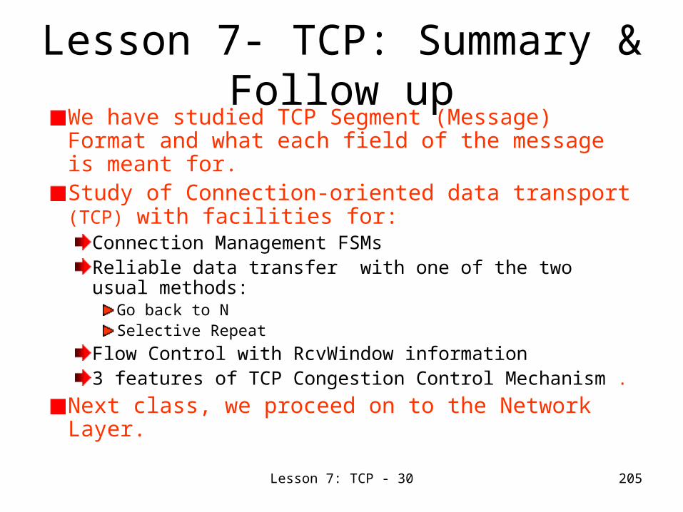
Lesson 7: TCP - 30 205
Lesson 7- TCP: Summary & Follow up
We have studied TCP Segment (Message) Format and what each field of the message is meant for.Study of Connection-oriented data transport (TCP) with facilities for:
Connection Management FSMsReliable data transfer with one of the two usual methods:
Go back to NSelective Repeat
Flow Control with RcvWindow information3 features of TCP Congestion Control Mechanism .
Next class, we proceed on to the Network Layer.

206
Lesson 8: Introduction to Network Layer

Lesson 8: Introduction to Network Layer - 1
207
Lesson 8- Introduction to Network Layer:
Preview/ObjectivesOverview of network layer functionsForwardingRoutingCall setup (sometimes)
Network Models- Virtual Circuits versus Datagram NetworksRouting Algorithms
Desirable CharacteristicsClassificationDifferent known typesOverview of graph theory based algorithms

Lesson 8: Introduction to Network Layer - 2
208
Network layer functions
Three important functions: Switching- Moving packets (frames) that come into a switch interface and forward them on the interface that leads to the destination. Switching implies forwarding- ability to determine the interface to which a frame should be directed. Switching has more of hardware connotation and forwarding refers to software aspect.
Routing: Determination of path or route taken by packets from source to destination. There exist many routing algorithms for doing this. As against forwarding which refers to transfer of packets from an incoming link to an outgoing link, routing refers collective interaction via routing protocols for path determination.
Call setup: some network architectures require router call setup along path before data flows
networkdata linkphysical
networkdata linkphysical
networkdata linkphysical
networkdata linkphysical
networkdata linkphysical
networkdata linkphysical
networkdata linkphysical
networkdata linkphysical
application
transportnetworkdata linkphysical
application
transportnetworkdata linkphysical
Network layer protocols exist in every switch whether host (end system) or router (intermediate switch).

Lesson 8: Introduction to Network Layer - 3
209
Network service model
Q: What service model for “channel” transporting packets from sender to receiver?guaranteed bandwidth?preservation of inter-packet timing (no jitter)?loss-free delivery?in-order delivery?congestion feedback to sender?
? ??virtual circuit
or datagram?
The most important abstraction provided
by network layer:
serv
ice a
bst
ract
ion

Lesson 8: Introduction to Network Layer - 4
210
Virtual circuits
call setup for each call before data can flow and teardowneach packet carries VC identifier (not destination host OD)every router on source-dest path s maintain “state” for each passing connection
transport-layer connection only involved two end systems
link, router resources (bandwidth, buffers) may be allocated to VC
to get circuit-like performance.
“source-to-dest path behaves much like telephone circuit”
performance-wisenetwork actions along source-to-destination path

Lesson 8: Introduction to Network Layer - 5
211
Virtual circuits: signaling protocols
used to setup, maintain teardown VCused in ATM, frame-relay, X.25not used in today’s Internet
application
transportnetworkdata linkphysical
application
transportnetworkdata linkphysical
1. Initiate call 2. incoming call
3. Accept call4. Call connected5. Data flow begins 6. Receive data

Lesson 8: Introduction to Network Layer - 6
212
Datagram networks: the Internet model
no call setup at network layerrouters: no state about end-to-end connections
no network-level concept of “connection”
packets typically routed using destination host IDpackets between same source-dest pair may take different paths
application
transportnetworkdata linkphysical
application
transportnetworkdata linkphysical
1. Send data 2. Receive data

Lesson 8: Introduction to Network Layer - 7
213
Network layer service models:
NetworkArchitecture
Internet
ATM
ATM
ATM
ATM
ServiceModel
best effort
CBR
VBR
ABR
UBR
Bandwidth
none
constantrateguaranteedrateguaranteed minimumnone
Loss
no
yes
yes
no
no
Order
no
yes
yes
yes
yes
Timing
no
yes
yes
no
no
Congestionfeedback
no (inferredvia loss)nocongestionnocongestionyes
no
Guarantees ?
Internet model being extented: Intserv, Diffserv
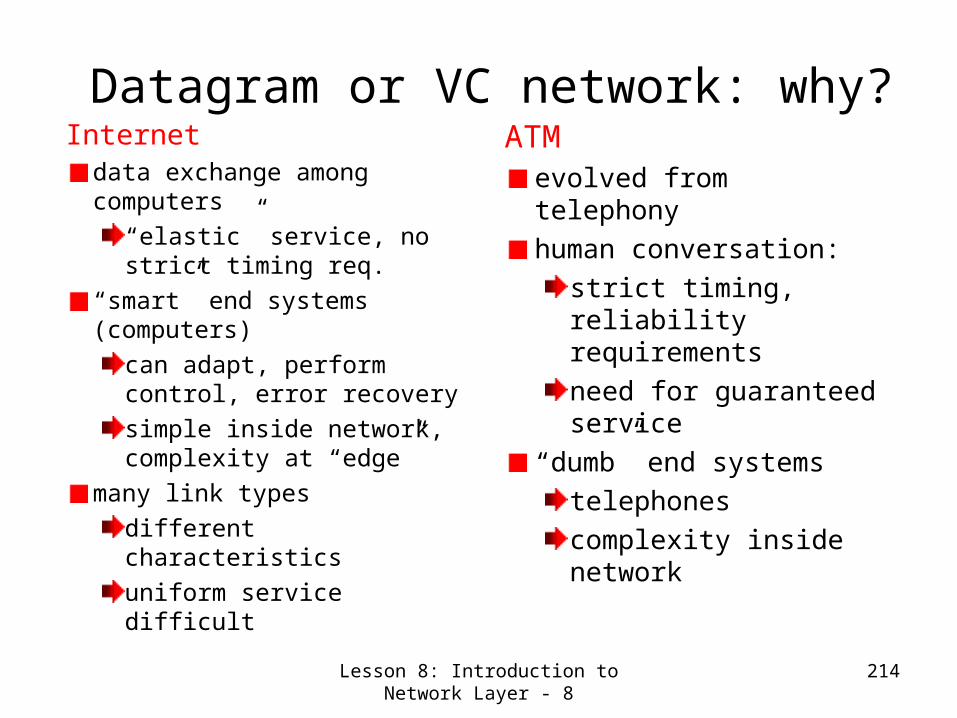
Lesson 8: Introduction to Network Layer - 8
214
Datagram or VC network: why?Internet
data exchange among computers
“elastic” service, no strict timing req.
“smart” end systems (computers)
can adapt, perform control, error recoverysimple inside network, complexity at “edge”
many link types different characteristicsuniform service difficult
ATMevolved from telephonyhuman conversation:
strict timing, reliability requirementsneed for guaranteed service
“dumb” end systemstelephonescomplexity inside network
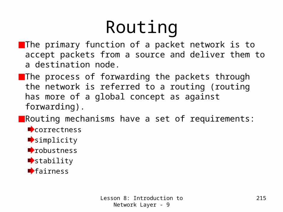
Lesson 8: Introduction to Network Layer - 9
215
RoutingThe primary function of a packet network is to accept packets from a source and deliver them to a destination node.The process of forwarding the packets through the network is referred to a routing (routing has more of a global concept as against forwarding).Routing mechanisms have a set of requirements:
correctnesssimplicityrobustnessstabilityfairness

Lesson 8: Introduction to Network Layer - 10
216
Routing (Continued)Most important:
optimalityefficiency
Routing directly impacts the performance of the network! WHY?In order to route packets on optimal routes through the network to their destinations, we must first decide what is to be optimized:
delaycostthroughput

Lesson 8: Introduction to Network Layer - 11
217
Routing InformationRouting decisions are generally based on some knowledge of the state of the network.
Delay on certain linksCost through certain nodesPacket lossetc.
This information may have to be dynamically collected. This leads to overhead which in turn reduces the utilization.

Lesson 8: Introduction to Network Layer - 12
218
Routing Algorithms
Graph abstraction for routing algorithms:graph nodes are routersgraph edges are physical links
link cost: delay, $ cost, or congestion level
Goal: determine “good” path
(sequence of routers) thru network from source to
dest.
Routing Algorithm
A
ED
CB
F
2
2
13
1
1
2
53
5
“good” path:typically means minimum cost pathother definitions possible
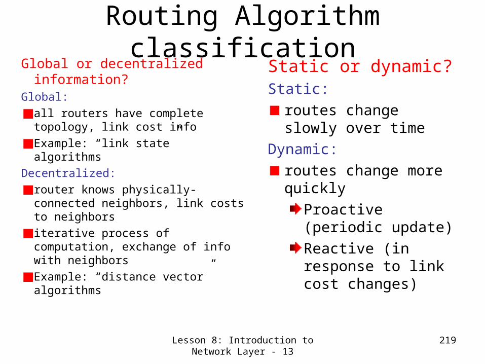
Lesson 8: Introduction to Network Layer - 13
219
Routing Algorithm classification
Global or decentralized information?
Global:all routers have complete topology, link cost infoExample: “link state” algorithms
Decentralized: router knows physically-connected neighbors, link costs to neighborsiterative process of computation, exchange of info with neighborsExample: “distance vector” algorithms
Static or dynamic?Static:
routes change slowly over time
Dynamic: routes change more quickly
Proactive (periodic update)Reactive (in response to link cost changes)
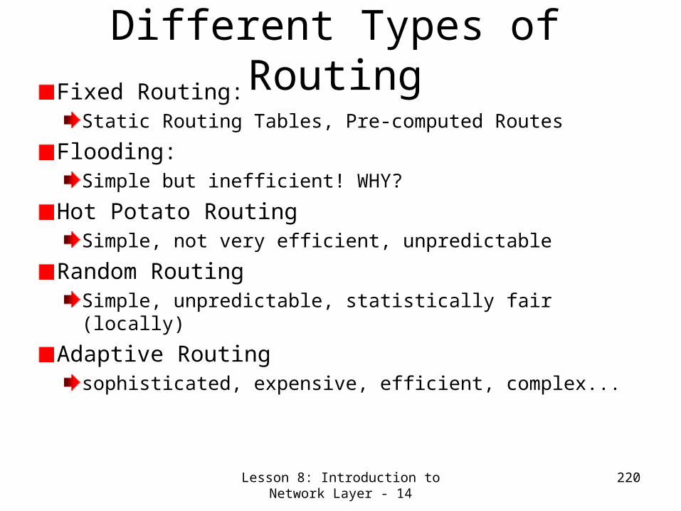
Lesson 8: Introduction to Network Layer - 14
220
Different Types of RoutingFixed Routing:
Static Routing Tables, Pre-computed Routes
Flooding:Simple but inefficient! WHY?
Hot Potato RoutingSimple, not very efficient, unpredictable
Random RoutingSimple, unpredictable, statistically fair (locally)
Adaptive Routingsophisticated, expensive, efficient, complex...

Lesson 8: Introduction to Network Layer - 15
221
Random RoutingSometimes called probabilistic routing!Here, the probability of a packet being forwarded on a particular link is a function of conditions on this link.
– Pi = Probability of link i being selected
– Ri = Data rate on link i
j j
ii R
RP

Lesson 8: Introduction to Network Layer - 16
222
Random Routing (Continued)
Note: Random Routing is probabilistic, i.e., the link with the largest capacity may not be the one chosen for every transmission.
We can formulate a static and dynamic (adaptive) version of the routing algorithm.
Can you think of other measurements (metrics) to compute Pi ?

Lesson 8: Introduction to Network Layer - 17
223
Adaptive RoutingAdaptive Routing Techniques are used in almost all packet-switching networks.
ARPANET
Routing decisions change in response to changes in the network.
Network FailureCongestion
Adaptive routing strategies can improve performance.Adaptive routing strategies can aid congestion control.
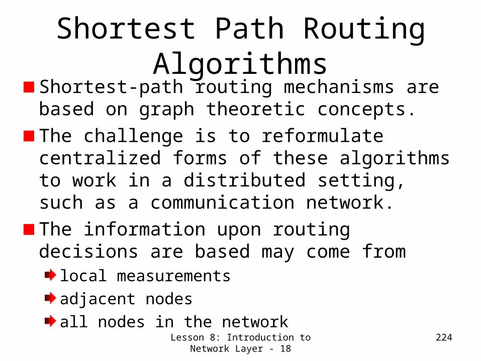
Lesson 8: Introduction to Network Layer - 18
224
Shortest Path Routing Algorithms
Shortest-path routing mechanisms are based on graph theoretic concepts.The challenge is to reformulate centralized forms of these algorithms to work in a distributed setting, such as a communication network.The information upon routing decisions are based may come from
local measurementsadjacent nodesall nodes in the network
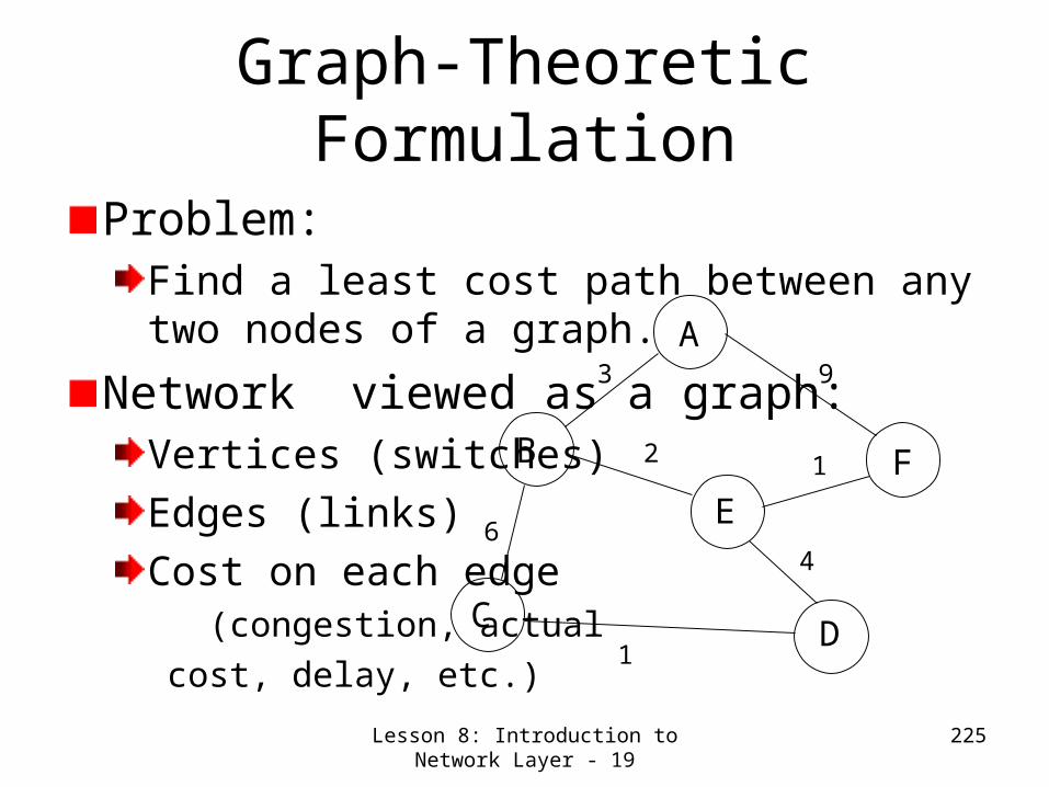
Lesson 8: Introduction to Network Layer - 19
225
Graph-Theoretic Formulation
Problem:Find a least cost path between any two nodes of a graph.
Network viewed as a graph:Vertices (switches)Edges (links)Cost on each edge (congestion, actualcost, delay, etc.)
D
FE
A
B
C
4
9
12
1
6
3
Lesson 8: Introduction to Network Layer - 20
226
Some of the established shortest-path algorithms in traditional graph theory are:
Dijkstra’s shortest path algorithmBellman-Ford AlgorithmFloyd-Warshall Algorithm
The main difference between the algorithms is the type of augmentation through each iteration.
Dijkstra: nodesBellman-Ford: number of arcs (links) in the pathFloyd-Warshall: set of nodes in the path (all s-d pairs)
These algorithms have been formulated in a centralized manner and must be mapped into a distributed environment.

Lesson 8: Introduction to Network Layer - 21
227
Lesson 8- Introduction to Network Layer: Summary and Follow-up
We had an overview of network layer functionsForwardingRoutingCall setup (sometimes)
In passing studied the subtle differences between switching, forwarding and routing. We made a comparative study of Network Models- Virtual Circuits versus Datagram NetworksWe looked into the following aspects of Routing Algorithms
Desirable CharacteristicsClassificationDifferent known typesOverview of graph theory based algorithms
In the next class, we study in detail some of the shortest path routing algorithms.

228
Lesson 9: Routing Algorithms for Network Layer

Lesson 9: Routing Algorithms for Network Layer - 1
229
Lesson 9: Routing Algorithms for Network Layer- Preview/Objectives
We study two routing algorithmsDikstra’s link State algorithmDistance vector (Bellman Ford) algorithm
We work out examples
We discuss the count-to-infinity problem

Lesson 9: Routing Algorithms for Network Layer - 2
230
A Link-State Routing AlgorithmDijkstra’s algorithm
net topology, link costs known to all nodes
accomplished via “link state broadcast” all nodes have same info
computes least cost paths from one node (‘source”) to all other nodes
gives routing table for that nodeiterative: after k iterations, know least cost path to k dest.’s
Notation:c(i,j): link cost from node i to j. cost infinite if not direct neighbors
D(v): current value of cost of path from source to destination V
p(v): predecessor node along path from source to v, that is next v
N: set of nodes whose least cost path definitively known

Lesson 9: Routing Algorithms for Network Layer - 3
231
Dijsktra’s Algorithm
1 Initialization: 2 N = {A} 3 for all nodes v 4 if v adjacent to A 5 then D(v) = c(A,v) 6 else D(v) = infinity 7 8 Loop 9 find w not in N such that D(w) is a minimum 10 add w to N 11 update D(v) for all v adjacent to w and not in N: 12 D(v) = min( D(v), D(w) + c(w,v) ) 13 /* new cost to v is either old cost to v or known 14 shortest path cost to w plus cost from w to v */ 15 until all nodes in N

Lesson 9: Routing Algorithms for Network Layer - 4
232
Dijkstra’s Algorithm: An Example
Step012345
start NA
ADADE
ADEBADEBC
ADEBCF
D(B),p(B)2,A2,A2,A
D(C),p(C)5,A4,D3,E3,E
D(D),p(D)1,A
D(E),p(E)infinity
2,D
D(F),p(F)infinityinfinity
4,E4,E4,E
A
ED
CB
F
2
2
13
1
1
2
53
5

Lesson 9: Routing Algorithms for Network Layer - 5
233
A Discussion on Dijkstra’s algorithmAlgorithm complexity: n nodes
• each iteration: need to check all nodes, w, not in N (the set)• n*(n+1)/2 comparisons: O(n**2)• more efficient implementations possible: O(nlogn)
Oscillations possible:• e.g., link cost = amount of carried traffic
A
D
C
B1 1+e
e0
e
1 1
0 0
A
D
C
B2+e 0
001+e1
A
D
C
B0 2+e
1+e10 0
A
D
C
B2+e 0
e01+e1
initially … recomputerouting
… recompute … recompute

Lesson 9: Routing Algorithms for Network Layer - 6
234
Bellman-Ford (Distance Vector)The algorithm iterates on # of arcs in a path.The original algorithm is a single destination shortest path algorithm.Let D(h)
i be the shortest ( h) path length from node i to node 1 (the destination).By definition, D(h)
1= 0 h.Assumptions:
There exists at least one path from every node to the destinationAll cycles not containing the destination have nonnegative length (cost).
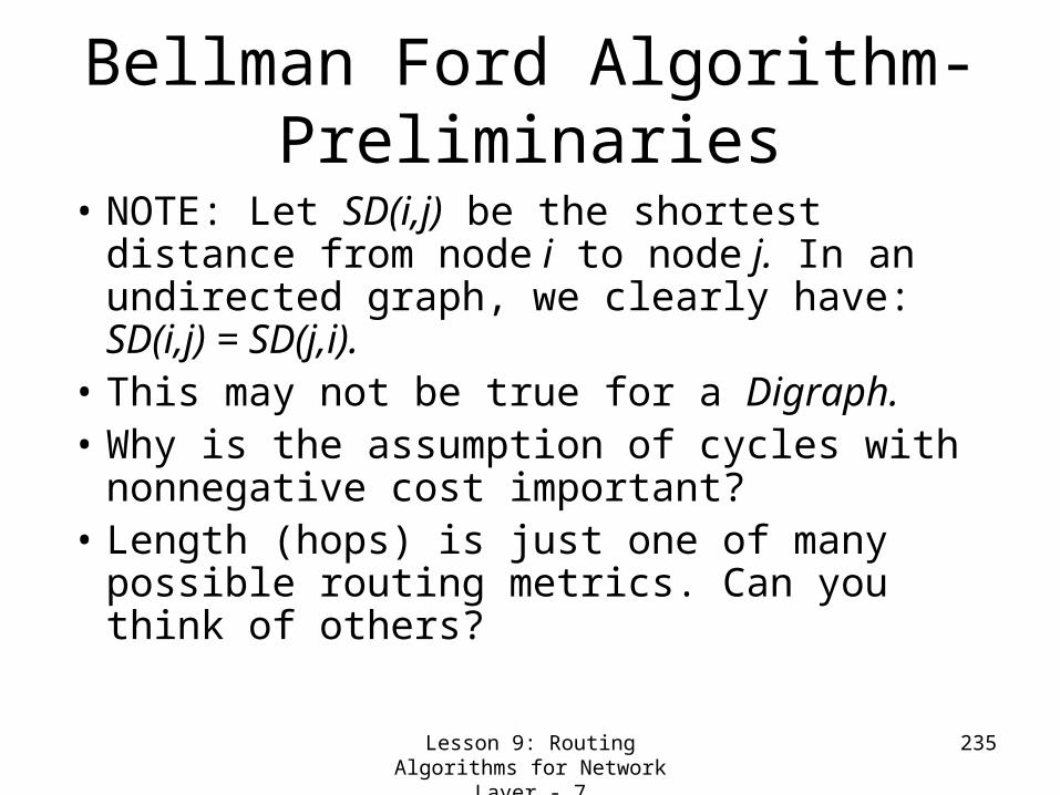
Lesson 9: Routing Algorithms for Network Layer - 7
235
Bellman Ford Algorithm- Preliminaries
• NOTE: Let SD(i,j) be the shortest distance from node i to node j. In an undirected graph, we clearly have: SD(i,j) = SD(j,i).
• This may not be true for a Digraph.• Why is the assumption of cycles with
nonnegative cost important?• Length (hops) is just one of many
possible routing metrics. Can you think of others?

Lesson 9: Routing Algorithms for Network Layer - 8
236
Bellman-Ford Algorithm• The Bellman-Ford Algorithm:
– Step 1: Set D(0)i = i
– Step 2: For each h 0 compute D(h+1)i as
D(h+1)i = minj[D(h)
j + dj,i] i 1
– where dj,i is the cost (length) of link lj,i
• We say that the algorithm has terminated when D(h)
i = D(h-1)i i
• In a network with N nodes, the algorithm terminates after at most N iterations!

Lesson 9: Routing Algorithms for Network Layer - 9
237
Distance Vector Routing Algorithm
Iterative:• continues until no
nodes exchange info.• self-terminating: no
“signal” to stop
Asynchronous:• nodes need not
exchange info/iterate in lock step!
Distributed:• each node
communicates only with directly-attached neighbors
Distance Table data structure • each node has its own• row for each possible destination• column for each directly-
attached neighbor to node• example: in node X, for
destination Y via neighbor Z:
D (Y,Z)X
distance from X toY, via Z as next hop
c(X,Z) + min {D (Y,w)}Z
w
=
=

Lesson 9: Routing Algorithms for Network Layer - 10
238
Distance Table: An Example
A
E D
CB7
8
1
2
1
2 D ()
A
B
C
D
A
1
7
6
4
B
14
8
9
11
D
5
5
4
2
Ecost to destination via
Des
tinat
ionD (C,D)
Ec(E,D) + min {D (C,w)}
Dw=
= 2+2 = 4
D (A,D)E
c(E,D) + min {D (A,w)}D
w== 2+3 = 5
D (A,B)E
c(E,B) + min {D (A,w)}B
w== 8+6 = 14
loop!
loop!

Lesson 9: Routing Algorithms for Network Layer - 11
239
Distance table gives routing table
D ()
A
B
C
D
A
1
7
6
4
B
14
8
9
11
D
5
5
4
2
Ecost to destination via
dest
inat
ion
A
B
C
D
A,1
D,5
D,4
D,2
Outgoing link to use, cost
dest
inat
ion
Distance table Routing table

Lesson 9: Routing Algorithms for Network Layer - 12
240
Distance Vector Routing: An Overview
Iterative, asynchronous: each local iteration caused by:
• local link cost change • message from neighbor:
its least cost path change from neighbor
Distributed:• each node notifies
neighbors only when its least cost path to any destination changes– neighbors then notify their
neighbors if necessary
wait for (change in local link cost of msg from neighbor)
recompute distance table
if least cost path to any dest has changed, notify neighbors
Each node:

Lesson 9: Routing Algorithms for Network Layer - 13
241
Distance Vector Algorithm
1 Initialization:
2 for all adjacent nodes v:
3 D (*,v) = infty /* the * operator means "for all rows" */
4 D (v,v) = c(X,v)
5 for all destinations, y
6 send min D (y,w) to each neighbor /* w over all X's neighbors */
X
X
Xw
At all nodes, X:

Lesson 9: Routing Algorithms for Network Layer - 14
242
Distance Vector Algorithm (cont.)8 loop
9 wait (until I see a link cost change to neighbor V
10 or until I receive update from neighbor V) 11
12 if (c(X,V) changes by d) 13 /* change cost to all dest's via neighbor v by d */ 14 /* note: d could be positive or negative */ 15 for all destinations y: D (y,V) = D (y,V) + d 16
17 else if (update received from V wrt destination Y) 18 /* shortest path from V to some Y has changed */ 19 /* V has sent a new value for its min DV(Y,w) */ 20 /* call this received new value is "newval" */ 21 for the single destination y: D (Y,V) = c(X,V) + newval 22
23 if we have a new min D (Y,w) for any destination Y 24 send new value of min D (Y,w) to all neighbors 25
26 forever
w
XX
X
X
X
w
w

Lesson 9: Routing Algorithms for Network Layer - 15
243
Distance Vector Algorithm: An Example
X Z12
7
Y

Lesson 9: Routing Algorithms for Network Layer - 16
244
Distance Vector Algorithm: example (contd.)
X Z12
7
Y
D (Y,Z)X
c(X,Z) + min {D (Y,w)}w=
= 7+1 = 8
Z
D (Z,Y)X
c(X,Y) + min {D (Z,w)}w=
= 2+1 = 3
Y
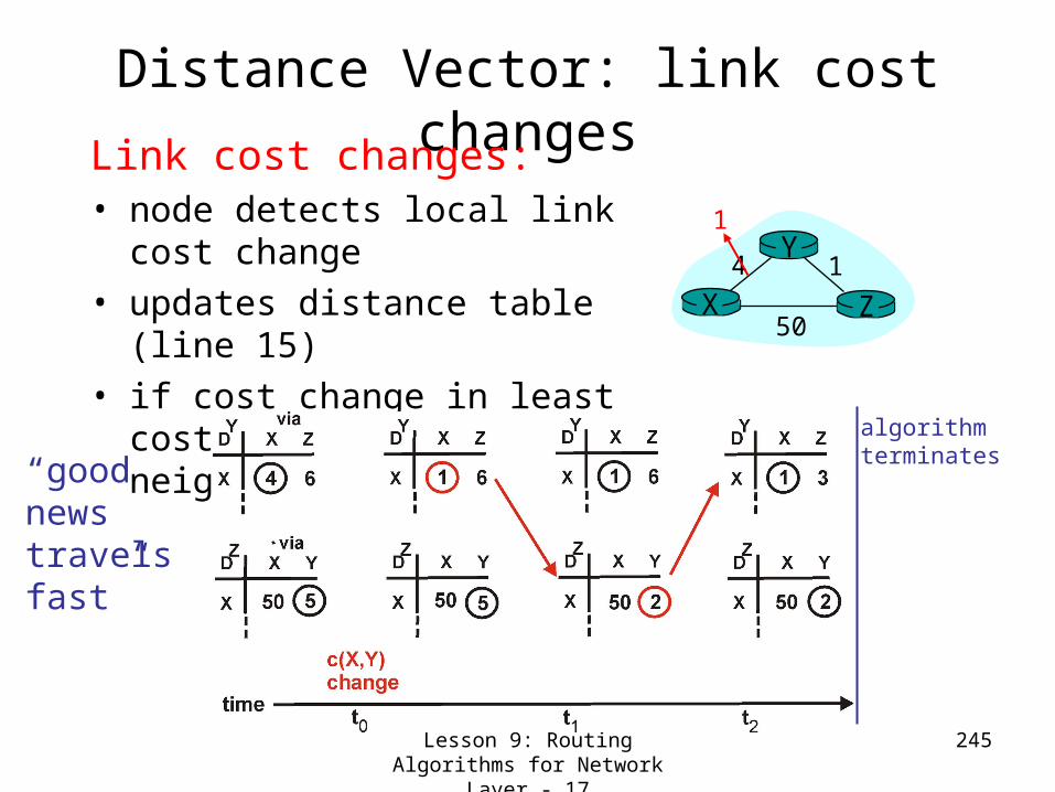
Lesson 9: Routing Algorithms for Network Layer - 17
245
Distance Vector: link cost changesLink cost changes:• node detects local link cost
change • updates distance table (line
15)• if cost change in least cost
path, notify neighbors (lines 23,24)
X Z14
50
Y1
algorithmterminates“good
news travelsfast”

Lesson 9: Routing Algorithms for Network Layer - 18
246
Distance Vector: link cost changes
Link cost changes:• good news travels
fast • bad news travels
slow - “count to infinity” problem!
X Z14
50
Y60
algorithmcontinues
on!

Lesson 9: Routing Algorithms for Network Layer - 19
247
Distance Vector: poisoned reverseIf Z routes through Y to get
to X :• Z tells Y its (Z’s) distance to X
is infinite (so Y won’t route to X via Z)
• will this completely solve count to infinity problem?
X Z14
50
Y60
algorithmterminates
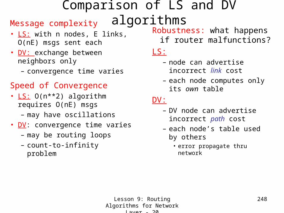
Lesson 9: Routing Algorithms for Network Layer - 20
248
Comparison of LS and DV algorithmsMessage complexity• LS: with n nodes, E links,
O(nE) msgs sent each • DV: exchange between
neighbors only– convergence time varies
Speed of Convergence• LS: O(n**2) algorithm
requires O(nE) msgs– may have oscillations
• DV: convergence time varies– may be routing loops– count-to-infinity problem
Robustness: what happens if router malfunctions?
LS: – node can advertise
incorrect link cost– each node computes only
its own table
DV:– DV node can advertise
incorrect path cost– each node’s table used by
others • error propagate thru
network
Lesson 9: Routing Algorithms for Network Layer - 21
249
Lesson 9: Routing Algorithms for Network Layer- Summary
and Follow-upWe studied two routing algorithms
Dikstra’s link State algorithmDistance vector (Bellman-Ford) algorithm
• We work ed out examples
• We discussed the count-to-infinity problem
• Next class, we continue with more on Internet & IP

250
Lesson 10: IP & The Internet

Lesson 10: IP & The Internet - 1 251
Lesson 10: IP & The Internet- Preview/Objectives
We see how the Internet- the network of networks works
Study the IP message and address structures
We study a number of Protocols & AlgorithmsICMPARP & RARP/BOOTP/DHCPRIP /OSPF & BGP
We discuss how the count-to-infinity problem is addressed in the BGP.

Lesson 10: IP & The Internet - 2 252
The Internet
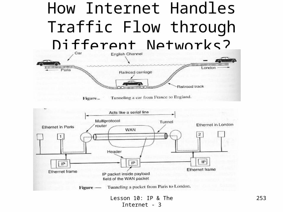
Lesson 10: IP & The Internet - 3 253
How Internet Handles Traffic Flow through Different
Networks?

Lesson 10: IP & The Internet - 4 254
The IP Message FormatHeader Length in 32-bit words
Don’t Fragment (e.g. Memory Image)
More Fragments (All but the last have it !)
Variable Length field (in multiples of 32-bits) meant for inclusion by subsequent versions new Info.
Original Options: Security, strict source routing, loose source coding (gives list of routers not to be missed), Timestamp (enforces each router to append its address & Timestamp- useful for debugging)
Originally had Delay, Throughput and
Reliability flags. Now it has 4 queuing priority classes, 3 discard probabilities and historical service classes.
Tells whether to give the datagram to TCP or UDP or some other process.
Tells to which datagram the newly arrived fragment belongs.
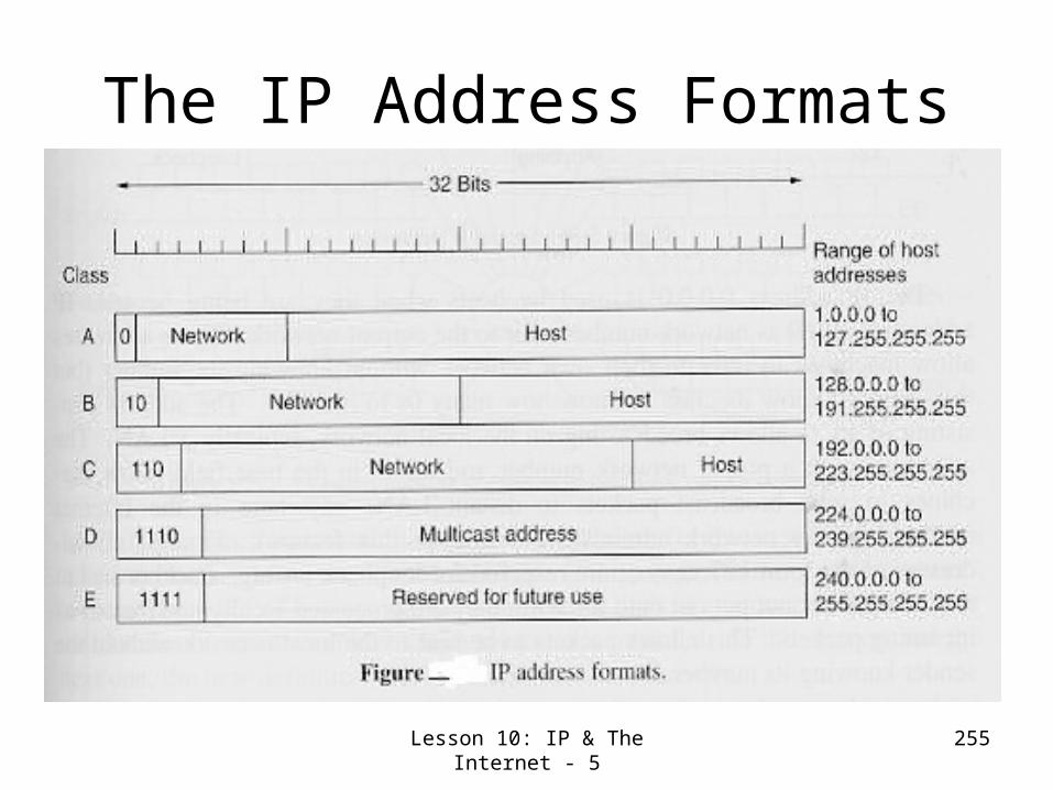
Lesson 10: IP & The Internet - 5 255
The IP Address Formats
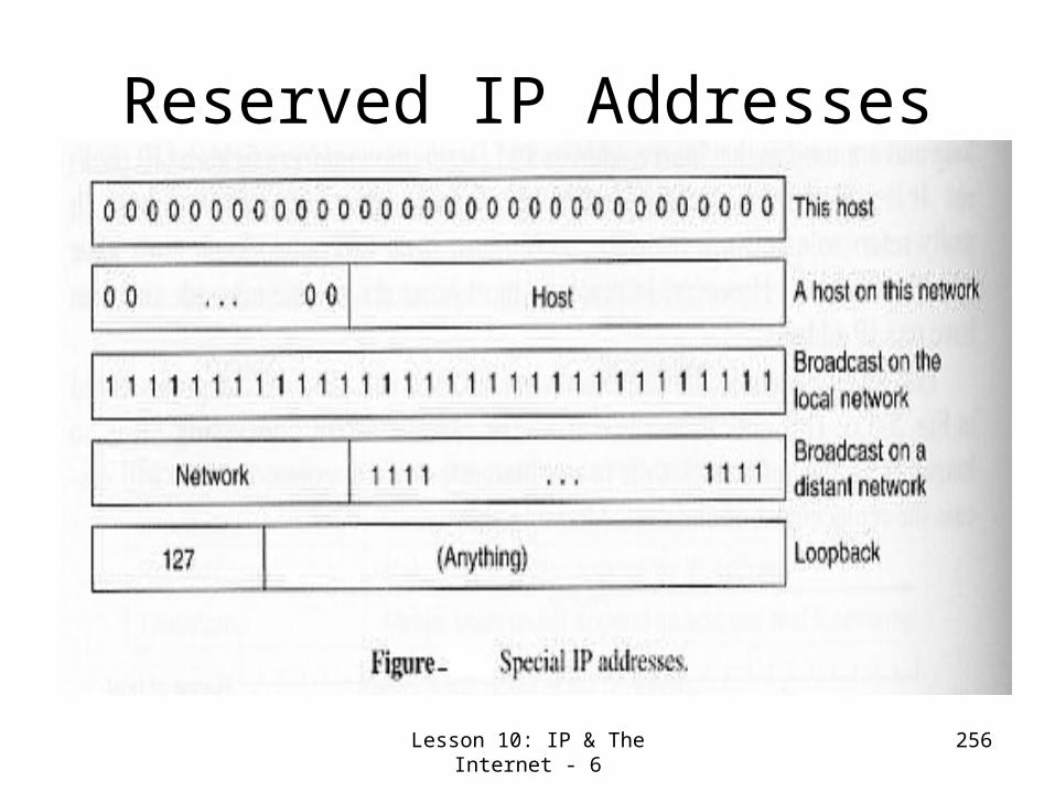
Lesson 10: IP & The Internet - 6 256
Reserved IP Addresses

Lesson 10: IP & The Internet - 7 257
The Internet Network layer
routingtable
Host, router network layer functions:
Routing protocols•path selection•ARP, RARP/BOOTP/ DHCP•RIP/OSPF, BGP
IP protocol•addressing conventions•datagram format•packet handling conventions
ICMP protocol•error reporting•router “signaling”
Transport layer: TCP, UDP
Link layer
physical layer
Networklayer

Lesson 10: IP & The Internet - 8 258
The Internet Control Message Protocol
Each ICMP message is encapsulated in an IP packet

ARP (Address Resolution Protocol)
• Used in IPV4 (over Ethernet) to get the hardware/link/MAC address of the machine with IP address
• ARP message of the form “I am X1.X2.X3.X4, tell me who is Y1.Y2,Y3,Y4 is sent using LAN (say, ETHERNET) broadcast address (all 1’s) in an ethernet packet.
• Only the concerned system sends ARP response; others discard.
Lesson 1: History of Computer Networks - 2
259
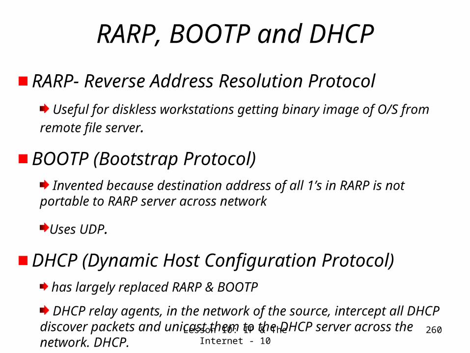
Lesson 10: IP & The Internet - 10 260
RARP, BOOTP and DHCP
RARP- Reverse Address Resolution Protocol Useful for diskless workstations getting binary image of O/S
from remote file server.
BOOTP (Bootstrap Protocol) Invented because destination address of all 1’s in RARP is
not portable to RARP server across network
Uses UDP.
DHCP (Dynamic Host Configuration Protocol) has largely replaced RARP & BOOTP
DHCP relay agents, in the network of the source, intercept all DHCP discover packets and unicast them to the DHCP server across the network. DHCP.
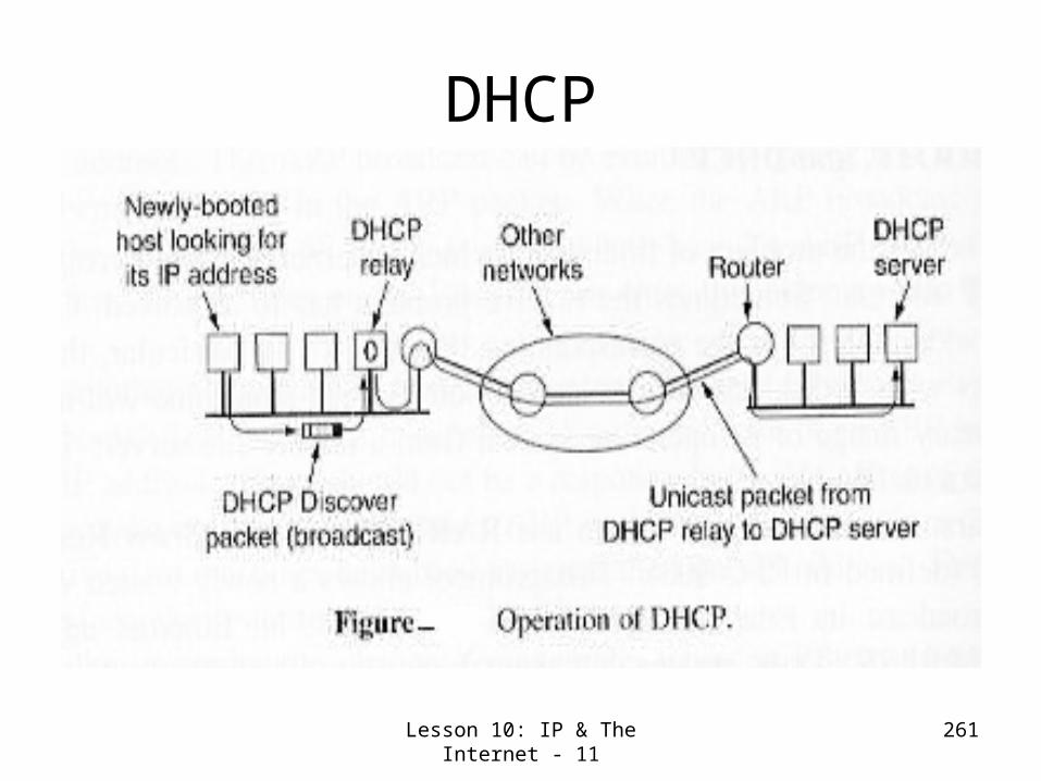
Lesson 10: IP & The Internet - 11 261
DHCP

Lesson 10: IP & The Internet - 12 262
OSPF (Open Shortest Path First)
Interior Gateway Protocol for
routing within Autonomous Systems (ASes).
It Supports
point-to-point routing between two routers
multi-access networks with Broadcasting (e.g. LANs) and
multi-access networks without broad casting (e.g. WANs).

Lesson 10: IP & The Internet - 13 263
OSPF (Open Shortest Path First) Interior Gateway Protocol (routing within Autonomous Systems (ASes).
Supports- point-to-point routing between two routers, multi-access networks with Broadcasting (e.g. LANs) and multi-access networks without broad casting (e.g. WANs).

Lesson 10: IP & The Internet - 14 264
OSPF (Continued)Original Interior gateway protocol was RIP (Routing Information Protocol) based on the Bellman-Ford algorithm in ARPANET. Now replaced by an extension of the LS algorithm. It is open, dynamic (adaptable to changes), supports other metrics e.g. delay, routing based on types of service, hierarchical systems, security, tunneling, and does load balancing

Lesson 10: IP & The Internet - 15 265
BGP (Boarder Gateway Protocol) Exterior Gateway Protocol used between ASes
Uses Distance Vector (DV) routing, but solves the count to infinity problem by keeping track paths , not just the costs to destination.
Policies based on political, security or economic considerations configured into BGP routers by Scripts.

Lesson 10: IP & The Internet - 16 266
Lesson 10: IP & The Internet- Summary and Follow-up
We have seen how the Internet- the network of networks works (particularly, the tunneling concept)We Studied the IP message and address structuresWe studied a number of Protocols & Algorithms
ICMPARP & RARP/BOOTP/DHCPRIP /OSPF & BGP
We discussed how the count-to-infinity problem is addressed in the BGP.
Next class, we proceed on to Data-link layer.

267
Lesson 11: Introduction to Data
Link Layer

Lesson 11: Introduction to Data Link Layer - 1
268
Lesson 11: Introduction to Data Link Layer -Preview/ObjectivesWe study the principles behind various link layer services such as
Error Detection and correctionMultiple access (sharing the broadcast channel)
Point-to-point (Single wire e.g. SLIP/PPP)Broadcast (Shared wire e.g. Ethernet, WaveLan etc.Switched (e.g. Switched Ethernet, ATM, etc.)
Link layer Addressing (ARP- already done!)Reliable Data Transfer & Flow control (already done in the context of TCP)
We study Pure and Slotted Protocols- precursors of CSMA/CD
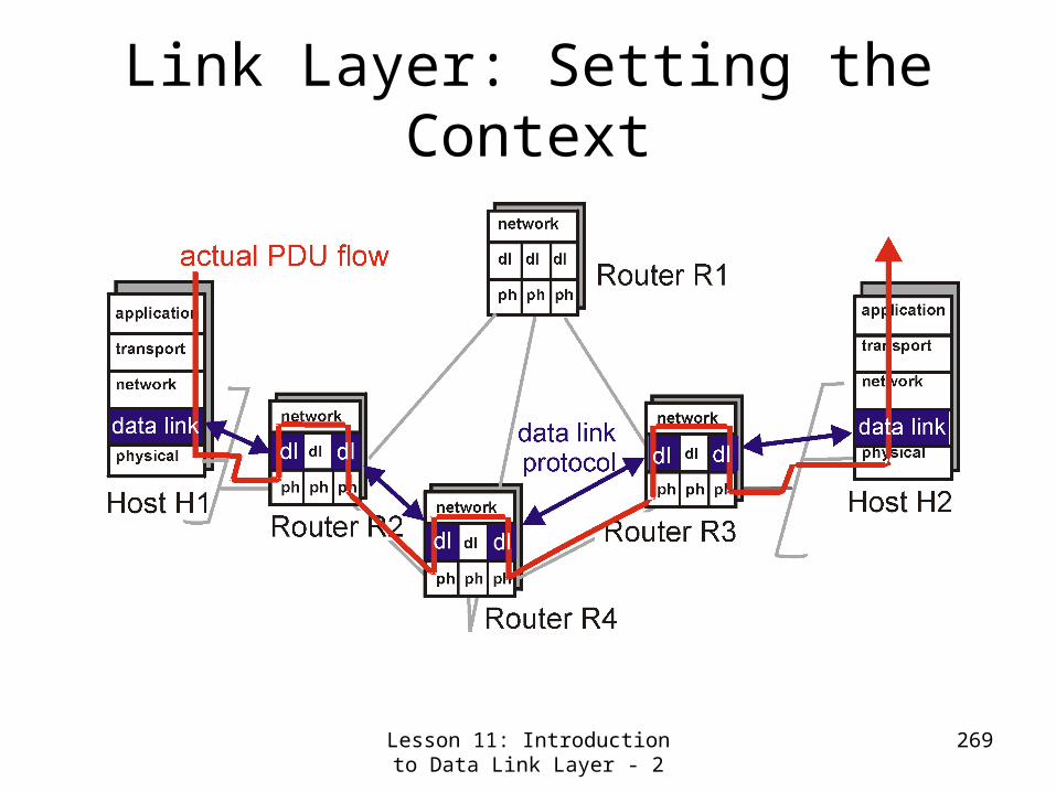
Lesson 11: Introduction to Data Link Layer - 2
269
Link Layer: Setting the Context

Lesson 11: Introduction to Data Link Layer - 3
270
Link Layer & Data Link Protocol
• two physically connected devices:– host-router, router-router, host-host
• unit of data: frame
applicationtransportnetwork
linkphysical
networklink
physical
M
M
M
M
Ht
HtHn
HtHnHl MHtHnHl
framephys. link
data linkprotocol
adapter card

Lesson 11: Introduction to Data Link Layer - 4
271
Link Layer ServicesFraming and link access:
encapsulate datagram into frame, adding header, trailerimplement channel access if shared medium, ‘physical addresses’ used in frame headers to identify source and destination
different from IP address!
Reliable delivery between two physically connected devices:
we learned how to do this already (in the context of TCP)!seldom used on low bit error link (fiber, some twisted pair)wireless links: high error rates
Q: why both link-level and end-end reliability?
Lesson 11: Introduction to Data Link Layer - 5
272
More Link Layer ServicesFlow Control:
pacing between sender and receivers
Error Detection: errors caused by signal attenuation, noise. receiver detects presence of errors and
signals sender for retransmission or drops frame
Error Correction: receiver identifies and corrects bit error(s) without resorting to retransmission

Lesson 11: Introduction to Data Link Layer - 6
273
Link Layer: Implementationimplemented in “adapter”
e.g., PCMCIA card, Ethernet card typically includes: RAM, DSP chips, host bus interface, and link interface
applicationtransportnetwork
linkphysical
networklink
physical
M
M
M
M
Ht
HtHn
HtHnHl MHtHnHl
framephys. link
data linkprotocol
adapter card

Lesson 11: Introduction to Data Link Layer - 7
274
Error Detection in Link Layer
Error Detection: Parity bit (single bit indication, but even number of flips can’t be detected)Check Sum is simple, but not enough (even number of flips in the opposite direction give the same value) Cyclic Redundancy Check is more rigorous and hence used in link layerTransport layer relies on this and manages with simpler Check Sum.
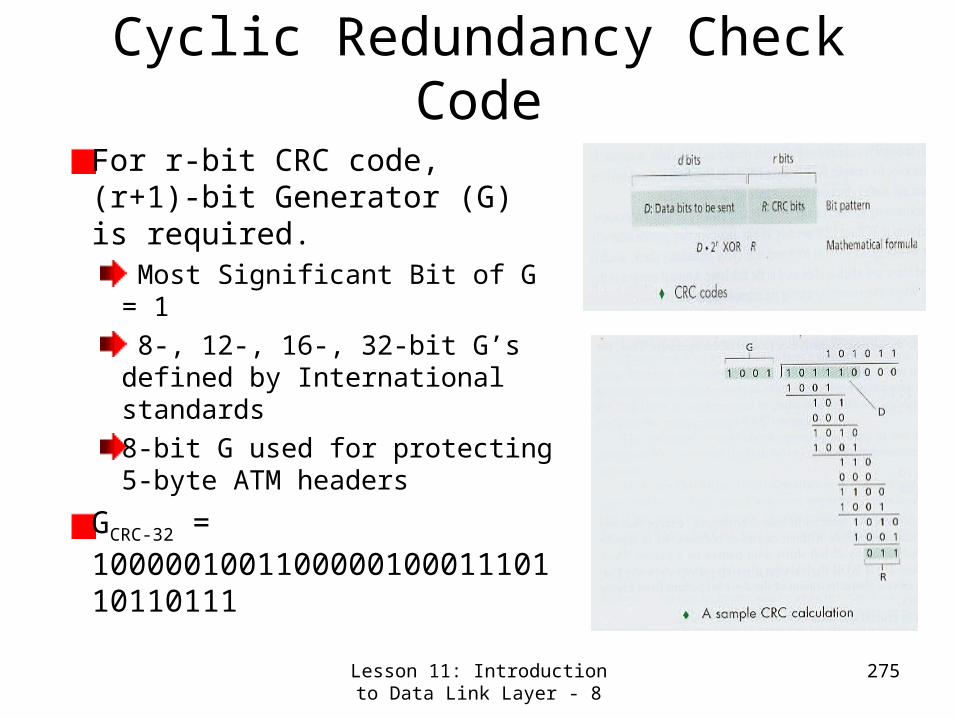
Lesson 11: Introduction to Data Link Layer - 8
275
Cyclic Redundancy Check Code
For r-bit CRC code, (r+1)-bit Generator (G) is required.
Most Significant Bit of G = 1 8-, 12-, 16-, 32-bit G’s defined by International standards8-bit G used for protecting 5-byte ATM headers
GCRC-32 = 100000100110000010001110110110111

Lesson 11: Introduction to Data Link Layer - 9
276
More About CRCCRC is also known as polynomial codeCRC Formula Derivation:D.2r XOR R = n G D.2r = n G XOR R R = remainder (D.2r/G ) when subtraction in the division is
done by XOR.
CRC can detect Burst errors (consecutive bit errors) of size < r+1 Under some assumptions, bust errors of size > r+1 can be detected with probability 1 – 0.5 r
Each CRC standard can detect any odd number of bit errors.
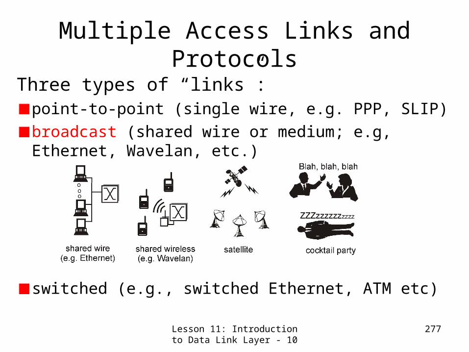
Lesson 11: Introduction to Data Link Layer - 10
277
Multiple Access Links and Protocols
Three types of “links”:point-to-point (single wire, e.g. PPP, SLIP)broadcast (shared wire or medium; e.g, Ethernet, Wavelan, etc.)
switched (e.g., switched Ethernet, ATM etc)
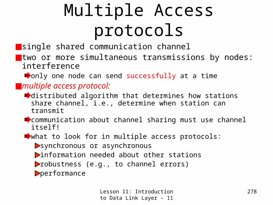
Lesson 11: Introduction to Data Link Layer - 11
278
Multiple Access protocolssingle shared communication channel two or more simultaneous transmissions by nodes: interference
only one node can send successfully at a time
multiple access protocol:distributed algorithm that determines how stations share channel, i.e., determine when station can transmitcommunication about channel sharing must use channel itself! what to look for in multiple access protocols:
synchronous or asynchronous information needed about other stations robustness (e.g., to channel errors) performance

Lesson 11: Introduction to Data Link Layer - 12
279
MAC Protocols: A Taxonomy
Three broad classes:Channel Partitioning
divide channel into smaller “pieces” (time slots, frequency)allocate piece to node for exclusive use
Random Accessallow collisions“recover” from collisions
“Taking turns”tightly coordinate shared access to avoid collisionsGoal: efficient, fair, simple, decentralized

Lesson 11: Introduction to Data Link Layer - 13
280
Random Access protocolsWhen node has packet to send
transmit at full channel data rate R.no a priori coordination among nodes
two or more transmitting nodes -> “collision”,random access MAC protocol specifies:
how to detect collisionshow to recover from collisions (e.g., via delayed retransmissions)
Examples of random access MAC protocols:slotted ALOHAALOHACSMA and CSMA/CD

Lesson 11: Introduction to Data Link Layer - 14
281
Pure (Unslotted) ALOHA
Users are not synchronized.Each user transmits a data packet when ready.In the event of two or more packets collide (overlap in time), each user involved realized this and retransmit the packet after a randomized delay.

Lesson 11: Introduction to Data Link Layer - 15
282
Pure ALOHA (Continued)• unslotted Aloha: simpler, no
synchronization• packet needs transmission:
– send without awaiting for beginning of slot
• collision probability includes two overlapping intervals:– packet sent at t0 collide with other packets
sent in [t0-1, t0+1]

Lesson 11: Introduction to Data Link Layer - 16
283
Slotted ALOHA
Like Pure-ALOHA with additional requirements:
The channel is slotted in timeEach user is required to synchronize the start of packet transmission to coincide with the slot boundary (only complete collision would occur, avoid partial collision)

Lesson 11: Introduction to Data Link Layer - 17
284
Slotted Aloha - Further Details• time is divided into equal size slots (=
packet trans. time)• node with new arriving packets: transmit
at beginning of next slot • if collision: retransmit packet in future
slots with probability p, until successful.
Success (S), Collision (C), Empty (E) slots
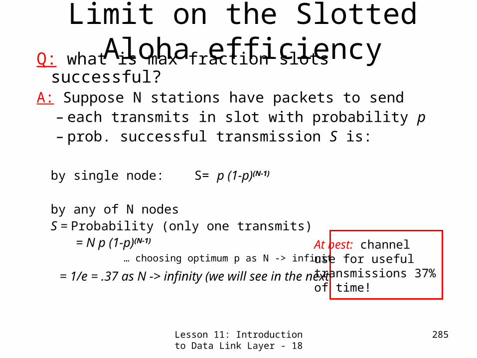
Lesson 11: Introduction to Data Link Layer - 18
285
Limit on the Slotted Aloha efficiencyQ: what is max fraction slots successful?
A: Suppose N stations have packets to send– each transmits in slot with probability p– prob. successful transmission S is:
by single node: S= p (1-p)(N-1)
by any of N nodes
S = Probability (only one transmits) = N p (1-p)(N-1)
… choosing optimum p as N -> infinity ...
= 1/e = .37 as N -> infinity (we will see in the next slide)
At best: channeluse for useful transmissions 37%of time!

Lesson 11: Introduction to Data Link Layer - 19
286
Derivation of Slotted Aloha efficiency Limit
S = Probability of success of any of the N nodes (i.e. only one transmits)
= N p (1-p)(N-1)
Find the maximum value of S using the established formula:
Solution: Setting ds/dp = 0, we get,N. (1-p)(N-1) _ N p (N-1) (1-p)(N-2) = 0
p = 1/N
Putting this value “p” in S and taking limits we get,S = 1/e
eNLim
N
N
111

Lesson 11: Introduction to Data Link Layer - 20
287
Pure & Slotted Aloha Efficiency LimitsP(success by given node) = P(node transmits) .
P(no other node transmits in [p0-1,p0] .
P(no other node transmits in [p0,p0+1]
= p . (1-p)(N-1) .(1-p)(N-1)
P(success by any of N nodes) = N p . (1-p)(N-1). (1-p)(N-1)
… choosing optimum p as N ->
infty ...
= 1/(2e) using similar derivation
= .18
S =
thro
ughput
=
“goodput”
(
succ
ess
rate
)
G = offered load = Np0.5 1.0 1.5 2.0
0.1
0.2
0.3
0.4
Pure Aloha
Slotted Aloha protocol constrainseffective channelthroughput!

Lesson 11: Introduction to Data Link Layer - 21
288
Lesson 11: Introduction to Data Link Layer –Summary & Follow-up
We studied the principles behind various link layer services e.g.
Error Detection and correctionMultiple access (sharing the broadcast channel)
Point-to-point (Single wire e.g. SLIP/PP)Broadcast (Shared wire e.g. Ethernet, WaveLan etc.Switched (e.g. Switched Ethernet, ATH, etc.)
Link layer AddressingReliable Data Transfer & Flow control (already done in the TCP class)
We studied and analyzed Pure and Slotted ALOHA Protocols- precursors of CSMA/CD.
Next class, we proceed on to Link layer technologies and study CSMA/CD, Ethernet and other protocols & Technologies.

289
Lesson 12: Link Layer Technologies

Lesson 12: Link Layer Technologies - 1
290
Lesson 12: Link Layer Technologies-Preview/Objectives
We study specific link layer technologies and their implementation
Current Multiple Access MAC (Medium Access Control) Protocols-
CSMA/CDChannel Partitioning“Taking Turns” type – Token Ring
Ethernet Hubs, Bridges and SwitchesPPPATMIEEE 802.11 LANs

Lesson 12: Link Layer Technologies - 2
291
Carrier Sense Multiple Access (CSMA)
Used in radio network.Propagation delay is small compared to packet transmission time.Avoid collision by listening to the carrier before transmission.

Lesson 12: Link Layer Technologies - 3
292
CSMA: Carrier Sense Multiple Access)
CSMA: listen before transmit:If channel sensed idle: transmit entire packet
If channel sensed busy, defer transmission Persistent CSMA: retry immediately with probability p when channel becomes idle (may cause instability)Non-persistent CSMA: retry after random interval
human analogy: don’t interrupt others! Good Manners protocol.

Lesson 12: Link Layer Technologies - 4
293
CSMA collisions
Collisions can occur:Propagation delay means two nodes may not yethear each other’s transmissionCollision:Entire packet transmission time wasted
spatial layout of nodes along ethernet
Note:Role of distance and propagation delay in determining collision probability.

Lesson 12: Link Layer Technologies - 5
294
CSMA/CD (Collision Detection)
CSMA/CD: carrier sensing, deferral as in CSMAcollisions detected within short timecolliding transmissions aborted, reducing channel wastage persistent or non-persistent retransmission
Collision detection: easy in wired LANs: measure signal strengths, compare transmitted, received signalsdifficult in wireless LANs: receiver shut off while transmitting
Same human analogy of the polite conversationalist

Lesson 12: Link Layer Technologies - 6
295
IEEE 802.3 CSMA/CDUses 1-persistent CSMA algorithm.Rules:
if the channel is idle then transmitif the channel is busy, then continue to listen until idle then transmit immediatelyif a collision is detected during the transmission, immediately cease transmitting the frame and transmit a jamming signal to ensure everyone knows the collision, hence the name collision detection (CD)After transmitting the jamming signal, then wait a random time and attempt to transmit again

Lesson 12: Link Layer Technologies - 7
296
CSMA/CD Collision Detection

Lesson 12: Link Layer Technologies - 8
297
“Taking Turns” MAC protocols
Channel partitioning MAC protocols:share channel efficiently at high loadinefficient at low load: delay in channel access, 1/N bandwidth allocated even if only 1 active node!
Random access MAC protocolsefficient at low load: single node can fully utilize channelhigh load: collision overhead
“Taking turns” protocolslook for best of both worlds!
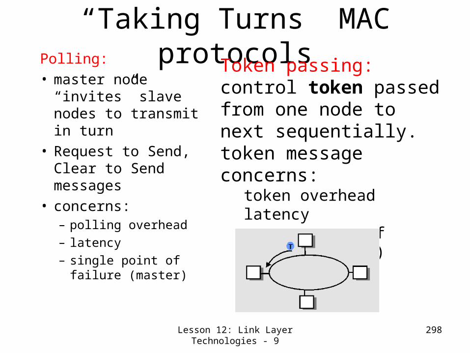
Lesson 12: Link Layer Technologies - 9
298
“Taking Turns” MAC protocolsPolling:
• master node “invites” slave nodes to transmit in turn
• Request to Send, Clear to Send messages
• concerns:– polling overhead – latency– single point of failure
(master)
Token passing:control token passed from one node to next sequentially.token messageconcerns:
token overhead latencysingle point of failure (token)
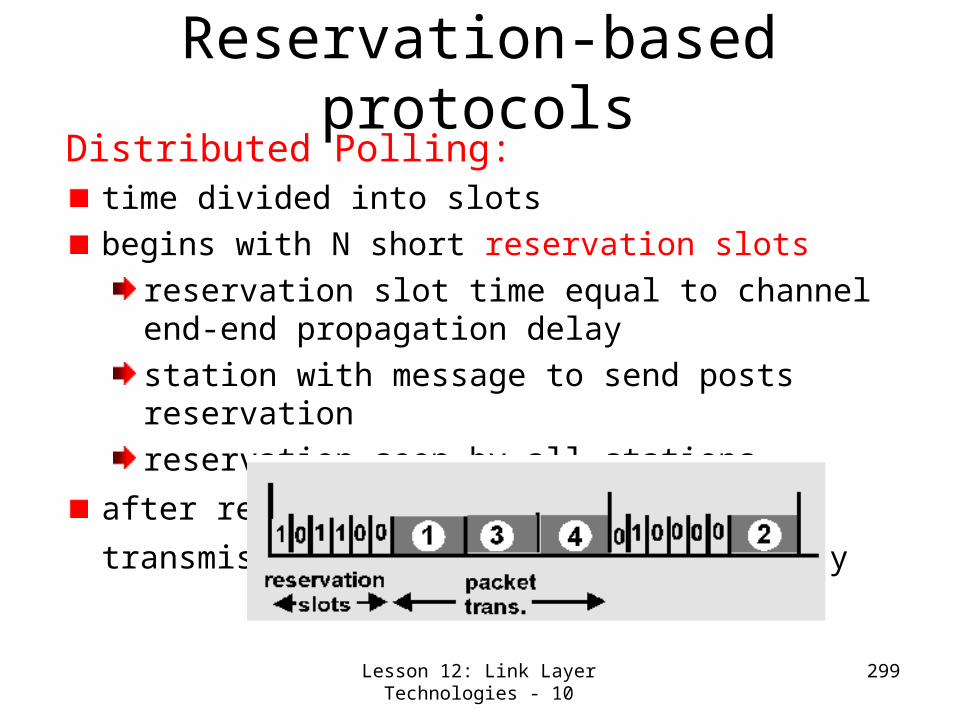
Lesson 12: Link Layer Technologies - 10
299
Reservation-based protocolsDistributed Polling:
time divided into slotsbegins with N short reservation slots
reservation slot time equal to channel end-end propagation delay station with message to send posts reservationreservation seen by all stations
after reservation slots, message transmissions
ordered by known priority

Lesson 12: Link Layer Technologies - 11
300
Summary of MAC protocols
What can we do with a shared media? Channel Partitioning, by time, frequency or code
Time Division,Code Division, Frequency Division
Random partitioning (dynamic), ALOHA, S-ALOHA, CSMA, CSMA/CDcarrier sensing: easy in some technoligies (wire), hard in others (wireless)CSMA/CD used in Ethernet
Taking Turnspolling from a central cite, token passing
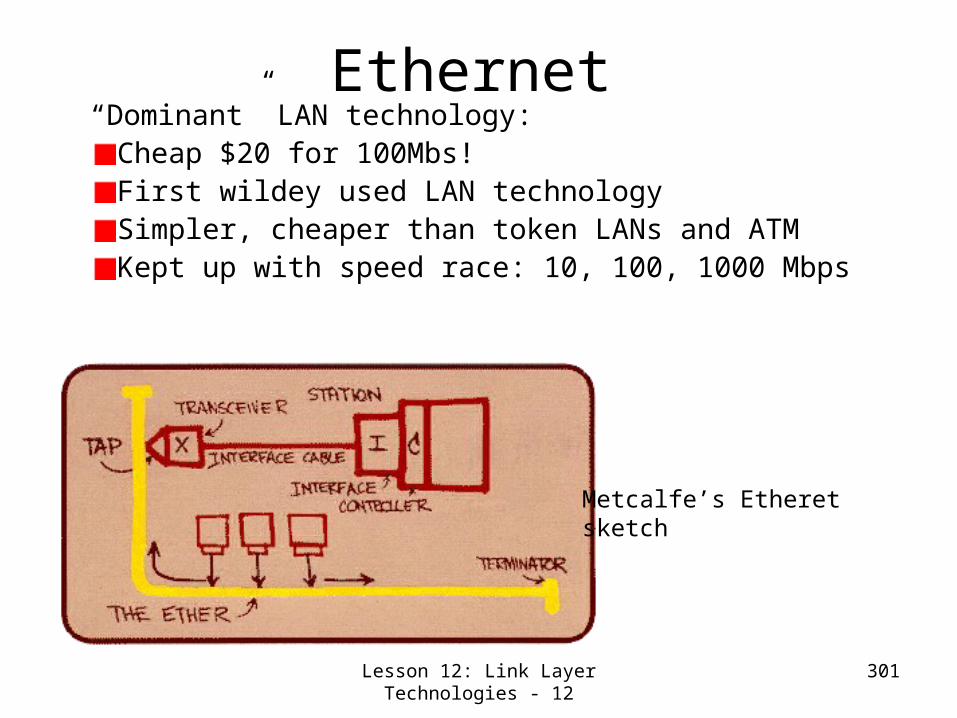
Lesson 12: Link Layer Technologies - 12
301
Ethernet“Dominant” LAN technology:
Cheap $20 for 100Mbs!First wildey used LAN technologySimpler, cheaper than token LANs and ATMKept up with speed race: 10, 100, 1000 Mbps
Metcalfe’s Etheretsketch

Lesson 12: Link Layer Technologies - 13
302
Ethernet Frame StructureSending adapter encapsulates IP datagram (or other
network layer protocol packet) in Ethernet frame
Preamble: 7 bytes with pattern 10101010 followed by one byte with pattern 10101011 Used to synchronize receiver, sender clock ratesLast two 11’s of the 8th for alerting about something important to come.

Lesson 12: Link Layer Technologies - 14
303
Ethernet Frame Structure (Continued)
Addresses: 6 bytes, frame is received by all adapters on a LAN and dropped if address does not matchType: indicates the higher layer protocol, mostly IP but others may be supported such as Novell IPX and AppleTalk)CRC: checked at receiver, if error is detected, the frame is simply dropped
46-1500 bytes
6 bytes 6 bytes 4 bytes2 bytes8 bytes

Lesson 12: Link Layer Technologies - 15
304
Ethernet: CSMA/CD Algorithm
A: sense channel, if idle then {
transmit and monitor the channel; If detect another transmission then { abort and send jam signal;
update # collisions; delay as required by exponential backoff algorithm; goto A}
else {done with the frame; set collisions to zero}
}
else {wait until ongoing transmission is over and goto A}
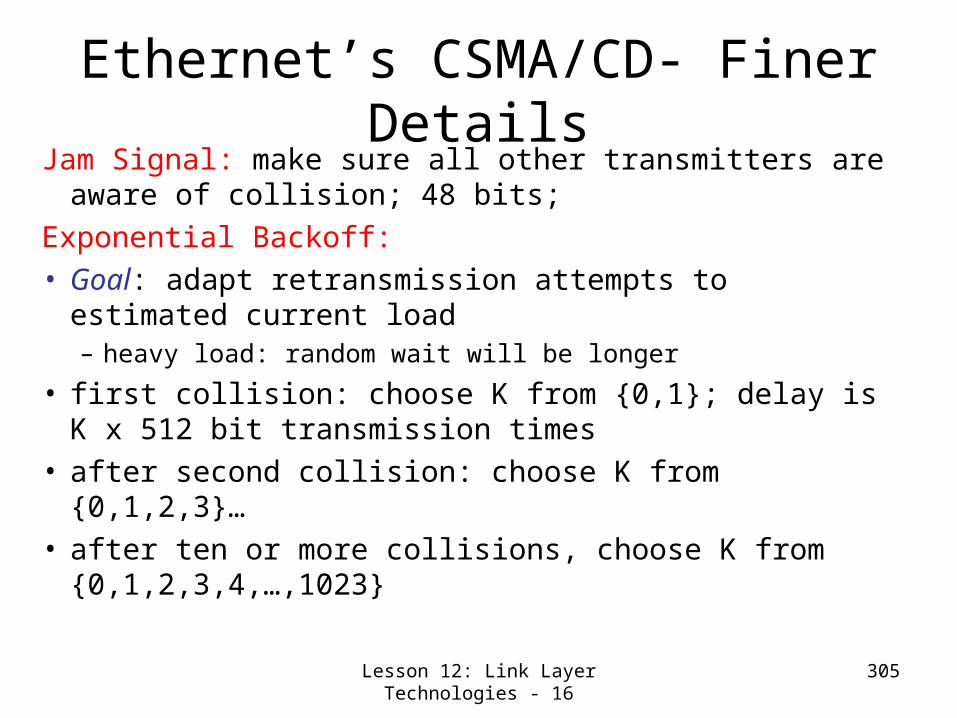
Lesson 12: Link Layer Technologies - 16
305
Ethernet’s CSMA/CD- Finer Details
Jam Signal: make sure all other transmitters are aware of collision; 48 bits;
Exponential Backoff: • Goal: adapt retransmission attempts to estimated
current load– heavy load: random wait will be longer
• first collision: choose K from {0,1}; delay is K x 512 bit transmission times
• after second collision: choose K from {0,1,2,3}…• after ten or more collisions, choose K from
{0,1,2,3,4,…,1023}

Lesson 12: Link Layer Technologies - 17
306
Ethernet Technologies: 10Base2

Lesson 12: Link Layer Technologies - 18
307
10BaseT and 100BaseT• 10/100 Mbps rate; latter called “fast
ethernet”• T stands for Twisted Pair• Hub to which nodes are connected by
twisted pair, thus “star topology”• CSMA/CD implemented at hub

Lesson 12: Link Layer Technologies - 19
308
More on10BaseT and 100BaseT
Max distance from node to Hub is 100 metersHub can disconnect “jabbering adapterHub can gather monitoring information, statistics for display to LAN administrators
Lesson 12: Link Layer Technologies - 20
309
Gbit Ethernet
use standard Ethernet frame format
allows for point-to-point links and shared broadcast channels
in shared mode, CSMA/CD is used; short distances between nodes to be efficient
uses hubs, called here “Buffered Distributors”
Full-Duplex at 1 Gbps for point-to-point links
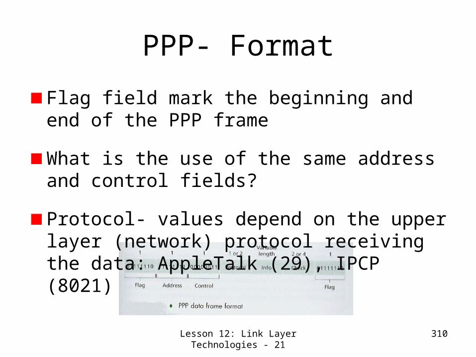
Lesson 12: Link Layer Technologies - 21
310
PPP- Format
Flag field mark the beginning and end of the PPP frame
What is the use of the same address and control fields?
Protocol- values depend on the upper layer (network) protocol receiving the data: AppleTalk (29), IPCP (8021)

Lesson 12: Link Layer Technologies - 22
311
PPP- Format- How differentiate Data and Control Info in the
Header? Answer: A technique called byte stuffing. An
escape byte 01111101 precedes the flags byte appearing as data. What about escape byte itself?

Lesson 12: Link Layer Technologies - 23
312
PPP- State Model PPP’s Link Control Protocol (LCP) manages the states.
Configure-request frame (a PPP Frame with protocol set to LCP value- Co21) and configure-ack/configure-nak/ configure-reject responses received.
Physical layer presence indicated by carrier detection or admin action
Terminate request and ACK exchange

Lesson 12: Link Layer Technologies - 24
313
ATMAAL1- Constant bit rate services AAL2- Variable bit rate (e.g. video) services AAL5- IP Services
AAL (ATM Adaptation Layer)- Performs error detection; Equivalent to Transport layer as it is responsible for segmentation & Reassembly.
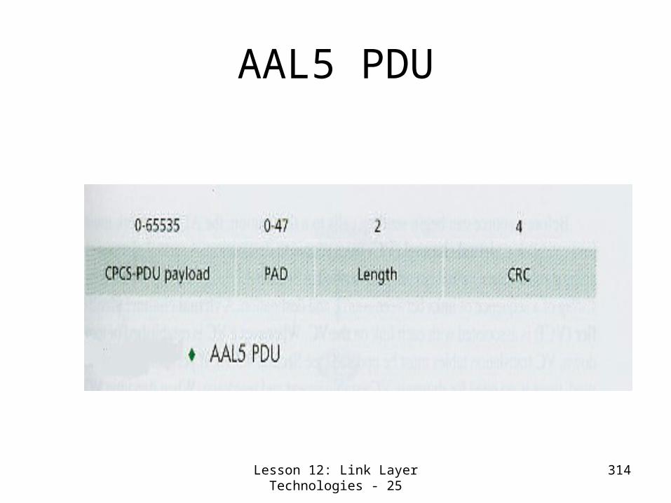
Lesson 12: Link Layer Technologies - 25
314
AAL5 PDU

Lesson 12: Link Layer Technologies - 26
315
ATM Cell Header VCI- Virtual circuit identifier
PT- payload type
CLP- Cell Priority Bit
HEC- Header Error Control
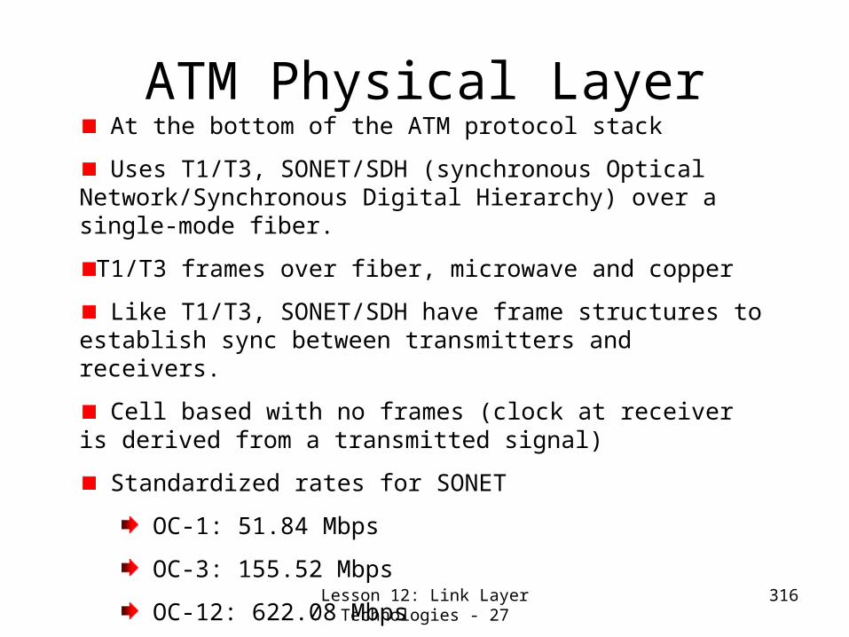
Lesson 12: Link Layer Technologies - 27
316
ATM Physical Layer At the bottom of the ATM protocol stack
Uses T1/T3, SONET/SDH (synchronous Optical Network/Synchronous Digital Hierarchy) over a single-mode fiber.
T1/T3 frames over fiber, microwave and copper
Like T1/T3, SONET/SDH have frame structures to establish sync between transmitters and receivers.
Cell based with no frames (clock at receiver is derived from a transmitted signal)
Standardized rates for SONET
OC-1: 51.84 Mbps
OC-3: 155.52 Mbps
OC-12: 622.08 Mbps
OC-48: 2.5 Gbps

Lesson 12: Link Layer Technologies - 28
317
Wi-Fi: 802.11 Wireless LANs Building Block of Wi-Fi
LAN architecture is Basic Service Set (BSS) containing
a base station, known as access point (AP)
One or more wireless stations
WI-FI Uses CSMA/CA
LANs that deploy APs are called Infrastructure Wireless LANs
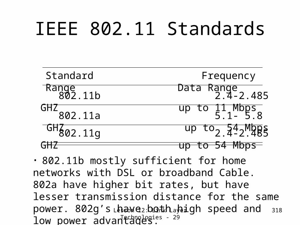
Lesson 12: Link Layer Technologies - 29
318
IEEE 802.11 Standards
802.11b 2.4-2.485 GHZ up to 11 Mbps
Standard Frequency Range Data Range
802.11a 5.1- 5.8 GHZ up to 54 Mbps 802.11g 2.4-2.485 GHZ up to 54 Mbps
• 802.11b mostly sufficient for home networks with DSL or broadband Cable. 802a have higher bit rates, but have lesser transmission distance for the same power. 802g’s have both high speed and low power advantages.

Lesson 12: Link Layer Technologies -30
319
How Wi-Fi works Once AP is installed, it is given 1 or 2
word Service Set Identifier (SSID). It is also given channel numbers- 85 MHz in 802.11b, for example, divided into 11 channels.
As per wifi standard, AP periodically transmits beacon frames with its SSID and MAC Address
Wireless station tries to access an AP using 802.11 association protocol.
When channel is sensed idle, a station (AP or other station) transmits frame after a time called Distributed Inter-Frame Space (DIFS)
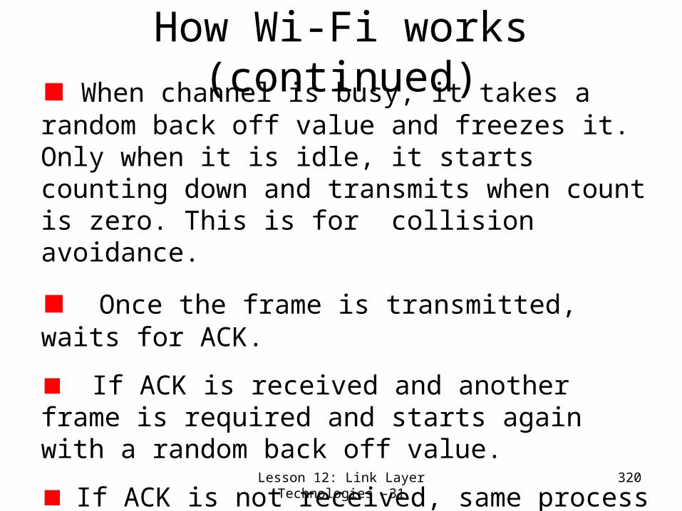
Lesson 12: Link Layer Technologies -31
320
How Wi-Fi works (continued) When channel is busy, it takes a random
back off value and freezes it. Only when it is idle, it starts counting down and transmits when count is zero. This is for collision avoidance.
Once the frame is transmitted, waits for ACK.
If ACK is received and another frame is required and starts again with a random back off value.
If ACK is not received, same process is repeated with a larger back-off value.
Collision is avoided for large frames by Request to Send (RTS) and Clear To Send (CTS) protocol message exchanges before data transmission and ACK.

Lesson 12: Link Layer Technologies - 32
321
Lesson 12: Link Layer Technologies-Summary/Follow-
upWe studied the following link layer technologies and their implementation
Current Multiple Access MAC (Medium Access Control) Protocols-
CSMA/CDChannel Partitioning“Taking Turns” type – Token Ring
Ethernet Hubs, Bridges and SwitchesPPPATMIEEE 802.11 LANs
Next class, we take up Physical Layer

322
Lesson 13: Introduction to Physical Layer

Lesson 13: Introduction to Physical Layer -1
323
Lesson 13: Introduction to Physical Layer
-Preview/ObjectivesWe study physical layer functionality and 3 types of transmission
Simplex Half DuplexFull Duplex
Signals and their propertiesRelation between bandwidth and data rate
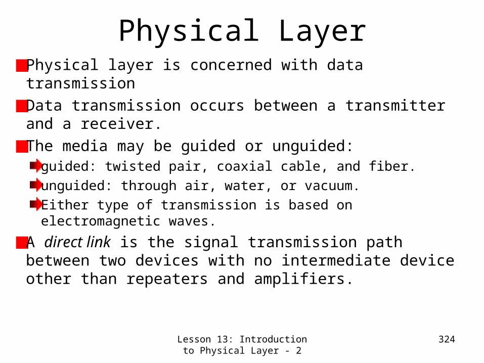
Lesson 13: Introduction to Physical Layer - 2
324
Physical LayerPhysical layer is concerned with data transmissionData transmission occurs between a transmitter and a receiver.The media may be guided or unguided:
guided: twisted pair, coaxial cable, and fiber.unguided: through air, water, or vacuum. Either type of transmission is based on electromagnetic waves.
A direct link is the signal transmission path between two devices with no intermediate device other than repeaters and amplifiers.

Lesson 13: Introduction to Physical Layer - 3
325
A guided medium is point-to-point if it provides a direct link between two devices;the medium is shared by only those two devices;
In a multi-point configuration, more than two devices share the transmission medium.We distinguish 3 forms of transmission:
Simplex Half DuplexFull Duplex
Data Transmission- Some Terminology

Lesson 13: Introduction to Physical Layer - 4
326
Transmission in only one direction; one station is the transmitter, the other the receiver. Examples:
One-Way StreetKeyboard-Computer connectionComputer-Monitor connectionTV BroadcastCan you think of other simplex examples?
Simplex Transmission

Lesson 13: Introduction to Physical Layer - 5
327
Half Duplex: Transmission in both directions possible, but NOT at the same time. Here, the attached stations are both, sender and receiver. Examples:
One-Lane Road with access control lights. While cars go in one directions, cars going the opposite way must wait.Walkie-TalkiesCB-RadiosTraditional Ethernet (Coax or 10baseT)
Half-Duplex Transmission

Lesson 13: Introduction to Physical Layer - 6
328
Transmission in both directions simultaneously. Both stations can send and receive at the same time. Examples:
Regular 2-way streetFull-Duplex repeated Ethernet (Gbit Ethernet)
Full Duplex transmission can be accomplished in two ways:
Separated physical transmission media Divided channel capacity and separation of signals in different directions.
Full Duplex Transmission
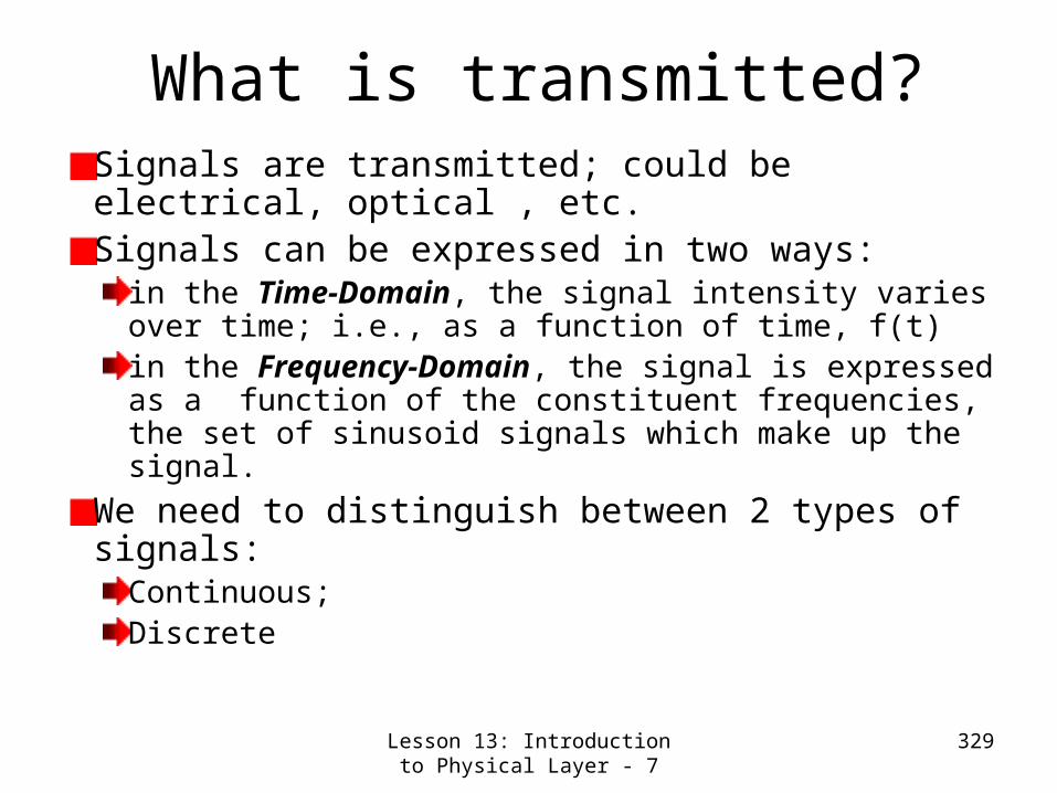
Lesson 13: Introduction to Physical Layer - 7
329
What is transmitted?Signals are transmitted; could be electrical, optical , etc.Signals can be expressed in two ways:
in the Time-Domain, the signal intensity varies over time; i.e., as a function of time, f(t)in the Frequency-Domain, the signal is expressed as a function of the constituent frequencies, the set of sinusoid signals which make up the signal.
We need to distinguish between 2 types of signals:
Continuous;Discrete

Lesson 13: Introduction to Physical Layer - 8
330
A continuous signal is one in which the signal intensity varies in a smooth fashion over time. There are no breaks (poles) or discontinuities.A discrete signal is one in which the signal intensity maintains a constant level for some period of time and then changes to another constant level.Note: A discrete signal may consist of more than just 2 constant levels; i.e., discrete does not mean binary!
Continuous and Discrete Signals

Lesson 13: Introduction to Physical Layer - 9
331
The simplest sort of signal is a periodic signal.
Here, T is said to be the period. T is the smallest value that satisfies the equation.
Definition: a signal s(t) is periodic if and only if
ttsTts )()(
Periodic Signal

Lesson 13: Introduction to Physical Layer - 10
332
The sine wave is the fundamental continuous signal. We can represent the sine wave by 3 parameters:
Amplitude (A)Frequency (f)Phase ()
)ftsin(2As(t)
Sinusoid- The Fundamental
Continuous Signal

Lesson 13: Introduction to Physical Layer - 11
333
Amplitude (A): is the peak value or strength of the signal over time. (in Volts, Watts, etc.)Frequency (f): is the rate (in cycles per second, or Hertz (Hz)) at which the signal repeats.
The period T can be computed as T=1/f. T is the amount of time taken for one repetition.
Phase (): is the measure of the relative position in time within a single period of the signal.
Amplitude, Frequency and Phase

Lesson 13: Introduction to Physical Layer - 12
334
The Wavelength () of a signal is the distance occupied by a single cycle (or period). In other words, it is the distance between to points of corresponding phase of two consecutive cycles.
Here, v represents the velocity of the signal.
vT
Wavelength of a Signal
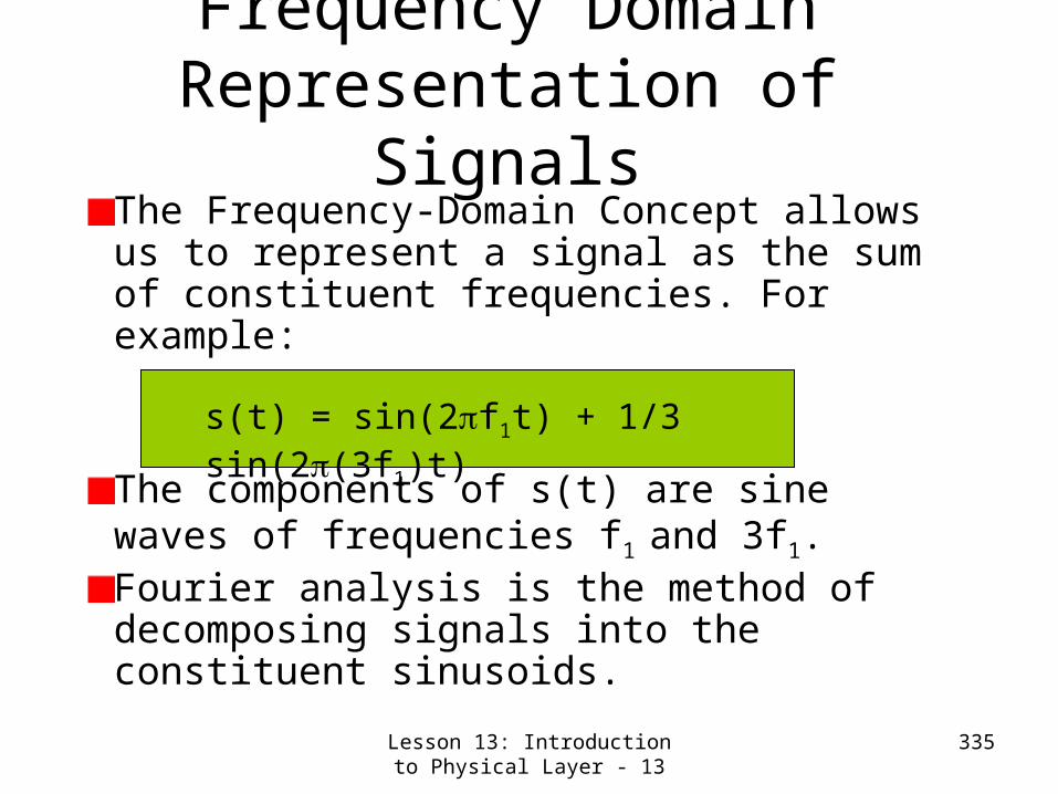
Lesson 13: Introduction to Physical Layer - 13
335
The Frequency-Domain Concept allows us to represent a signal as the sum of constituent frequencies. For example:
The components of s(t) are sine waves of frequencies f1 and 3f1.Fourier analysis is the method of decomposing signals into the constituent sinusoids.
s(t) = sin(2f1t) + 1/3 sin(2(3f1)t)
Frequency Domain Representation of
Signals

Lesson 13: Introduction to Physical Layer - 14
336
When all of the frequency components are integer multiples of one frequency f1, f1 is called the fundamental frequency.
The period of the total signal is equal to the period of the fundamental frequency.The spectrum of a signal is the range of frequencies that it contains. In our example, the spectrum extends from f1 to 3 f1.
Frequency Domain Analysis

Lesson 13: Introduction to Physical Layer - 15
337
BandwidthPhysical property of the transmission mediumDepends on length, thickness, construction, etc.Range of frequencies transmitted without being strongly attenuatedIn our example, the bandwidth required to send the signal without distortion is 3f1- f1 = 2f1.
Note that most of the energy in the signal is contained in a relative narrow band of frequencies. This is referred to as the effective bandwidth required. In this case, a medium with lower bandwidth can transmit this signal with tolerable distortion.

Lesson 13: Introduction to Physical Layer - 16
338
Fourier Analysis- An Overview
Any reasonably behaved periodic signal can be expressed as a sum (possibly infinite) of sines and cosines as follows:
Sine and cosine term pair for a value of n is called nth harmonic.Root Mean Square (RMS) amplitude √an
2+bn2
indicates the significance of the nth harmonic.
s(t)=c/2 + Σn=1 to
∞ansin(2nft)
+ Σn=1 to
∞bncos(2nft)

Lesson 13: Introduction to Physical Layer - 17
339
Relation between Data Rate and Bandwidth
At b bits/sec, time required to send 8-bits = 8/b sec. Freq. of 1st harmonic will be b/8 Hz. How many harmonica pass through a voice grade line with 3000 Hz cut-off?

Lesson 13: Introduction to Physical Layer -18
340
Lesson 13: Introduction to Physical Layer –Summary and
Follow-upWe studied physical layer functionality and 3 types of transmission
Simplex Half DuplexFull Duplex
We studied Signals and their properties (particularly Fourier Analysis)Relation between bandwidth and data rateNext class, we study about wireless access technologies.

341
Lesson 14: Physical Layer (Wireless Access)
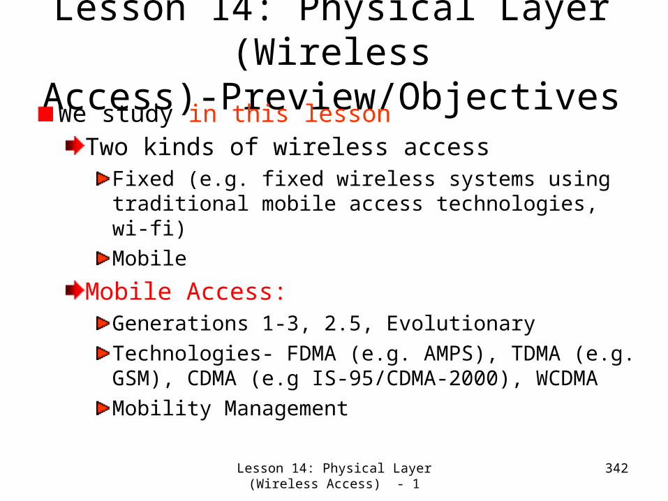
Lesson 14: Physical Layer (Wireless Access) - 1
342
Lesson 14: Physical Layer (Wireless
Access)-Preview/ObjectivesWe study in this lessonTwo kinds of wireless access
Fixed (e.g. fixed wireless systems using traditional mobile access technologies, wi-fi)Mobile
Mobile Access:Generations 1-3, 2.5, EvolutionaryTechnologies- FDMA (e.g. AMPS), TDMA (e.g. GSM), CDMA (e.g IS-95/CDMA-2000), WCDMAMobility Management

Lesson 14: Physical Layer (Wireless Access) - 2
343
How Wireless Systems Work?• Depending upon in which cell
mobile is, it will be able to access a particular base station.
• Call will be se up via a Base Station controller (BSC) and a Mobile Switching Center (MSC) after a lot of call processing (control or signaling messages) back and forth.
• Phone could be stationary (fixed) or mobile- but in case of mobile phones a technique called hand-over/hand-off is used.
A B C D
BSC-X
MSC or PDSN/GGSN
BSC-Y
RNC in UMTS jargon

Lesson 14: Physical Layer (Wireless Access) - 3
344
Multiple Access
Each pair of users enjoy a dedicated, private circuit through the transmission medium (air in case of wireless systems), unaware of the existence of other users.

Lesson 14: Physical Layer (Wireless Access) - 4
345
Generations of Wireless Technologies• 1st Generation Mobile Phones (Analog Voice)
– Push to Talk Systems (e.g. CB radios, police radios) in late 1950s
– IMTS (Improved Mobile Telephone Systems) 1960s– AMPS (Advanced Mobile Phone Systems) 1982 by Bell
Labs
• 2nd Generation (Digital Voice)– D-AMPS, GSM and CDMA (IS-95)
• 3rd Generation– 1XRTT, CDMA-200 and UMTS (Universal Mobile
Telecommunications System) based on W-CDMA.
• Beyond 3g (B3g)- Evolutionary (1xEVDV, 1xEVDO, etc.)
• 2.5 G – Enhanced Data Rates for GSM (Edge) and GPRS (General
Packet Radio Services)

Lesson 14: Physical Layer (Wireless Access) - 5
346
CDMA-Spread Spectrum• Slow varying (low frequency) data signal
is spread over a large spectrum using a fast (high frequency signal
• CDMA spreading principle- Anything we can do , we can undo.

Lesson 14: Physical Layer (Wireless Access) - 6
347
How do you do & Undo?
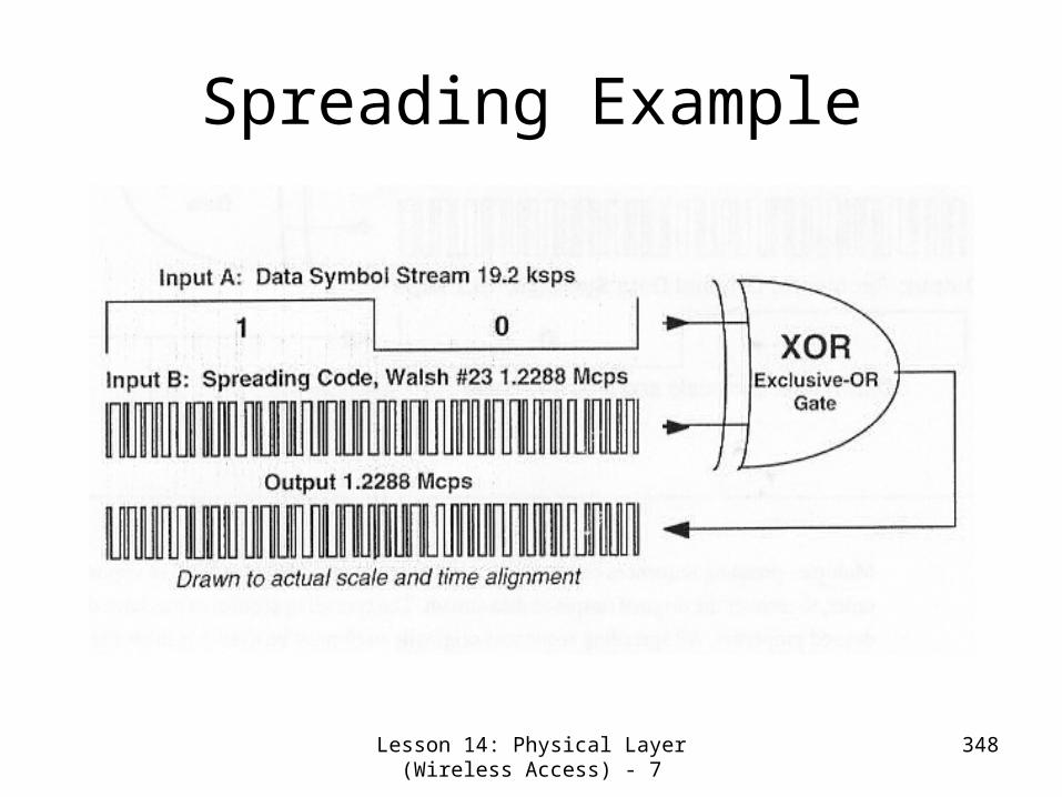
Lesson 14: Physical Layer (Wireless Access) - 7
348
Spreading Example

Lesson 14: Physical Layer (Wireless Access) - 8
349
De-spreading (Recovery of Previously Spread Data) for the
same Example

Lesson 14: Physical Layer (Wireless Access) - 9
350
How do you handle mixture of signals from multiple users?
• Use orthogonal signals (e.g. Walsh codes) for spreading.
• Two signals are orthogonal if their XOR sum has equal number of 1’s and 0’s (e.g. 111111 and 101010)

Lesson 14: Physical Layer (Wireless Access) - 10
351
Mobility Management
• Hand-off/Hand-over• Two types
– Soft-handoff (Continuous connection with two base stations and seamless transfer)
– Hard-handoff (mobile stops transmitting, adjusts its parameters and restarts)• Intersystem (control is passed to a new
MSC)• Intra-system

Lesson 14: Physical Layer (Wireless Access) - 11
352
Lesson 14: Physical Layer (Wireless
Access)-Summary/Follow-upWe studied in this lessonTwo kinds of wireless access
Fixed (e.g. fixed wireless systems using traditional mobile access technologies, wi-fi)Mobile
Mobile Access:Generations 1-3Technologies- FDMA (e.g. AMPS), TDMA (e.g. GSM), CDMA (e.g IS-95/CDMA-2000), WCDMAMobility Management

353
Lesson 15: Introduction to Network Security

Lesson 15: Introduction to Network Security - 1
354
Lesson 15: Introduction Network Security-Preview/Objectives
We study in this lessonWhat is security? What all it entails?
CryptographyAuthenticationMessage Integrity
Types of Keys for encryption, their distribution and certificationFamous Public Key Algorithm (RSA)

Lesson 15: Introduction to Network Security - 2
355
Friends and enemies: Alice, Bob, Trudy
Well-known in network security worldBob, Alice (close friends) want to communicate “securely”Trudy, the “intruder” may intercept, delete, add messages
Figure 7.1 goes here

Lesson 15: Introduction to Network Security - 3
356
What is network security?
Secrecy: only sender, intended receiver should “understand” message contents
sender encrypts messagereceiver decrypts message
Authentication: sender, receiver want to confirm identity of each other Message Integrity: sender, receiver want to ensure message not altered (in transit, or afterwards) without detection

Lesson 15: Introduction to Network Security - 4
357
Internet security threats I- Packet Sniffing
Packet sniffing is possible because the media is broadcast typepromiscuous NIC reads all packets passing byany one can read all unencrypted data (e.g. passwords) e.g.: C sniffs B’s packets
A
B
C
src:B dest:A payload

Lesson 15: Introduction to Network Security - 5
358
Internet security threats II- IP SpoofingIP Spoofing (e.g. C pretending to be B) is done by:
Generation of “raw” IP packets directly from application, putting any value into IP source address field such that
receiver can’t tell if source is spoofed
More generic name for this kind of attack- Sybil attack where even bogus messages can be introduced in the network.
A
B
C
src:B dest:A payload

Lesson 15: Introduction to Network Security - 6
359
Internet security threats III: Denial of Service Attack
This attack is done by– A flood of maliciously generated packets that “swamp” receiver– Distributed DOS (DDOS): multiple coordinated sources that
swamp receiver e.g. C and remote host SYN-attack A
A
B
C
SYN
SYNSYNSYN
SYN
SYN
SYN
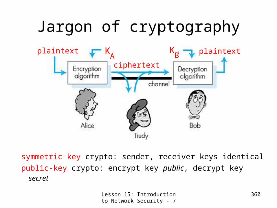
Lesson 15: Introduction to Network Security - 7
360
Jargon of cryptography
symmetric key crypto: sender, receiver keys identical
public-key crypto: encrypt key public, decrypt key secret
Figure 7.3 goes here
plaintext plaintext
ciphertext
KA
KB

Lesson 15: Introduction to Network Security - 8
361
Symmetric key cryptographySubstitution cipher: substituting one thing for
anothermonoalphabetic cipher: substitute one letter for another
plaintext: abcdefghijklmnopqrstuvwxyz
ciphertext: mnbvcxzasdfghjklpoiuytrewq
Plaintext: bob. i love you. aliceciphertext: nkn. s gktc wky. mgsbc
E.g.:
Q: How hard to break this simple cipher?:brute force (how hard?)other?

Lesson 15: Introduction to Network Security - 9
362
Symmetric key crypto: DESDES: Data Encryption Standard
US encryption standard [NIST 1993]56-bit symmetric key, 64 bit plaintext inputHow secure is DES?
DES Challenge: 56-bit-key-encrypted phrase (“Strong cryptography makes the world a safer place”) decrypted (brute force) in 4 monthsno known “backdoor” decryption approach
making DES more secureuse three keys sequentially (3-DES) on each datumuse cipher-block chaining

Lesson 15: Introduction to Network Security - 10
363
Symmetric key
crypto: DES
initial permutation 16 identical “rounds” of
function application, each using different 48 bits of key
final permutation
DES operation

Lesson 15: Introduction to Network Security - 11
364
Public Key Cryptographysymmetric key
cryptorequires sender, receiver know shared secret keyQ: how to agree on key in first place (particularly if never “met”)?
public key cryptographyradically different approach [Diffie-Hellman76, RSA78]sender, receiver do not share secret keyencryption key public (known to all) decryption key private (known only to receiver)

Lesson 15: Introduction to Network Security - 12
365
Public key cryptography
Figure 7.7 goes here

Lesson 15: Introduction to Network Security - 13
366
Public key encryption algorithms
need d ( ) and e ( ) such that
d (e (m)) = m BB
B B
need private and public keys
for d ( ) and e ( ), respectively
BB
Two inter-related requirements:
1
2
RSA: Rivest, Shamir, Adelson algorithm

Lesson 15: Introduction to Network Security - 14
367
RSA: Encryption, decryption0. Given (n,e) and (n,d) as computed above
1. To encrypt bit pattern, m, compute
c = m mod n
e (i.e., remainder when m is divided by n)e
2. To decrypt received bit pattern, c, compute
m = c mod n
d (i.e., remainder when c is divided by n)d
m = (m mod n)
e mod n
dMagichappens!

Lesson 15: Introduction to Network Security - 15
368
RSA: Choosing keys1. Choose two large prime numbers p, q. (e.g., 1024 bits each)
2. Compute n = pq, z = (p-1)(q-1)
3. Choose e (with e<n) that has no common factors with z. (e, z are “relatively prime”).
4. Choose d such that ed-1 is exactly divisible by z. (in other words: ed mod z = 1 ).
5. Public key is (n,e). Private key is (n,d).

Lesson 15: Introduction to Network Security - 16
369
RSA example:Bob chooses p=5, q=7. Then n=35, z=24.
e=5 (so e, z relatively prime).d=29 (so ed-1 exactly divisible by z.
m me c = m mod ne
12 248832 17
c m = c mod nd
17 481968572106750915091411825223072000 12
cd
encrypt:
decrypt:

Lesson 15: Introduction to Network Security - 17
370
RSA: How does it work?m = (m mod
n)
e mod n
d
1. Fermat’s little theorem :(x p-1 mod p = 1), when p is prime and x is prime to p.
2. Chinese Reminder Theorem : If a = b mod p and a=b mod q where p and q are relatively prime, a=b mod pq.
To prove: , we use two theorems:
(me)d =med= med-1.m= mh(p-1)(q-1).m = 1h(q-1).m (mod p) = m (mod p)(me)d =med= med-1.m= mh(p-1)(q-1).m = 1h(p-1).m (mod q) = m (mod q) Hence, (me)d = m (mod pq) by Chinese Reminder TheoremIn the above, h is an integer . Since ed-1 is divisible by z=(p-1)(q-1), ed-1 = hz =h(p-1)(q-1).

Lesson 15: Introduction to Network Security - 18
371
RSA: Is it the end of Public Key Cryptography?
No. Recently, another algorithm called Elliptic Curve Cryptography is getting popular as it is even more difficult to break.
Lesson 15: Introduction to Network Security - 19
372
Lesson 15: Introduction to Network
Security-Summary/Follow-upWe studied in this lessonWhat is security? What all it entails?
CryptographyAuthenticationMessage Integrity
Types of Keys for encryption, their distribution and certificationFamous Public Key Algorithm (RSA)
In the next class, we take up other security issues (e.g. authentication) and some applications.

373
Lesson 16: Network Security
(Continued)

Lesson 16: Network Security (Continued) - 1
374
Lesson 16: Network Security (Continued)-Preview/Objectives
We study in this lessonA more detailed view of the following security features:
AuthenticationMessage IntegrityKey distribution and certification
Security in practice:Application layer: secure e-mailTransport layer: Internet commerce, SSL, SET Network layer: IP security

Lesson 16: Network Security (Continued) - 2
375
Authentication
Goal: Bob wants Alice to “prove” her identity to him
Protocol ap1.0: Alice says “I am Alice”
Failure scenario??

Lesson 16: Network Security (Continued) - 3
376
Authentication: another try
Protocol ap2.0: Alice says “I am Alice” and sends her IP address along to “prove” it.
Failure scenario??
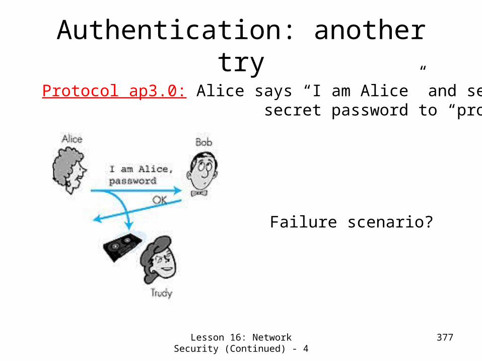
Lesson 16: Network Security (Continued) - 4
377
Authentication: another try
Protocol ap3.0: Alice says “I am Alice” and sends her secret password to “prove” it.
Failure scenario?

Lesson 16: Network Security (Continued) - 5
378
Authentication: yet another try
Protocol ap3.1: Alice says “I am Alice” and sends her encrypted secret password to “prove” it.
Failure scenario?
I am Aliceencrypt(password)

Lesson 16: Network Security (Continued) - 6
379
Authentication: yet another tryGoal: avoid playback attack
Failures, drawbacks?
Figure 7.11 goes here
Nonce: number (R) used only once in a lifetime
ap4.0: to prove Alice “live”, Bob sends Alice nonce, R. Alice
must return R, encrypted with shared secret key

Lesson 16: Network Security (Continued) - 7
380
Figure 7.12 goes here
Authentication: ap5.0
ap4.0 requires shared symmetric key– problem: how do Bob, Alice agree on
key– can we authenticate using public key
techniques?
ap5.0: use nonce, public key cryptography
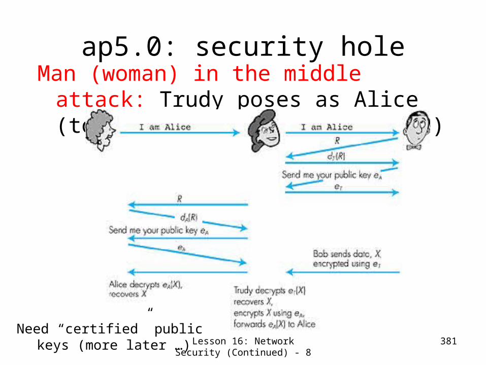
Lesson 16: Network Security (Continued) - 8
381
Figure 7.14 goes here
ap5.0: security holeMan (woman) in the middle attack:
Trudy poses as Alice (to Bob) and as Bob (to Alice)
Need “certified” public keys (more later …)

Lesson 16: Network Security (Continued) - 9
382
Digital Signatures
Cryptographic technique analogous to hand-written signatures.
• Sender (Bob) digitally signs document, establishing he is document owner/creator.
• Verifiable, nonforgeable: recipient (Alice) can verify that Bob, and no one else, signed document.
Simple digital signature for message m:
• Bob encrypts m with his private key dB, creating signed message, dB(m).
• Bob sends m and dB(m) to Alice.

Lesson 16: Network Security (Continued) - 10
383
More on Digital Signatures
• Suppose Alice receives msg m, and digital signature dB(m)
• Alice verifies m signed by Bob by applying Bob’s public key eB to dB(m) then checks eB(dB(m) ) = m.
• If eB(dB(m) ) = m, whoever signed m must have used Bob’s private key.
Alice thus verifies that:– Bob signed m.– No one else signed
m.– Bob signed m and
not m’.Non-repudiation:
– Alice can take m, and signature dB(m) to court and prove that Bob signed m.

Lesson 16: Network Security (Continued) - 11
384
Message Digests
Computationally expensive to public-key-encrypt long messages
Goal: fixed-length,easy to compute digital signature, “fingerprint”
• apply hash function H to m, get fixed size message digest, H(m).
Hash function properties:• Many-to-1• Produces fixed-size msg
digest (fingerprint)• Given message digest x,
computationally infeasible to find m such that x = H(m)
• computationally infeasible to find any two messages m and m’ such that H(m) = H(m’).

Lesson 16: Network Security (Continued) - 12
385
Digital signature = Signed message digest
Bob sends digitally signed message:
Alice verifies signature and integrity of digitally signed message:

Lesson 16: Network Security (Continued) - 13
386
Hash Function Algorithms• Internet
checksum would make a poor message digest.– Too easy to find
two messages with same checksum.
• MD5 hash function widely used. – Computes 128-bit
message digest in 4-step process.
– arbitrary 128-bit string x, appears difficult to construct msg m whose MD5 hash is equal to x.
• SHA-1 is also used.– US standard– 160-bit message digest
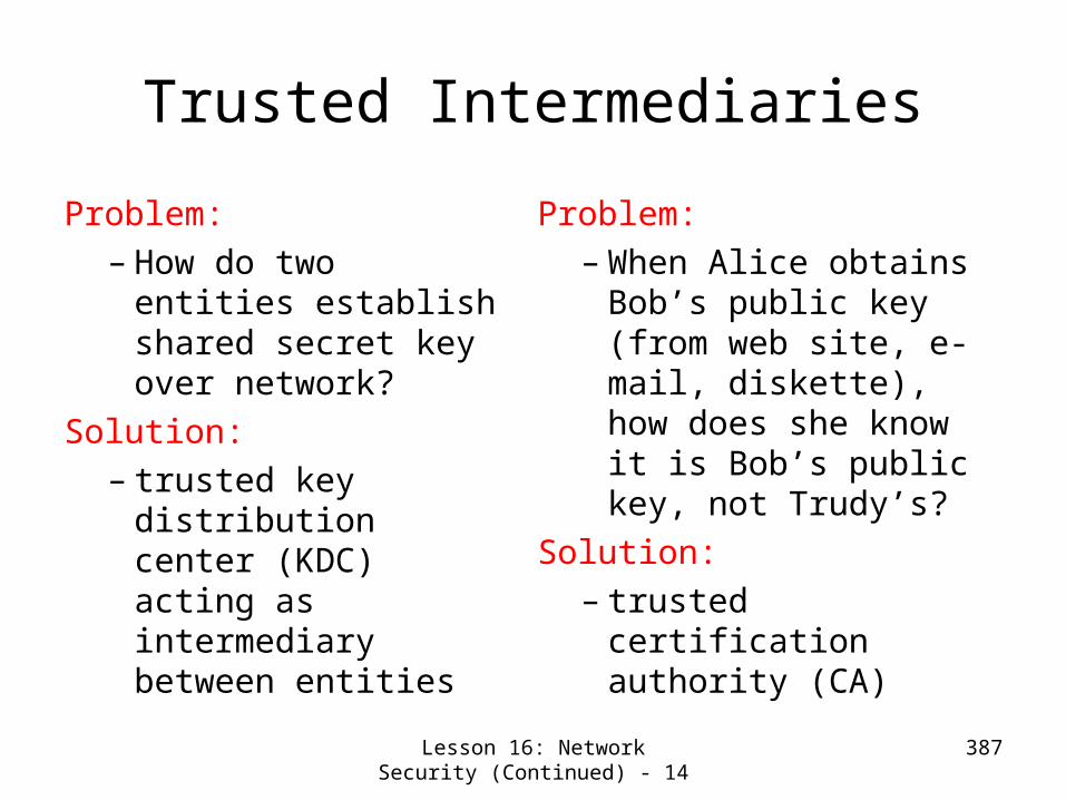
Lesson 16: Network Security (Continued) - 14
387
Trusted Intermediaries
Problem:– How do two entities
establish shared secret key over network?
Solution:– trusted key
distribution center (KDC) acting as intermediary between entities
Problem:– When Alice obtains
Bob’s public key (from web site, e-mail, diskette), how does she know it is Bob’s public key, not Trudy’s?
Solution:– trusted certification
authority (CA)

Lesson 16: Network Security (Continued) - 15
388
Key Distribution Center (KDC)
• Alice,Bob need shared symmetric key.
• KDC: server shares different secret key with each registered user.
• Alice, Bob know own symmetric keys, KA-
KDC KB-KDC , for communicating with KDC.
• Alice communicates with KDC, gets session key R1, and KB-
KDC(A,R1)
• Alice sends Bob KB-KDC(A,R1), Bob extracts R1
• Alice, Bob now share the symmetric key R1.

Lesson 16: Network Security (Continued) - 16
389
Certification Authorities• Certification authority
(CA) binds public key to particular entity.
• Entity (person, router, etc.) can register its public key with CA.– Entity provides “proof
of identity” to CA. – CA creates certificate
binding entity to public key.
– Certificate digitally signed by CA.
• When Alice wants Bob’s public key:
• gets Bob’s certificate (Bob or elsewhere).
• Apply CA’s public key to Bob’s certificate, get Bob’s public key

Lesson 16: Network Security (Continued) - 17
390
Secure e-mail
• generates random symmetric private key, KS.• encrypts message with KS
• also encrypts KS with Bob’s public key.• sends both KS(m) and eB(KS) to Bob.
• Alice wants to send secret e-mail message, m, to Bob.

Lesson 16: Network Security (Continued) - 18
391
Secure e-mail (continued)• Alice wants to provide sender authentication message integrity.
• Alice digitally signs message.• sends both message (in the clear) and digital signature.
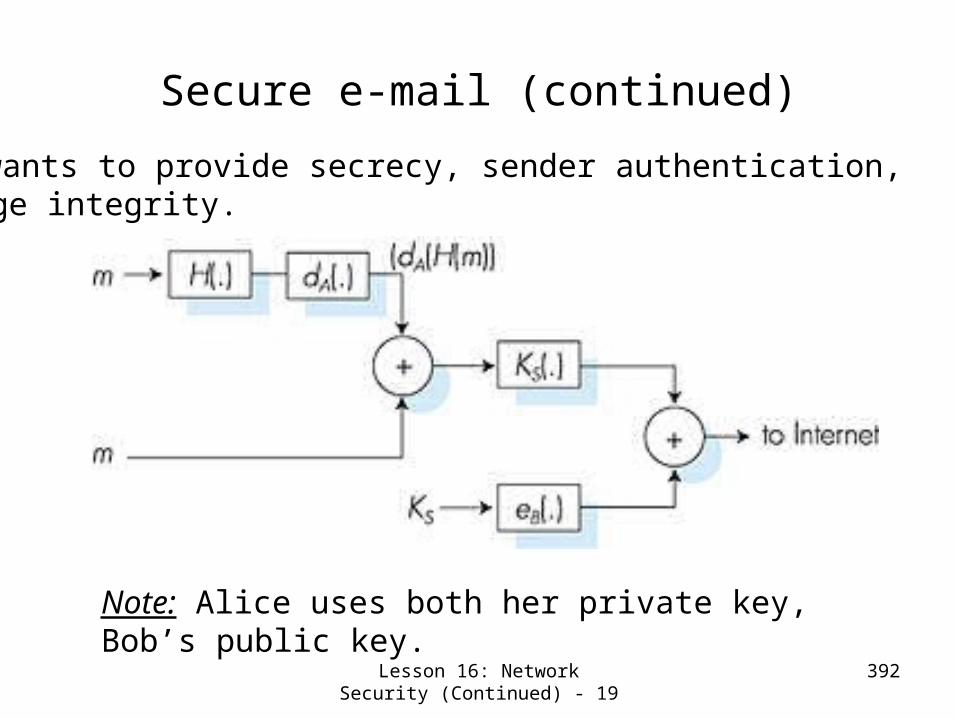
Lesson 16: Network Security (Continued) - 19
392
Secure e-mail (continued)
• Alice wants to provide secrecy, sender authentication, message integrity.
Note: Alice uses both her private key, Bob’s public key.

Lesson 16: Network Security (Continued) - 20
393
Pretty good privacy (PGP)
• Internet e-mail encryption scheme, a de-facto standard.
• Uses symmetric key cryptography, public key cryptography, hash function, and digital signature as described.
• Provides secrecy, sender authentication, integrity.
• Inventor, Phil Zimmerman, was target of 3-year federal investigation.
---BEGIN PGP SIGNED MESSAGE---Hash: SHA1
Bob:My husband is out of town tonight.Passionately yours, Alice
---BEGIN PGP SIGNATURE---Version: PGP 5.0Charset: noconvyhHJRHhGJGhgg/
12EpJ+lo8gE4vB3mqJhFEvZP9t6n7G6m5Gw2
---END PGP SIGNATURE---
A PGP signed message:
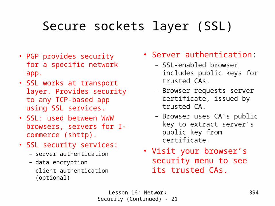
Lesson 16: Network Security (Continued) - 21
394
Secure sockets layer (SSL)
• PGP provides security for a specific network app.
• SSL works at transport layer. Provides security to any TCP-based app using SSL services.
• SSL: used between WWW browsers, servers for I-commerce (shttp).
• SSL security services:– server authentication– data encryption – client authentication
(optional)
• Server authentication:– SSL-enabled browser
includes public keys for trusted CAs.
– Browser requests server certificate, issued by trusted CA.
– Browser uses CA’s public key to extract server’s public key from certificate.
• Visit your browser’s security menu to see its trusted CAs.
Lesson 16: Network Security (Continued) - 22
395
SSL (continued)
Encrypted SSL session:• Browser generates
symmetric session key, encrypts it with server’s public key, sends encrypted key to server.
• Using its private key, server decrypts session key.
• Browser, server agree that future messages will be encrypted.
• All data sent into TCP socket (by client or server) is encrypted with session key.
• SSL: basis of IETF Transport Layer Security (TLS).
• SSL can be used for non-Web applications, e.g., IMAP.
• Client authentication can be done with client certificates.
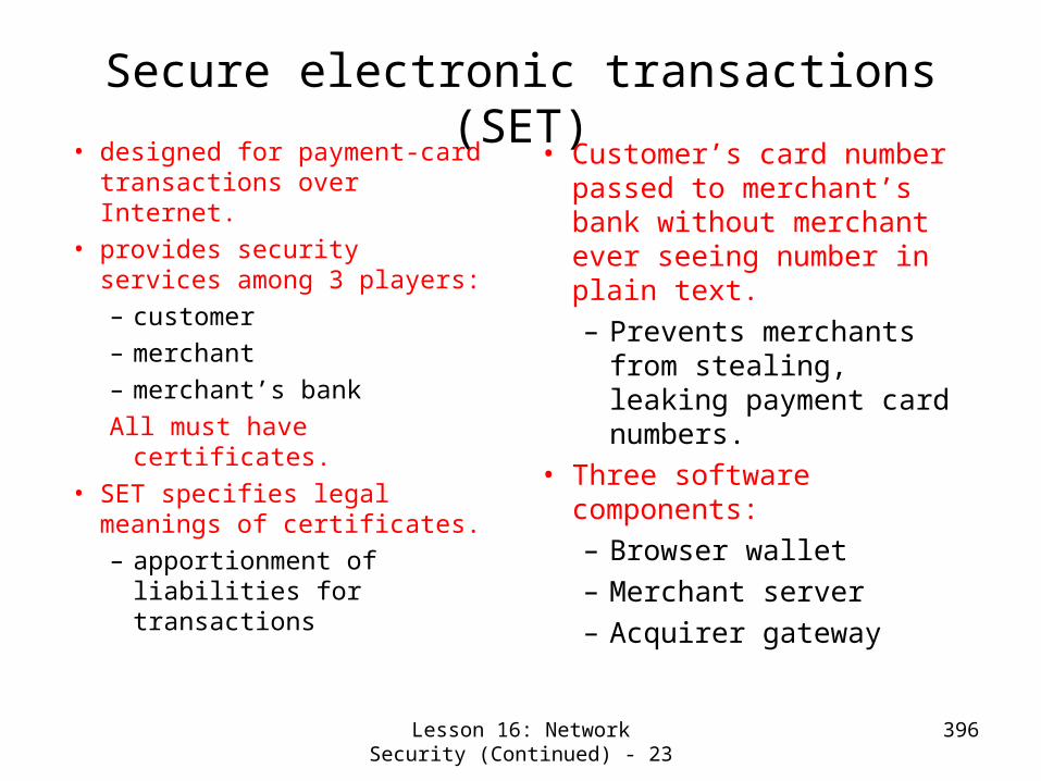
Lesson 16: Network Security (Continued) - 23
396
Secure electronic transactions (SET)• designed for payment-card
transactions over Internet.• provides security services
among 3 players:– customer– merchant– merchant’s bankAll must have certificates.
• SET specifies legal meanings of certificates.– apportionment of
liabilities for transactions
• Customer’s card number passed to merchant’s bank without merchant ever seeing number in plain text.– Prevents merchants
from stealing, leaking payment card numbers.
• Three software components:– Browser wallet– Merchant server– Acquirer gateway

Lesson 16: Network Security (Continued) - 24
397
IPSEC: Network Layer Security• Network-layer secrecy:
– sending host encrypts the data in IP datagram
– TCP and UDP segments; ICMP and SNMP messages.
• Network-layer authentication– destination host can
authenticate source IP address
• Two principle protocols:– authentication header (AH)
protocol– encapsulation security
payload (ESP) protocol
• For both AH and ESP, source, destination handshake:– create network-layer
logical channel called a service agreement (SA)
• Each SA unidirectional.• Uniquely determined by:
– security protocol (AH or ESP)
– source IP address– 32-bit connection ID

Lesson 16: Network Security (Continued) - 25
398
ESP Protocol• Provides secrecy, host
authentication, data integrity.
• Data, ESP trailer encrypted.• Next header field is in ESP
trailer.
• ESP authentication field is similar to AH authentication field.
• Protocol = 50.

Lesson 16: Network Security (Continued) - 26
399
Authentication Header (AH) Protocol• Provides source host
authentication, data integrity, but not secrecy.
• AH header inserted between IP header and IP data field.
• Protocol field = 51.• Intermediate routers
process datagrams as usual.
AH header includes:• connection identifier• authentication data: signed
message digest, calculated over original IP datagram, providing source authentication, data integrity.
• Next header field: specifies type of data (TCP, UDP, ICMP, etc.)

Lesson 16: Network Security (Continued) - 27
400
Lesson 16: Network Security (Continued)-Summary/Follow-up
We studied in this lessonA more detailed view of the following security features:
AuthenticationMessage IntegrityKey distribution and certification
Application of those security features in practice:
Application layer: secure e-mailTransport layer: Internet commerce, SSL, SET Network layer: IP security (IPSec)