Embed Size (px)
Citation preview

Sensing Platforms and Power Consumption Issues
Lecture 2 September 6, 2005
EENG 460a / CPSC 436 / ENAS 960 Networked Embedded Systems &
Sensor Networks
Andreas [email protected]
Office: AKW 212Tel 432-1275
Course Websitehttp://www.eng.yale.edu/enalab/courses/2005f/eeng460a

Today
Course emphasis areas and project discussions – detailed project proposals due Sept 27
Overview of sensing platforms Power consumption issues

Need for Sensing Platforms
Fundamental Problems
Close coupling between fundamental research questions and the physical world
Experimental Systems
In situ data collection
Architectural requirements
Numerous unknown factors and conditions with no prior knowledge• Sensing channels not well characterized - very complex environment dynamics• Power consumption hard to characterize – need to understand battery behaviors and how SW & HW components affect power consumption

Some platforms & applications
Seismic monitoring, personal exploration rover, mobile micro-servers, networked info-mechanical systems, hierarchical wireless sensor networks
[NIMS, UCLA] [Robotics, CMU] [Intel + UCLA]
[CENS, UCLA][Intel + UCLA]
[Slide from V. Ragunanthan]

A Generic Sensor Network Architecture
PROCESSINGSUB-SYSTEM
COMMUNICATIONSUB-SYSTEM
SENSINGSUB-SYSTEM
POWER MGMT.SUB-SYSTEM
ACTUATIONSUB-SYSTEM

Base Case: The Mica Mote(The most popular sensing platform today)
AVR 128, 8-bit MCUDS2401Unique ID
51-PIN I/O Connector
Transmission Power Control
Hardware Accelerators
Radio Transceiver(CC1000 or CC2420)
Power Regulation MAX1678(3V)
Co-processor
External Flash
Digital I/O Analog I/OProgramming
Lines
For more information refer to the TinyOS Website http://www.tinyos.net Crossbow motes at http://www.xbow.com

What is Stargate? A single board, wireless-equipped computing platform
• Developed at Intel Research Leverages advances in computation, communication and storage to facilitate wireless
systems research

System architecture

Computation sub-system PXA255 processor based on the XScale
microarch. • Successor to the StrongARM family
• Variable clock (100 - 400 MHz), less than 500 mW power
• Several sleep modes, rich set of peripherals

UCLA iBadge

Telos: New OEP Mote*
Single board philosophy• Robustness, Ease of use, Lower Cost• Integrated Humidity & Temperature sensor
First platform to use 802.15.4• CC2420 radio, 2.4 GHz, 250 kbps (12x mica2)• 3x RX power consumption of CC1000, 1/3 turn on time• Same TX power as CC1000
Motorola HCS08 processor• Lower power consumption, 1.8V operation,
faster wakeup time• 40 MHz CPU clock, 4K RAM
Package• Integrated onboard antenna +3dBi gain• Removed 51-pin connector• Everything USB & Ethernet based• 2/3 A or 2 AA batteries• Weatherproof packaging
Support in upcoming TinyOS 1.1.3 Release Codesigned by UC Berkeley and Intel Research Available February from Moteiv (moteiv.com)
*D. Culler, UC Berkeley

Wireless DPM: Hierarchical radios
Three vastly different wireless radios supported
Combined to form power-efficient, heterogeneous communication subsystem• Hierarchical device discovery and connection setup scheme leads to up
to 40X savings in discovery power
Technology
Data RateTx
CurrentEnergy per
bitIdle
CurrentStartup
time
Mote 76.8 Kbps 10 mA 430 nJ/bit 7 mA Low
Bluetooth 1 Mbps 45 mA 149 nJ/bit 22 mA Medium
802.11 11 Mbps 300 mA 90 nJ/bit 160 mA High
IEEE 802.11
Bluetooth
Mote
Energy per bit
Startup time
Idle current

Example Platform 1: XYZ Node
Research and education node to do tasks not doable with existing nodes• Need for 32 bit computation for distributed signal processing protocols
o E.g Localization protocol stacks and optimizations• Need to be closer to the Sensors
o Do fast sampling and processing close to the sensors– E.g real-time acceleration or gyro measurements– Acoustic sampling and correlation – need memory, peripherals and
processing to be close to the computation resource – simplifies programming
• Accommodate custom form factors and interfaces for experimenting with mobile computing applications
o Mobility support interfaces (stronger connectors, output for motor contollers)
o Wearable applications – small package• Very low power, long term sleep modes

XYZ’s Architecture

Features• ARM7TDMI• ROM-less (ML675001) 256KB MCP Flash (ML67Q5002) 512KB MCP Flash (ML67Q5003)• 8KB Unified Cache• 32KB RAM • Interrupts 25 + 1 FIQ• I2C (1-ch x master)• DMA (2-ch)• Timers (7 x 16-bit)• WDT (16-bit)• PWM (2 x 16-bit)• UART (2-ch)/ SIO (1-ch) • GPIO (5 x 8-bit) • ADC (4-ch x 10-bit)
• up to 66MHz• -40 ~ +85 C• Package 144 LFBGA 144 QFP
XYZ Computation:The OKI ARM ML675001/67Q5002/67Q5003
[Slide from OKI Semiconductor]

OKI ARM ML675001/67Q5002/67Q5003
ARM7TDMI

XYZ’s Multiple Operational Modes Frequency scaling
6 different operating frequencies. 1.8MHz – 57.6MHz
Radio management 8 discrete transmission power levels. Sleep mode. Turn on/off.
Individual peripherals I/O clock is different than the CPU clock enable/disable internal clock divider.
Sleep modes STANDBY
• Clock oscillation is stopped.• Only an external interrupt can cause CPU to exit this mode.• Wait for clock to stabilize after waking up.
HALT• Clock oscillation is not stopped.• Clock signal is blocked to specific blocks.• Any interrupt (internal or external) can cause the CPU to exit this mode• No need to wait for the clock to stabilize after waking up
Deep Sleep mode
XYZ is turned off! Only the Real Time Clock is operational.
Only the Real Time Clock can wake up the node.
Current drawn: ≈30μΑ

XYZ’s Deep Sleep mode: Supervisor Circuitry
Step 1: Turn on the node.
Step 2: The μC takes control of the Enable pin of the voltage regulator.
Step 3: Turn the power switch to the STBY position.
Step 4: The μC selects the total time that wants to be turned off and programs the DS1337 accordingly, through the 2-wire serial interface.
Step 5: The DS1337 disables the voltage regulator and uses its own crystal to keep the notion of time. The entire sensor node is turned off!
Step 6: The DS1337 enables the voltage regulator after the programmed amount of time has elapsed.
Step 7: The μC takes control of the Enable pin of the voltage regulator
OKI μC
RTC
DS1337
Voltage Regulator
3 x AA batteries
2.5V
3.3V
I2C
WAKEUP
Enable
Interrupt (SQW)
GPIO
INT_1
INT_2
ON
STBY

XYZ: Power Characterization
Frequency Scaling
Current consumption varies from 15.5mA(1.8MHz) to 72mA(57.6MHz) Disabling all the peripherals (except the timers) results to a reduction of 0.5mA (1.8MHz) to 12mA(57.6MHz) Peripherals cause most of the overhead
SOS and Zigbee MAC layer overhead: 2 schedulers 4 hardware timers 1 software timer 20 mA @ maximum frequency
0 10 20 30 40 50 600
10
20
30
40
50
60
70
80
FREQUENCY (MHz)
CU
RR
EN
T (m
A)
CPU CORETOTALRADIOCPU I/Oonly timers enabledall I/O enabled
0 10 20 30 40 50 600
10
20
30
40
50
60
70
80
FREQUENCY (MHz)C
UR
RE
NT
(mA
)
CPU CoreTotal
SOS and Zigbee active
IDLE (SOS and Zigbee loaded)
IDLE (SOS and Zigbee NOT loaded)

Power Mode Transitioning Overheads
Frequency (MHz)
STANDBY HALT
Sleep Wake up Sleep Wake up
Time(μs)
Energy(μJ)
Time(ms)
Energy(mJ)
Time(μs) Energy(μJ)
Time(μs) Energy(μJ)
57.6 300 22.49 24.2 1.53 204 37.43 552 105.41
57.6/4 320 20.63 23.8 1.47 60 5.35 400 36.7
57.6/32 320 18.39 1.4 0.1 40 2.38 148 9.54
Power Consumption in the HALT mode depends on the previous operating mode! The reason is that most of the peripherals are active in the HALT mode!
Waking up the node takes orders of magnitude more time than putting it into sleep mode. This time is not software-controlled and can vary from 10 to 24ms for the maximum operating frequency. The time that is required to wake up the processor depends on the next operating mode!
Transistion from (MHz)
STANDBY HALT
Current (mA)
Core Total Core Total
57.6(radio IDLE) ≈ 0 4.1 32.2 43.76
57.6/32(radio IDLE)
≈ 0 3.5 2.02 13.93
57.6(radio listening)
≈ 0 23.62 32.24 63.2
57.6/32(radio listening)
≈ 0 23.62 2.3 34.85

XYZ: Power Characterization
-25 -20 -15 -10 -5 00
5
10
15
20
25
TX POWER (dbm)
CU
RR
EN
T (
mA
)
y = 0.00064*x3 + 0.042*x2 + 0.99*x + 18
Radio ListeningRadio IDLERadio Transmitting Cubic Polynomial FitRadio IDLERadio Listening
Radio’s Power Consumption
The current drawn by the radio while listening the channel is higher than the current drawn when the radio is transmitting packets at the highest power level
Level TX Power(dBm)
Power Consumed (mW)
0(max) 0 57.2
1 -1 55.41
2 -3 50.02
3 -5 44.2
4 -7 41.9
5 -10 36.4
6 -15 33.93
7(min) -25 28.6

XYZ: Software Infrastructure
SOS Operating System
IEEE 802.15.4 MAC
Low Power API
Application Layer
Dynamic Loadable Binary Modules
CPU and Radio APIs Zigbee MAC protocol
Operating System Hardware Drivers

Example Platform 2: UCLA Heliomote
Slide from Jonathan Friedman, UCLA, NESL

Heliomote Charging Circuit
Slide from Jonathan Friedman, UCLA, NESL

Manufacturers of Sensor Nodes
Millenial Net (www.millenial.com)
• iBean sensor nodes Ember (www.ember.com)
• Integrated IEEE 802.15.4 stack and radio on a single chip Crossbow (www.xbow.com)
• Mica2 mote, Micaz, Dot mote and Stargate, XSM Intel Research
• Stargate, iMote Dust Inc
• Smart Dust Cogent Computer (www.cogcomp.com)
• XYZ Node (CSB502) in collaboration with ENALAB@Yale Mote iv – tmote sky Sensoria Corporation (www.sensoria.com)
• WINS NG Nodes More….

Power PerspectiveComparison of Energy Sources
Power (Energy) Density Source of Estimates
Batteries (Zinc-Air) 1050 -1560 mWh/cm3 (1.4 V) Published data from manufacturers
Batteries(Lithium ion) 300 mWh/cm3 (3 - 4 V) Published data from manufacturers
Solar (Outdoors)
15 mW/cm2 - direct sun
0.15mW/cm2 - cloudy day. Published data and testing.
Solar (Indoor)
.006 mW/cm2 - my desk
0.57 mW/cm2 - 12 in. under a 60W bulb Testing
Vibrations 0.001 - 0.1 mW/cm3 Simulations and Testing
Acoustic Noise
3E-6 mW/cm2 at 75 Db sound level
9.6E-4 mW/cm2 at 100 Db sound level Direct Calculations from Acoustic TheoryPassive Human
Powered 1.8 mW (Shoe inserts >> 1 cm2) Published Study.
Thermal Conversion 0.0018 mW - 10 deg. C gradient Published Study.
Nuclear Reaction
80 mW/cm3
1E6 mWh/cm3 Published Data.
Fuel Cells
300 - 500 mW/cm3
~4000 mWh/cm3 Published Data.
With aggressive energy management, ENS With aggressive energy management, ENS mightmightlive off the environment.live off the environment.
Source: UC Berkeley & CENS

Typical Operating Characteristics for 4 classes of Sensor Nodes
Source: J. Hill, M. Horton, R. King and L. Krishnamurthy,”The Platforms Enabling Wireless Sensor Networks”, Communications of the ACM June 2004

Many ways to Optimize Power Consumption Power aware computing
• Ultra-low power design in microcontrollers• Dynamic power management HW
o Dynamic voltage scaling (e.g Intel’s PXA, Transmeta’s Crusoe)o Components that switch off after some idle time
Energy aware software• Power aware OS: dim displays, sleep on idle times, power aware scheduling
Power management of radios• Sometimes listen overhead larger than transmit overhead• Modulation scaling• Apply network-wide topology management schemes
Energy aware packet forwarding• Radio automatically forwards packets at a lower level, while the rest of the node is asleep
Energy aware wireless communication• Exploit performance energy tradeoffs of the communication subsystem, better neighbor
coordination, choice of modulation schemes

Microprocessor Power Consumption
CMOS Circuits(Used in most microprocessors)
Dynamic ComponentDigital circuit switching inside
the processor
Static ComponentBias and leakage currents
O(1mW)
clk2
ddlddscddleakageddstandby fVCVIVIVIP
Static Dynamic

Power Consumption in Digital CMOS Circuits
clk2
ddlddscddleakageddstandby fVCVIVIVIPower
standbyI
leakageI
scI
- current constantly drawn from the power supply
- determined by fabrication technology
- short circuit current due to the DC path between the supply rails during output transitions
lC - load capacitance at the output node
clkf - clock frequencyddV - power supply voltage
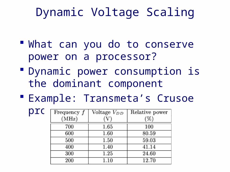
Dynamic Voltage Scaling
What can you do to conserve power on a processor?
Dynamic power consumption is the dominant component
Example: Transmeta’s Crusoe processor

DVS on Low Power Processor
Maximum gain when voltage is lowered BUT lower voltage increases circuit delay
M
1k
2ddkdynamic VfCP
2TDD
DD
)V(VV
τ
CMOS transistor threshold voltageTransistor gain factor
Dynamic Power Component
Number of gates
Load capacitance of gate k
Propagation delay

Voltage Scaling on LART
Dynamically lower the processor voltage and frequency to reduce power consumption
LART wearable board• StorngARM 1100 Processor 190MHz• Various I/O capabilities• 32 MB volatile memory• 4 MB non-volatile memory• Programmable voltage regulator

Processor Envelope
At 1.5V Max clock frequency 251MHzMin frequency the processor functions correctly is 59MHz

LART Power Measurement
• Note the measurement setup at Different levels on the board • Always provide hooks for measurement, testing and debugging during your design. Both for software and hardware!!!
Total Power Consumption on the LARTPlatform
Based on dhrystone benchmark

System Support Requirements
To manage DVS effectively, the computation requirements must be known in advance
Predictive scheme• Try to learn that behavior based on the computation profile
Better scheme: Applications should be power aware Processor frequency and scaling should be changed
without much delay• This is specific to each processor• 150us for the LART processor

Example: Power Aware Video Playback
Annotate a H.263 video decoder with information on the clock speed required to decode a known video sequence
Using a 12.6s video, 15fps
Power consumption measurements for LART• No-DVS: 198mW for CPU, 207mW for memory subsystem• DVS: 100mW for CPU and 204mW for the memory
subsystem• 2X improvement, but 25% improvement when memory
accesses are considered

LART Memory Performance
Memory access is optimal when high resolution memory access timing is available
For LART the optimal memory pattern:• 148MHz• 92 MB/s memory bandwidth• Power consumption 514.2mW• Energy cost 5.6mJ/MB

Power Budget Calculation Examples
Blackboard discussion• Duty cycling• Frequency scaling• Scheduling tasks tradeoffs

Some Platform Links
Check out the IPSN 2005 program http://www.ee.ucla.edu/~mbs/ipsn05/program.html
The poster and demo sessions contain links to several projects using a very wide variety of platforms