Embed Size (px)
Citation preview
SERIES
5-1
0C
OM
PR
ES
SO
RS
ER
IES
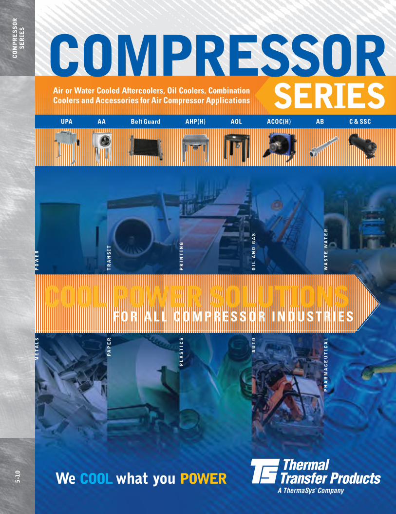
COOl POWER SOlUTIONSF o r a l l C o m p r e s s o r i n d u s T r i e s
upa aa belt Guard aHp(H) aol aCoC(H) ab C & ssC
air or water Cooled aftercoolers, oil Coolers, Combination Coolers and accessories for air Compressor applications
COMPRESSOR

roTary sCrew 200˚F (93˚C) 2-sTaGe pisTon 250˚F (121˚C) 1-sTaGe pisTon 300˚F (149˚C)
Compressor Capacity* Compressor Capacity* Compressor Capacity* model Hp (Kw) sCFm (Cmm) Hp (Kw) sCFm (Cmm) Hp (Kw) sCFm (Cmm)
UPA-20 5 (3.8) 35 (.99) — — — —
UPA-35 7.5 (5.6) 43 (1.22) 5 (3.8) 35 (.99) 5 (3.8) 31 (.88)
UPA-50 10 (7.5) 72 (2.04) 10 (7.5) 50 (1.42) 7.5 (5.6) 45 (1.27)
UPA-100 15-25 (11.2-18.6) 125 (3.54) 15-20 (11.2-14.9) 100 (2.83) 15-20 (11.2-14.9) 100 (2.83)
*For air flows above rated SCFM (CMM), use next larger size.
assumptions: n 80-125 PSIG (6-9 BAR) operating pressures 60 PSIG (4 BAR) minimum allowable. n Maximum pressure drop less than 3 PSIG (.2 BAR) at rated capacities. n A flexible metal hose should be properly installed between the compressor and aftercooler to validate warranty.
Air UPA
Materials Rating
The smallest size cooler in a wide family of choices. Copper tube construction offering a high efficiency, high performing compressed air cooler in compact package. Baked enamel finish for all-weather service. Four models with flow capacities from 5-125 SCFM (.14-3.5 SCMM) and used on compressors from 5-25 HP (3.7-18.6 KW). Detachable legs allow the cooler to be oriented vertical or horizontal.
Features
Model Selection
AIR COOlEd AFTERCOOlERS
n COPPER TUBE CONSTRUCTIONn Full Line of Sizes and Featuresn Energy Efficientn High Performancen Low flows to 100 CFM (2.83 CMM)n Detachable Legs (shipped unattached)
n Cabinet – Steel with Baked Enamel Finish n Core – Aluminum Fins on Copper Tubesn Fan – Heavy Gauge Aluminum with Steel Hubn Motor – Open Vented n Fan Guard – Zinc Chromate Plated Steel
n Maximum Operating Pressure 250 PSI (17 BAR)n Maximum Operating Temperature 350°F (177°C)
n Horizontal or Vertical Air Flown Lightweightn Ratings Based on Comprehensive Testingn Attractive, Durable Baked Enamel Finishn Floor or Suspended Mounting
Units shown with optional separator.

approx. Full shipping Fan motor load nema Thermal weightmodel CFm (Cmm) Hp (Kw) Voltage phase amps Hz rpm Frame overload lbs (Kg)
UPA-20 615 (17.40) 1/12 (.06) 115/230 1 60/50 1550/1300 Custom Yes 25 (11)
UPA-35 615 (17.40) 1/12 (.06) 115/230 1 2.4/1.2 60/50 1550/1300 Custom Yes 27 (12)
UPA-50 945 (26.76) 1/12 (.06) 115/230 1 2.7/1.4 60/50 1550/1300 Custom Yes 61 (28)
UPA-100 945 (26.76) 1/12 (.06) 115/230 1 60/50 1550/1300 Custom Yes 67 (30)
porT reCommended HoriZonTal air Flow VerTiCal air Flow ConneCTion opTional HeiGHT widTH depTH HeiGHT widTH depTH siZe separaTormodel inches mm inches mm inches mm inches mm inches mm inches mm npT model number
UPA-20 21.89 556 20.38 518 9.58 243 15.88 403 20.38 518 13.29 338 .50 S-50M or AD
UPA-35 21.89 556 20.38 518 9.58 243 15.88 403 20.38 518 13.29 338 .50 S-50M or AD
UPA-50 42.18 1071 26.11 663 20.93 532 40.12 1019 26.11 663 23.01 584 1.00 S-100M or AD
UPA-100 42.18 1071 26.11 663 20.93 532 40.12 1019 26.11 663 23.01 584 1.50 S-100M or AD
dimensions (approximate envelope)
UP
A
Motor & Fan data
Vertical air Flow
Horizontal air Flow
UPA-20 & UPA-35
Vertical air Flow
UPA-50 & UPA-100Horizontal air Flow
Height
Width
AIR FLOW
Depth
Inlet
Outlet
Height
Width
AIR FLOW
Depth
Inlet Outlet
Height
Width
AIR FLOW
Depth
Inlet
Outlet
Height
Width
AIR FLOW
Depth
Outlet
Air AA
Materials Rating
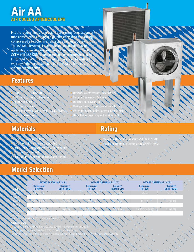
Fits the requirements for medium performing ranges. Copper tube construction offering a high efficiency, high performing compressed air cooler in an attractive galvanized steel cabinet. The AA Series works in numerous common compressor applications. Six models with flow capacities from 16-480 SCFM (.45-13.6 SCMM) and used on compressors from 5-60 HP (3.7-44.7 KW). The free standing cooler can be ordered with a weather proof Junction box and wired for a single point electrical connection.
Features
Model Selection
AIR COOlEd AFTERCOOlERS
n COPPER TUBE CONSTRUCTION n Full Line of Sizes and Featuresn Energy Efficientn High Performancen Medium Flows 80-300 CFM (2.27-8.50 CMM)n Horizontal Air Flow
n Cabinet – Galvanized Steel n Core – Aluminum Fins on Copper Tubesn Fan – Heavy Gauge Aluminum with Steel Hubn Motor – Open Vented n Fan Guard – Steel with Baked Enamel Finish
n Maximum Operating Pressure 250 PSI (17 BAR)n Maximum Operating Temperature 350°F (177°C)
n Optional Weatherproof Junction Boxn Floor or Suspended Mountingn Optional TEFC Motor(s)n Ratings Based on Comprehensive Testingn Wired for Single Point External Connectionn Detachable Legs (shipped unattached)
roTary sCrew 200˚F (93˚C) 2-sTaGe pisTon 250˚F (121˚C) 1-sTaGe pisTon 300˚F (149˚C)
Compressor Capacity* Compressor Capacity* Compressor Capacity*model Hp (Kw) sCFm (Cmm) Hp (Kw) sCFm (Cmm) Hp (Kw) sCFm (Cmm)
AA-50 5-10 (3.7-7.5) 59 (1.67) 5-10 (3.7-7.5) 50 (1.42) 5 (3.7) 42 (1.19)
AA-80 15 (11.2) 94 (2.66) 15 (11.2) 80 (2.27) 10 (7.5) 71 (2.01)
AA-120 20-25 (14.9-18.6) 142 (4.02) 20 (14.9) 120 (3.40) 15 (11.2) 102 (2.89)
AA-150 30 (22.4) 172 (4.87) 25-30 (18.6-22.4) 150 (4.25) 20-25 (14.9-18.6) 130 (3.68)
AA-240 40-50 (29.8-37.2) 285 (8.07) 35-45 (26.1-33.6) 240 (6.80) 30-40 (22.4-29.8) 204 (5.78)
AA-300 60 (44.7) 345 (9.77) 50-60 (37.2-44.7) 300 (8.50) 45-50 (33.6-37.2) 257 (7.28)
*For air flows above rated SCFM (CMM), use next larger size.
assumptions: n 80-125 PSIG (6-9 BAR) operating pressures 60 PSIG (4 BAR) minimum allowable. n Maximum pressure drop less than 3 PSIG (.2 BAR) at rated capacities. n A flexible metal hose should be properly installed between the compressor and aftercooler to validate warranty.
sTandard opTional opTional approx. moTor (odp) moTor (TeFC) moTor (TeFC)* shipping air moTor
Fan motor Full load Full load Full load weight psi CFm model CFm (Cmm) Hp (Kw) Voltage amps/motor Voltage amps/motor Voltage amps/motor lbs. (Kg) (bar) (Cmm)
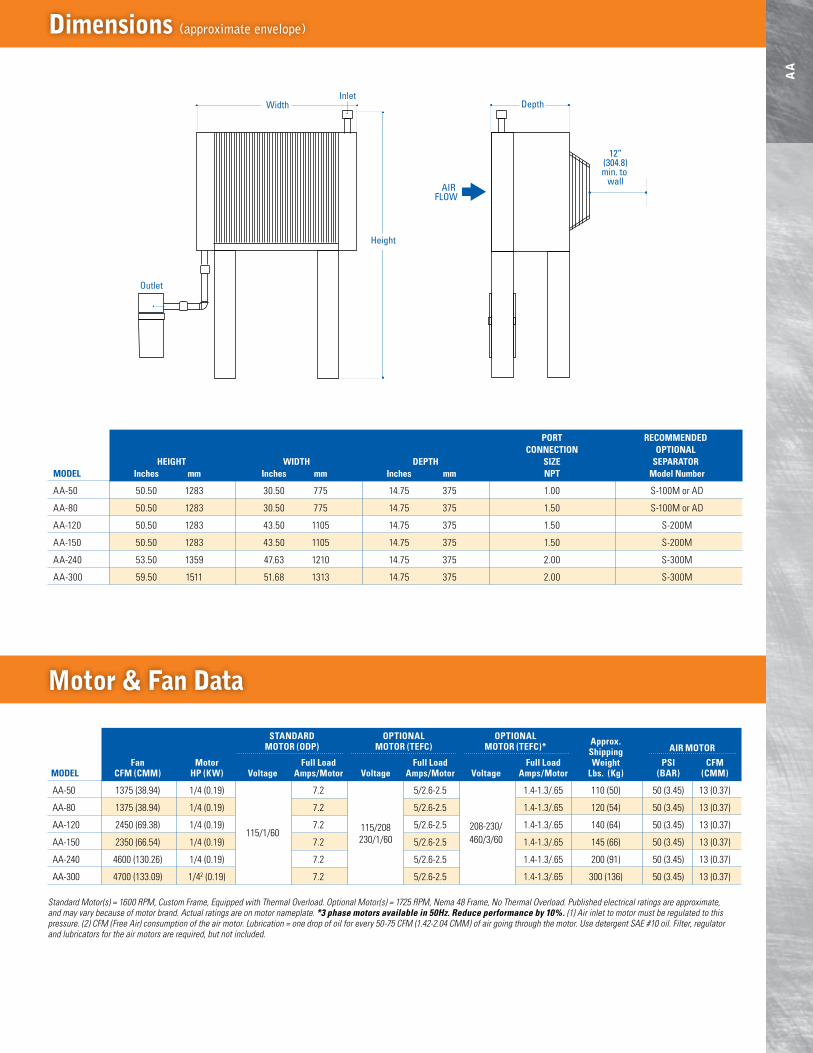
AA-50 1375 (38.94) 1/4 (0.19) 7.2 5/2.6-2.5 1.4-1.3/.65 110 (50) 50 (3.45) 13 (0.37)
AA-80 1375 (38.94) 1/4 (0.19) 7.2 5/2.6-2.5 1.4-1.3/.65 120 (54) 50 (3.45) 13 (0.37)
AA-120 2450 (69.38) 1/4 (0.19) 115/1/60
7.2 115/208 5/2.6-2.5 208-230/ 1.4-1.3/.65 140 (64) 50 (3.45) 13 (0.37)
AA-150 2350 (66.54) 1/4 (0.19) 7.2 230/1/60 5/2.6-2.5 460/3/60 1.4-1.3/.65 145 (66) 50 (3.45) 13 (0.37)
AA-240 4600 (130.26) 1/4 (0.19) 7.2 5/2.6-2.5 1.4-1.3/.65 200 (91) 50 (3.45) 13 (0.37)
AA-300 4700 (133.09) 1/42 (0.19) 7.2 5/2.6-2.5 1.4-1.3/.65 300 (136) 50 (3.45) 13 (0.37)
dimensions (approximate envelope)
AA
Motor & Fan data
Standard Motor(s) = 1600 RPM, Custom Frame, Equipped with Thermal Overload. Optional Motor(s) = 1725 RPM, Nema 48 Frame, No Thermal Overload. Published electrical ratings are approximate, and may vary because of motor brand. Actual ratings are on motor nameplate. *3 phase motors available in 50Hz. Reduce performance by 10%. (1) Air inlet to motor must be regulated to this pressure. (2) CFM (Free Air) consumption of the air motor. Lubrication = one drop of oil for every 50-75 CFM (1.42-2.04 CMM) of air going through the motor. Use detergent SAE #10 oil. Filter, regulator and lubricators for the air motors are required, but not included.
Height
Width
AIR FLOW
12”(304.8)min. to
wall
Depth
Height
Width
AIR FLOW
12”(304.8)min. to
wall
Depth
Outlet
Inlet
porT reCommended ConneCTion opTional HeiGHT widTH depTH siZe separaTormodel inches mm inches mm inches mm npT model number
AA-50 50.50 1283 30.50 775 14.75 375 1.00 S-100M or AD
AA-80 50.50 1283 30.50 775 14.75 375 1.50 S-100M or AD
AA-120 50.50 1283 43.50 1105 14.75 375 1.50 S-200M
AA-150 50.50 1283 43.50 1105 14.75 375 1.50 S-200M
AA-240 53.50 1359 47.63 1210 14.75 375 2.00 S-300M
AA-300 59.50 1511 51.68 1313 14.75 375 2.00 S-300M

maximum maximum model sCFm* Cmm model raTinG approaCH TemperaTure
BGA-35-2/1 35 .99 5˚F for 18 SCFM 15˚F for 35 SCFM 3˚C for .51 CMM 8˚C for .99 CMM
BGA-60-2/1 60 1.70 10˚F for 35 SCFM 25˚F for 60 SCFM 6˚C for .99 CMM 14˚C for 1.70 CMM
BGA-100-2/1 100 2.83 13˚F for 70 SCFM 25˚F for 100 SCFM 7˚C for 1.98 CMM 14˚C for 2.83 CMM;
maximum maximummodel sCFm* Cmm
M-15-76946 20 .57
M-20-76785 35 .99
M-25-76878 75 2.12
M-30-76941 100 2.83
Air Belt Guard
Materials Rating
No fan motor required via mounting to compressor belt guard. These coolers, built from either round cooper tube & fin or bar & plate brazed aluminum construction, allow the use of free air flow from the belt guard on reciprocating compressors. Compact and light weight, the Belt Guard Series is offered in seven models with capacities from 20-100 SCFM (.57-2.8 KW).
Features M Models
Model Selection
AIR COOlEd AFTERCOOlERS
n COPPER TUBE CONSTRUCTION n Utilizes Air Flow from Belt Guard on Recip Compressorn Easy to Installn Rugged Constructionn Solid Performancen Bolt directly on the existing belt guard (some additional support
may be required)n All steel manifolds with sturdy copper tubes and aluminum finsn Unique turbulator inside each cooling tube assures maximum
performance in a compact size
n Tubes – Copper n Fins – Aluminumn Turbulators – Steeln Manifolds – Steel
n Maximum Operating Pressure 300 PSI (21 BAR)
n Maximum Operating Temperature 350°F (177°C)
* Ratings are based on a 250°F (121°C) inlet temperature, 100 PSIG (7 BAR), and 500 FPM (152.4 MPM) air face velocity across the ambient side of the aftercooler. Maximum pressure drop is 3 PSI (.21 BAR) or less—all models. 25°F (14°C) approach temperature, unless stated otherwise.
Materials Ratingn Core – Brazed Aluminum
Bar & Platen Maximum Operating
Pressure 250 PSI (17 BAR)n Maximum Operating
Temperature 350°F (177°C)
n BRAZED ALUMINUM CONSTRUCTION n Brazed Bar and Plate Aluminum Core n Energy Efficientn High Performance n High Technology Compact Design n Rugged Heavy Duty Construction n Excellent for Heat Recovery
Features BGA Models
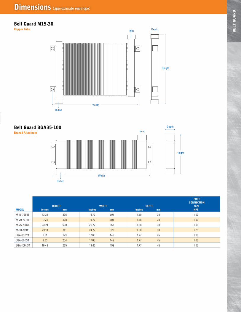
porT ConneCTion HeiGHT widTH depTH siZemodel inches mm inches mm inches mm npT
M-15-76946 13.24 336 19.72 501 1.50 38 1.00
M-20-76785 17.24 438 19.72 501 1.50 38 1.00
M-25-76878 23.24 590 25.72 653 1.50 38 1.00
M-30-76941 29.18 741 24.72 628 1.50 38 1.25
BGA-35-2/1 6.81 173 17.68 449 1.77 45 1.00
BGA-60-2/1 8.03 204 17.68 449 1.77 45 1.00
BGA-100-2/1 10.43 265 19.65 499 1.77 45 1.00
dimensions (approximate envelope)
BE
lT G
UA
Rd
Height
Width
Depth
Height
Width
Depth
Outlet
Inlet
Outlet
Inlet
Height
Width
Depth
Height
Width
Depth
Outlet
Inlet
Outlet
Inlet
Belt Guard M15-30Copper Tube
Belt Guard BGA35-100brazed aluminum

roTary sCrew 200˚F (93˚C) 2-sTaGe pisTon 250˚F (121˚C) 1-sTaGe pisTon 300˚F (149˚C)
Compressor Capacity* Compressor Capacity* Compressor Capacity*model Hp (Kw) sCFm (Cmm) Hp (Kw) sCFm (Cmm) Hp (Kw) sCFm (Cmm)
AHP(H)-400 75 (56.2) 430 (12.18) 75 (56.2) 400 (11.33) 60 (44.7) 340 (9.63)
AHP(H)-725 100-150 (74.5-111.8) 760 (21.52) 100-125 (74.5-93.2) 725 (20.53) 75-100 (56.2-74.5) 605 (17.13)
AHP(H)-950 175-200 (130.0-149.1) 1020 (28.88) 150-175 (111.8-130.0) 950 (26.90) 125-150 (93.2-111.8) 785 (22.23)
AHP(H)-1200 250 (186.4) 1290 (36.53) 200 (149.1) 1200 (33.98) 175-200 (130.0-149.1) 980 (27.75)
AHP(H)-1600 300 (223.7) 1720 (48.70) 250-300 (186.4-223.7) 1600 (45.31) 250 (186.4) 1290 (36.53)
AHP(H)-2000 400 (298.2) 2140 (60.60) 350-400 (261.0-298.2) 2000 (56.63) 300 (223.7) 1595 (45.17)
AHP(H)-2500 450-500 (335.6-372.9) 2680 (75.89) 450-500 (335.6-372.9) 2500 (70.79) 350 (261.0) 1980 (56.07)
AHP-3000 600-650 (447.4-484.7) 3200 (90.61) 550-600 (410.1-447.4) 3000 (84.95) 400-450 (298.2-335.6) 2360 (66.83)
AHP-3500 700-750 (522.0-559.3) 3760 (106.47) 700 (522.0) 3500 (99.11) 500-550 (372.9-410.1) 2760 (78.15)
*For air flows above rated SCFM (CMM), use next larger size.
assumptions: n 80-125 PSIG (6-9 BAR) operating pressures 60 PSIG (4 BAR) minimum allowable. n Maximum pressure drop less than 3 PSIG (.2 BAR) at rated capacities. n 15˚F (8˚C) approach temperaturen A flexible metal hose should be properly installed between the compressor and aftercooler to validate warranty.
Air AHP/AHPH
n BRAZED ALUMINUM CONSTRUCTION n Full Line of Sizes and Features n Brazed Bar and Plate Aluminum Core n Energy Efficient n Vertical (AHP) or Horizontal (AHPH) Air Flown High Performance
n Cabinet – Steel with Baked Enamel Finishn Core – Brazed Aluminum Bar and Plate n Fan – Aluminum Hub, Polypropylene Bladesn Shroud – Painted Steeln Motor – TEFC/optional Airn Fan Guard – Steel with Baked Enamel Finish
n Maximum Operating Pressure 250 PSI (17 BAR)n Maximum Operating Temperature 350°F (177°C)
Materials Rating
Our highest performing aftercooler, the AHP and AHPH are built from high-performance plate & bar aluminum construction. Energy efficient, durable and flexible mounting in horizontal or vertical configurations. The finish is a rugged black powder coating. Nine models with flow capacities from 125-4800 SCFM (3.5-135.9 SCMM) and used on compressors from 60-700 HP (44.7-522 KW). Fan options include electrical TEFC and air motor drive. The legs ship detached to allow the cooler to be installed in numerous configurations.
n High Technology Compact Design n High Flows 400-3500 CFM (11.33-99.11 CMM) n Optional Air Motor n Rugged Heavy Duty Construction n Excellent for Heat Recovery n Detachable Legs on AHP (shipped unattached)
Fixed Mounting Feet on AHPH
Features
Model Selection
AIR COOlEd AFTERCOOlERS

approx. Full shipping sound air moTor
Fan motor load nema Thermal weight db(a) psi1 CFm2
model CFm (Cmm) Hp (Kw) Voltage phase amps Hz rpm Frame overload lbs. (Kg) at 3 ft (bar) (Cmm)
AHP(H)-400 2200 (62.3) 1.0 (.75) 115/208-230 1 6.0 60 3450 56C No 120 (54) 97 60 (4.14) 50 (1.42)
1825/2200 (51.68/62.3) 1.0 (.75) 208-230/460 3 3.6/3.2 50/60 2850/3450 56C No 120 (54) 97 60 (4.14) 50 (1.42)
AHP(H)-725 3600 (101.94) 1.5 (1.12) 115/208-230 1 8.5 60 3450 56C No 170 (77) 100 85 (5.86) 65 (1.84)
3025/3600 (85.66/101.94) 1.5 (1.12) 208-230/460 3 4.8/4.2 50/60 2850/3450 56C No 170 (77) 100 85 (5.86) 65 (1.84)
AHP(H)-950 4700 (133.09) 1.5 (1.12) 115/208-230 1 8.6 60* 1740 145TC No 330 (150) 92 60 (4.14) 55 (1.56)
4700 (133.09) 1.5 (1.12) 208-230/460 3 4.6 60* 1740 145TC No 330 (150) 92 60 (4.14) 55 (1.56)
AHP(H)-1200 7000 (198.22) 5.0 (3.73) 230 1 23.0 60* 1740 184TC No 450 (204) 94 70 (4.83) 100 (2.83)
7000 (198.22) 3.0 (2.24) 208-230/460 3 8.8 60* 1740 182TC No 450 (204) 94 70 (4.83) 100 (2.83)
AHP(H)-1600 9700 (274.67) 5.0 (3.73) 208-230/460 3 13.4 60* 1740 184TC No 515 (234) 96 100 (6.89) 180 (5.10)
AHP(H)-2000 11000 (311.49) 7.5 (5.59) 230/460 3 19.6 60* 1740 213TC No 600 (272) 98 90 (6.21) 230 (6.51)
AHP-2500 14000 (396.44) 7.5 (5.59) 230/460 3 24.8 60* 1740 213TC No 625 (284) 98 90 (6.21) 230 (6.51)
AHP-3000 17500 (495.54) 10.0 (7.46) 230/460 3 24.8 60* 1740 215TC No 645 (293) 102 100 (6.89) 275 (7.79)
AHP-3500 17500 (495.54) 10.0 (7.46) 230/460 3 24.8 60* 1740 215TC No 750 (340) 102 100 (6.89) 275 (7.79)
porT reCommended aHp aHpH ConneCTion opTional HeiGHT widTH depTH HeiGHT widTH depTH siZe separaTormodel inches mm inches mm inches mm inches mm inches mm inches mm npT model number
AHP(H) -400 34.20 869 26.22 666 17.96 456 19.95 507 22.45 570 17.48 444 2.00 S-600M
AHP(H) -725 34.20 869 34.10 866 22.37 568 24.37 619 30.17 766 20.86 530 2.00 S-600M
AHP(H) -950 36.01 915 40.78 1036 26.78 680 28.82 723 35.89 912 22.69 576 3.00 S-1700M
AHP(H) -1200 36.01 915 44.73 1136 26.78 680 28.82 732 40.31 1024 24.07 611 3.00 S-1700M
AHP(H) -1600 36.01 915 44.73 1136 34.89 886 36.89 937 40.31 1024 25.45 646 3.00 S-2600M
AHP(H) -2000 36.01 915 54.58 1386 37.88 962 39.53 1004 48.29 1227 26.77 680 4.00 S-2600M
AHP-2500 36.01 915 52.61 1336 43.70 1110 — — — — — — 4.00 S-2600M
AHP-3000 36.01 915 54.58 1386 52.52 1334 — — — — — — 4.00 S-2600M
AHP-3500 36.01 915 54.58 1386 56.30 1430 — — — — — — 4.00 S-2600M
All motors shown are TEFC. Other motor options available upon request. Published electrical ratings are approximate, and may vary because of motor brand. Actual ratings are on motor nameplate. Fan motors must not be cycled. Outdoor applications must be protected from direct weather. If ductwork or additional static resistance is added to the cooler airstream, an auxiliary air mover may be required.*3 phase motors available in 50Hz. Reduce performance by 10%.1 Air inlet to the air motor must be regulated to this pressure.2 CFM (Free Air) consumption of the air motor. Lubrication = One drop of oil for every 50-75 CFM (1.42-2.12 CMM) of air going through the motor. Use detergent SAE #10 oil. Filter, regulator and lubricators
for the air motors are required, but not included.
dimensions (approximate envelope)
AH
P /
AH
PH
Height
Width
AIR FLOW
Connection Port2 places
Connection Port2 places
Depth
Motor & Fan data
Height
Width (over brackets) Depth
AIR FLOW
Connection Port2 places
Connection Port2 places
Inlet
Outlet
AHP AHPH
Compressor Flow range*model Hp (Kw) Gpm (lpm)
AOL-1600 165-215 (123.04-160.33) 50-65 (189-246)
AOL-2000 215-285 (160-33-212.52) 70-90 (265-341)
AOL-2500 295-335 (219.98-249.81) 90-100 (341-379)
AOL-3000 345-400 (257.27-298.28) 100-120 (379-454)
AOL-3500 400-450 (298.28-335.56) 120-140 (454-530)
Compressor Flow range*model Hp (Kw) Gpm (lpm)
AOL-400 35-45 (26.10-33.56) 15-20 (57-76)
AOL-725 45-85 (33.56-63.38) 25-40 (95-151)
AOL-950 85-135 (63.38-100.67) 40-50 (151-189)
AOL-1200 135-165 (100.67-123.04) 50-60 (189-227)
* Oil pressure drop less than 15 PSI (1.03 BAR) for specified flow ranges.
assumptions: n Heat Rejection = .85 x Compressor HP n 100°F (56°C ) ETD (Oil In - Ambient Air) n 150 SSU Average Viscosity Oil
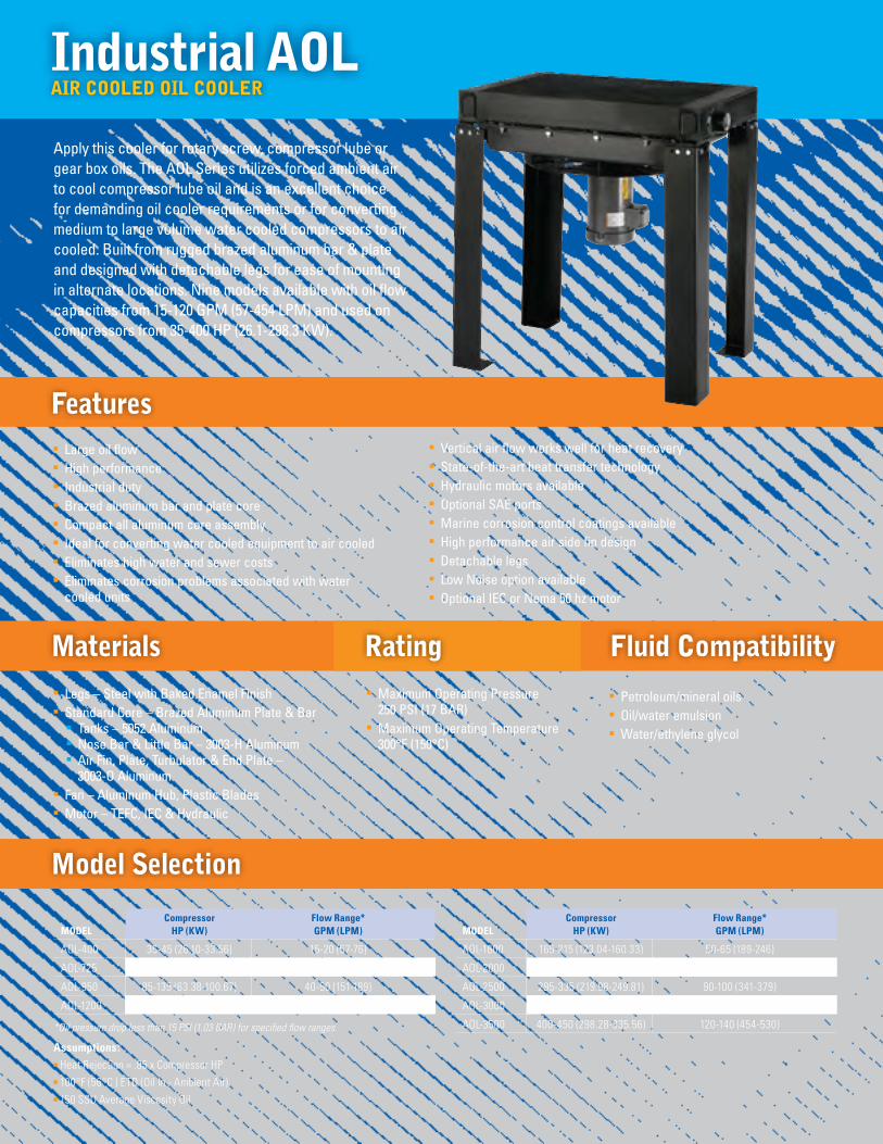
Industrial AOL
Model Selection
AIR COOlEd OIl COOlER
n Large oil flown High performancen Industrial dutyn Brazed aluminum bar and plate coren Compact all aluminum core assemblyn Ideal for converting water cooled equipment to air cooledn Eliminates high water and sewer costs n Eliminates corrosion problems associated with water
cooled units
Featuresn Vertical air flow works well for heat recoveryn State-of-the-art heat transfer technology n Hydraulic motors availablen Optional SAE portsn Marine corrosion control coatings availablen High performance air side fin designn Detachable legs n Low Noise option availablen Optional IEC or Nema 50 hz motor
Apply this cooler for rotary screw, compressor lube or gear box oils. The AOL Series utilizes forced ambient air to cool compressor lube oil and is an excellent choice for demanding oil cooler requirements or for converting medium to large volume water cooled compressors to air cooled. Built from rugged brazed aluminum bar & plate and designed with detachable legs for ease of mounting in alternate locations. Nine models available with oil flow capacities from 15-120 GPM (57-454 LPM) and used on compressors from 35-400 HP (26.1-298.3 KW).
n Petroleum/mineral oils n Oil/water emulsion n Water/ethylene glycol
n Maximum Operating Pressure 250 PSI (17 BAR)
n Maximum Operating Temperature 300°F (150°C)
n Legs – Steel with Baked Enamel Finishn Standard Core – Brazed Aluminum Plate & Bar
n Tanks – 5052 Aluminumn Nose Bar & Little Bar – 3003-H Aluminumn Air Fin, Plate, Turbulator & End Plate –
3003-O Aluminumn Fan – Aluminum Hub, Plastic Bladesn Motor – TEFC, IEC & Hydraulic
Materials Rating Fluid Compatibility

porT approximate ConneCTion shipping HeiGHT depTH widTH siZe weightmodel inches mm inches mm inches mm npT lbs Kg
AOL-400 34.20 869 17.96 456 26.23 666 2.00 148 67
AOL-725 34.20 869 22.37 568 34.11 866 2.00 170 77
AOL-950 36.01 915 26.78 681 40.79 1036 2.00 300 136
AOL-1200 36.01 915 26.78 681 44.74 1136 2.00 430 195
AOL-1600 36.01 915 34.89 886 44.74 1136 2.50 515 234
AOL-2000 36.01 915 37.88 962 54.59 1387 2.50 582 264
AOL-2500 36.01 915 43.70 1110 52.62 1337 3.00 655 297
AOL-3000 36.01 915 52.52 1334 54.59 1387 3.00 825 374
AOL-3500 36.01 915 56.30 1430 54.59 1387 3.00 860 390
Fan motor Full load nema Thermal soundmodel CFm (Cmm) Hp (Kw) Voltage phase amps 230V Hz rpm Frame overload db(a) at 3 ft.
AOL-400 2200 (62.30) 1.0 (.75) 115/208-230 1 6.0 60(2) 3450 56C No 97
1825/2200 (51.68/62.30) 1.0 (.75) 208-230/460(3) 3 3.6/3.2 50/60 2850/3450 56C No 97
AOL-725 3600 (101.94) 1.5 (1.12) 115/208-230 1 8.5 60(2) 3450 56C No 100
3000/3600 (84.95/102.94) 1.5 (1.12) 208-230/460(4) 3 4.8/4.2 50/60 2850/3450 56C No 100
AOL-950 4700 (133.09) 1.5 (1.12) 115/208-230 1 8.6 60(2) 1740 145TC No 92
4700 (133.09) 1.5 (1.12) 208-230/460 3 4.6 60(2) 1740 145TC No 92
AOL-1200 7000 (198.22) 5.0 (3.73) 230 1 23.00 60(2) 1740 184TC No 94
7000 (198.22) 3.0 (2.24) 208-230/460 3 8.8 60(2) 1740 182TC No 96
AOL-1600 9700 (223.70) 5.0 (3.73) 208-230/460 3 13.4 60(2) 1740 184TC No 98
AOL-2000 11000 (311.49) 7.5 (5.59) 230/460 3 19.6 60(2) 1740 213TC No 98
AOL-2500 14000 (396.44) 7.5 (5.59) 230/460 3 19.6 60(2) 1740 213TC No 98
AOL-3000 17500 (495.54) 10.0 (7.46) 230/460 3 24.8 60(2) 1740 215TC No 102
AOL-3500 17500 (495.54) 10.0 (7.46) 230/460 3 24.8 60(2) 1740 215TC No 102
dimensions (approximate envelope)
AO
l
Motor & Fan data(1) (60 Hz Nema Frame)
(1) Published electrical ratings are approximate, and may vary because of motor brand. Actual ratings are on motor nameplate.(2) May also be operated at 50 hz. Consult factory for details. (3) 50 Hz voltage: 190-200-208-220/380-400-415-440 (4) 50 Hz voltage: 190-208/380-415All motors shown are TEFC—Other motor options available upon request.
Height
Width AIR FLOW
Depth
Height
Width AIR FLOW
Depth
Inlet / Outlet(Interchangeable)
Inlet / Outlet(Interchangeable)

Compressor maximummodel Hp (Kw) sCFm (Cmm)
ACOC(H)-400 15-35 (11.90-26.10) 175 (4.96)
ACOC(H)-725 40-55 (29.83-41.01) 275 (7.79)
ACOC(H)-950 60-85 (44.74-63.38) 425 (12.03)
ACOC(H)-1200 90-120 (67.11-89.48) 600 (16.99)
ACOC(H)-1600 125-155 (93.21-115.58) 775 (21.95)
ACOC(H)-2000 160-225 (119.31-167.78) 1125 (31.86)
ACOC-2500 230-275 (171.51-205.07) 1375 (38.94)
ACOC-3000 280-325 (208.08-242.35) 1625 (46.01)
ACOC-3500 330-360 (246.08-268.45) 1800 (50.97)
Air ACOC / ACOCH
Model Selection
AIR COOlEd COMBINATION (OIl COOlER / AFTERCOOlER)
n BRAZED ALUMINUM CONSTRUCTION n Combination Welded Cores – Air & Oil Core n Brazed Aluminum Core/Bar and Plate n Excellent for Field Conversions n Vertical (ACOC) or Horizontal (ACOCH) Air Flow n Compact Design n Light Weightn State-of-the-art heat transfer technology
n Legs – Steel with Baked Enamel Finishn Shroud – Steel n Core – Brazed Aluminum Bar and Platen Fan – Aluminum Hub, Plastic Bladesn Motor – TEFC
n Maximum Operating Pressure 250 PSI (17 BAR)n Maximum Operating Temperature 350°F (177°C)
Materials Rating
The best of both worlds in one compact, side by side, combination package. Cools rotary screw compressor oil and compressed air in a single combined core. Ideal for conversions, stringent space requirements and remote location mounting. Built from rugged brazed aluminum bar & plate and designed with detachable legs for ease of mounting, and now available in vertical orientation. Fifteen models with flow capacities from 175-1800 SCFM (4.96-50.97 SCMM) and used on compressors from 15-360 HP (11.2-268.5 KW).
n Compact, high performance all aluminum core assembly
n Designed specifically for rotary screw compressors n Ideal for converting water cooled units to air cooled n Eliminates high water and sewer costs n Eliminates corrosion problems associated with water cooled units n Vertical air flow works well for heat recovery n Detachable Legs on ACOC (shipped unattached)/Fixed Mounting Feet on ACOCH
Features
bottom view of cooler to illustrate piping
Receiver
Dryer
Separator/Trap/Drain
Heat Exchanger
To Plant
Relief Valve
Coalescing Filter
Air to Air Reheater
Air/Oil Separator
Flexible Connector
Compressor
Thermal By-Pass Valve
assumptions: n 100 PSI (7 BAR) air n 15°F (8°C ) ETD approach temperaturen Oil flow is .45 GPM/HP (1.4 L/KW) n Oil pressure drop 15 PSI (1.03 BAR) or lessn Oil heat transfer based on 100°F (56°C ) ETD (ETD = Entering Temperature Difference) ( ETD = Oil in Temperature - Ambient Air Temperature)n Air aftercooler pressure drop 3 PSI (.21 BAR) or less. n ETD Temperature Correction Factor: HPchart = HPcompressor x 100°F (56°C )
desired ETD
oil Cooler
air aFTerCooler
oil Cooler
air aFTerCooler
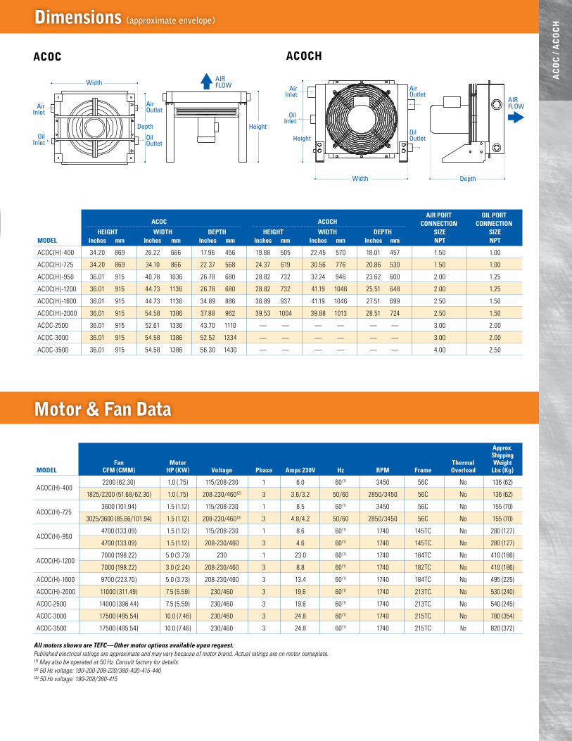
approx. shipping Fan motor Thermal weightmodel CFm (Cmm) Hp (Kw) Voltage phase amps 230V Hz rpm Frame overload lbs (Kg)
ACOC(H)-400 2200 (62.30) 1.0 (.75) 115/208-230 1 6.0 60(1) 3450 56C No 136 (62)
1825/2200 (51.68/62.30) 1.0 (.75) 208-230/460(2) 3 3.6/3.2 50/60 2850/3450 56C No 136 (62)
ACOC(H)-725 3600 (101.94) 1.5 (1.12) 115/208-230 1 8.5 60(1) 3450 56C No 155 (70)
3025/3600 (85.66/101.94) 1.5 (1.12) 208-230/460(3) 3 4.8/4.2 50/60 2850/3450 56C No 155 (70)
ACOC(H)-950 4700 (133.09) 1.5 (1.12) 115/208-230 1 8.6 60(1) 1740 145TC No 280 (127)
4700 (133.09) 1.5 (1.12) 208-230/460 3 4.6 60(1) 1740 145TC No 280 (127)
ACOC(H)-1200 7000 (198.22) 5.0 (3.73) 230 1 23.0 60(1) 1740 184TC No 410 (186)
7000 (198.22) 3.0 (2.24) 208-230/460 3 8.8 60(1) 1740 182TC No 410 (186)
ACOC(H)-1600 9700 (223.70) 5.0 (3.73) 208-230/460 3 13.4 60(1) 1740 184TC No 495 (225)
ACOC(H)-2000 11000 (311.49) 7.5 (5.59) 230/460 3 19.6 60(1) 1740 213TC No 530 (240)
ACOC-2500 14000 (396.44) 7.5 (5.59) 230/460 3 19.6 60(1) 1740 213TC No 540 (245)
ACOC-3000 17500 (495.54) 10.0 (7.46) 230/460 3 24.8 60(1) 1740 215TC No 780 (354)
ACOC-3500 17500 (495.54) 10.0 (7.46) 230/460 3 24.8 60(1) 1740 215TC No 820 (372)
air porT oil porT aCoC aCoCH ConneCTion ConneCTion HeiGHT widTH depTH HeiGHT widTH depTH siZe siZemodel inches mm inches mm inches mm inches mm inches mm inches mm npT npT
ACOC(H)-400 34.20 869 26.22 666 17.96 456 19.88 505 22.45 570 18.01 457 1.50 1.00
ACOC(H) -725 34.20 869 34.10 866 22.37 568 24.37 619 30.56 776 20.86 530 1.50 1.00
ACOC(H) -950 36.01 915 40.78 1036 26.78 680 28.82 732 37.24 946 23.62 600 2.00 1.25
ACOC(H) -1200 36.01 915 44.73 1136 26.78 680 28.82 732 41.19 1046 25.51 648 2.00 1.25
ACOC(H) -1600 36.01 915 44.73 1136 34.89 886 36.89 937 41.19 1046 27.51 699 2.50 1.50
ACOC(H) -2000 36.01 915 54.58 1386 37.88 962 39.53 1004 39.88 1013 28.51 724 2.50 1.50
ACOC-2500 36.01 915 52.61 1336 43.70 1110 — — — — — — 3.00 2.00
ACOC-3000 36.01 915 54.58 1386 52.52 1334 — — — — — — 3.00 2.00
ACOC-3500 36.01 915 54.58 1386 56.30 1430 — — — — — — 4.00 2.50
dimensions (approximate envelope)
AC
OC
/ A
CO
CH
Motor & Fan data
All motors shown are TEFC—Other motor options available upon request.Published electrical ratings are approximate and may vary because of motor brand. Actual ratings are on motor nameplate. (1) May also be operated at 50 Hz. Consult factory for details. (2) 50 Hz voltage: 190-200-208-220/380-400-415-440(3) 50 Hz voltage: 190-208/380-415
ACOC ACOCH
Height
Width AIR FLOW
Depth
AirInlet
OilInlet
AirOutlet
OilOutlet
Height
Width Depth
AIR FLOW
AirInlet
OilInlet
AirOutlet
OilOutlet
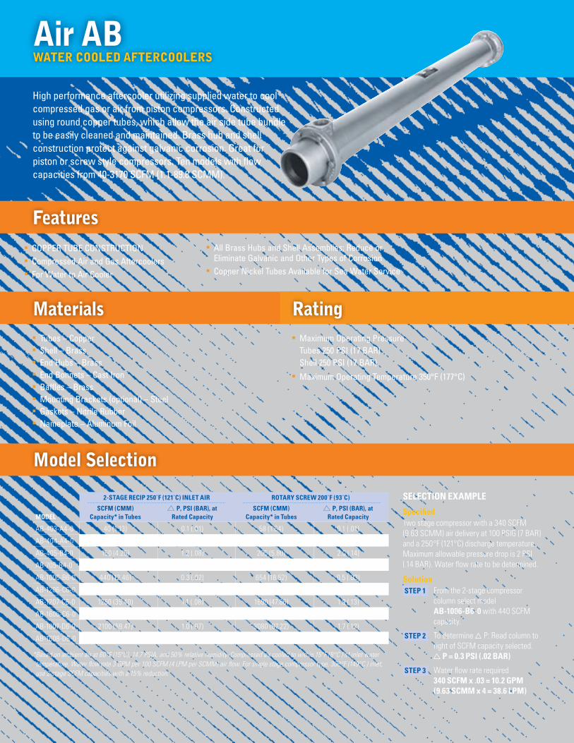
2-sTaGe reCip 250˚F (121˚C) inleT air roTary sCrew 200˚F (93˚C)
sCFm (Cmm) p, psi (bar), at sCFm (Cmm) p, psi (bar), atmodel Capacity* in Tubes rated Capacity Capacity* in Tubes rated Capacity
AB-403-A4-0 40 (1.13) 0.1 (.01) 58 (1.64) 0.1 (.01)
AB-404-A4-0 80 (2.27) 0.3 (.02) 110 (3.11) 0.6 (.04)
AB-405-B4-0 150 (4.25) 1.2 (.08) 205 (5.80) 2.0 (.14)
AB-705-B4-0 310 (8.78) 1.0 (.07) 439 (12.43) 1.6 (.11)
AB-1006-B6-0 440 (12.46) 0.3 (.02) 654 (18.52) 0.5 (.03)
AB-1206-C6-0 640 (18.12) 0.3 (.02) 955 (27.04) 0.6 (.04)
AB-1207-C6-0 1250 (35.40) 1.1 (.08) 1690 (47.86) 1.9 (.13)
AB-1606-C6-0 1600 (45.31) 0.5 (.03) 2280 (64.56) 0.9 (.06)
AB-1607-D6-0 2100 (59.47) 1.0 (.07) 3080 (87.22) 1.7 (.12)
AB-1608-D6-0 2800 (79.29) 1.6 (.11) 3170 (89.76) 2.0 (.14)
* Based on ambient air at 60°F (15°C), 14.7 PSIA, and 50% relative humidity. Compressed air cooled to within 15°F (8°C ) of inlet water temperature. Water flow rate 3 GPM per 100 SCFM (4 LPM per SCMM) air flow. For single stage compressor type, 300°F (149°C ) inlet, use 2-stage SCFM capacities with a 15% reduction.
Air AB
Model Selection
WATER COOlEd AFTERCOOlERS
n COPPER TUBE CONSTRUCTION n Compressed Air and Gas Aftercoolers n For Water to Air Cooler
n Tubes – Coppern Shell – Brass n End Hubs – Brass n End Bonnets – Cast Ironn Baffles – Brassn Mounting Brackets (optional) – Steel n Gaskets – Nitrile Rubbern Nameplate – Aluminum Foil
n Maximum Operating Pressure Tubes 250 PSI (17 BAR) Shell 250 PSI (17 BAR)
n Maximum Operating Temperature 350°F (177°C)
Materials Rating
High performance aftercooler utilizing supplied water to cool compressed gas or air from piston compressors. Constructed using round copper tubes, which allow the air side tube bundle to be easily cleaned and maintained. Brass hub and shell construction protect against galvanic corrosion. Great for piston or screw style compressors. Ten models with flow capacities from 40-3170 SCFM (1.1-89.8 SCMM).
Features n All Brass Hubs and Shell Assemblies: Reduce or
Eliminate Galvanic and Other Types of Corrosion n Copper Nickel Tubes Available for Sea Water Service
seleCTion example
specified Two stage compressor with a 340 SCFM (9.63 SCMM) air delivery at 100 PSIG (7 BAR) and a 250°F (121°C) discharge temperature. Maximum allowable pressure drop is 2 PSI (.14 BAR). Water flow rate to be determined.
solution sTep 1 From the 2-stage compressor
column select model ab-1006-b6-0 with 440 SCFM capacity.
sTep 2 To determine P: Read column to right of SCFM capacity selected.
p = 0.3 psi (.02 bar)
sTep 3 Water flow rate required 340 sCFm x .03 = 10.2 Gpm (9.63 sCmm x 4 = 38.6 lpm)

porT ConneCTion siZe
HeiGHT widTH lenGTH sHell Tube weiGHTmodel inches mm inches mm inches mm npT npT lbs Kg
AB-403-A4-0 3.50 89 2.62 67 33.36 847 .50 1.50 13 6
AB-404-A4-0 3.50 89 2.62 67 42.36 1076 .50 1.50 16 7
AB-405-B4-0 3.50 89 2.62 67 51.36 1305 .50 1.50 18 9
AB-705-B4-0 6.25 159 5.25 133 50.40 1280 1.00 2.50 40 18
AB-1006-B6-0 7.38 187 6.75 171 59.60 1514 1.50 3.00 80 36
AB-1206-C6-0 8.81 224 7.50 191 60.25 1530 2.00 3.00 130 59
AB-1207-C6-0 8.81 224 7.50 191 69.25 1759 2.00 3.00 150 68
AB-1606-C6-0 12.13 308 8.62 219 62.62 1591 3.00 5.00 259 117
AB-1607-D6-0 12.13 308 8.62 219 71.62 1819 3.00 5.00 270 122
AB-1608-D6-0 12.13 308 8.62 219 80.62 2048 3.00 5.00 315 143
dimensions (approximate envelope)
AB
Piping diagrams
Thermal Transfer Aftercoolers can be mounted in either of the positions shown. Separators should be used as shown. Consult factory for separator recommendations.
Cooling Water Out
FromCompressor
Cooling Water In
Separator
To Receiver
Cooling Water Out
FromCompressor
Cooling Water In
To Receiver
SeparatorCooling Water Out
FromCompressor
Cooling Water In
Separator
To Receiver
Cooling Water Out
FromCompressor
Cooling Water In
To Receiver
Separator
Height
Length
Width
Height
Length
Width
Mounting Brackets Optional

waTer Cooled aFTerCoolers* C series waTer Cooled oil Coolers** C series
Compressor maximum airflow approach aftercooler approx. oil Flow Heat rejection oil CoolerHp (Kw) CFm (Cmm) Temperature model Gpm (lpm) Hp (Kw) model
15 (11.19) 75 (2.12) 15°F (8.3°C) C-614-3-4-F 7 (26.50) 14 (10.44) C-614-1.3-4-F20 (14.91) 100 (2.83) 15°F (8.3°C) C-614-3-4-F 9 (34.07) 19 (14.17) C-624-3-4-F25 (18.64) 125 (3.54) 15°F (8.3°C) C-614-3-4-F 11 (41.64) 23 (17.15) C-624-3-4-F30 (22.37) 150 (4.25) 15°F (8.3°C) C-814-4-4-F 14 (53.00) 28 (20.88) C-624-3-4-F40 (29.83) 200 (5.66) 15°F (8.3°C) C-814-4-4-F 18 (68.14) 37 (27.59) C-824-4-4-F50 (37.28) 250 (7.08) 15°F (8.3°C) C-1024-5-6-F 23 (87.06) 47 (35.05) C-824-4-4-F60 (44.47) 300 (8.50) 15°F (8.3°C) C-1024-5-6-F 27 (102.21) 56 (41.76) C-1024-2-6-F75 (55.93) 375 (10.62) 15°F (8.3°C) C-1024-5-6-F 34 (128.70) 70 (52.20) C-1036-5-6-F100 (74.57) 500 (14.16) 15°F (8.3°C) C-1224-6-6-F 45 (170.34) 94 (70.10) C-1236-2.5-6-F125 (93.21) 625 (17.70) 15°F (8.3°C) C-1724-8.4-6-F 56 (211.98) 117 (87.25) C-1236-6-6-F 150 (111.85) 750 (21.24) 15°F (8.3°C) C-1736-8.4-6-F 60 (227.12) 140 (104.40) C-1248-6-6-F200 (149.14) 1000 (28.32) 15°F (8.3°C) C-1736-8.4-6-F 70 (264.98) 187 (139.45) C-1748-8.4-6-F250 (186.42) 1250 (35.40) 15°F (8.3°C) C-1736-8.4-6-F 88 (333.12) 234 (174.49) C-1748-8.4-6-F300 (223.71) 1500 (42.48) 15°F (8.3°C) C-1736-8.4-6-F 105 (397.47) 281 (209.54) C-1760-8.4-6-F
Shell & Tube C & SSC
Model Selection
WATER COOlEd OIl COOlER/AFTERCOOlERS
n COPPER/STEEL OR STAINLESS STEEL CONSTRUCTION
n API/BASCO Interchangen ASME Code Option n CRN Option (must be ASME) n Preferred for New Oil-Water Applications
n Tubes – Coppern Headers – Steeln Shell – Steeln Shell Connections – Steeln Baff les – Brass
n Maximum Shell Pressure 300 PSI (21 BAR)n Maximum Tube Side Pressure 150 PSI (10 BAR)n ASME Code SSC-1700 200 PSI (14 BAR)n Maximum Temperature 300°F (150°C)
Materials C Models
Shell & Tube style air/oil coolers offer the widest variety of options for cooling compressor lube oil or air utilizing water. This model is an excellent choice where seawater or corrosive fluids are in contact with cooler internals. For new applications, interchange or ASME codes are required. Seventeen models with air flow capacities from 75-1500 SCFM (2.12-42.48 SCMM) or oil flow from 7-105 GPM (27-397 LPM) and heat rejection from 14-281 HP (10.4-209.5 KW).
Features n Rugged Steel Construction n Low Cost n Type 316 Stainless Steel Construction Optional n Custom Designs Available n Competitively Pricedn End Bonnets Removable for Servicing
n Tubes & Tubesheets – 316 Stainless Steel
n Shell & Shell Connections – 316 L Stainless Steel
n Baff les & End Bonnets – 316 Stainless Steel
n Optional Material Construction on C-Series: Tubes, Tubesheets, End Bonnets
n NPT, SAE O-Ring, SAE Flange, or BSPP Shell Side Connections Available
n Mounting Feet Included (May be rotated in 90° increments)
Materials SSC Models
Ratings Standardn Maximum Shell Pressure 300 PSI (21 BAR)n Maximum Tube Side Pressure 150 PSI (10 BAR)n Maximum Temperature 300°F (150°C)
Ratings ASME Code/CRN Option
n End Bonnets – Cast Ironn Mounting Brackets – Steeln Gaskets – Nitrile Rubber/
Cellulose Fibern Nameplate – Aluminum Foil
n Mounting Brackets – Mild Steel
n Gaskets – Nitrile Rubber/Cellulose Fiber
n Nameplate – Aluminum Foil
*assumptions: n Operating Temperature =
185°F (85°C)n Water Temperature = 85°F
(29°C)n Water Flow = SCFM x .03
(SCMM x 4)n Operating Pressure of 100 PSIG
(6.89 BAR)
**assumptions: n Operating Temperature =
185°F (85°C)n Water Temperature = 85°F
(29°C) 5°F (3°C) rise through Aftercooler if in series
n 2:1 Oil to Water Ration ISO-VG46 Oil or Equivalent
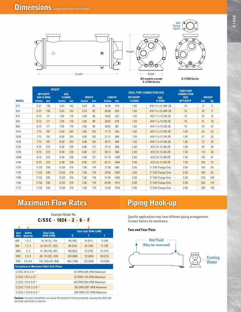
HeiGHT Tube porT npT/bspp sae sHell porT ConneCTion siZe ConneCTion sae o-rinG FlanGe widTH lenGTH npT/bspp sae siZe weiGHTmodel inches mm inches mm inches mm inches mm FlanGe o-rinG npT/bspp lbs Kg
614 5.37 136 5.63 143 3.24 82 16.38 416 1.00 #16 15/8-12 UNF-2B .75 17 8
624 5.37 136 5.63 143 3.24 82 26.38 670 1.00 #16 15/8-12 UNF-2B .75 24 11
814 6.75 171 7.00 178 3.50 89 16.62 422 1.50 #24 17/8-12 UN-2B .75 32 15
824 6.75 171 7.00 178 3.50 89 26.62 676 1.50 #24 17/8-12 UN-2B .75 41 19
836 6.75 171 7.00 178 3.50 89 38.62 981 1.50 #24 17/8-12 UN-2B .75 53 24
1014 7.75 197 8.00 203 4.00 102 17.12 435 1.50 #24 17/8-12 UN-2B 1.00 43 20
1024 7.75 197 8.00 203 4.00 102 27.12 689 1.50 #24 17/8-12 UN-2B 1.00 57 26
1036 7.75 197 8.00 203 4.00 102 39.12 994 1.50 #24 17/8-12 UN-2B 1.00 72 33
1224 8.75 222 9.38 238 5.00 127 27.13 689 2.00 #32 2½-12 UN-2B 1.50 85 39
1236 8.75 222 9.38 238 5.00 127 39.13 994 2.00 #32 2½-12 UN-2B 1.50 110 50
1248 8.75 222 9.38 238 5.00 127 51.13 1299 2.00 #32 2½-12 UN-2B 1.50 135 61
1260 8.75 222 9.38 238 5.00 127 63.13 1604 2.00 #32 2½-12 UN-2B 1.50 160 73
1724 11.59 295 12.56 319 7.00 178 27.50 699 3.00 3" SAE Flange Only 2.00 140 64
1736 11.59 295 12.56 319 7.00 178 39.50 1003 3.00 3" SAE Flange Only 2.00 180 82
1748 11.59 295 12.56 319 7.00 178 51.50 1308 3.00 3" SAE Flange Only 2.00 220 100
1760 11.59 295 12.56 319 7.00 178 63.50 1613 3.00 3" SAE Flange Only 2.00 260 118
1772 11.59 295 12.56 319 7.00 178 75.50 1918 3.00 3" SAE Flange Only 2.00 300 136
dimensions (approximate envelope)
C /
SS
C
Example Model No.
C/ssC - 1024 - 2 - 6 - F
unit baff le shell side Tube side Gpm (lpm)
size spacing Gpm (lpm) o T F
600 1.3, 3 19, 29 (72, 110) 48 (182) 24 (911) 12 (45)
800 1.7, 4 32, 69 (121, 261) 84 (318) 42 (159) 21 (79)
1000 2, 5 41, 69 (155, 261) 146 (553) 73 (276) 37 (141)
1200 2.5, 6 60, 115 (227, 435) 224 (848) 112 (424) 56 (212)
1700 3.5, 8.4 125, 253 (473, 958) 465 (1760) 232 (878) 116 (439)
exceptions to maximum shell side Flows
C/SSC-814-4-4-* 63 GPM (238 LPM) Maximum
C/SSC-1014-2-6-* 33 GPM (125 LPM) Maximum
C/SSC-1014-5-6-* 66 GPM (250 LPM) Maximum
C/SSC-1724-3.5-6-* 105 GPM (397 LPM) Maximum
C/SSC-1724-8.4-6-* 200 GPM (757 LPM) Maximum
Caution: Incorrect installation can cause this product to fail prematurely, causing the shell side and tube side fluids to intermix.
Specific applications may have different piping arrangements. Contact factory for assistance.
Two and Four pass
CoolingWater
Hot Fluid(May be reversed)
Maximum Flow Rates Piping Hook-up
Height
Length Width
SAEFlangeOption
All models except C-1700 Series
C-1700 Series

CO
MP
RE
SS
OR
S
ER
IES
Cross Reference
Air AA Series
Airtek to Thermal TransferAIR COOlEd AFTERCOOlERS
airtek Thermal Transfer
401 AA-50
402 AA-50
403 AA-80
404 AA-120
406 AA-150
407 AA-300
aKG Thermal Transfer
CC-100 AA-120
Approximate thermal, non-dimensional interchange. Core - Aluminum Fins and Copper Tubes
AKG to Thermal TransferAIR COOlEd AFTERCOOlERS
Hayden to Thermal Transfer AIR COOlEd OIl COOlERS
Hayden model Thermal series number Transfer
Temp-Toller TT-318 AOL-950 Hundred Series TT-418 AOL-1200
TT321 AOL-1600
Temp-Toller TT-324 AOL-2000 Jumbo Series TT-327 AOL-2500
TT-430 AOL-3500
Approximate thermal, non-dimensional interchange.
dunham-Bush 100 Series to Thermal Transfer AIR COOlEd OIl COOlERS
dunham-bush Thermal Transfer
DB-318 AOL-1200
DB-321 AOL-1600
DB-327 AOL-2500
DB-330 AOL-3000
DB-421 AOL-1600/AOL-3000
DB-430 AOL-3000
Approximate thermal, non-dimensional interchange.
AKG to Thermal Transfer AIR COOlEd OIl COOlERS
aKG Thermal Transfer
ACL-160 AOL-3000
ACL-250 AOL-3500
Approximate thermal, non-dimensional interchange.
Industrial AOl
Basco to Thermal Transfer AIR COOlEd OIl COOlERS
basco Thermal Transfer
1-05-1-AC-PH AOL-400
1-06-1-AC-PH AOL-725
1-07-1-AC-PH AOL-950
1-08-1-AC-PH AOL-1200
1-09-1-AC-PH AOL-1600
1-10-1-AC-PH AOL-2000
1-11-1-AC-PH AOL-2000
Approximate thermal, non-dimensional interchange.
aKG Thermal Transfer
CC-200 AHP-400
CC-450 AHP-725
CC-600 AHP-725
CC-1000 AHP-950
CC-1600 AHP-1600
CC-2000 AHP-2000
CC-2500 AHP-2500
CC-3500 AHP-3500
Approximate thermal, non-dimensional interchange.
AKG to Thermal TransferAIR COOlEd AFTERCOOlERS
Basco to Thermal TransferAIR COOlEd AFTERCOOlERS
basco Thermal Transfer
2-04-1-AC-PH AHP-400
2-05-1-AC-PH AHP-725
2-06-1-AC-PH AHP-950
2-07-1-AC-PH AHP-1200
2-08-1-AC-PH AHP-1600
2-09-1-AC-PH AHP-2000
2-10-1-AC-PH AHP-2500
2-11-1-AC-PH AHP-3000
Approximate thermal, non-dimensional interchange.
HiRoss to Thermal TransferAIR COOlEd AFTERCOOlERS
Hiross Thermal Transfer
A1203000
A1603000
A2003000
A2403000
A3203000
A4003000
A4803000
A6403000
A7503000
*Inlet air temperature 250°F (121°C) cooled to within 15°F (8.33°C) approach 100 PSIG (6.9 BAR).
AHP-725
AHP-725
AHP-725
AHP-950
AHP-1200
AHP-1600
AHP-2000
AHP-2500
AHP-3000
Basco to Thermal TransferAIR COOlEd AFTERCOOlERS
basco Thermal Transfer
2-01-1-AC-PL AA-80
2-02-1-AC-PL AA-120
2-03-1-AC-PL AA-240
Approximate thermal, non-dimensional interchange.
HiRoss to Thermal TransferAIR COOlEd AFTERCOOlERS
Hiross Thermal Transfer
A00500B0
A01000B0
A02000B0
A03000B0
A05000B0
A0803000
Inlet air temperature 250°F (121°C)cooled to within 15°F (8.33°C) approach 100 PSIG (6.9 BAR).
AA-50
AA-50
AA-120
AA-120
AA-240
AA-300
modine Thermal Transfer
AB-128
AB-129
AB-130
AB-062A
AA-80
AA-150
AA-240
AA-300
Modine to Thermal Transfer AIR COOlEd AFTERCOOlERS
Air AHP Series
Airtek to Thermal TransferAIR COOlEd AFTERCOOlERS
airtek Thermal Transfer
408 AHP-400
409 AHP-725
411 AHP-725
412 AHP-725
413 AHP-950
414 AHP-1200
416 AHP-1600
417 AHP-2000
418 AHP-2500
419 AHP-3000
421 AHP-3500
modine Thermal Transfer
AB-131
AB-132X
AB-064A
AB-066A
AB-070A
AB-074AF
AB-076AF
AHP-400
AHP-725
AHP-400
AHP-725
AHP-950
AHP-1200
AHP-2500
Modine to Thermal Transfer AIR COOlEd AFTERCOOlERS
AKG to Thermal TransferCOMBINATION OIl COOlER & AFTERCOOlERS
aKG Thermal Transfer
AOC-15 ACOC-400
AOC-30 ACOC-400
AOC-40 ACOC-725
AOC-75 ACOC-950
AOC-125 ACOC-1600
AOC-175 ACOC-2000
AOC-250 ACOC-2500
AOC-350 ACOC-3500
Approximate thermal, non-dimensional interchange.
Air ACOC Series
modine Thermal Transfer
AB-132A-2
AB-162A-5
AB-166A-5
AB-170A-5
AB-074A-5
AB-174F-10
*Maximum SCFM at 100 PSI (6.9 BAR) and 15°F (8.33°C) approach with pressure drop less than 2 PSI (.14 BAR).
ACOC-725
ACOC-950
ACOC-1200
ACOC-1600
ACOC-2000
ACOC-3000
Modine to Thermal Transfer COMBINATION OIl COOlER & AFTERCOOlERS
aKG Thermal Transfer
C-1835B BGA-35-2/1
C-13560BG BGA-60-2/1
C-70100BG BGA-100-2/1
Exact thermal, dimensional interchange.
AKG to Thermal TransferAIR COOlEd AFTERCOOlERS
Belt Guard
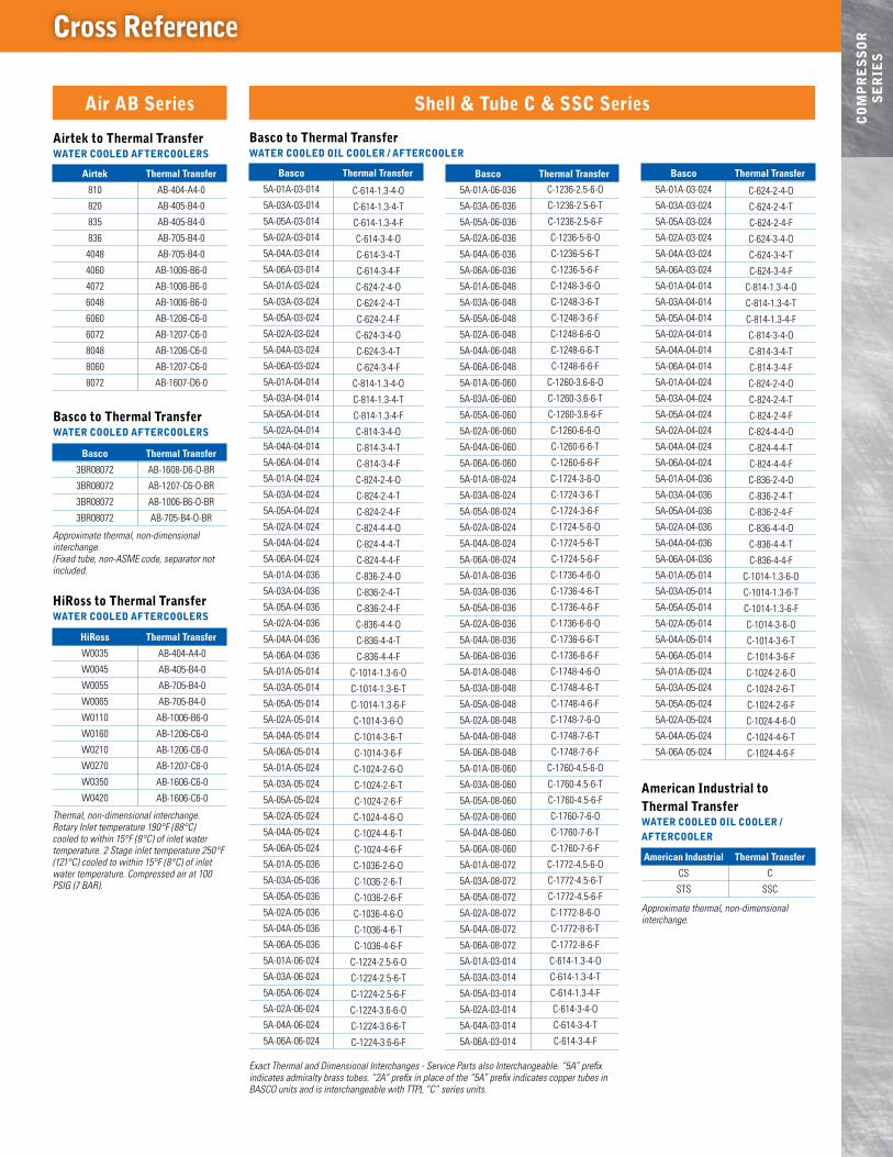
Exact Thermal and Dimensional Interchanges - Service Parts also Interchangeable. “5A” prefix indicates admiralty brass tubes. “2A” prefix in place of the “5A” prefix indicates copper tubes in BASCO units and is interchangeable with TTPL “C” series units.
CO
MP
RE
SS
OR
S
ER
IES
Cross Reference
basco Thermal Transfer
5A-01A-06-036
5A-03A-06-036
5A-05A-06-036
5A-02A-06-036
5A-04A-06-036
5A-06A-06-036
5A-01A-06-048
5A-03A-06-048
5A-05A-06-048
5A-02A-06-048
5A-04A-06-048
5A-06A-06-048
5A-01A-06-060
5A-03A-06-060
5A-05A-06-060
5A-02A-06-060
5A-04A-06-060
5A-06A-06-060
5A-01A-08-024
5A-03A-08-024
5A-05A-08-024
5A-02A-08-024
5A-04A-08-024
5A-06A-08-024
5A-01A-08-036
5A-03A-08-036
5A-05A-08-036
5A-02A-08-036
5A-04A-08-036
5A-06A-08-036
5A-01A-08-048
5A-03A-08-048
5A-05A-08-048
5A-02A-08-048
5A-04A-08-048
5A-06A-08-048
5A-01A-08-060
5A-03A-08-060
5A-05A-08-060
5A-02A-08-060
5A-04A-08-060
5A-06A-08-060
5A-01A-08-072
5A-03A-08-072
5A-05A-08-072
5A-02A-08-072
5A-04A-08-072
5A-06A-08-072
5A-01A-03-014
5A-03A-03-014
5A-05A-03-014
5A-02A-03-014
5A-04A-03-014
5A-06A-03-014
basco Thermal Transfer
5A-01A-03-014
5A-03A-03-014
5A-05A-03-014
5A-02A-03-014
5A-04A-03-014
5A-06A-03-014
5A-01A-03-024
5A-03A-03-024
5A-05A-03-024
5A-02A-03-024
5A-04A-03-024
5A-06A-03-024
5A-01A-04-014
5A-03A-04-014
5A-05A-04-014
5A-02A-04-014
5A-04A-04-014
5A-06A-04-014
5A-01A-04-024
5A-03A-04-024
5A-05A-04-024
5A-02A-04-024
5A-04A-04-024
5A-06A-04-024
5A-01A-04-036
5A-03A-04-036
5A-05A-04-036
5A-02A-04-036
5A-04A-04-036
5A-06A-04-036
5A-01A-05-014
5A-03A-05-014
5A-05A-05-014
5A-02A-05-014
5A-04A-05-014
5A-06A-05-014
5A-01A-05-024
5A-03A-05-024
5A-05A-05-024
5A-02A-05-024
5A-04A-05-024
5A-06A-05-024
5A-01A-05-036
5A-03A-05-036
5A-05A-05-036
5A-02A-05-036
5A-04A-05-036
5A-06A-05-036
5A-01A-06-024
5A-03A-06-024
5A-05A-06-024
5A-02A-06-024
5A-04A-06-024
5A-06A-06-024
Basco to Thermal TransferWATER COOlEd OIl COOlER / AFTERCOOlER
C-614-1.3-4-O
C-614-1.3-4-T
C-614-1.3-4-F
C-614-3-4-O
C-614-3-4-T
C-614-3-4-F
C-624-2-4-O
C-624-2-4-T
C-624-2-4-F
C-624-3-4-O
C-624-3-4-T
C-624-3-4-F
C-814-1.3-4-O
C-814-1.3-4-T
C-814-1.3-4-F
C-814-3-4-O
C-814-3-4-T
C-814-3-4-F
C-824-2-4-O
C-824-2-4-T
C-824-2-4-F
C-824-4-4-O
C-824-4-4-T
C-824-4-4-F
C-836-2-4-O
C-836-2-4-T
C-836-2-4-F
C-836-4-4-O
C-836-4-4-T
C-836-4-4-F
C-1014-1.3-6-O
C-1014-1.3-6-T
C-1014-1.3-6-F
C-1014-3-6-O
C-1014-3-6-T
C-1014-3-6-F
C-1024-2-6-O
C-1024-2-6-T
C-1024-2-6-F
C-1024-4-6-O
C-1024-4-6-T
C-1024-4-6-F
C-1036-2-6-O
C-1036-2-6-T
C-1036-2-6-F
C-1036-4-6-O
C-1036-4-6-T
C-1036-4-6-F
C-1224-2.5-6-O
C-1224-2.5-6-T
C-1224-2.5-6-F
C-1224-3.6-6-O
C-1224-3.6-6-T
C-1224-3.6-6-F
C-1236-2.5-6-O
C-1236-2.5-6-T
C-1236-2.5-6-F
C-1236-5-6-O
C-1236-5-6-T
C-1236-5-6-F
C-1248-3-6-O
C-1248-3-6-T
C-1248-3-6-F
C-1248-6-6-O
C-1248-6-6-T
C-1248-6-6-F
C-1260-3.6-6-O
C-1260-3.6-6-T
C-1260-3.6-6-F
C-1260-6-6-O
C-1260-6-6-T
C-1260-6-6-F
C-1724-3-6-O
C-1724-3-6-T
C-1724-3-6-F
C-1724-5-6-O
C-1724-5-6-T
C-1724-5-6-F
C-1736-4-6-O
C-1736-4-6-T
C-1736-4-6-F
C-1736-6-6-O
C-1736-6-6-T
C-1736-6-6-F
C-1748-4-6-O
C-1748-4-6-T
C-1748-4-6-F
C-1748-7-6-O
C-1748-7-6-T
C-1748-7-6-F
C-1760-4.5-6-O
C-1760-4.5-6-T
C-1760-4.5-6-F
C-1760-7-6-O
C-1760-7-6-T
C-1760-7-6-F
C-1772-4.5-6-O
C-1772-4.5-6-T
C-1772-4.5-6-F
C-1772-8-6-O
C-1772-8-6-T
C-1772-8-6-F
C-614-1.3-4-O
C-614-1.3-4-T
C-614-1.3-4-F
C-614-3-4-O
C-614-3-4-T
C-614-3-4-F
Air AB Series Shell & Tube C & SSC Series
Airtek to Thermal TransferWATER COOlEd AFTERCOOlERS
airtek Thermal Transfer
810 AB-404-A4-0
820 AB-405-B4-0
835 AB-405-B4-0
836 AB-705-B4-0
4048 AB-705-B4-0
4060 AB-1006-B6-0
4072 AB-1006-B6-0
6048 AB-1006-B6-0
6060 AB-1206-C6-0
6072 AB-1207-C6-0
8048 AB-1206-C6-0
8060 AB-1207-C6-0
8072 AB-1607-D6-0
Basco to Thermal TransferWATER COOlEd AFTERCOOlERS
basco Thermal Transfer
3BR08072 AB-1608-D6-O-BR
3BR08072 AB-1207-C6-O-BR
3BR08072 AB-1006-B6-O-BR
3BR08072 AB-705-B4-O-BR
Approximate thermal, non-dimensional interchange. (Fixed tube, non-ASME code, separator not included.
HiRoss to Thermal TransferWATER COOlEd AFTERCOOlERS
Hiross Thermal Transfer
W0035
W0045
W0055
W0065
W0110
W0160
W0210
W0270
W0350
W0420
Thermal, non-dimensional interchange. Rotary Inlet temperature 190°F (88°C) cooled to within 15°F (8°C) of inlet water temperature. 2 Stage inlet temperature 250°F (121°C) cooled to within 15°F (8°C) of inlet water temperature. Compressed air at 100 PSIG (7 BAR).
AB-404-A4-0
AB-405-B4-0
AB-705-B4-0
AB-705-B4-0
AB-1006-B6-0
AB-1206-C6-0
AB-1206-C6-0
AB-1207-C6-0
AB-1606-C6-0
AB-1606-C6-0
basco Thermal Transfer
5A-01A-03-024
5A-03A-03-024
5A-05A-03-024
5A-02A-03-024
5A-04A-03-024
5A-06A-03-024
5A-01A-04-014
5A-03A-04-014
5A-05A-04-014
5A-02A-04-014
5A-04A-04-014
5A-06A-04-014
5A-01A-04-024
5A-03A-04-024
5A-05A-04-024
5A-02A-04-024
5A-04A-04-024
5A-06A-04-024
5A-01A-04-036
5A-03A-04-036
5A-05A-04-036
5A-02A-04-036
5A-04A-04-036
5A-06A-04-036
5A-01A-05-014
5A-03A-05-014
5A-05A-05-014
5A-02A-05-014
5A-04A-05-014
5A-06A-05-014
5A-01A-05-024
5A-03A-05-024
5A-05A-05-024
5A-02A-05-024
5A-04A-05-024
5A-06A-05-024
C-624-2-4-O
C-624-2-4-T
C-624-2-4-F
C-624-3-4-O
C-624-3-4-T
C-624-3-4-F
C-814-1.3-4-O
C-814-1.3-4-T
C-814-1.3-4-F
C-814-3-4-O
C-814-3-4-T
C-814-3-4-F
C-824-2-4-O
C-824-2-4-T
C-824-2-4-F
C-824-4-4-O
C-824-4-4-T
C-824-4-4-F
C-836-2-4-O
C-836-2-4-T
C-836-2-4-F
C-836-4-4-O
C-836-4-4-T
C-836-4-4-F
C-1014-1.3-6-O
C-1014-1.3-6-T
C-1014-1.3-6-F
C-1014-3-6-O
C-1014-3-6-T
C-1014-3-6-F
C-1024-2-6-O
C-1024-2-6-T
C-1024-2-6-F
C-1024-4-6-O
C-1024-4-6-T
C-1024-4-6-F
American Industrial to Thermal TransferWATER COOlEd OIl COOlER / AFTERCOOlER
american industrial Thermal Transfer
CS C
STS SSC
Approximate thermal, non-dimensional interchange.

p psi (bar) at maximum Connection drain sCFm (Cmm) range maximum maximum Temperature size sizemodel 100 psi (7 bar) sCFm (Cmm) psi (bar) °F (°C) npT npT bowl Type drain Type
S-50 M 5-50 (.14-1.42) 0.5 (.034) 200 (14) 175 (79) 0.50 0.125 Cast Zinc Manual
S-50 AD 5-50 (.14-1.42) 0.5 (.034) 200 (14) 175 (79) 0.50 0.125 Cast Zinc Automatic with Internal Float
S-100 M 11-120 (.31-3.40) 0.5 (.034) 200 (14) 175 (79) 1.00 0.125 Cast Zinc Manual
S-100 AD 11-120 (.31-3.40) 0.5 (.034) 200 (14) 175 (79) 1.00 0.125 Cast Zinc Automatic with Internal Float
S-200 M 11-233 (.31-6.60) 0.7 (.048) 232 (16) 176 (80) 1.00 0.50 Aluminum Manual
S-300 M 60-472 (1.70-13.37) 1.0 (.069) 232 (16) 176 (80) 1.50 0.50 Aluminum Manual
S-600 M 100-742 (2.83-21.01) 1.3 (.090) 232 (16) 176 (80) 2.00 0.50 Aluminum Manual
S-1700 M 260-1700 (7.36-48.14) 1.0 (.069) 232 (16) 176 (80) 3.00 0.50 Aluminum Manual
S-2600 M 1500-3500 (42.48-99.11) 1.5 (1.03) 232 (16) 176 (80) 4.00 0.75 Carbon Steel Manual
MINIMUM OPERATING TEMPERATURE: 35°F (2°C). Specifications and dimensions subject to change without notice. Service parts available upon request.
Hose overall Fitting length approx.part Connections inside diameter length working pressure psi (bar) (each end) shipping weightnumber npT inches (mm) inches (mm) at 70°F (21°C) at 300°F (149°C) at 400°F (204°C) inches (mm) lbs (Kg)
67492 0.50 .5 (13) 10 (254) 1000 (69) 900 (62) 863 (60) 2.00 (51) 2.0 (1)
66271 1.00 1.0 (8) 12 (305) 525 (36) 460 (32) 435 (30) 1.75 (45) 2.0 (1)
66272 1.50 1.0 (25) 16 (406) 450 (31) 395 (27) 370 (26) 2.00 (51) 3.0 (1)
66273 2.00 2.0 (51) 18 (457) 400 (23) 350 (24) 330 (23) 2.00 (51) 4.5 (2)
66274 2.50 2.5 (64) 20 (508) 285 (20) 250 (17) 235 (16) 2.50 (64) 8.5 (4)
67442 3.00 3.0 (76) 22 (559) 265 (18) 230 (16) 220 (15) 3.00 (76) 12.5 (6)
66275 4.00 4.0 (102) 24 (6010) 260 (18) 225 (16) 215 (15) 4.00 (102) 14.5 (7)
AC
CE
SS
OR
IES Compressed Air Separators
S-50 and S-100 ModelsTwo Models:
n With a built-in automatic float style drain
n With a 1/8" NPT connection with manual shut off valve
Rugged cast zinc housing. Equipped with quick disconnect bowls for easy service.
S-200 thru S-1700 ModelsFour models to fit most applications. Unique high efficiency design provides wide SCFM capacity range without loss in performance. Sturdy, lightweight aluminum construction for long dependable service. NPT threaded drain connection for installation of an electronic, manual or automatic float style drain. Low differential pressure at maximum flow ratings. Externally and internally epoxy painted for maximum corrosion protection.
Model S-2600-M (Manual drain NPT connection)
Model S-2600-4F (Manual drain ASME flange connection)
1500 thru 3500 SCFM (42.48 through 99.11 SCMM) capacity. Consult factory for details on larger models thru 16,000 SCFM (45.31 SCMM).
Designed to isolate damaging vibration, dampen noise and absorb thermal expansion from pumps and compressors to other related equipment. Hose is of corrosion resistant type 304 stainless steel. Connectors are carbon steel schedule 40 external NPT with hex nut attachments on both ends for easy installation. Couplings are welded to assure dependable leak free operation.
Maximum operating temperature 1500°F (816°C). Other sizes and lengths available.
Modulating Water Valves and 3-Way Thermostatic Valves available. See catalog for details.
Flexible Connectors

INS
TA
ll
AT
IONRecommended Typical Installation
Electronic Floator Manual Drain
Aftercooler
Cooling Water Out
Shut-Off Valve
Cooling Water In
To Receiver or Dryer
To Drain
MoistureSeparator
Strainer
From Compressor
From Compressor
Aftercooler
To Drain
To Receiver or Dryer
MoistureSeparator
Shut-Off Valve
Strainer
Electronic Floator Manual Drain
Air Cooled Equipment
Electronic Floator Manual Drain
Aftercooler
Cooling Water Out
Shut-Off Valve
Cooling Water In
To Receiver or Dryer
To Drain
MoistureSeparator
Strainer
From Compressor
From Compressor
Aftercooler
To Drain
To Receiver or Dryer
MoistureSeparator
Shut-Off Valve
Strainer
Electronic Floator Manual Drain
Water Cooled Equipment

TE
CH
NIC
Al
INF
OR
MA
TIO
N Technical Information
Recommended Typical Installation
n Support piping as needed. Flexible connectors must be properly installed to validate warranty.
n Coolers should not operate in ambient temperatures below 35°F (1°C). Consult factory for recommendations.
n The fan cannot be cycled.
n AHP coolers operated outdoors must be protected from weather. Consult factory for recommendations.
n If ductwork or additional static resistance is added to the cooler airstream, an auxiliary air mover may be required.
Maintenance n Periodic cleaning of the fins with compressed air is needed to remove the
accumulation of dirt and dust.
n Check the automatic drain on the separator (not included) periodically.
n If the inside of the tubes need to be cleaned of oil and carbon, use a chlorinated solvent. Do not use strong solvents. Do not use acids or caustic cleaners.
HO
W T
O O
Rd
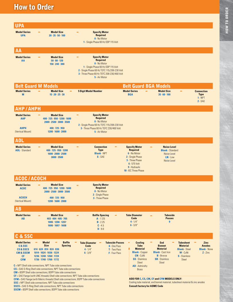
ERHow to Order
UPAmodel series
upamodel size
20 · 35 · 50 · 100
C & SSCmodel series
C & ssC Cs & ssCs
Cm & ssCmCF
CFm
model size
Tube diameterCode
4 - 1/4”6 - 3/8”
Tubeside passes0 - One PassT - Two PassF - Four Pass
– baff lespacing
CoolingTube
material blank - Copper
Cn - CuNiss - Stainless
Steelad - Admiralty
Brass
endbonnet
material blank - Cast Iron
b - Bronzesb - Stainless
Steel
Tubesheetmaterial
blank - Steelw - CuNi
s - Stainless Steel
Zincanodes
blank - NoneZ - Zinc
– – – –––-
C = NPT Shell side connections; NPT Tube side connectionsCs = SAE O-Ring Shell side connections; NPT Tube side connectionsCm = BSPP Shell side connections; BSPP Tube side connectionsCF = SAE Flange (with UNC threads) Shell side connections; NPT Tube side connectionsCFm = SAE Flange (with Metric threads) Shell side connections; BSPP Tube side connectionsssC = NPT Shell side connections; NPT Tube side connectionsssCs = SAE O-Ring Shell side connections; NPT Tube side connectionsssCm = BSPP Shell side connections; BSPP Tube side connections
add For C, Cs, Cm, CF and CFm models only:Cooling tube material, end bonnet material, tubesheet material & zinc anodesConsult factory for asme Code
AAmodel series
aa model size50 · 80 · 120
150 · 240 · 300
specify motorrequired
0 - No Motor1 - Single Phase 60 Hz ODP 115 Volt
2 - Single Phase 60 Hz TEFC 115/208-230 Volt3 - Three Phase 60 Hz TEFC 208-230/460 Volt
5 - Air Motor
AHP / AHPHmodel series
aHp
aHpH(Vertical Mount)
model size400 · 725 · 950 · 1200 · 1600
2000 · 2500 · 3000 · 3500
400 · 725 · 950 1200 · 1600 · 2000
specify motorrequired
0 - No Motor2 - Single Phase 60 Hz TEFC 115/208-230 Volt
3 - Three Phase 60 Hz TEFC 230/460 Volt5 - Air Motor
ACOC / ACOCHmodel series
aCoC
aCoCH(Vertical Mount)
model size400 · 725 · 950 · 1200 · 1600
2000 · 2500 · 3000 · 3500
400 · 725 · 950 1200 · 1600 · 2000
specify motorrequired
0 - No Motor 2 - Single Phase3 - Three Phase
ABmodel series
ab model size
403 · 404 · 405 · 705 1006 · 1206 · 1207 1606 · 1607 · 1608
baff le spacinga - 1.125b - 2.25C - 4.5d - 9.0
Tube diameterCode
4 - 1/4”6 - 3/8”
Tubeside passes
0
– – – –
AOlConnection
Typeblank - NPT
s - SAE
model seriesaol - Standard
model size400 · 725 · 950 · 1200
1600 · 2000 · 2500 3000 · 3500
specify motorrequired
0 - No Motor2 - Single Phase3 - Three Phase
6 - 575 Volt9 - Hydraulic
18 - IEC Three Phase
noise levelblank - Standard
Noise Level ln - Low
Noise Level
– – – –
Belt Guard M Models Belt Guard BGA Modelsmodel series
mmodel size
15 · 20 · 25 · 30–
– –
– –
– –
–
614 · 624 · 814 · 824 · 8361014 · 1024 · 1036 · 12241236 · 1248 · 1260 · 17241736 · 1748 · 1760 · 1772
specify motorrequired
0 - No Motor1 - Single Phase 60 Hz ODP 115 Volt
–
model seriesbGa
model size35 · 60 · 100
– ConnectionType
1 - NPT2 - SAE
–5 digit model number–
5215 21st Street Racine, Wisconsin 53406-5096
Tel: (262) 554-8330 Fax: (262) 554-8536
e-mail: [email protected]
websiTe: www.thermaltransfer.com
Compressed Air AftercoolersAftercoolers are heat exchangers that cool the discharge from a compressor. The media used is air & water and is the most effective way to segregate the moisture and compressed air. Aftercoolers control the amount of water vapor in a compressed air system via condensing the water vapor into a liquid form. In nearly all industries with manufacturing or service equipment, liquid water can cause permanent damage when using compressed air.
An aftercooler is required to ensure the proper function of pneumatic or air handling devices. The two methods utilized are either air cooled or water cooled aftercooling.
Typically aftercoolers are integrated into the OE compressor or may stand alone and located somewhere downstream of the compressor.
Moisture separators and drain valves are mounted into a pipeline fitted with water cooled aftercoolers or a heat exchanger. They extract the majority of water from the compressed air as it passes through the piped components. The moisture separator spins the fluid by using centrifugal force to separate out the moisture and solids from the compressed air. The water is allowed to exit via a bottom drain. An air cooled heat exchanger uses available ambient air to cool the hot compressed air. Most air cooled heat exchangers use a fan that produces forced air. The fan is driven by an air or electric motor which forces the ambient air over the cooler, removing the heat from the compressed air.
Due to mechanical friction created from moving parts, compressors generate significant heat. To promote long component life and efficient operation, all moving parts must be lubricated. Thermal Transfer Products compressor coolers supply cooled oil to compressor operation, including all bearing and friction points. When heat circulates throughout compressor internals, heat is transferred to the oil and must subsequently be cooled via a heat exchanger.
Air Cooled AftercoolersThermal Transfer Products models of air cooled aftercoolers provide economical cooling by utilizing available ambient air to cool the hot compressed air from an air compressor. When properly sized, an aftercooler can remove up to 60% of the water in compressor air.
Owing to the compressor type, discharge air is approximately 150-350˚F (66-177˚C). During the cooling of the compressed air, nearly 60% of the water vapor present will condense into liquid water. A line installed separator will immediately remove the water from the system. Air cooled aftercoolers, when applied properly, can cool the hot compressed air between 5-20˚F (3-11˚C) of the available ambient air temperature. Normally wasted heat can be reclaimed and recirculated by the aftercooler.
Water Cooled Aftercoolers Thermal Transfer water cooled aftercoolers, when combined with a water separator, are a significant means of removing unwanted water moisture from compressed air. Field studies prove that a properly sized and installed aftercooler and liquid separator will effectively maintain worry free operation of compressed air equipment. When the downstream compressed air line temperature is lowered by applying a correctly sized water cooled aftercooler, more than 70% of the entrained water vapor will condense to liquid form. This liquid is easily removed by a moisture separator.