Embed Size (px)
Citation preview

Matrx145 Mid County DriveOrchard Park, New York 14127716-662-6650
800-847-1000888-279-1260
Toll-Free:Technical Support:Fax:E-mail:
10496400 Rev. C
OL Series AirMaxOil-less Compressor
Models: OL-3, OL-7, OL-10
Installation & Operation
™


Table of Contents
Section 1 About AirMax OL ..............................1
Section 2 Specifications & Model Selection ...3
Section 3 Installation ........................................4
Section 4 Operation & Maintenance ........... 7
Section 5 Troubleshooting .......................... 9
Section 6 ................ 11
Section 7 Wiring Diagrams .......................... 12
Section 8 Service & Warranty ...................... 15
1.1 Compressor Features1.2 Compressor Flow Diagram
2.1 Compressor Specifications2.2 Unit Selection Guide
3.1 Site Selection3.2 Compressor Setup3.3 Electrical Connections3.4 Piping3.5 Fresh Air Intake3.6 Installation Checkout
4.1 Operation4.2 Maintenance
Connections
Replacement Parts ......
Safety Warnings and Important Information
WARNING: Always disconnect electrical power tocompressor before servicing.
WARNING: To prevent injury from high pressure air,never remove coalescing filter bowl or any otherpressurized component until purge cycle has endedand system has been relieved of air pressure byopening service drain valve.
WARNING: Compressor heads are extremely hotduring operation. To avoid burning yourself, allowunit to cool before servicing.
WARNING: Compressor motors are thermallyprotected with an automatic reset and may restartwithout warning.
WARNING: Compressor motors are controlled by apressure switch and will have line voltage applied tothem whenever the tank pressure is below 80 PSI.The compressor may start without warning.
IMPORTANT: Installations must be made to all localcodes.
CAUTION: Adequate line voltage is essential toproper compressor operation. Voltages outside thespecified range in Section 2.1 require a buck or boosttransformer. Otherwise, failure to start, circuit breakertripping, overheating and compressor damage mayoccur.
CAUTION: Excessive circuit lengths should beavoided to reduce voltage drop during compressoroperation. Voltage measurements should be takenwhile the compressor is running. A static voltagereading is not a true indication of voltage supplyduring operation.
CAUTION: Compressors installed outdoors must beprotected from rain, snow, direct sunlight and excessdust. Temperature limits and ventilationrecommendations must also be followed.
CAUTION: On OL-7 and OL-10 units, always keepboth service switches in the ON position. Never runthe compressor with one head turned OFF except forshort periods of time while one head is notoperational.
CAUTION: Never turn a compressor head ON whileother head is running as the heads will not start underback pressure. Allow the pressure switch to shut offthe compressor at 100 PSI or disconnect thecompressor main power supply to relieveline pressure through the solenoid valve.
completely
CAUTION: To avoid compressor overheating andthermal shutdowns, the installation site must beproperly ventilated and, if necessary, air conditionedto prevent ambient temperatures from exceeding104°F/40°C.

SECTION 1.0 ABOUT AIRMAX OL-SERIES COMPRESSORS
1.1 Compressor Features
See the Matrx DentalEquipment Catalog for additional information) Thesecompressors are available in 3-, 7- and 10-userconfigurations.
AirMax Oil-less compressors combine high-performance design with rugged, trouble-freeconstruction to provide high quality compresseddental air. Built with high-reliability oil-less pistoncompressor heads, they feature an integral desiccantdrying system and in-line filter to ensure delivery ofclean, dry air that is free of water, oil and othercontaminants that could compromise dentalprocedures and handpiece operation. Air is stored in
an ASME-certified tank. All units are also equippedwith a low voltage relay to enable operation from aremote location. Optional sound-reducing covers areavailable for all configurations (
.
Figure 1 identifies AirMax OL-Series components thatare discussed in the operation and installationsections of this manual.
Figure 1. AirMax Oil-less Compressor Features (AirMax OL-7 shown)
1
REMOTEAIR INTAKE
CONNECTION
AIR SAFETY VALVE
OL-7 with optional Sound Cover
OIL-LESSCOMPRESSORHEADS
REGENERATIVEDESICCANTDRYER
PRESSURE GAUGE
MOISTURE INDICATOR
AIR RECEIVER TANK
SERVICESWITCHES
(INSIDECOVER)
DRAIN VALVE
OUTLETVALVE

2
Figure 2. AirMax OL Series Flow Diagram
ABOUT AIRMAX OL-SERIES COMPRESSORS cont.
COMPRESSED AIRTO OPERATORIES
AIR FLOW(MOTOR “ON”)
AIR FLOW DURINGPURGE CYCLE(MOTOR “OFF”)
CH
EC
KV
ALV
E
PURGE AIR TANK
AIR RECEIVER TANK
DE
SIC
CA
NT
TA
NK
AFTERCOOLER
COALESCINGFILTER
SOLENOID VALVE-CLOSED (ENERGIZED) WHEN MOTOR IS “ON”-OPEN WHEN MOTOR IS “OFF”
CHECK VALVEWITH ORIFICEFOR AIR PURGE
1.2 Compressor Flow Diagram
for several seconds
During the operating cycle, compressed air flows fromthe compressor head through an aftercooler (a coilwrapped around the purge tank). The cooled air thenpasses through a coalescing filter that removesparticulates. From the filter, the air streams flows upinto the desiccant tank, through desiccant beadswhich extract moisture. Dry compressed air is nowstored in the main air receiver tank, as well as thepurge tank. Apressure switch monitors air pressure inthe receiver and shuts off the compressor motor when
pressure reaches 100 psi. It restarts the motor whenpressure drops below 80 psi.
During the purge cycle, the compressor motor shutsoff and the solenoid valve opens, releasing a smallburst of air. After this, a slow stream of air (stored in thepurge tank) continues to flowthrough the desiccant tank, coalescing filter, and outthrough the solenoid. This cycle removes moisturebuilt up in the desiccant tank, as well as particulatesfrom the coalesing filter.
SECTION 2.0 SPECIFICATIONS & MODEL SELECTION
3
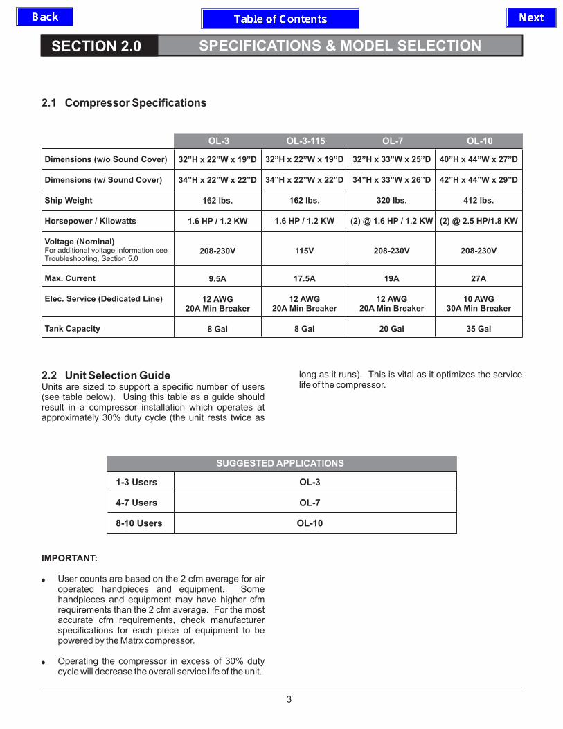
2.2 Unit Selection Guide
Using this table as a guide shouldresult in a compressor installation which operates atapproximately 30% duty cycle (the unit rests twice as
long as it runs). This is vital as it optimizes the servicelife of the compressor.Units are sized to support a specific number of users
(see table below).
2.1 Compressor Specifications
OL-3 OL-3-115 OL-7 OL-10
Dimensions (w/o Sound Cover)
Dimensions (w/ Sound Cover)
Ship Weight
Horsepower / Kilowatts
Voltage (Nominal)
Max. Current
Elec. Service (Dedicated Line)
Tank Capacity
For additional voltage information seeTroubleshooting, Section 5.0
32”H x 22”W x 19”D
34”H x 22”W x 22”D
162 lbs.
1.6 HP / 1.2 KW
208-230V
9.5A
12 AWG20A Min Breaker
8 Gal
32”H x 22”W x 19”D
34”H x 22”W x 22”D
162 lbs.
1.6 HP / 1.2 KW
115V
17.5A
12 AWG20A Min Breaker
8 Gal
32”H x 33”W x 25”D
34”H x 33”W x 26”D
320 lbs.
(2) @ 1.6 HP / 1.2 KW
208-230V
19A
12 AWG20A Min Breaker
20 Gal
40”H x 44”W x 27”D
42”H x 44”W x 29”D
412 lbs.
(2) @ 2.5 HP/1.8 KW
208-230V
27A
10 AWG30A Min Breaker
35 Gal
SUGGESTED APPLICATIONS
1-3 Users
4-7 Users
8-10 Users
OL-3
OL-7
OL-10
IMPORTANT:
User counts are based on the 2 cfm average for airoperated handpieces and equipment. Somehandpieces and equipment may have higher cfmrequirements than the 2 cfm average. For the mostaccurate cfm requirements, check manufacturerspecifications for each piece of equipment to bepowered by the Matrx compressor.
Operating the compressor in excess of 30% dutycycle will decrease the overall service life of the unit.
�
�
SECTION 3.0 INSTALLATION
3.1 Site Selection
3.2 Compressor Setup
Note: Installations must be made to local codesby licensed plumbers and electricians.
Temperature:
Service Clearance:
Piping:
Fresh Air Intake:
Electrical Power: s
Remote Control Panel (not included):
Select an installation site that meets the followingrequirements:
Site must have an ambienttemperature range of 40° to 104° F (4° to 40° C).Provide additional cooling or heating if necessaryto maintain this temperature range.
30 inches clearance shouldbe provided in front of the compressor for serviceprocedures. 12 inches clearance should beprovided around remaining sides of thecompressor.
The installation site will also require the followingutilities to be installed:
Contractor or plumber to supply piping forpressurized air from compressor to theoperatories. See “Piping Connections”, section3.4.
Per NFPA code 99C,compressor air intake shall not be within thevicinity of open exhaust from a dental vacuumpump. An air intake kit is included to meet thiscode by bringing in fresh air from an exteriorlocation. See “Fresh Air Intake Installation”,section 3.5.
A dedicated circuit per ection2.1 is required for operation. See “ElectricalConnections”, section 3.3.
A MatrxCP-Series control panel is recommended for on-off switching of the system. The contractor orlicensed electrician installs 3-conductor jacketedwire (provided) from the electrical box on thecompressor to the remote control panel. See theMatrx Dental Equipment Catalog for additionalinformation, and “Electrical Connections”, section3.3.
1. Remove compressor from pallet.
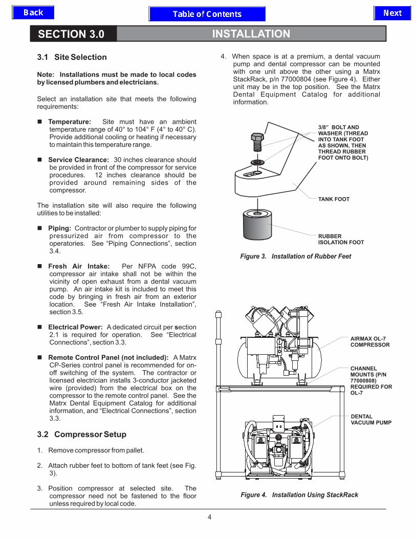
2. Attach rubber feet to bottom of tank feet (see Fig.3).
3. Position compressor at selected site. Thecompressor need not be fastened to the floorunless required by local code.
4. When space is at a premium, a dental vacuumpump and dental compressor can be mountedwith one unit above the other using a MatrxStackRack, p/n 77000804 (see Figure 4). Eitherunit may be in the top position. See the MatrxDental Equipment Catalog for additionalinformation.
�
�
�
�
�
�
4
Figure 4. Installation Using StackRack
CHANNELMOUNTS (P/N77000808)REQUIRED FOROL-7
OFF OFF
30
25
VAC
VAC
IN HGIN HG
76
70
CM HGCM HG
50
60
10
30
20
40
20
15
10
5
AIRMAX OL-7COMPRESSOR
DENTALVACUUM PUMP
Figure 3. Installation of Rubber Feet
TANK FOOT
RUBBERISOLATION FOOT
3/8” BOLT ANDWASHER (THREADINTO TANK FOOTAS SHOWN, THENTHREAD RUBBERFOOT ONTO BOLT)

5
INSTALLATION cont.
CONTROLPANEL
SWITCH
RED
BLUEWHT
RED
BLUEWHT
Important!For installations remote control panels,strip ends of red and white wires and connectwith wire nut as shown. Compressor will notoperate if these leads are disconnected.
without
CONNECTWIRES RED
BLUE
WHT
18/3 JACKETEDBELL WIRE
MODEL OL-3, 7, 10 (220 V) : RED (HOT)
MODEL-OR-
OL-3-115 (115 V) ONLY: WHITE (NEUTRAL)
CONNECT TOELECTRICAL
SERVICE(DEDICATED
LINE) - SEESECTION 2.1
7 FT. FLEXIBLEHOOKUP LINE(SUPPLIED)
REMOTE CONTROLPANEL
LOWVOLTAGECONTROL
LEADS
6-FOOT FLEXIBLEAIR HOSE WITH 1/2”NPT CONNECTIONS
-CONNECT TOOPERATORY LINE
3.3 Electrical Connections
3.4 Piping ConnectionsAirMax OL-Series Compressors require the followingelectrical connections as shown in Figure 5:
Connect power from a dedicated branch circuit tothe compressor power hookup leads as shownbelow. See section 2.1 for power requirements.
Connect low voltage control wires. If compressoris to be operated remotely, connect 18/3 jacketedbell wire from the compressor low voltage leads toa Matrx CP-Series control panel. For installations
without remote control panel, connect red andwhite low voltage leads together as shown.
Install air distribution line (1/2” copper tubing, TypeK or L) from operatories to the compressor.
Connect the 1/2” MNPT swivel end of the 6-footflexible hookup hose to the compressor ball valve,and the opposite 1/2” MNPT end to the operatoryline.
�
�
�
�
Figure 5. AirMax Electrical and Piping Connections
GROUND(GREEN)
BLACK(HOT)

6
INSTALLATION cont.
3.5 FreshAir Intake
�
�
Connect 1” flexible PVC hose (supplied) to a 1”PVC pipe (provided by contractor) leading to anexternal fresh air source.
Connect opposite end of hose to fresh air intakemanifold at back of compressor, using supplied 1”slip to hose barb connector (straight or elbow).
3.6 Installation Checkout
Perform initial checkout testing as follows:
Check that compressor head filter boots are fullyseated and that air intake hoses are securelyconnected (see Figure 7).
Check that drain valve at bottom of tank is closed.
Open outlet ball valve to operatories.
Turn on power to compressor. As compressorpumps up, observe pressure gauge. Verify thatcompressor shuts off at 100 PSI.
Open drain valve at bottom of tank to bleed air fromsystem. Verify that compressor restarts at 80 PSI.Close drain valve.
Check system for leaks (see Troubleshooting,Section 5.0, for leak test procedure).
�
�
�
�
�
�
1” PVC VENTTO OUTSIDEPROVIDED BYCONTRACTOR
RAIN COVERPROVIDED BYCONTRACTOR
1” PVC HOSE
FRESH AIRINTAKEMANIFOLD
(BACK OF COMPRESSOR)
Figure 6. Fresh Air Intake

4.1 Operation
4.2 Maintenance
Airmax OL-Series compressors are started bypressing the “AIR” switch on the remote control panel,or, for units without remote control panel, by switchingon the main power circuit to the compressor.
Note: Units with two compressor motors must haveboth motors operating simultaneously during normaloperation. Always keep both service switches in the“ON” position.
Replace the air intake filters annually, or more often ina dusty environment. When installing the new filter,ensure that the filter is inserted into the rubberfilter boot, then press into place in compressor head.See Figure 7.
Replace the coalescing filter element annually, ormore often in a dusty environment. Disconnect powerfrom compressor before replacing. See figure 8.
fully
SECTION 4.0 OPERATION & MAINTENANCE
7
REPLACE COALESCING FILTER ELEMENT
Figure 8. Coalescing Filter
Figure 7. Air Intake Filters
COALESCINGFILTERELEMENT
REPLACE AIR INTAKE FILTERS
AIR INTAKE FILTERS(INSERT WITH HOLEFACING OUT ASSHOWN)
GASKET
FILTER BOOT

OPERATION AND MAINTENANCE cont.
8
Annually, open the receiver tank drain to remove anyaccumulation of water. Drain more frequently in veryhumid environments. Close the drain valve afterwater is purged. (See Figure 9).
Annually, test the air safety valve by p
If the valve does not operate freely, the airsafety valve may not protect the system from anoverpressure condition, and must be replaced.
Periodically check the moisture indicatorUnder normal operating conditions the indicator isblue. If the indicator turns pink, there is a high level ofmoisture in the tank. See “Troubleshooting”, section5.0.
Warning:
ulling the testring of the air safety valve. The valve stem should beable to move freely. (See Figure 10).
(Figure 10).
DRAIN WATER BUILDUP IN TANK
Figure 10. Manifold Block
SERVICE DRAINVALVE
Figure 9. Service Drain Valve at Base of Tank
TEST AIR SAFETY VALVE
CHECK MOISTURE INDICATOR
AIR SAFETYVALVE
MOISTUREINDICATOR
SECTION 5.0 TROUBLESHOOTING
9
WARNING:
CAUTION:
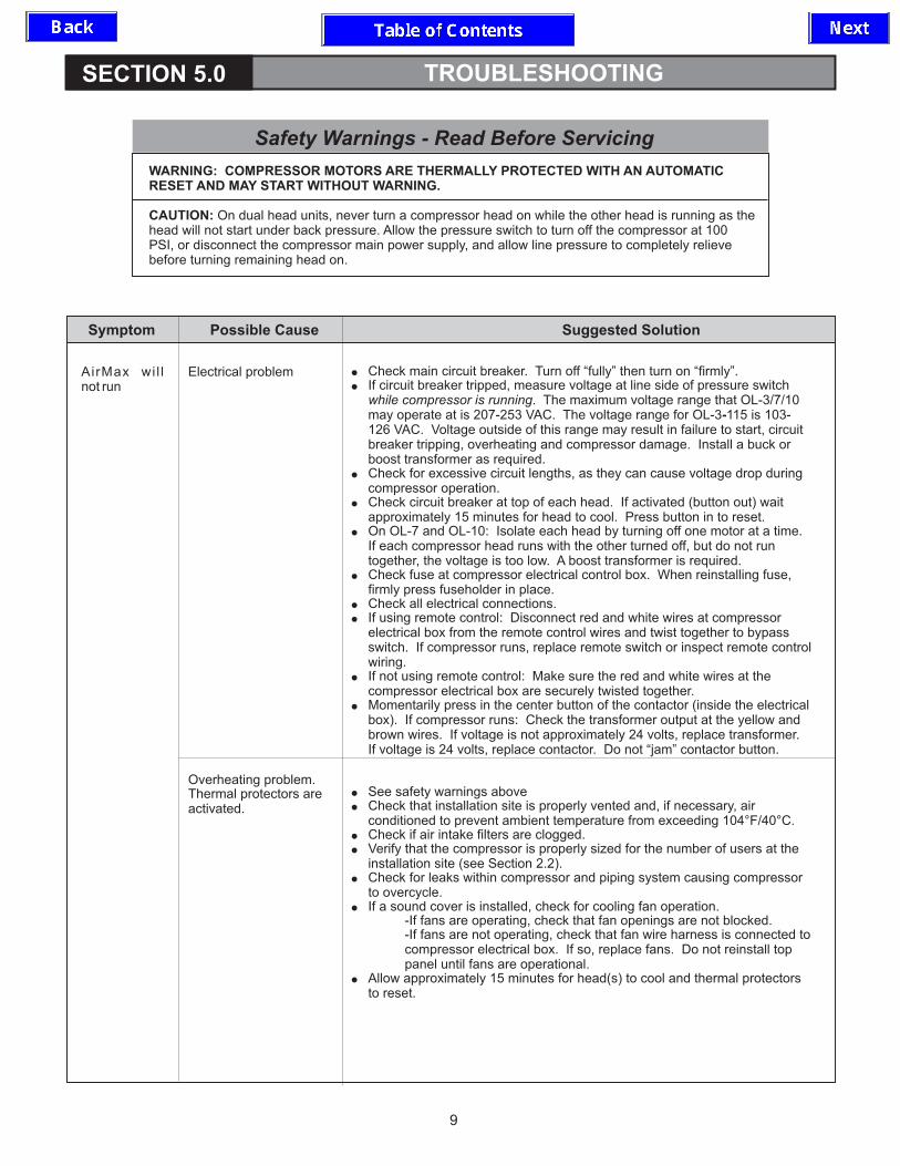
COMPRESSOR MOTORS ARE THERMALLY PROTECTED WITH AN AUTOMATICRESET AND MAY START WITHOUT WARNING.
On dual head units, never turn a compressor head on while the other head is running as thehead will not start under back pressure. Allow the pressure switch to turn off the compressor at 100PSI, or disconnect the compressor main power supply, and allow line pressure to completely relievebefore turning remaining head on.
AirMax wi l lnot run
Electrical problem
Overheating problem.Thermal protectors areactivated.
�
�
�
�
�
�
�
�
�
�
�
�
�
�
�
�
�
Check main circuit breaker. Turn off “fully” then turn on “firmly”.If circuit breaker tripped, measure voltage at line side of pressure switch
. The maximum voltage range that OL-3/7/10may operate at is 207-253 VAC. The voltage range for OL-3 115 is 103-126 VAC. Voltage outside of this range may result in failure to start, circuitbreaker tripping, overheating and compressor damage. Install a buck orboost transformer as required.Check for excessive circuit lengths, as they can cause voltage drop duringcompressor operation.Check circuit breaker at top of each head. If activated (button out) waitapproximately 15 minutes for head to cool. Press button in to reset.On OL-7 and OL-10: Isolate each head by turning off one motor at a time.If each compressor head runs with the other turned off, but do not runtogether, the voltage is too low. A boost transformer is required.Check fuse at compressor electrical control box. When reinstalling fuse,firmly press fuseholder in place.Check all electrical connections.If using remote control: Disconnect red and white wires at compressorelectrical box from the remote control wires and twist together to bypassswitch. If compressor runs, replace remote switch or inspect remote controlwiring.If not using remote control: Make sure the red and white wires at thecompressor electrical box are securely twisted together.Momentarily press in the center button of the contactor (inside the electricalbox). If compressor runs: Check the transformer output at the yellow andbrown wires. If voltage is not approximately 24 volts, replace transformer.If voltage is 24 volts, replace contactor. Do not “jam” contactor button.
See safety warnings aboveCheck that installation site is properly vented and, if necessary, airconditioned to prevent ambient temperature from exceeding 104°F/40°C.Check if air intake filters are clogged.Verify that the compressor is properly sized for the number of users at theinstallation site (see Section 2.2).Check for leaks within compressor and piping system causing compressorto overcycle.If a sound cover is installed, check for cooling fan operation.
-If fans are operating, check that fan openings are not blocked.-If fans are not operating, check that fan wire harness is connected tocompressor electrical box. If so, replace fans. Do not reinstall toppanel until fans are operational.
Allow approximately 15 minutes for head(s) to cool and thermal protectorsto reset.
while compressor is running-
Symptom Possible Cause Suggested Solution
Safety Warnings - Read Before Servicing
10
TROUBLESHOOTING cont.
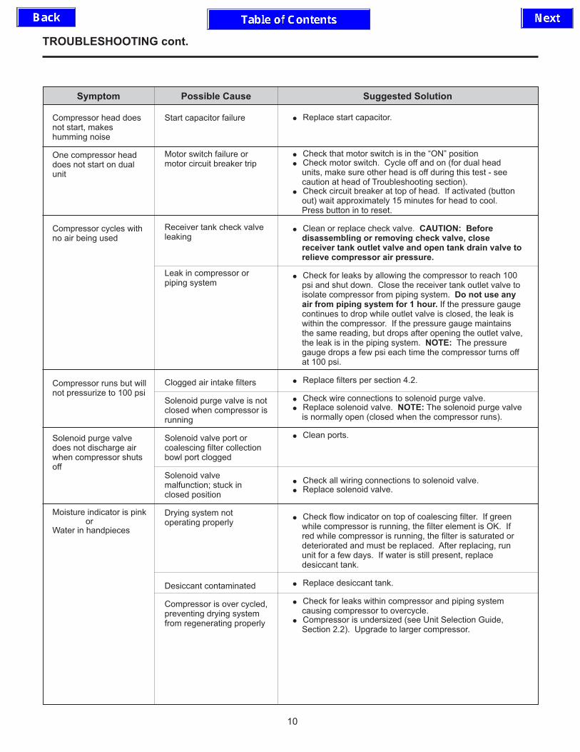
Compressor head doesnot start, makeshumming noise
One compressor headdoes not start on dualunit
Compressor cycles withno air being used
Compressor runs but willnot pressurize to 100 psi
Solenoid purge valvedoes not discharge airwhen compressor shutsoff
Moisture indicator is pinkor
Water in handpieces
Start capacitor failure
Motor switch failure ormotor circuit breaker trip
Receiver tank check valveleaking
Leak in compressor orpiping system
Clogged air intake filters
Solenoid purge valve is notclosed when compressor isrunning
Solenoid valve port orcoalescing filter collectionbowl port clogged
Solenoid valvemalfunction; stuck inclosed position
Drying system notoperating properly
Desiccant contaminated
Compressor is over cycled,preventing drying systemfrom regenerating properly
�
�
�
�
�
�
�
�
�
�
�
�
�
�
�
�
Replace start capacitor.
Check that motor switch is in the “ON” positionCheck motor switch. Cycle off and on (for dual headunits, make sure other head is off during this test - seecaution at head of Troubleshooting section).Check circuit breaker at top of head. If activated (buttonout) wait approximately 15 minutes for head to cool.Press button in to reset.
Clean or replace check valve.
Check for leaks by allowing the compressor to reach 100psi and shut down. Close the receiver tank outlet valve toisolate compressor from piping system.
If the pressure gaugecontinues to drop while outlet valve is closed, the leak iswithin the compressor. If the pressure gauge maintainsthe same reading, but drops after opening the outlet valve,the leak is in the piping system. The pressuregauge drops a few psi each time the compressor turns offat 100 psi.
Replace filters per section 4.2.
Check wire connections to solenoid purge valve.Replace solenoid valve. The solenoid purge valveis normally open (closed when the compressor runs).
Clean ports.
Check all wiring connections to solenoid valve.Replace solenoid valve.
Check flow indicator on top of coalescing filter. If greenwhile compressor is running, the filter element is OK. Ifred while compressor is running, the filter is saturated ordeteriorated and must be replaced. After replacing, rununit for a few days. If water is still present, replacedesiccant tank.
Replace desiccant tank.
Check for leaks within compressor and piping systemcausing compressor to overcycle.Compressor is undersized (see Unit Selection Guide,Section 2.2). Upgrade to larger compressor.
CAUTION: Beforedisassembling or removing check valve, closereceiver tank outlet valve and open tank drain valve torelieve compressor air pressure.
Do not use anyair from piping system for 1 hour.
NOTE:
NOTE:
Symptom Possible Cause Suggested Solution

SECTION 6.0 REPLACEMENT PARTS
11
1
The AirMax OL Series Compressor parts identified below may be ordered by an authorized dealer from Matrxby contacting: Customer Service, 800-847-1000 or 716-662-6650
OL-3-115One 2-Cylinder
Head; 115V 60HZp/n 77000970
OL-3One 2-Cylinder
Head; 220V 60HZp/n 77000971
OL-7Two 2-Cylinder
Heads; 220V 60HZp/n 77000972
OL-10Two 3-Cylinder
Heads; 220V 60HZp/n 77000973
Air Filter Element
Pressure Switch
Contactor
Transformer
Desiccant Tank
Solenoid Valve Assembly
Compressor Head
Circuit Breaker
Sound Reducing Cover
Motor Switch
Fuse, 3/4 Amp Slow Blow
Air Intake Hose
Humidity Indicator
Receiver Tank Check Valve
Coalescing Filter Element
Outlet Valve, 1/2” NPT
Drain Valve, 1/4” NPT
Air Safety Valve
Pressure Gauge
Rubber Isolation Foot
High Pressure Hose, 72” L
Coalescing Filter Assembly
77001541 (2 Req’d)
77005143
62899901
77001451
77000564
77001571
77001549
77001564
77000984
77001541 (2 Req’d)
77005143
62899901
77001451
77000564
77001572
77001544
77001562
77000979
77001130
77001402
65962201 (specify length in inches)
77005140
65959100
77005010
77005005
10378600
61301100
77005020
77005012
65962901
77001391
77001541 (4 Req’d)
77005143
62899902
77001452
77000565
77001570
77001544
77001562
77000980
77001541 (6 Req’d)
77005144
62899902
77001452
77000566
77001570
77001545
77001563
77000981
Part DescriptionItem
1
2
3
4
5
6
7
8
NS
9
10
11
12
13
14
15
16
17
18
19
20
NS
2
3
4
5
6
8
7
9
10
11
12
13
14 15
16
17
18
19

SECTION 7.0 WIRING DIAGRAMS
12
Figure 11. OL-3 (220 VAC) Wiring Diagram
REMOTESWITCH
RED
T1BLK3/4 A
L2
L1
TERMINALSTRIPELECTRICAL
BOX
BLK
BLK
RED
A2
L3
T3
CONTACTOR
RED
T1
T2
L1
A1
L2 13
14
A2
XF
MRBRN
RE
D
BLK
BLK
YEL
RED
BLK
PRESSURESWITCH
L1
DEDICATEDSUPPLY220 VAC
BLK
FANRECEPTACLE
GRN/YEL
BLK
RED4
2
3
RED
WHT
BLU
BRN
FUSE
RE
D
RE
D
THERMALSWITCH
THERMALSWITCH
GRN
GRN
RE
D
BL
K
L2
T2
RED
BLK
START CAPACITOR
GR
N
WH
T
U1
BL
K
V1 W1
BRN
W2 U2 V2
BLU
GRN
1
CIRCUITBREAKER
BL
U
BL
U
2
11A
220VSOLENOIDVALVE
RED
RED
MOTOR
RED
GRN
BLK L1
L2
VOLTAGE SUPPLY TO THIS UNIT IS NOT FIELDINTERCHANGEABLE. DO NOT MOVE JUMPERLOCATIONS, DAMAGE TO COMPRESSORCOMPONENTS WILL OCCUR
CAUTION

13
WIRING DIAGRAMS cont.
Figure 12. OL-3-115 (115 VAC) Wiring Diagram
3/4 A
RE
D T1BLK3/4 A
ELECTRICALBOX
BL
K
WHT
14
13
A1
L1
WHT
T1
BLKL2
T2
CONTACTOR
T3
L3
BRN
A2 BLK
BLK
A2
YEL
PRESSURESWITCH
TERMINALSTRIP
XF
MR
WH
T
L2
L1
WHT
BLK
L1
L2WHT
DEDICATEDSUPPLY115 VAC
L1BLK
GRN
BLK
FUSEFUSE
FANRECEPTACLE
3
2
4
WHT
RED
RED
BLK
GRN/YEL
BLU
BRN
RE
D
RE
D
BL
K
RE
D
THERMALSWITCH
THERMALSWITCH
MOTOR BL
U
BL
U
CIRCUITBREAKER
GRN
WH
T
T2
L2
BL
K
WHT
BLK
GR
N
U2
V1
W2
WH
T
U1
BRN
GRN
BLU
BRNV2
BL
K
W1
1
2
20A
START CAPACITOR
115VSOLENOIDVALVE
WHT
WHT
GRNREMOTESWITCH
VOLTAGE SUPPLY TO THIS UNIT IS NOT FIELDINTERCHANGEABLE. DO NOT MOVE JUMPERLOCATIONS, DAMAGE TO COMPRESSORCOMPONENTS WILL OCCUR
CAUTION

14
WIRING DIAGRAMS cont.
Figure 13. OL-7 and OL-10 Wiring Diagram
PRESSURESWITCH
L1
T1
T2
BLK
BLK
RED
L1L2
DEDICATED SUPPLY220 VAC
GRN
L2RED
GRN
BL
K
RE
D
L2
L1
BRN
13
A1
T1
CONTACTOR
BL
K T2
L3
L4
GRN A2
RE
D T3
T4
14
A2WHT
FANRECEPTACLE
RE
D
LEFTSWITCH
WH
T
BL
K YEL
BL
K
RE
D
BLK
RED
XF
MR
BRN
RIGHTSWITCH
BL
K
WH
T
BL
K
BL
K
RE
D
RE
D
BL
K
ELECTRICALBOX
L1
L2
RED
3/4 AFUSE
WHT(NOT USED)
RED
REDTHERMALSWITCH
SOLENOIDVALVE
WHT
BLU
BLK
RED REMOTESWITCH
V2
START CAPACITOR
W1B
RN
START CAPACITOR
BL
U
BL
U
THERMALSWITCH
GR
N
WH
T
BL
K
U1 V1 W1
LEFTMOTOR
U2W2 V2
GRN
BLU
BRN
CIRCUIT BREAKER:11A/OL-715A/OL-10
2
GR
N
WH
T
BL
K
THERMALSWITCH U1 V1
1
RIGHTMOTOR
W2 U2
BLU
BRN
GRN
BL
U CIRCUIT BREAKER:11A/OL-715A/OL-10
BL
U
2
BR
N
1
3
2
4

SECTION 8.0 SERVICE & WARRANTY
15
All repairs unless otherwise specified should beperformed by an authorized Matrx servicerepresentative.
Call 1-800-Midmark (1-800-643-6275) for CustomerService and Technical Support.
This warranty is given in lieu of all other warranties,expressed or implied, of merchantability, fitness for aparticular purpose or otherwise.
No statement or claim about the product by anyemployee, agent, representative or dealer of Matrxshall constitute a warranty by Matrx or give rise to anyliability or obligation of Matrx.
Subject to the next sentences, Matrx warrants thateach product be free from defects in workmanship andmaterials, under normal use and with appropriatemaintenance, for the time listed below, commencingfrom the date of delivery to the customer.
AirMax Oil-Less Compressor: 2 years
Matrx’s obligations for breach of this warranty, or fornegligence or otherwise shall be strictly andexclusively limited to repair or replacement of theproduct. This warranty shall be void on a product inwhich the serial number has been altered, defaced orremoved.
Matrx shall not be liable for any damage, injury or lossarising out of the use of the product, whether as aresult of a defect of the product or otherwise, if prior tosuch damage, injury or loss, the product was (1)damaged or misused; (2) repaired, altered or modifiedby persons other than Matrx; (3) not installed in strictcompliance with applicable codes, instructions andordinances or (4) not installed by Matrx or anauthorized Matrx dealer.
UNDER NO CIRCUMSTANCES SHALL MATRX BELIABLE FOR INCIDENTAL OR CONSEQUENTIALDAMAGES AS THOSE TERMS ARE DEFINED INTHE UNIFORM COMMERCIALCODE.
Warranty
Service


10496400 Rev. C
FM 40049
ISO-9001Certified Manufacturer
Midmark CorporationFor Contact Information go to:www.midmark.com


![Ubiquiti AirMax Rev.1 [Modo de compatibilidad]idtgr.com/images/Ubiquiti AirMax Rev.1 [Modo de compatibilidad].pdf · UBIQUITI AirMax, Unifi y AirVision ... TCP/IP). Este dispositivo](https://img.dokumen.tips/doc/110x75/5c4dc45a93f3c34aee56dc4b/ubiquiti-airmax-rev1-modo-de-compatibilidadidtgrcomimagesubiquiti-airmax-rev1.jpg)


