Embed Size (px)
Citation preview

G-9
G – 9 – 1
Competency G-9 Describe Pre-Cast and Pre-stressed
Concrete
Requirements .............................................................................2
Learning Task 1: State the purpose of pre-stressed concrete members..........................................3
Self Test 1 ..................................................................................6
Learning Task 2: Describe methods of pre-tensioning pre-stressed concrete members .....................7
Self Test 2 ..................................................................................9
Learning Task 3: Describe methods of post-tensioning pre-stressed concrete members ...................11
Self Test 3 ................................................................................16
Learning Task 4: Describe pre-cast construction techniques....................................................17
Self Test 4 ................................................................................22
Answer Sheet ...........................................................................23

G – 9 – 2
Requirements Goals Pre-stressing concrete members allows them to carry heavier loads and span longer distances. The pre-stressing can be done on the jobsite or in a pre-casting plant. Carpenters should know the safety requirements and design principals of the pre-stressing system. When you have completed the Learning Tasks in this Competency, you should be able to: • state the purpose of pre-stressed concrete members • describe methods used to pretension pre-stressed concrete members • describe methods used to post-tension pre-stressed concrete members • describe construction techniques using pre-cast concrete units Competencies WRITTEN: "Describe pre-stressed concrete and state its purpose" You will be tested on your knowledge of the terminology and methods of pre-stressing and erecting concrete units. You must achieve at least 70% on this Written Competency. Resources You will need to refer to the resources listed in this Competency.
G – 9 – 3
Learning Task 1: State the purpose of pre-stressed concrete members
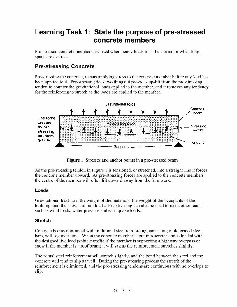
Pre-stressed concrete members are used when heavy loads must be carried or when long spans are desired. Pre-stressing Concrete Pre-stressing the concrete, means applying stress to the concrete member before any load has been applied to it. Pre-stressing does two things; it provides up-lift from the pre-stressing tendon to counter the gravitational loads applied to the member, and it removes any tendency for the reinforcing to stretch as the loads are applied to the member.
Figure 1 Stresses and anchor points in a pre-stressed beam As the pre-stressing tendon in Figure 1 is tensioned, or stretched, into a straight line it forces the concrete member upward. As pre-stressing forces are applied to the concrete members the centre of the member will often lift upward away from the formwork. Loads Gravitational loads are: the weight of the materials, the weight of the occupants of the building, and the snow and rain loads. Pre-stressing can also be used to resist other loads such as wind loads, water pressure and earthquake loads. Stretch Concrete beams reinforced with traditional steel reinforcing, consisting of deformed steel bars, will sag over time. When the concrete member is put into service and is loaded with the designed live load (vehicle traffic if the member is supporting a highway overpass or snow if the member is a roof beam) it will sag as the reinforcement stretches slightly. The actual steel reinforcement will stretch slightly, and the bond between the steel and the concrete will tend to slip as well. During the pre-stressing process the stretch of the reinforcement is eliminated, and the pre-stressing tendons are continuous with no overlaps to slip.
G-9 LEARNING TASK 1
G – 9 – 4
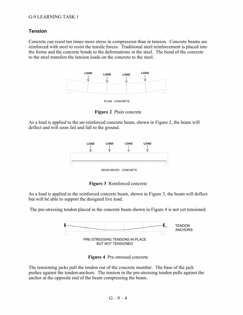
Tension Concrete can resist ten times more stress in compression than in tension. Concrete beams are reinforced with steel to resist the tensile forces. Traditional steel reinforcement is placed into the forms and the concrete bonds to the deformations in the steel. The bond of the concrete to the steel transfers the tension loads on the concrete to the steel.
Figure 2 Plain concrete As a load is applied to the un-reinforced concrete beam, shown in Figure 2, the beam will deflect and will soon fail and fall to the ground.
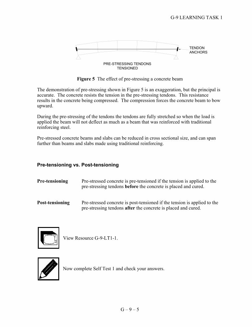
Figure 3 Reinforced concrete As a load is applied to the reinforced concrete beam, shown in Figure 3, the beam will deflect but will be able to support the designed live load. The pre-stressing tendon placed in the concrete beam shown in Figure 4 is not yet tensioned.
Figure 4 Pre-stressed concrete The tensioning jacks pull the tendon out of the concrete member. The base of the jack pushes against the tendon-anchors. The tension in the pre-stressing tendon pulls against the anchor at the opposite end of the beam compressing the beam.
TENDONANCHORS
PRE-STRESSING TENDONS IN PLACEBUT NOT TENSIONED
LOAD LOADLOADLOAD
PLAIN CONCRETE
LOAD LOAD LOAD LOAD
REINFORCED CONCRETE
G-9 LEARNING TASK 1
G – 9 – 5
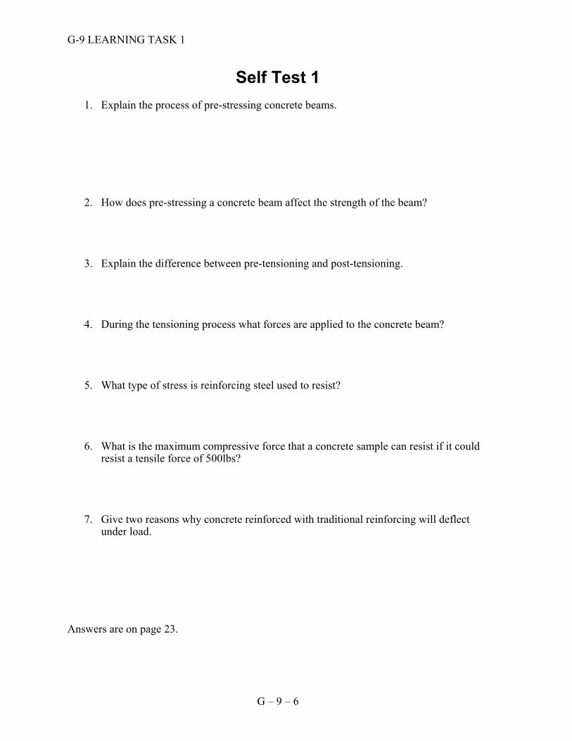
Figure 5 The effect of pre-stressing a concrete beam The demonstration of pre-stressing shown in Figure 5 is an exaggeration, but the principal is accurate. The concrete resists the tension in the pre-stressing tendons. This resistance results in the concrete being compressed. The compression forces the concrete beam to bow upward. During the pre-stressing of the tendons the tendons are fully stretched so when the load is applied the beam will not deflect as much as a beam that was reinforced with traditional reinforcing steel. Pre-stressed concrete beams and slabs can be reduced in cross sectional size, and can span further than beams and slabs made using traditional reinforcing. Pre-tensioning vs. Post-tensioning Pre-tensioning Pre-stressed concrete is pre-tensioned if the tension is applied to the
pre-stressing tendons before the concrete is placed and cured. Post-tensioning Pre-stressed concrete is post-tensioned if the tension is applied to the
pre-stressing tendons after the concrete is placed and cured.
View Resource G-9-LT1-1.
Now complete Self Test 1 and check your answers.
TENDONANCHORS
PRE-STRESSING TENDONS TENSIONED
G-9 LEARNING TASK 1
G – 9 – 6
Self Test 1
1. Explain the process of pre-stressing concrete beams.
2. How does pre-stressing a concrete beam affect the strength of the beam?
3. Explain the difference between pre-tensioning and post-tensioning.
4. During the tensioning process what forces are applied to the concrete beam?
5. What type of stress is reinforcing steel used to resist?
6. What is the maximum compressive force that a concrete sample can resist if it could resist a tensile force of 500lbs?
7. Give two reasons why concrete reinforced with traditional reinforcing will deflect under load.
Answers are on page 23.

G – 9 – 7
Learning Task 2: Describe methods of pre-tensioning pre-stressed concrete members
In pre-tensioned concrete members the tensioning of the pre-stressing tendons is done before the concrete is placed in the formwork. Once the concrete has cured to the design strength, the tendons are released from the abutments and the tensile force is transferred from the abutments to the concrete. Tensions in the pre-stressing tendons are great. The abutments that support the tensioning jacks must be solidly built to support the forces until the concrete has gained enough strength to carry the load (Figure 1).
Figure 1 Tie-downs for pre-tensioned concrete
The formwork for the pre-cast member is built between the tensioning abutments. The pre-stressing tendons are draped into the formwork. Hanging the tendons in a curve promotes the uplift of the concrete member when the tension is released onto the concrete. The shape of the curve of the pre-stressing tendons is carefully dimensioned on the shop drawings for each concrete beam. The pre-stressing tendons are held down during the tensioning process. The tie-down locations are also described in the shop drawings. Tensioning Process Hydraulic jacks are used to pull the pre-stressing tendons. The jacks pull the tendon against the concrete abutments on the casting bed. The tension in the tendon pulls against the opposite abutment, as show in Figure 2.
Figure 2 Tension from the tendon is supported by the abutments
DEAD END HYDRAULIC JACK
G-9 LEARNING TASK 2
G – 9 – 8
The tensioning abutments must be very strong to resist the stresses of the tensioning. The tensioning is done in small increments because the hydraulic jack can only pull the tendon a short distance. This requires a wedge-like device to hold the tendon against the abutment so that the tension is not released when the jack is let go. There could be hundreds of tendons to tension and they are tensioned in groups or individually. After the tensioning process is complete the concrete is placed into the forms. The concrete is steam cured until the design strength is reached then the tie-downs and tendons can be released. The tie-downs must be released first to allow the beam to be free to move when the tendons are released. Upon release of the tendons the concrete member will shrink in length slightly and the bottom will lift off of the casting bed.
Now complete Self Test 2 and check your answers.
K-8 LEARNING TASK 2
G – 9 – 9
Self Test 2
1. What is the purpose of the tie-downs?
2. Draw a sketch showing the forces acting on the tensioning abutments after the tension has been applied to the tendons.
3. How are the tendons held against the tension force while the concrete cures?
4. What is used to tension a pre-stressing tendon.
5. Where is the design information found for pre-tensioned concrete beams. Answers are on page 23.

G-9 LEARNING TASK 2
G – 9 – 10
Notes
G – 9 – 11
Learning Task 3: Describe methods of post-tensioning pre-stressed concrete members
In post-tensioning, tendons are tensioned after the concrete is cast and cured to the design strength. The tendons for post-tensioning differ from those for pre-tensioning. They are encased in a sleeve that allows the tendon to be pulled through the concrete. Safety The high stresses used in pre-stressing concrete create a significant hazard. During the stressing of the tendons there is the possibility of a “blowout”. Blowouts happen if the concrete is not strong enough to resist the stressing forces, or if the pre-stressing tendon was improperly positioned in the concrete. Pre-stressed concrete construction is designed by an engineer. The engineering drawings and stressing schedules must be followed very carefully. The following are a few precautions to be taken when working around pre-stressing operations.
• The tendons must be protected against damage during all phases of the construction process. A slight knick in a tendon can cause it to fail.
• Workers not involved with the tensioning must be kept clear of the danger area.
Signs and audible signals should be used to warn workers of the danger areas.
• During pre-stressing, guards made from ¼” thick plate steel must be positioned to protect workers from flying materials if the tendon was to break.
• All blowouts that occur must be reported to the structural design engineer and
investigated. A log of all blowouts must be kept for future reference.
• Handle pre-stressing tendons carefully their strength capability makes them stiff and likely to spring loose and injure those handling them.
Renovations Drilling a hole in a pre-stressed slab, beam, or girder is not a simple operation. If a pre-stressing tendon is damaged it may break releasing over 100,000 lbs of stress. This release of stress is like a bomb exploding and the broken pieces will fly apart.
Before drilling, cutting, or fastening to a concrete slab determine if it is a pre-stressed slab. If a pre-stressed slab needs to be worked on obtain written procedures from a registered professional engineer before continuing.
G-9 LEARNING TASK 3
G – 9 – 12
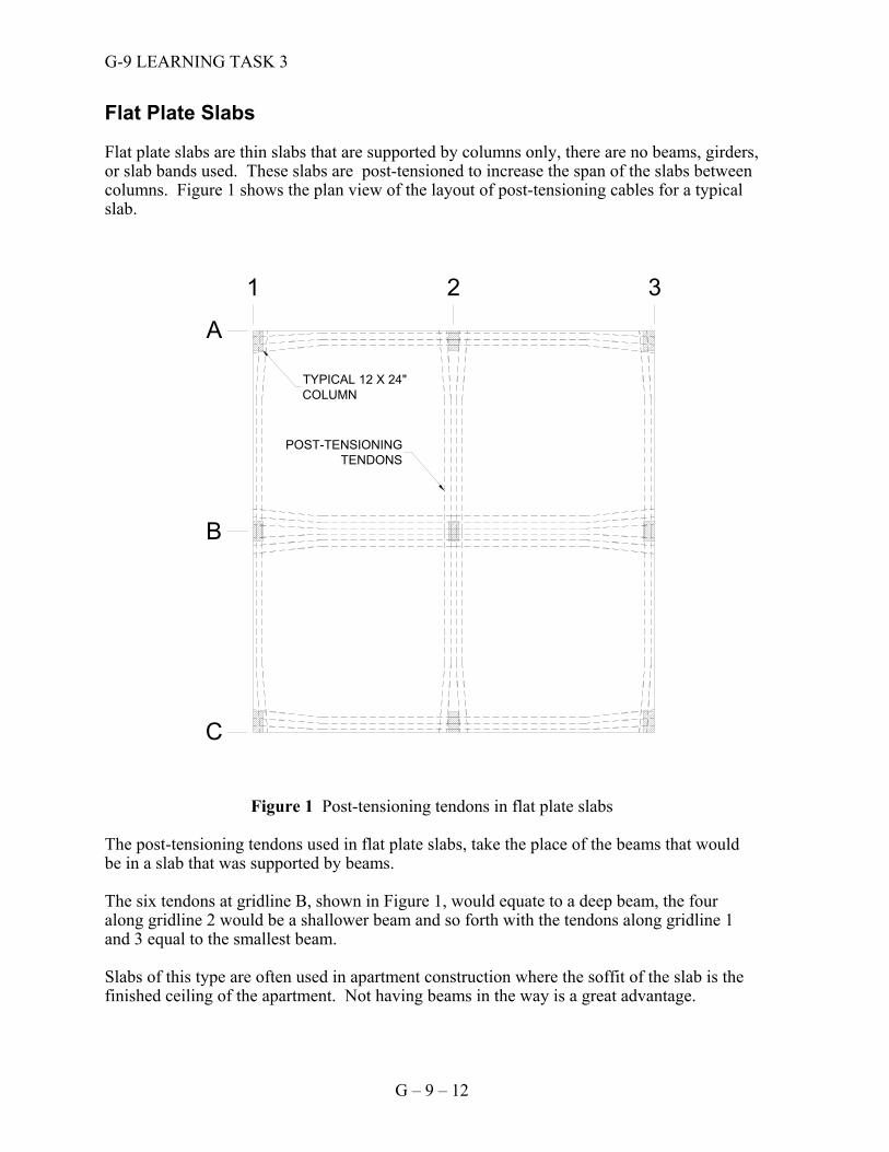
Flat Plate Slabs Flat plate slabs are thin slabs that are supported by columns only, there are no beams, girders, or slab bands used. These slabs are post-tensioned to increase the span of the slabs between columns. Figure 1 shows the plan view of the layout of post-tensioning cables for a typical slab.
Figure 1 Post-tensioning tendons in flat plate slabs The post-tensioning tendons used in flat plate slabs, take the place of the beams that would be in a slab that was supported by beams. The six tendons at gridline B, shown in Figure 1, would equate to a deep beam, the four along gridline 2 would be a shallower beam and so forth with the tendons along gridline 1 and 3 equal to the smallest beam. Slabs of this type are often used in apartment construction where the soffit of the slab is the finished ceiling of the apartment. Not having beams in the way is a great advantage.
TYPICAL 12 X 24"COLUMN
POST-TENSIONINGTENDONS
A
B
C
1 2 3
G-9 LEARNING TASK 3
G – 9 – 13
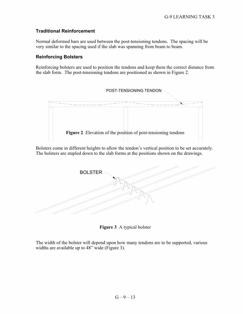
Traditional Reinforcement Normal deformed bars are used between the post-tensioning tendons. The spacing will be very similar to the spacing used if the slab was spanning from beam to beam. Reinforcing Bolsters Reinforcing bolsters are used to position the tendons and keep them the correct distance from the slab form. The post-tensioning tendons are positioned as shown in Figure 2.
Figure 2 Elevation of the position of post-tensioning tendons
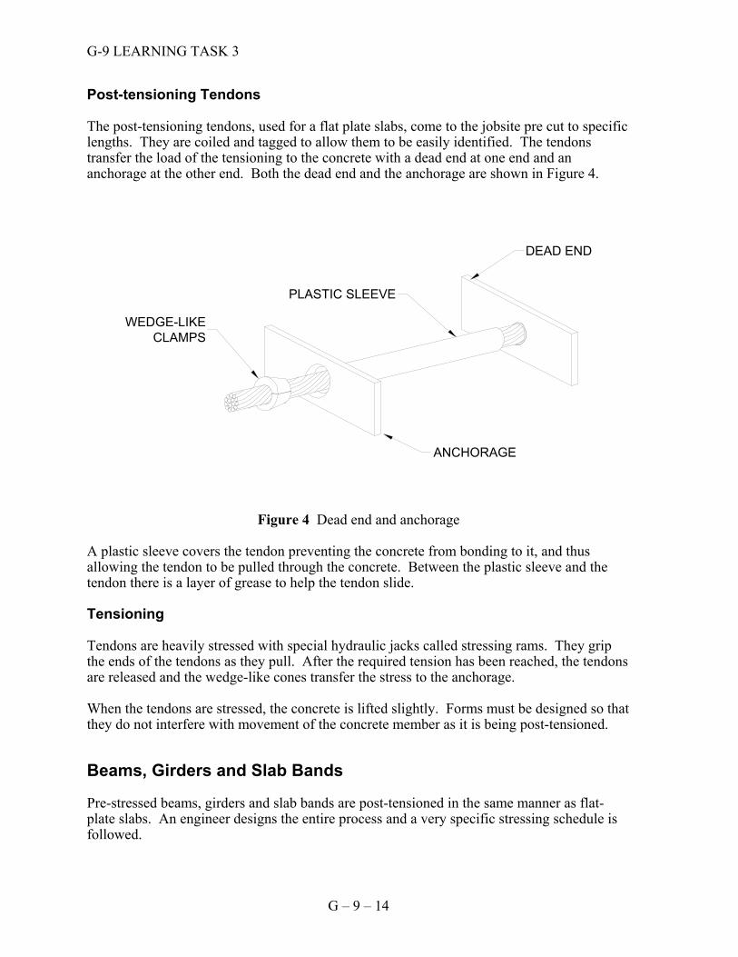
Bolsters come in different heights to allow the tendon’s vertical position to be set accurately. The bolsters are stapled down to the slab forms at the positions shown on the drawings.
Figure 3 A typical bolster The width of the bolster will depend upon how many tendons are to be supported, various widths are available up to 48” wide (Figure 3).
POST-TENSIONING TENDON
BOLSTER
G-9 LEARNING TASK 3
G – 9 – 14
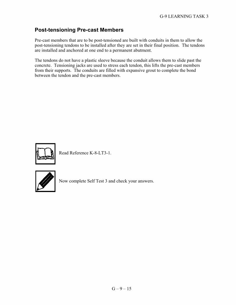
Post-tensioning Tendons The post-tensioning tendons, used for a flat plate slabs, come to the jobsite pre cut to specific lengths. They are coiled and tagged to allow them to be easily identified. The tendons transfer the load of the tensioning to the concrete with a dead end at one end and an anchorage at the other end. Both the dead end and the anchorage are shown in Figure 4.
Figure 4 Dead end and anchorage A plastic sleeve covers the tendon preventing the concrete from bonding to it, and thus allowing the tendon to be pulled through the concrete. Between the plastic sleeve and the tendon there is a layer of grease to help the tendon slide. Tensioning Tendons are heavily stressed with special hydraulic jacks called stressing rams. They grip the ends of the tendons as they pull. After the required tension has been reached, the tendons are released and the wedge-like cones transfer the stress to the anchorage. When the tendons are stressed, the concrete is lifted slightly. Forms must be designed so that they do not interfere with movement of the concrete member as it is being post-tensioned. Beams, Girders and Slab Bands Pre-stressed beams, girders and slab bands are post-tensioned in the same manner as flat-plate slabs. An engineer designs the entire process and a very specific stressing schedule is followed.
DEAD END
PLASTIC SLEEVE
WEDGE-LIKE CLAMPS
ANCHORAGE
G-9 LEARNING TASK 3
G – 9 – 15
Post-tensioning Pre-cast Members Pre-cast members that are to be post-tensioned are built with conduits in them to allow the post-tensioning tendons to be installed after they are set in their final position. The tendons are installed and anchored at one end to a permanent abutment. The tendons do not have a plastic sleeve because the conduit allows them to slide past the concrete. Tensioning jacks are used to stress each tendon, this lifts the pre-cast members from their supports. The conduits are filled with expansive grout to complete the bond between the tendon and the pre-cast members.
Read Reference K-8-LT3-1.
Now complete Self Test 3 and check your answers.
G-9 LEARNING TASK 3
G – 9 – 16
Self Test 3
1. Who is responsible for the design of the pre-stressing procedures?
2. What is the purpose of the plastic sleeve on a pre-stressing tendon?
3. What is the purpose of the grout when post-tensioning pre-cast members?
4. List five safety precautions used when working around a pre-stressing operation.
5. What is used to hold the stressed tendon in place?
6. Explain how post-tensioning supports a flat plate slab. Answers are on page 23.
G – 9 – 17
Learning Task 4: Describe pre-cast construction techniques
Construction with pre-cast members requires careful planning so that components are installed correctly and without damage. Building with pre-cast concrete units is like stacking blocks of wood, one unit rests upon the other. Like a pile of wooden blocks, the concrete units will fall down if not properly connected and braced. Moving and Placing Moving pre-cast members, which may be quite delicate, requires careful rigging and lifting by ground workers and crane operators. Cradles, strong-backs, and nylon slings are often used. The slings are connected to inserts or lifting loops cast into the units. The lifting ring or loop is cut off once the pre-cast components are set in place. Permanent fastening of components is made by bolts, grout or welding. Temporary Bracing The temporary bracing of pre-cast components must be completely installed before the crane releases the tension from the hoisting lines. All temporary bracing should be inspected prior to leaving the job each day to ensure that it is still securely attached and supporting the members adequately. Temporary bracing must be designed to withstand the wind pressures from winds in excess of 100kmh. Order of Assembly One advantage of pre-cast buildings is that they can be erected very quickly. The engineer prepares detailed erection drawings, which described the erection procedures. The engineer must approve any changes to the erection procedure prior to implementing the changes. The assembly sequence for structures with pre-cast units varies with the size and availability of lifting equipment. Once the materials are ready, the crane should be continuously on site throughout assembly of the building. Columns are sometimes placed before rough floor slabs are cast, but usually footings and floor slabs are in place before columns are erected. Girders that are supported by the columns are installed next. Smaller beams that intersect with the girders are installed against them. All of theses elements are connected and braced while the crane holds them in place. The temporary connections may be made with bolts or welds and the bracing is usually done with guy wires.
G-9 LEARNING TASK 4
G – 9 – 18
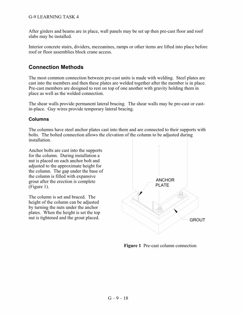
After girders and beams are in place, wall panels may be set up then pre-cast floor and roof slabs may be installed. Interior concrete stairs, dividers, mezzanines, ramps or other items are lifted into place before roof or floor assemblies block crane access. Connection Methods The most common connection between pre-cast units is made with welding. Steel plates are cast into the members and then these plates are welded together after the member is in place. Pre-cast members are designed to rest on top of one another with gravity holding them in place as well as the welded connection. The shear walls provide permanent lateral bracing. The shear walls may be pre-cast or cast-in-place. Guy wires provide temporary lateral bracing. Columns The columns have steel anchor plates cast into them and are connected to their supports with bolts. The bolted connection allows the elevation of the column to be adjusted during installation. Anchor bolts are cast into the supports for the column. During installation a nut is placed on each anchor bolt and adjusted to the approximate height for the column. The gap under the base of the column is filled with expansive grout after the erection is complete (Figure 1). The column is set and braced. The height of the column can be adjusted by turning the nuts under the anchor plates. When the height is set the top nut is tightened and the grout placed.
GROUT
ANCHORPLATE
Figure 1 Pre-cast column connection
G-9 LEARNING TASK 4
G – 9 – 19
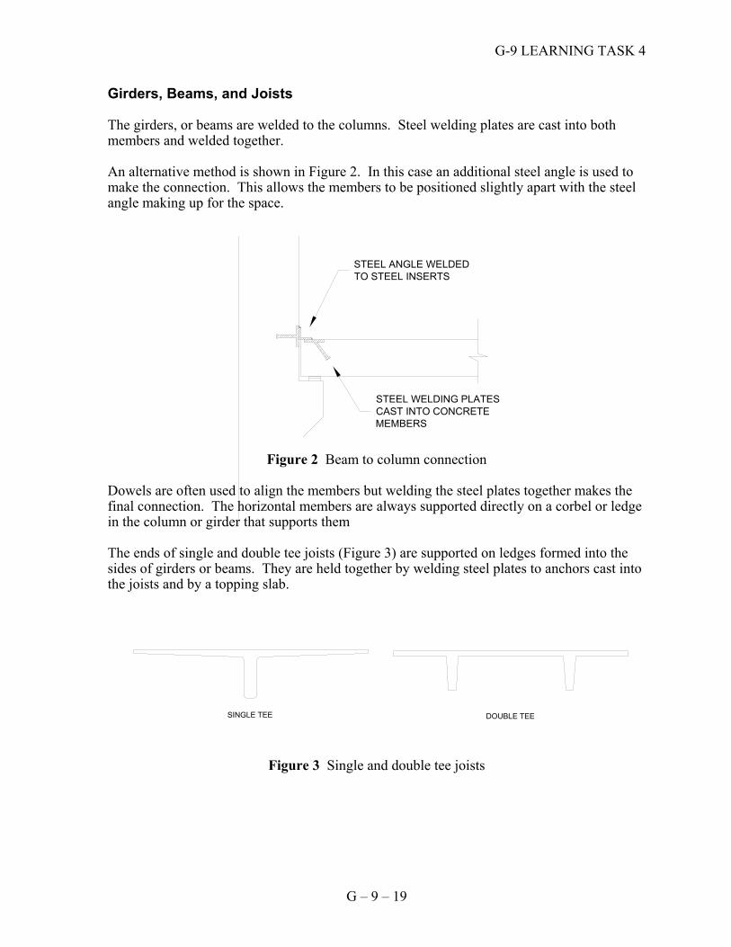
Girders, Beams, and Joists The girders, or beams are welded to the columns. Steel welding plates are cast into both members and welded together. An alternative method is shown in Figure 2. In this case an additional steel angle is used to make the connection. This allows the members to be positioned slightly apart with the steel angle making up for the space.
Figure 2 Beam to column connection
Dowels are often used to align the members but welding the steel plates together makes the final connection. The horizontal members are always supported directly on a corbel or ledge in the column or girder that supports them The ends of single and double tee joists (Figure 3) are supported on ledges formed into the sides of girders or beams. They are held together by welding steel plates to anchors cast into the joists and by a topping slab.
Figure 3 Single and double tee joists
STEEL WELDING PLATESCAST INTO CONCRETE MEMBERS
STEEL ANGLE WELDED TO STEEL INSERTS
SINGLE TEE DOUBLE TEE
G-9 LEARNING TASK 4
G – 9 – 20
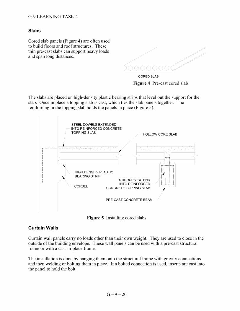
Slabs Cored slab panels (Figure 4) are often used to build floors and roof structures. These thin pre-cast slabs can support heavy loads and span long distances. The slabs are placed on high-density plastic bearing strips that level out the support for the slab. Once in place a topping slab is cast, which ties the slab panels together. The reinforcing in the topping slab holds the panels in place (Figure 5).
Figure 5 Installing cored slabs
Curtain Walls Curtain wall panels carry no loads other than their own weight. They are used to close in the outside of the building envelope. These wall panels can be used with a pre-cast structural frame or with a cast-in-place frame. The installation is done by hanging them onto the structural frame with gravity connections and then welding or bolting them in place. If a bolted connection is used, inserts are cast into the panel to hold the bolt.
HIGH DENSITY PLASTICBEARING STRIP
STEEL DOWELS EXTENDEDINTO REINFORCED CONCRETETOPPING SLAB
STIRRUPS EXTENDINTO REINFORCED
CONCRETE TOPPING SLAB
PRE-CAST CONCRETE BEAM
HOLLOW CORE SLAB
CORBEL
CORED SLAB
Figure 4 Pre-cast cored slab
G-9 LEARNING TASK 4
G – 9 – 21
Finishing Between Pre-cast Units Grouting usually finishes the connection between structural members. The grout provides a continuous bearing surface for vertical connections and stiffens horizontal connections. Installing backer rod and caulking finishes exterior pre-cast units. The backer rod is inserted before the caulking, to support the caulking and assist in sealing the joint. Roof and Floor Concreting Single or double tee joists, or cored slabs form the structural components of the roof or floor slab. A topping slab is added to provide roofs and floors with a level and smooth finished surface. The topping slab is between 30 mm and 150 mm thick, and usually contains wire mesh reinforcement. For roof slabs the slab may be made with low density insulating concrete.
Read Reference G-9-LT4-1.
Now complete Self Test 4 and check your answers.
G-9 LEARNING TASK 4
G – 9 – 22
Self Test 4
1. How are cored slabs connected to the beams that support them?
2. What type of grout is used under pre-cast columns?
3. How are steel angles used to connect pre-cast members?
4. How are topping slabs reinforced?
5. How are pre-cast columns set on their bases?
6. Describe the order of assembly of pre-cast building components.
7. What is a “curtain wall”? Answers are on page 23.
G – 9 – 23
Answer Sheet The answers to all of the questions in the Self Tests in this competency are obtained from the learning guide and reference material. This answer key givesdirections to where in the learning guide the relevant material can be found. For further explanations see your instructor. The written exam for this competency will be based upon the material in the learning guide and the references. Self Test 1 - page 6
1. page 3 2. page 3 3. page 5 4. pages 3 &4 5. page 4 6. page 4 7. page 4
Self Test 2 - page 9
1. page 7 2. page 7 3. page 8 4. page 7 5. page 7
Self Test 3 - page 16
1. page 11 2. page 14 3. page 15 4. page 11 5. page 14 6. page 12
Self Test 4 - page 22
1. page 20 2. page 18 3. page 19 4. page 21 5. page 18 6. page 17 7. page 20

G – 9 – 24
Notes