Embed Size (px)
Citation preview

International Journal of Bridge Engineering (IJBE), Vol. 5, No. 2, (2017), pp. 81-102
COMPARISON BETWEEN THE BEHAVIOUR OF THE
DIFFERENT SHAPES OF PYLON IN THE LINEAR
STATIC ANALYSIS OF CABLE STAYED BRIDGE
USING SAP2000
Hussain Hararwala1, Savita Maru
2
1,2 Department of Civil Engineering, Govt. Engineering College, Ujjain - 456001, India e-mail: [email protected], [email protected]
ABSTRACT: This paper deals with the linear static analysis of Cable Stayed
Bridges with different shapes of pylons under its own weight. The cable stayed
bridge is one of the modern bridges which were built for the longer spans.
Therefore, there is a need of study on the behaviour of the pylons before implementing it in actual practice. For this study, the different shapes of Pylons
have been compared with the bridge span dimension and other parameters are
kept unvarying. The different shapes of Pylons considered for Cable Stayed Bridge are A type, H type, inverted Y type, Single pylon, Diamond shaped,
Pyramid Shaped, U-Shaped & Hexagonal Shaped. The height of the pylon
remains same for all the models of Cable Stayed Bridge with different shapes of Pylons. The modelling of bridge has been prepared using SAP 2000 software.
For this study, the arrangement of cable stay has been taken as semi fan type as
well as fan type. The study reveals the following points regarding to the
behaviour of Pylons such as the Axial Force in Pylon, Bending Moment in Pylon, and Shear Force in Pylon & Deflection at the top of Pylon. This study
will be helpful for make an appropriate choice for the shape of Pylon used for
Cable Stayed Bridge in particular conditions.
KEYWORDS: Cable Stayed Bridge, Pylons, Semi Fan & Fan Type
Arrangement of Cable Stays, Dead Load, Linear Static Analysis, SAP 2000.
1 INTRODUCTION
1.1 General Many constructions of cable stayed bridges have been auspiciously completed around over the world from last two decades of the 20th century. Due to their
highly substantial display & incomparably appropriated structural materials,
cable stayed bridges have been taken as one of the most popular type of bridges
in last decades. With the increase in the length of span of bridges, the modern cable stayed bridges are more sufficient & extensible strong enough to the wind
forces as compare to ever. A typical cable stayed bridge consists of deck with

82 Comparison between the behaviour of the different shapes of pylon
one or two pylons uplifted by the piers or the walls in the middle of the span.
The cables are connected at some angle to the girder to provide additional
supports. The vertical loads on the deck are carried by the cable stays which are in tension. The tensile forces in the stay cables influence horizontal
compression in the deck. The Pylon transfers the forces developed in the cables
to the foundation through vertical compression. The design of the bridge is figure out such that the static horizontal forces resulting from dead load are
almost balanced to minimize the height of the pylon. Cable stayed-bridges have
a low centre of gravity, which makes them capable in opposing the effects of
earthquakes. Cable stayed bridges provide outstanding architectural display due to their small diameter of cables and exclusive upper part of structure. It can be
constructed by cantilevering action from the tower i.e. the cables act both as
temporary and permanent supports to the bridge deck. The advantage of cable-stayed bridges is that it can be built with any number of towers.
Figure 1. An illustration of typical cable stayed bridge
In last few years, several cable-stayed bridges have been constructed with different shapes of pylons such as H-shaped, A-shaped, Diamond shaped,
Inverted Y-shaped etc. as shown in figure below which results in a great interest
to determine the behaviour of different shapes of pylon used for cable stayed
bridges. Therefore, the behaviour of the bridge can be computed by performing the analysis using finite element programmes.
Figure 2. Different tower/pylons available for cable stayed bridge
Hararwala & Maru 83
The purpose of the pylon in the Cable Stayed Bridge is to support the cable
system and transfer forces to the foundations. They are loaded with high
compressions and bending moments that depend on the stay cable formation and the deck-pylon support conditions. Pylons can be made of steel or concrete,
being the latter generally more economic considering similar stiffness
conditions. Thus, the behaviour of the pylons will be conditioned by several aspects, and in addition to the previous idea, the geometric shape of the pylons
which depends on the applied loads, cable-stay system and aesthetic conditions,
is a very important aspect. The behaviour of the different shapes of the Pylon
was studied by the computational analysis using software SAP 2000. SAP is finite element based program and is recognized by international community for
the research purpose. SAP program will generate the various results like joint
displacements, joint forces, joint reactions, base reactions, deck force, forces in cables and pylons, moments in deck & pylons, mode shapes etc.
1.2 Components of cable stayed bridge Different components of cable supported bridge like deck, pylon, and cable-
stays are discussed below:
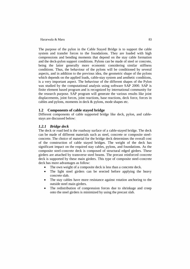
1.2.1 Bridge deck The deck or road bed is the roadway surface of a cable-stayed bridge. The deck
can be made of different materials such as steel, concrete or composite steel-concrete. The choice of material for the bridge deck determines the overall cost
of the construction of cable stayed bridges. The weight of the deck has
significant impact on the required stay cables, pylons, and foundations. As the
composite steel-concrete deck is composed of structural edged girders. These girders are attached by transverse steel beams. The precast reinforced concrete
deck is supported by these main girders. This type of composite steel-concrete
deck has more advantages as follow:
The own weight of a composite deck is less than a concrete deck.
The light steel girders can be erected before applying the heavy
concrete slab.
The stay cables have more resistance against rotation anchoring to the
outside steel main girders.
The redistribution of compression forces due to shrinkage and creep
onto the steel girders is minimized by using the precast slab.
84 Comparison between the behaviour of the different shapes of pylon
Figure 3. Typical Section of Concrete Deck
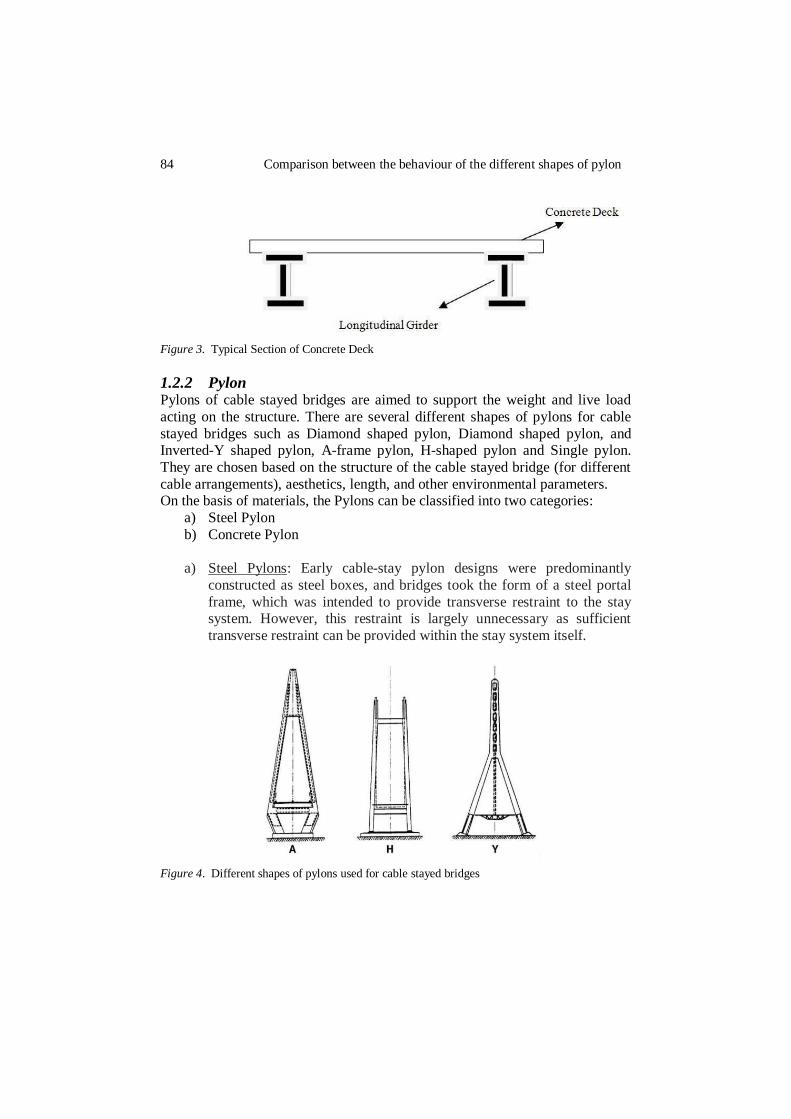
1.2.2 Pylon Pylons of cable stayed bridges are aimed to support the weight and live load
acting on the structure. There are several different shapes of pylons for cable
stayed bridges such as Diamond shaped pylon, Diamond shaped pylon, and Inverted-Y shaped pylon, A-frame pylon, H-shaped pylon and Single pylon.
They are chosen based on the structure of the cable stayed bridge (for different
cable arrangements), aesthetics, length, and other environmental parameters. On the basis of materials, the Pylons can be classified into two categories:
a) Steel Pylon
b) Concrete Pylon
a) Steel Pylons: Early cable-stay pylon designs were predominantly
constructed as steel boxes, and bridges took the form of a steel portal
frame, which was intended to provide transverse restraint to the stay system. However, this restraint is largely unnecessary as sufficient
transverse restraint can be provided within the stay system itself.
Figure 4. Different shapes of pylons used for cable stayed bridges
Hararwala & Maru 85
b) Concrete Pylons: Concrete is very efficient when supporting loads in
axial compression. Advances in concrete construction and modern
formwork technology have made the use of concrete increasingly competitive for pylon construction, despite the much greater self-weight
when compared with a steel alternative. Concrete has proved
particularly adaptable to the more complex forms of pylon.
1.2.3 Cables Cables are one of the main parts of a cable-stayed bridge. They transfer the dead weight of the deck to the pylons. These cables are usually post-tensioned based
on the weight of the deck. The cables post-tensioned forces are selected in a
way to minimize both the vertical deflection of the deck and lateral deflection of the pylons. There are four major types of stay cables including, parallel-bar,
parallel-wire, standard, and locked-coil cables. The choice of these cables
depends mainly on the mechanical properties, structural properties and
economical criteria. Different types of cable-stayed bridges are discussed based on the
arrangement of stay cables including fan, and semi-fan as depicted.
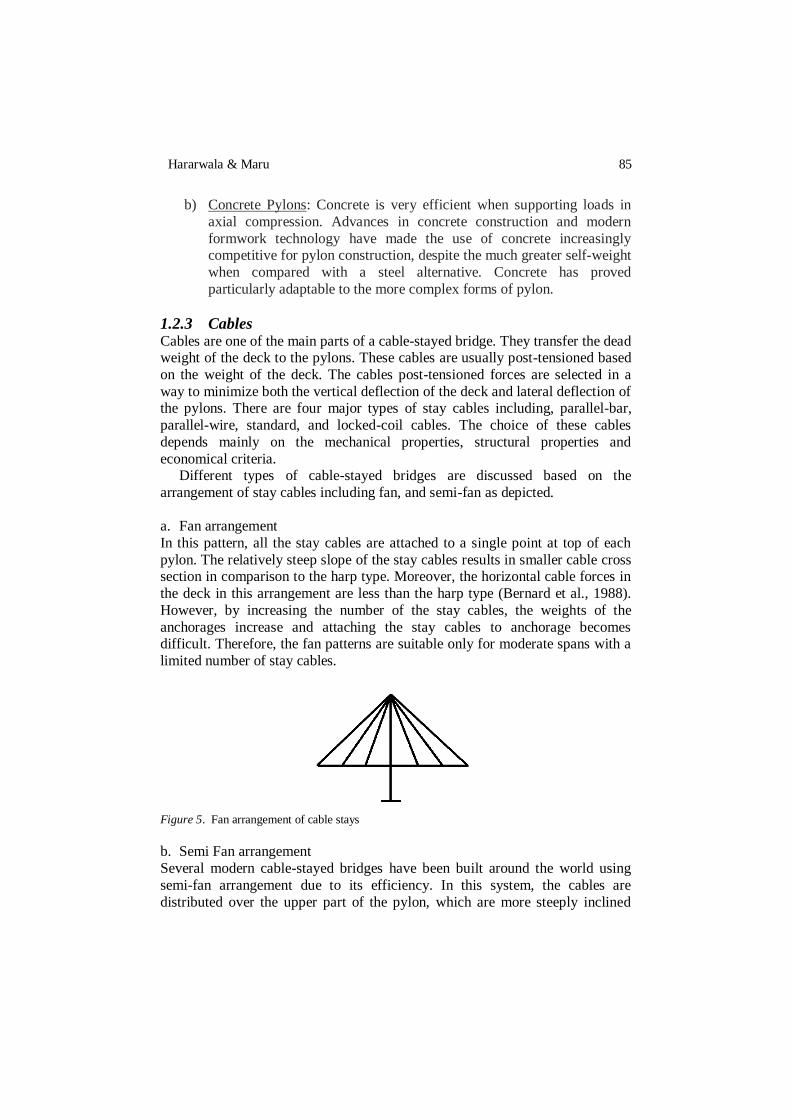
a. Fan arrangement
In this pattern, all the stay cables are attached to a single point at top of each
pylon. The relatively steep slope of the stay cables results in smaller cable cross section in comparison to the harp type. Moreover, the horizontal cable forces in
the deck in this arrangement are less than the harp type (Bernard et al., 1988).
However, by increasing the number of the stay cables, the weights of the
anchorages increase and attaching the stay cables to anchorage becomes difficult. Therefore, the fan patterns are suitable only for moderate spans with a
limited number of stay cables.
Figure 5. Fan arrangement of cable stays
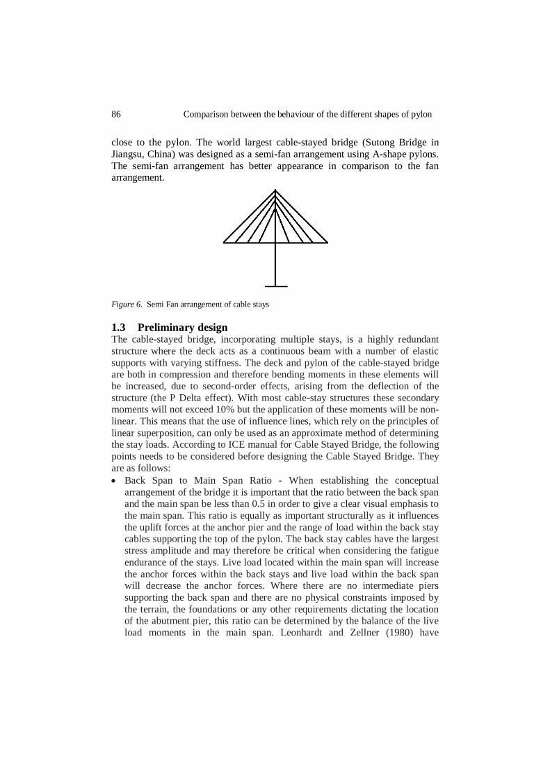
b. Semi Fan arrangement
Several modern cable-stayed bridges have been built around the world using
semi-fan arrangement due to its efficiency. In this system, the cables are
distributed over the upper part of the pylon, which are more steeply inclined
86 Comparison between the behaviour of the different shapes of pylon
close to the pylon. The world largest cable-stayed bridge (Sutong Bridge in
Jiangsu, China) was designed as a semi-fan arrangement using A-shape pylons.
The semi-fan arrangement has better appearance in comparison to the fan arrangement.
Figure 6. Semi Fan arrangement of cable stays
1.3 Preliminary design The cable-stayed bridge, incorporating multiple stays, is a highly redundant
structure where the deck acts as a continuous beam with a number of elastic
supports with varying stiffness. The deck and pylon of the cable-stayed bridge are both in compression and therefore bending moments in these elements will
be increased, due to second-order effects, arising from the deflection of the
structure (the P Delta effect). With most cable-stay structures these secondary moments will not exceed 10% but the application of these moments will be non-
linear. This means that the use of influence lines, which rely on the principles of
linear superposition, can only be used as an approximate method of determining the stay loads. According to ICE manual for Cable Stayed Bridge, the following
points needs to be considered before designing the Cable Stayed Bridge. They
are as follows:
Back Span to Main Span Ratio - When establishing the conceptual
arrangement of the bridge it is important that the ratio between the back span and the main span be less than 0.5 in order to give a clear visual emphasis to
the main span. This ratio is equally as important structurally as it influences
the uplift forces at the anchor pier and the range of load within the back stay cables supporting the top of the pylon. The back stay cables have the largest
stress amplitude and may therefore be critical when considering the fatigue
endurance of the stays. Live load located within the main span will increase
the anchor forces within the back stays and live load within the back span will decrease the anchor forces. Where there are no intermediate piers
supporting the back span and there are no physical constraints imposed by
the terrain, the foundations or any other requirements dictating the location of the abutment pier, this ratio can be determined by the balance of the live
load moments in the main span. Leonhardt and Zellner (1980) have
Hararwala & Maru 87
determined the back span to main span ratio with respect to these
parameters. For a highway structure where the live loading is typically 0.25
of the dead load the theoretical ratio is 0.38. However, this calculation ignores the bending stiffness of the deck. When this stiffness is taken into
consideration the optimum length of the back span is more likely to be
between 0.4 and 0.45 of the main span.
Stay Spacing - The spacing of the stay anchors along the deck should be
compatible with the capacity of the longitudinal girders and limit the stay
size so that the breaking load is less than 25-30 MN. The capacity of the
longitudinal girders is likely to be critical when considering the case of an
accidental severance of a stay (stay out condition). The spacing should also be small enough so that the deck may be erected by the free cantilevering
method without the need for auxiliary stays or supports. These requirements
will effectively limit the spacing within the range 5–15 m. The heavier concrete construction will require the smaller stay spacing while the larger
stay spacing is more suitable for steel or steel composite construction.
Deck Stiffness - The deflection of the longitudinal girders is primarily
determined by the stay layout. It is reasonable therefore that the depth of the longitudinal girders should be kept to a minimum, subject to sufficient area
and stiffness being provided to carry the large compressive forces without
buckling. When checking the longitudinal girders for the stay out condition
the PTI Recommendations (2001) stipulate that the structure should provide for the replacement of any individual stay with a controlled reduction of the
live load during any stay exchange. The structure must also be capable of
withstanding the accidental loss of any individual stay without structural instability occurring.
Pylon Height - The height of the pylon will determine the overall stiffness of
the structure. As the stay angle (α) increases, the required stay size will
decrease and the height of the pylon will increase. However, the deflection of the deck will increase as each stay becomes longer. Both the weight of the
stay and the deflection of the deck become a minimum when the expression
1/(sinα x cosα) is also a minimum. Therefore the most efficient stay is that
with a stay inclination of 45 degree. In practice the efficiency of the stay is not significantly impaired when the stay inclination is varied within
reasonable limits, which may be taken as 25–65 degrees. The stay inclined at
25 degrees will be the outer stay connecting the anchor pier and the deck panel adjacent to the centre of the main span to the top of the pylon. The stay
inclined at 65 degrees will be that located nearest the pylon. This implies an
optimum ratio of pylon height above the deck (H) to main span (L) is
between 0.2 and 0.25.
Deck Form - The selection of the deck form will usually be based on an
economic evaluation of the possible alternatives. The primary factors

88 Comparison between the behaviour of the different shapes of pylon
influencing the choice of deck will be the length of the main span and deck
width. Other factors such as the cost of foundations, the local availability of
materials or labour skills and the competitive conditions at the time of tendering may also have influence over the costs. A study by Svensson
(1995) has undertaken an economic comparison of the various types of deck
sections within the span range 200–1000 m. The study concluded that a concrete deck section is the most economic deck section within the span
range 200–400m and the composite deck above 400 m. However, the
difference in cost is marginal close to the division between the two deck
forms, and local factors are often decisive in the final choice. The study also does not consider the influence of any variation in the width of deck. The use
of concrete construction in wide decks where there are six or more traffic
lanes requires substantial crossbeams and the additional weight of these will penalise those spans near the upper end of the economic range.
Non-linear material properties will also influence the design. Apart from the
behaviour of the stays under load, all concrete and concrete and steel composite decks will be subject to the effects of creep and shrinkage during both
construction and the service life of the completed structure. It can therefore be
seen that a preliminary design by manual calculation should be considered as
the first stage in an interactive design process, providing a basis for a more rigorous analysis.
2 STUDY UNDERTAKEN It was always key point of research for choice of strength and durability of the structure and economical structural system. The pylons or towers play an
important role in the strength and durability of cable stayed bridge. Hence it is
very necessary to determine the study of behaviour of different shapes of pylon
before implementing it in actual practice which gives an idea for the adequate strength of cable stayed bridge in a particular condition. On the other hand, for
economical system, different types of materials can be used for pylons either it
can be of concrete or of steel. For designers or structural engineers, these particular studies are very essential for predetermination of behaviour of cable
stayed bridge under different conditions.
The specific objective of this study is that it gives an initial idea to the designer or structural engineer that which shape of pylon should be taken into
account for the adequate strength and durability of cable stayed bridge having
main span of 350 m. For better enhancement, the following points are taken into
consideration: a. The arrangement of cable stays i.e. semi fan arrangement as well as fan
arrangement.
b. The different cross sections of pylons i.e. rectangular & circular.

Hararwala & Maru 89
This thesis will provide the comparison between the different shapes of pylons
of different materials. Thus from the results obtained, one can easily identify the
most suitable shape of pylon and the material used for pylon for better strength and durability and for economical structural system.
The modelling & analysis of the Cable Stayed Bridge will have been carried
out by the software SAP 2000. In the analysis of the bridge the most important part is modelling. Different components of bridges like deck, pylon, cables etc
must be modelled as per the actual forces they are subjected. The dimension of
bridge which was taken in consideration here was situated at river Ravi in
Jammu Kashmir, India. The various shapes of pylon have been considered for the analysis are Diamond shaped, A-shaped, H-shaped, Inverted Y-shaped,
single pylon shaped, Pyramid Shaped, U-Shaped & H-Shaped. There are
different types of cable-stayed bridges which are distinguished on the basis of the arrangement of stay cables; they are called as harp arrangement, fan
arrangement, and semi-fan arrangement. In this analysis, the considerations of
the fan & semi fan arrangement of cables have been taken, & the analyses will be computed for concrete pylons as well as for steel pylons. The pylons which
have been modelled for analysis purpose having their section rectangular as
well as circular. Different elements of cable supported bridge like deck, pylon,
and cable-stays are discussed below: a) Bridge deck: Deck is modelled as an area section with varying depths at
side span and main span for balancing the member.
b) Pylon: Pylon and pylon beam is modelled as a frame section where the pylon with the vertical orientation and pylon beam with horizontal
orientation.
c) Cables: Cables of the cable stayed bridge are modelled as cable element. The
cable elements act as axial load transfer element only. For particular this analysis, the spacing between cables which are attached at pylons kept as 2
m. for semi fan type pylons used in each Cable Stayed Bridge. The cable is
modelled as a straight guyed structure.
The modelling of cable stayed bridge in SAP is prepared as per following
procedure:
MODELLING PROCEDURE ON SAP
a) Draw the geometry of the bridge either by inserting coordinates.
b) Define the materials and sections for the members
c) Define the loading values to be applied on the structures. d) Now assign the defined section as the members.
e) After assigning everything, set the analysis to be carried out and press
run analysis.
SAP program will generate the various results like joint displacements, joint
90 Comparison between the behaviour of the different shapes of pylon
forces, joint reactions, base reactions, deck force, axial forces in cables and
pylons, bending moment in pylon, shear force in pylon, mode shapes etc.
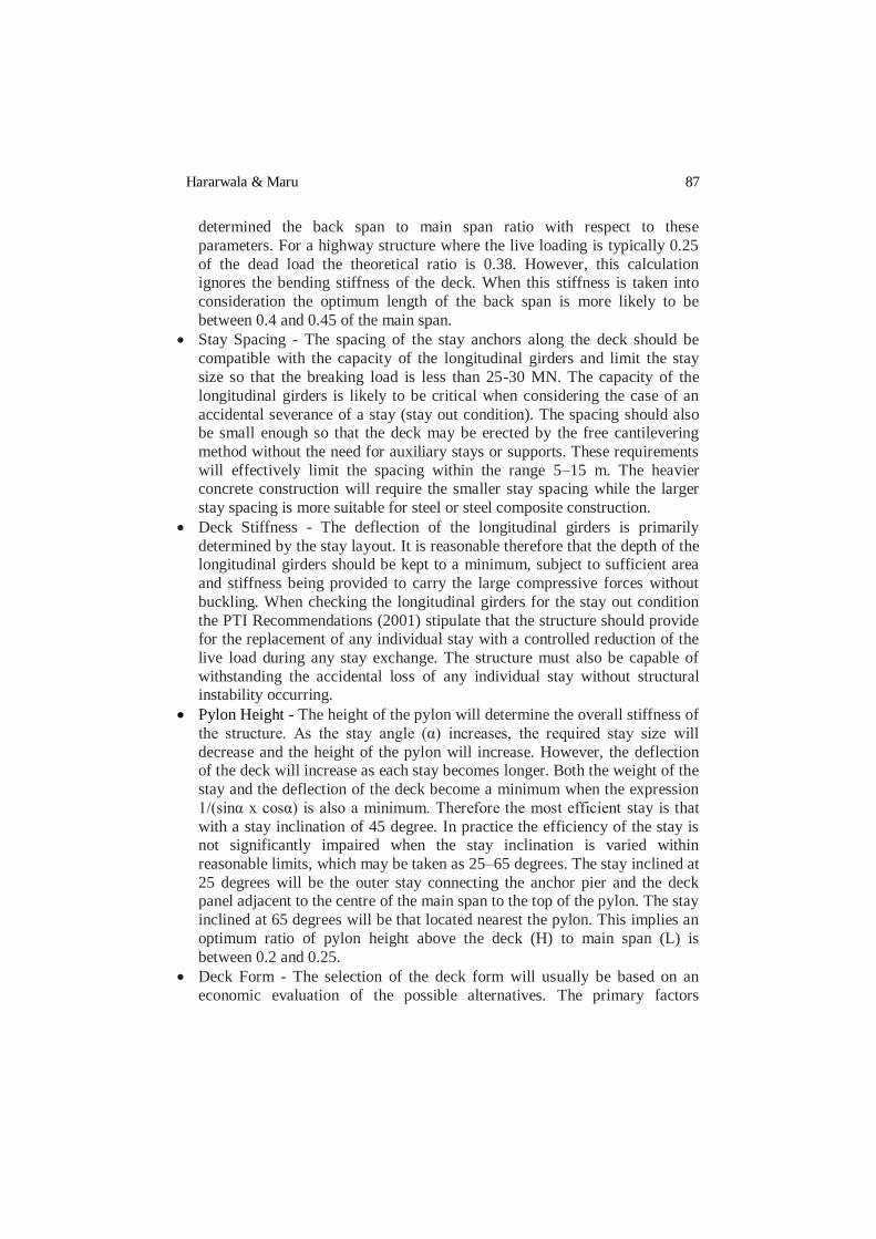
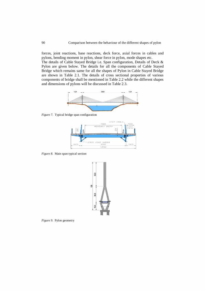
The details of Cable Stayed Bridge i.e. Span configuration, Details of Deck & Pylon are given below. The details for all the components of Cable Stayed
Bridge which remains same for all the shapes of Pylon in Cable Stayed Bridge
are shown in Table 2.1. The details of cross sectional properties of various components of bridge shall be mentioned in Table 2.2 while the different shapes
and dimensions of pylons will be discussed in Table 2.3.
Figure 7. Typical bridge span configuration
Figure 8. Main span typical section
Figure 9. Pylon geometry

Hararwala & Maru 91
Table 2.1 Details of the components of cable stayed bridge
S. No. Component Material Shape Dimension
(in m.)
1. Cable Steel Circular 0.40
2.
Deck at Side
Span Concrete Rectangular
Depth- 0.300
Length- 121
Deck at Main Span
Concrete Rectangular Depth- 0.225
Length- 350
3. Side Span End Cross Beams
Steel I-Section
1 x 0.5
Tf= 0.15
Tw= 0.15
4. Main Span End
Cross Beams Steel I-Section
0.9 x 0.5
Tf= 0.15
Tw= 0.15
5. Side Span
Girders Steel I-Section
0.7 x 0.3
Tf= 0.1
Tw= 0.1
6. Main Span
Girders Steel I-Section
0.6 x 0.2
Tf= 0.1
Tw= 0.1
7. Pylon Beam Concrete Rectangular Depth- 3
Width- 3.5
Table 2.2 Details of cross sectional properties of various components
S. No. Component Cross
Sectional Area (m2)
Moment of Inertia (m4)
Shear Area (m2)
Torsion Constant
1. Cable 0.125 6.36 x 10⁻³ 0.2545 0.0127
2. End Cross
Beams .225 0.0317 0.15 1.59 x 10⁻³
3. Intermediate Cross Beams
0.1 5.58 x 10⁻³ 0.07 2.7 x 10⁻⁴
4. Girders 0.045 1.03 x 10⁻³ 0.025 3.356 x 10⁻⁵
5. Pylon Beam 10.5 1.7747 3.667 2.6979

92 Comparison between the behaviour of the different shapes of pylon
Table 2.3 Details of dimensions and other parameters for different shape of
Pylons
S. No. Pylon Shape Material Shape Dimension (in m.)
1. „Diamond‟
Shape Concrete
Hollow Rectangular
Hollow Circular
(2.5 x 3.5) – (0.5 x 0.4)
-
2. „H‟ Shape Concrete
Hollow Rectangular
Hollow Circular
3. „Inverted Y‟
Shape Concrete
Hollow Rectangular
Hollow Circular
4. „A‟ Shape Concrete
Hollow Rectangular
Hollow Circular
5. „Double
Diamond‟ Shape
Concrete
Hollow
Rectangular Hollow Circular
6. „Single Pylon‟ Shape
Concrete
Hollow Rectangular
Hollow Circular
7. Hexagonal
Shape Concrete
Hollow Rectangular
Hollow Circular
8. „U‟ Shape Concrete
Hollow
Rectangular Hollow Circular
Any structure is analysed with static method or dynamic method. Selection of an appropriate analysis method depends on a number of factors. These factors
are purpose of analysis, importance of structure, methods available for analysis,
type of bridge or structure and soil conditions. For the final analysis the most common approach is to model either a half or the entire structure as a space
frame. The pylon, deck and the stays will usually be represented within the
space frame model by „bar‟ elements. The stays can be represented with a small
inertia and a modified modulus of elasticity that will mimic the sag behaviour of the stay. In addition to carrying out the analysis of the completed structure the
model can be used in the stage-by-stage erection analysis.
There are several computer packages commercially available that

Hararwala & Maru 93
incorporate the facility to consider the non-linear behaviour of a structure and
are suitable for the analysis of the cable-stayed bridge.
Static elastic analysis is done for all the structures. For ordinary structures static analysis is sufficient, but for important structures particularly for bridges
dynamic analysis should be carried out. Also structures have irregular
configuration and varying subsurface condition is analysed by dynamic analysis.
The Cable Stayed Bridge must be analyzed and designed for the loadings
which are subjected to it. Here, only dead load has been considered which is
subjected to it for the purpose of comparatively analysis of the bridge. In the analysis, the dead load consists of the self weight of the structural forms such as
pylon, deck, footways etc as well as the self weight of the cables. The dead load
has been defined as in the form of gravity load which acts in the direction normal to gravity. For the purpose of analysis, the M25 grade of concrete has
been used for deck, pylons and footways while Fe415 grade of steel has been
used for the cables and for steel pylons. The properties of M25 grade of concrete and Fe415 of steel has been already predefined in the software which
automatically calculates the dead load of the structure after assigning the
properties to members.
The various 3D models have been prepared of Cable Stayed Bridge with different shapes of pylons which are mentioned above in the table using
SAP2000. Some of the models which have been prepared for the purpose of
analysis are shown below:
„A‟ Semi Fan Shaped Diamond Semi Fan Shaped
Single Pylon Fan Shaped Pyramid Shaped
Diamond Semi Fan
Shaped
94 Comparison between the behaviour of the different shapes of pylon
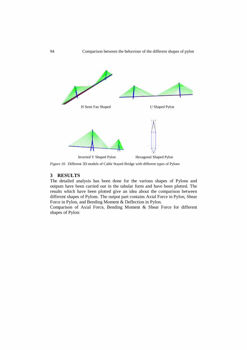
H Semi Fan Shaped U Shaped Pylon
Inverted Y Shaped Pylon Hexagonal Shaped Pylon
Figure 10. Different 3D models of Cable Stayed Bridge with different types of Pylons
3 RESULTS The detailed analysis has been done for the various shapes of Pylons and
outputs have been carried out in the tabular form and have been plotted. The results which have been plotted give an idea about the comparison between
different shapes of Pylons. The output part contains Axial Force in Pylon, Shear
Force in Pylon, and Bending Moment & Deflection in Pylon. Comparison of Axial Force, Bending Moment & Shear Force for different
shapes of Pylon:

Hararwala & Maru 95
Rectangular Concrete Pylon:
a) For Axial Force:
Graph 3.1. Comparison of axial forces for different shapes of rectangular concrete pylons
b) For Bending Moment:
Graph 3.2. Comparison of bending moments for different shapes of rectangular concrete pylons
0
1000
2000
3000
4000
5000
6000
7000
8000
Axia
l F
orc
e in
MN
Semi Fan Type
Fan Type
0
50000
100000
150000
200000
250000
300000
350000
Mom
ent in
MN
-m
Semi Fan Type
Fan Type

96 Comparison between the behaviour of the different shapes of pylon
c) For Shear Force:
Graph 3.3. Comparison of shear force for different shapes of rectangular concrete pylons
d) For Deflection at the top of Pylon:
Graph 3.4. Comparison of deflections for different shapes of rectangular concrete pylons
0
2000
4000
6000
8000
10000
12000
Forc
e in
MN
Semi Fan Type
Fan Type
0
0,1
0,2
0,3
0,4
0,5
0,6
0,7
0,8
Def
lect
ion
in m
.
Semi Fan
Fan

Hararwala & Maru 97
Circular Concrete Pylon:
a) For Axial Force:
Graph 3.5. Comparison of axial forces for different shapes of circular concrete pylons
b) For Bending Moment:
Graph 3.6. Comparison of bending moments for different shapes of circular concrete pylons
0
1000
2000
3000
4000
5000
6000
7000
8000
Axia
l F
orc
e in
MN
Semi Fan Type
Fan Type
0
50000
100000
150000
200000
250000
300000
350000
Mom
ent
in M
N-m
Semi Fan Type
Fan Type
98 Comparison between the behaviour of the different shapes of pylon
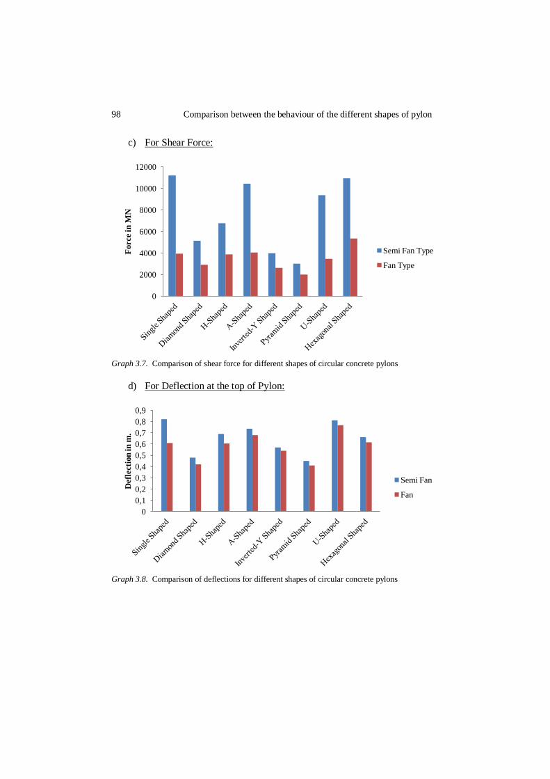
c) For Shear Force:
Graph 3.7. Comparison of shear force for different shapes of circular concrete pylons
d) For Deflection at the top of Pylon:
Graph 3.8. Comparison of deflections for different shapes of circular concrete pylons
0
2000
4000
6000
8000
10000
12000
Force in
MN
Semi Fan Type
Fan Type
0
0,1
0,2
0,3
0,4
0,5
0,6
0,7
0,8
0,9
Def
lect
ion
in m
.
Semi Fan
Fan

Hararwala & Maru 99
4 CONCLUSIONS The following points are concluded from the study undertaken:
a) For the Cable Stayed Bridge having main span of 350 m, the behaviour of
different shapes of Pylons have been studied. For the purpose of comparison between different shapes of Pylons, the single shaped Pylon has been
considered as a conventional shape of Pylon for the cable stayed bridge &
being compared with other shapes of Pylons
Comparison of Single Shaped Pylon with Diamond Shaped Pylon:
The values of axial forces in diamond shaped pylon having semi fan arrangement are 31% higher than the values in single shaped Pylon while the
pylon having fan arrangement are 22% higher values than conventional shaped
pylon.
The values of Shear force in diamond shaped Pylon are 54% less than single shaped pylon while in fan arrangement the value is 26% less.
The values of bending moment in diamond shaped pylon are 36% less than
single shaped pylon while in fan arrangement the value is 5% less. The value of deflection at the top of diamond shaped pylon is 45% less than
single shaped pylon while in fan arrangement the value is 41% less.
Comparison of Single Shaped Pylon with H-Shaped Pylon:
The values of axial forces in H-shaped pylon having semi fan arrangement are 37% higher than the values in single shaped Pylon while the pylon having fan
arrangement are 31% higher values than conventional shaped pylon.
The values of Shear force in H-shaped Pylon are 39% less than single shaped
pylon while in fan arrangement the value is 1% less. The values of bending moment in H-shaped pylon are 49% less than single
shaped pylon while in fan arrangement the value is 6% less.
The value of deflection at the top of H-shaped pylon is 19% less than single shaped pylon while in fan arrangement the value is 14% less.
Since H-Shaped pylon having twin towers so in this condition it does not
prove economical also. If the height of Pylon is more, & the forces and
moments in one of the tower of H-shaped Pylon are less than the values of pylon having single tower than it proves economical.
Comparison of Single Shaped Pylon with A-Shaped Pylon:
The values of axial forces in A-shaped pylon having semi fan arrangement are
6% lesser than the values in single shaped Pylon while the pylon having fan arrangement are 5% lesser values than conventional shaped pylon.
The values of Shear force in A-shaped Pylon are 6% less than single shaped
pylon while in fan arrangement the value is 2% higher than single shaped pylon. The values of bending moment in A-shaped pylon are 3% higher than single
shaped pylon while in fan arrangement the value is 14% high.

100 Comparison between the behaviour of the different shapes of pylon
The value of deflection at the top of A-shaped pylon is 9% less than single
shaped pylon while in fan arrangement the value is 9% less.
Similarly A-Shaped Pylon also not proves economical for such condition because it is also having two towers from the top at the either side of the deck &
it also needs excessive space for the proper clearance of deck.
Comparison of Single Shaped Pylon with Inverted-Y Shaped Pylon:
The values of axial forces in Inverted-Y shaped pylon having semi fan arrangement are 2% higher than the values in single shaped Pylon while the
pylon having fan arrangement are 3% higher values than conventional shaped
pylon.
The values of Shear force in Inverted-Y shaped Pylon are 64% less than single shaped pylon while in fan arrangement the value is 33% less.
The values of bending moment in Inverted-Y shaped pylon are 40% less than
single shaped pylon while in fan arrangement the value is 66% less. The value of deflection at the top of Inverted-Y shaped pylon is 34% less than
single shaped pylon while in fan arrangement the value is 25% less.
This Shape of Pylon also needs an excessive space for the proper clearance of deck, therefore in such conditions it does not prove economical.
Comparison of Single Shaped Pylon with Pyramid Shaped Pylon:
The values of axial forces in Pyramid shaped pylon having semi fan
arrangement are 29% lesser than the values in single shaped Pylon while the
pylon having fan arrangement are 42% lesser values than conventional shaped pylon.
The values of Shear force in Pyramid shaped Pylon are 73% less than single
shaped pylon while in fan arrangement the value is 48% less. The values of bending moment in Pyramid shaped pylon are 63% less than
single shaped pylon while in fan arrangement the value is 41% less.
The value of deflection at the top of Pyramid shaped pylon is 46% less than single shaped pylon while in fan arrangement the value is 42% less.
This shape has been introduced by connecting the twin diamonds and tying
them together at deck level a strong truss was created which transmits the
transverse wind loads to the foundations. Hence for such conditions, it provides more strength & a better aesthetical appearance.
Comparison of Single Shaped Pylon with U-Shaped Pylon:
The values of axial forces in U-shaped pylon having semi fan arrangement are
37% higher than the values in single shaped Pylon while the pylon having fan arrangement are 28% higher values than conventional shaped pylon.
The values of Shear force in U-shaped Pylon are 16% less than single shaped
pylon while in fan arrangement the value is 11% less.
The values of bending moment in U-shaped pylon are 30% less than single shaped pylon while in fan arrangement the value is 6% less.

Hararwala & Maru 101
The value of deflection at the top of U-shaped pylon is 5% less than single
shaped pylon while in fan arrangement the value is 6% less.
Comparison of Single Shaped Pylon with Hexagonal Shaped Pylon:
The values of axial forces in Hexagonal shaped pylon having semi fan arrangement are 2% higher than the values in single shaped Pylon while the
pylon having fan arrangement are 2% higher values than conventional shaped
pylon. The values of Shear force in hexagonal shaped Pylon are 2% less than single
shaped pylon while in fan arrangement the value is 35% less.
The values of bending moment in hexagonal shaped pylon are 54% less than
single shaped pylon while in fan arrangement the value is 23% less. The value of deflection at the top of hexagonal shaped pylon is 19% less than
single shaped pylon while in fan arrangement the value is 9% less.
From the results, it has been concluded that the Pyramid Shaped Pylon having the minimum value of axial forces, bending moment, shear force &
deflection in such conditions for Cable Stayed Bridge.
b) The fan arrangement of cables gives the 5% higher values of axial force, 22% lesser values of Bending moment, 49% lesser values of Shear force &
9% lesser value of deflection than the value of axial force, bending
moment, shear force & deflection in semi fan type arrangement. But when the fan arrangement considered for long spans, the size of the cables
increased, which proves uneconomically large and difficult to adapt within
the fan configuration. The anchorages were also substantial and more complex and the deck needed to be further become stronger at the ending
point. Therefore when lot of cable stays were required then the semi fan
layout must be opted. For much better results the spacing of cable stays
which were tied at pylon should be kept at minimum. c) The cross section of Pylon must be kept rectangular as the stresses in
circular sections are greater than rectangular. And also for ease in
construction of complex forms of Pylons such as Diamond shaped, Pyramid Shaped, A-shaped, Inverted-Y shaped rectangular pylon proves
economical and can easily be constructed.
d) The moments, forces & deflections developed in Hexagonal Shaped Pylon and U-shaped Pylon are not as much higher than other suitable shapes of
pylons. Hence both shapes can be implemented in actual practice after the
proper experimental verification on such shapes in severe conditions.
These conclusions are based on the results of models which were prepared and analyzed using SAP2000 software.
5 REFERENCES [1] Airong CHEN, Qingzhong YOU, Xigang ZHANG, Rujin MA, Zhiyong ZHOU (2005), “The
102 Comparison between the behaviour of the different shapes of pylon
Study of Aerodynamic Problems of a Super Long Span Cable Stayed Bridge.” [2] Atul K. Desai 2013, “Siesmic Time History Analysis for Cable Stayed Bridges considering
different geometrical configuration for near field earthquakes”, Volume 7
[3] A.M.S. Freirea, J.H.O. Negraob, A.V. Lopesb (2006), “The Geometrical Nonlinearities on the Static Analysis of Highly Flexible Steel Cable Stayed Bridges.”
[4] Bruno D., Grimaldi A., “Non Linear Behaviour of Long Span Cable Stayed Bridges”, Meccanica, Vol 20 1985.
[5] Chatterjee, Datta and Surana (1994), “A Continuum Approach for Analyzing the Dynamic Response of Cable Stayed Bridges.”
[6] CSI Bridge Key Manual, Computers and Structures. [7] Domenico Bruno, Fabrizio Greco, Paolo Lonetti 2013, “Static and Dynamic NonLinear
Modelling of Long Span Cable Stayed Bridges”, IJBE VOLUME 1. [8] Dr. N D Shah, Dr. J A Desai & Dr. H.S. Patil 2011, “Effect of Pylon Shape on Analysis of
Cable Stayed Bridge”, ISSN: 0976-7916 Volume-2 JERs. [9] D. J. Farquhar, Mott Macdonald, “ICE Manual 13 Cable Stayed Bridges” Institute of Civil
Engineers 2008. [10] Fleming & Egeseli (1980) [21, 22], “Comparison between Linear and Non Linear Dynamic
Analysis Results for a Cable Stayed Bridge Subjected to Seismic and Wind Forces.” [11] Fleming J.F., “Nonlinear Static Analysis of Cable Stayed Bridges”, Computers & Structures
1979. [12] Ghanshyam M. Savaliya1, Atul K Desai2 and Sandip A Vasanwala3 (2012), “The Effects of
Side Span Supports on the Behaviour of Long Span Cable Stayed Bridge. [13] Midas Civil Tutorials, “Modelling & Analysis of Cable Stayed Bridges”. [14] N D Shah & Dr. J A Desai 2010, “Nonlinear Aerostatic Analysis of Self Anchored & Bi-
stayed Cable Stayed Bridges using sap 2000”, ISSN: 0975-6744 Volume 1, Issue 1. [15] Olfat Sarhang Zadeh 2012, “Comparison between three types of Cable Stayed Bridges using
Structural Optimisation”, M.E. thesis, School of Graduate and Postdoctoral Studies,The University of Western Ontario London, Ontario, Canada.
[16] Prof. Dr. Ing. Wang, Pao-Hsii (2009), “Structural Behaviour of Cable Stayed Bridges Including the Interaction of Cable Stays and the Bridge.”
[17] Roland (2000), “The Effect of Cables due to Deterioration in Cable Stayed Bridge.” [18] SAP Tutorials, “Modelling & Analysis of Cable Stayed Bridges.” [19] SAP2000. “Structural Analysis Programme” Integrated finite element analysis and design of
structures. Computers and Structures. [20] Seong-Ho Kim1, Joo-Taek Park2 and Kyoung-Jae Lee3 (2009), “The Study of Aerodynamic
Stabilizing for Tangential and Curved Cable Stayed Bridge Under Construction.”
[21] Siddharth G. Shah, Desai.J.A & Solanki.C.H 2010, “Effect of Pylon Shape on seismic response of Cable stayed bridge with soil structure interaction”, ISSN: 0976-4399 Volume 1, Issue 3.
[22] Simoes and Negrao (2000) had employed “Optimization in the Cost of the Deck in Cable-Stayed Bridges.”
[23] Starossek U. (1996), ―Cable Stayed Bridge Concept of Longer Spans, Journal of Bridge Engg., Aug, Vol-1, 99-103.
[24] Sung Et Al (2006), “Optimum Post Tensioning Forces in Cables of Cable Stayed Bridge in
Various Conditions of Loads.” [25] Vikas A C, Prashanth M H, Indrani Gogoi, Channappa T M1 (2013), “The Effect of Cable
Degradation.” [26] Wilson J. C. and Gravelle W. (1991) “Modelling Of A Cable-Stayed Bridge For Dynamic
Analysis” Earthquake Engineering And Structural Dynamics, Volume 20, Issue 1. [27] Xu Xie, Xiaozhang and Yonggang Shen (2014), “Static and Dynamic Characteristics of a
Long Span Cable Stayed Bridge which is made up of CFRP (Carbon Fibre Reinforced Plastic) Cables.”