Embed Size (px)
Citation preview

Bjørnafjorden Suspension Bridge K1 & K2 Cable system design
0 30.06.2016 For commenting JESO TOF KAA
Rev Dato/Date Beskrivelse/Reason for issue Utført/
Made by
Kontr./
Checked
Godkjent/
Approved
Tittel /Title
Dok.nr /Doc. no.
K1 & K2 Cable system design
SBT-PGR-PP-211-013-A
Lilleakerveien 4A, 0283 OSLO, Tel +47 22 51 30 00 Fax +47 22 51 30 01

Lilleakerveien 4A 0283 OSLO Norway
Tel. +47 22 51 30 00 Fax +47 22 51 30 01
Dok.nr./Doc.no
SBT-PGR-PP-211-013
Rev.
0
Prosjekt/Project Dato/Date Rev.dato/Date
Bjørnafjorden suspension bridge 17.06.16
Tittel / Title Utført/Prep.By Rev. av/Rev by Side/Page
K1 & K2 Cable system design JESO i
LIST OF REVISIONS
Rev Revised
0 First Issue
Rev Date
Report (incl. Appendices A-F) 0 30.06.2016

Lilleakerveien 4A 0283 OSLO Norway
Tel. +47 22 51 30 00 Fax +47 22 51 30 01
Dok.nr./Doc.no
SBT-PGR-PP-211-013
Rev.
0
Prosjekt/Project Dato/Date Rev.dato/Date
Bjørnafjorden suspension bridge 17.06.16
Tittel / Title Utført/Prep.By Rev. av/Rev by Side/Page
K1 & K2 Cable system design JESO ii
TABLE OF CONTENTS
LIST OF REVISIONS ........................................................................................................................................................ I
TABLE OF CONTENTS ................................................................................................................................................. II
SUMMARY ...................................................................................................................................................................... IV
1 INTRODUCTION .................................................................................................................................................... 1
1.1 GENERAL ............................................................................................................................................................... 1 1.2 CODES AND DESIGN MEMORANDUM ....................................................................................................................... 1 1.3 DRAWINGS ............................................................................................................................................................. 2
2 SUSPENDED CABLE ............................................................................................................................................. 3
2.1 GEOMETRY ............................................................................................................................................................ 3 2.2 CALCULATION ........................................................................................................................................................ 3
2.2.1 Materials and partial factors ....................................................................................................................... 3 2.2.2 Model and loads .......................................................................................................................................... 4 2.2.3 Cable Area and diameter ............................................................................................................................. 8 2.2.4 Cable wire pressure ..................................................................................................................................... 9
2.3 EXECUTION ...........................................................................................................................................................12
3 TOP CABLES .........................................................................................................................................................13
3.1 TOP CABLE SAG AND SIZE ......................................................................................................................................13 3.2 LOADS ...................................................................................................................................................................14 3.3 ANCHORAGE AT STEEL TOWER - LAYOUT ..............................................................................................................17 3.4 ANCHORAGE AT CONCRETE TOWER - LAYOUT .......................................................................................................18 3.5 ALTERNATIVE TOP CABLE SYSTEM ........................................................................................................................20
3.5.1 Anchorages .................................................................................................................................................21 3.6 INSTALLATION AND CONSTRUCTABILITY ..............................................................................................................23 3.7 DURABILITY ..........................................................................................................................................................25
4 HANGERS ...............................................................................................................................................................26
4.1 FUNCTIONALITY ....................................................................................................................................................26 4.2 PARTICULARS........................................................................................................................................................26 4.3 GEOMETRY ...........................................................................................................................................................26 4.4 MATERIALS ...........................................................................................................................................................28 4.5 LOADS ...................................................................................................................................................................28 4.6 VERIFICATION .......................................................................................................................................................30
4.6.1 Hanger strand .............................................................................................................................................30 4.6.2 Pin ...............................................................................................................................................................31
4.7 HANGER ROTATIONS .............................................................................................................................................34 4.7.1 Service loads ...............................................................................................................................................34
5 CABLE CLAMPS ...................................................................................................................................................37
5.1 GEOMETRY ...........................................................................................................................................................37 5.2 MATERIALS ...........................................................................................................................................................37 5.3 LOADS ...................................................................................................................................................................38 5.4 VERIFICATION .......................................................................................................................................................38
6 PYLON SADDLES .................................................................................................................................................40
6.1 INTRODUCTION .....................................................................................................................................................40 6.2 GEOMETRY ...........................................................................................................................................................40
6.2.1 Materials .....................................................................................................................................................41

Lilleakerveien 4A 0283 OSLO Norway
Tel. +47 22 51 30 00 Fax +47 22 51 30 01
Dok.nr./Doc.no
SBT-PGR-PP-211-013
Rev.
0
Prosjekt/Project Dato/Date Rev.dato/Date
Bjørnafjorden suspension bridge 17.06.16
Tittel / Title Utført/Prep.By Rev. av/Rev by Side/Page
K1 & K2 Cable system design JESO iii
6.3 VERIFICATION .......................................................................................................................................................42 6.3.1 Pressure distribution...................................................................................................................................42 6.3.2 Wires ...........................................................................................................................................................43 6.3.3 Trough bottom ............................................................................................................................................43 6.3.4 Trough sides................................................................................................................................................44 6.3.5 Support ribs ................................................................................................................................................45 6.3.6 Central plate ...............................................................................................................................................46
7 SPLAY SADDLES ..................................................................................................................................................47
7.1 INTRODUCTION .....................................................................................................................................................47 7.2 GEOMETRY ...........................................................................................................................................................47
7.2.1 Material ......................................................................................................................................................47 7.3 VERIFICATION .......................................................................................................................................................48

Lilleakerveien 4A 0283 OSLO Norway
Tel. +47 22 51 30 00 Fax +47 22 51 30 01
Dok.nr./Doc.no
SBT-PGR-PP-211-013
Rev.
0
Prosjekt/Project Dato/Date Rev.dato/Date
Bjørnafjorden suspension bridge 17.06.16
Tittel / Title Utført/Prep.By Rev. av/Rev by Side/Page
K1 & K2 Cable system design JESO iv
SUMMARY
The Bjørnafjorden Suspension bridge cable system has been verified in the present report
documenting the overall capacity of the following structures:
Suspended cable
Top cable (incl. anchorages)
Saddles
hangers
cable clamp
The verification is based on forces extracted from the project global FE model made in the FE
program RM Bridge and Orcaflex (waves).
It has been concluded that the cable system has sufficient capacity to overcome the load scenarios
that might occur in the Bjørnafjordan in respect to both wind, wave and traffic loadings combined.
Also the design of the cable system in terms of constructability has been considered. Here it is found
that when the top cables are installed on the bridge conventional methods can be used for the
construction of the remaining parts of the cable system making the design feasible.
Lilleakerveien 4A 0283 OSLO Norway
Tel. +47 22 51 30 00 Fax +47 22 51 30 01
Dok.nr./Doc.no
SBT-PGR-PP-211-013
Rev.
0
Prosjekt/Project Dato/Date Rev.dato/Date
Bjørnafjorden suspension bridge 17.06.16
Tittel / Title Utført/Prep.By Rev. av/Rev by Side/Page
K1 & K2 Cable system design JESO 1
1 INTRODUCTION
1.1 General
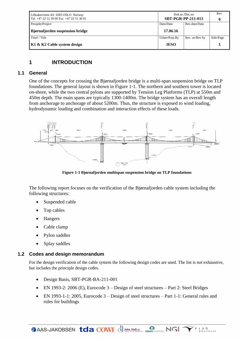
One of the concepts for crossing the Bjørnafjorden bridge is a multi-span suspension bridge on TLP
foundations. The general layout is shown in Figure 1-1. The northern and southern tower is located
on-shore, while the two central pylons are supported by Tension Leg Platforms (TLP) at 550m and
450m depth. The main spans are typically 1300-1400m. The bridge system has an overall length
from anchorage to anchorage of about 5200m. Thus, the structure is exposed to wind loading,
hydrodynamic loading and combination and interaction effects of these loads.
Figure 1-1 Bjørnafjorden multispan suspension bridge on TLP foundations
The following report focuses on the verification of the Bjørnafjorden cable system including the
following structures:
Suspended cable
Top cables
Hangers
Cable clamp
Pylon saddles
Splay saddles
1.2 Codes and design memorandum
For the design verification of the cable system the following design codes are used. The list is not exhaustive,
but includes the principle design codes.
Design Basis, SBT-PGR-BA-211-001
EN 1993-2: 2006 (E), Eurocode 3 – Design of steel structures – Part 2: Steel Bridges
EN 1993-1-1: 2005, Eurocode 3 – Design of steel structures – Part 1-1: General rules and
rules for buildings

Lilleakerveien 4A 0283 OSLO Norway
Tel. +47 22 51 30 00 Fax +47 22 51 30 01
Dok.nr./Doc.no
SBT-PGR-PP-211-013
Rev.
0
Prosjekt/Project Dato/Date Rev.dato/Date
Bjørnafjorden suspension bridge 17.06.16
Tittel / Title Utført/Prep.By Rev. av/Rev by Side/Page
K1 & K2 Cable system design JESO 2
EN 1993-1-5: 2006, Eurocode 3 – Design of steel structures – Part 1-5: Plated structural
elements
EN 1993-1-8: 2005, Eurocode 3 – Design of steel structures – Part 1-8: Design of joints
1.3 Drawings
The following project drawings is the basis for the calculations
Drawing Title Drawing Number
Bjørnafjorden suspension bridge - SBT-PGR-DR-211-
K1 & K2 cable structures - Suspended Cables 501
K1 & K2 cable structures - Hangers 502
K1 & K2 cable structures - Cable clamp 503
K1 & K2 cable structures - Top cable and top cable anchorage 504
K1 & K2 cable structures - Pylon saddles axis 4 & 7 505
K1 & K2 cable structures - Pylon saddles axis 5 & 6 506
K1 & K2 cable structures - Splay saddle 507
K1 & K2 cable structures - Splay saddle - Setting out 508
Lilleakerveien 4A 0283 OSLO Norway
Tel. +47 22 51 30 00 Fax +47 22 51 30 01
Dok.nr./Doc.no
SBT-PGR-PP-211-013
Rev.
0
Prosjekt/Project Dato/Date Rev.dato/Date
Bjørnafjorden suspension bridge 17.06.16
Tittel / Title Utført/Prep.By Rev. av/Rev by Side/Page
K1 & K2 Cable system design JESO 3
2 SUSPENDED CABLE
This chapter comprises a brief description of the suspended cables and their functionality supported
by results of the analyses and calculations made for the detailed design documentation of the
structures.
2.1 Geometry
The cable system for the suspension bridge comprises of two suspended cables and is designed with
a skew cable plan, which are inclined towards the bridge girder, which gives an individual angle for
all hangers in a span.
The suspended cables are erected using the Parallel Wire Strand (PWS) method and each PWS
consists of 127 no 5.15 mm diameter wires, stretching from the north anchorage to the south
anchorage. Each suspended cable is between 0.605m (main span) - 0.655m (side span) diameter
once compacted (20% air void). A contractor’s review of construction aspects suggests that a
solution using 91 wires per cable strand may be adopted in order to limit the weight.
Alternative erection of the suspended cable by air spinning is also a possibility.
The majority of strands run for the full length of the suspended cable, from anchorage to anchorage,
however due to the choice of not having top cables in the side spans the side span suspended cables
are provided with 15 additional strands each.
As backup for the top cables these additional strands in the side span likely needs to be erected
before the continuous strands.
The sag to span ratio for the suspended span is approximately 1:10, however it is recommendable to
study an optimisation using a ratio of approximately 1:9.. The suspended cables are protected by S-
formed wrapping wire, paint and a state-of-the-art dehumidification system.
The suspended cables are supported at the towers and anchorages by saddles.
At their ends, the suspended cable PWS are considered fixed to the anchor blocks by tie rods bolted
into cross head slabs. These cross head slabs provide an integral anchorage for the post-tensioned
tendons that stress the cross head slabs against the concrete surface and transfer the suspended cable
tension into the concrete anchor block.
Hangers and cable clamps are typically installed at 24 m intervals introducing a local kink in the
cable. Each clamp supports a single PE sheathed locked coil (LC) hanger strand.
2.2 Calculation
2.2.1 Materials and partial factors
The suspended cables shall be formed of PWS, each of which is initially fabricated with a fixed
number of wires in a regular hexagonal formation. The selected wire characteristics are summarised
below:

Lilleakerveien 4A 0283 OSLO Norway
Tel. +47 22 51 30 00 Fax +47 22 51 30 01
Dok.nr./Doc.no
SBT-PGR-PP-211-013
Rev.
0
Prosjekt/Project Dato/Date Rev.dato/Date
Bjørnafjorden suspension bridge 17.06.16
Tittel / Title Utført/Prep.By Rev. av/Rev by Side/Page
K1 & K2 Cable system design JESO 4
Table 2-1: Characteristics of the suspended cable wire:
Parameter Value
Ultimate tensile strength (fu) 1860 MPa
Young's' Modulus 200 GPa
Wire diameter 5.15 mm
The partial factors are:
› Partial material factor for ULS STR verifications γm = 1.80
› Partial material factor for SLS verifications γm = 2.20
› Partial material factor for ULS Accidental loading situations γm = 1.40
2.2.2 Model and loads
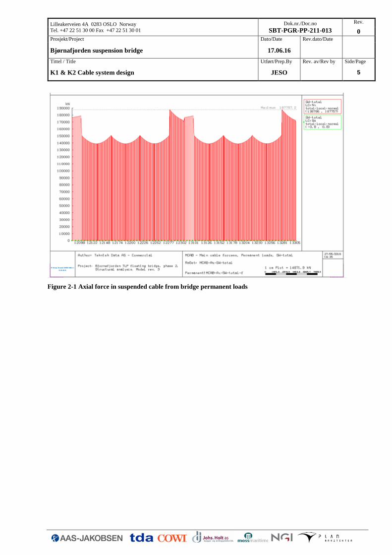
The following figures are plots from the RM Bridge model showing the axial force in the suspended
cable for key loads in the reference condition. The term reference condition here represents the
condition at day of completion for the bridge loaded with all permanent loads (structural + non-
structural dead loads).
The figures show the axial force in both cables and it can be seen that generally the force distribution
is symmetric, however for traffic + walkway loading the axial force is higher in one cable, which is
due to that the bridge girder only has a walkway on one side.
Lilleakerveien 4A 0283 OSLO Norway
Tel. +47 22 51 30 00 Fax +47 22 51 30 01
Dok.nr./Doc.no
SBT-PGR-PP-211-013
Rev.
0
Prosjekt/Project Dato/Date Rev.dato/Date
Bjørnafjorden suspension bridge 17.06.16
Tittel / Title Utført/Prep.By Rev. av/Rev by Side/Page
K1 & K2 Cable system design JESO 5
Figure 2-1 Axial force in suspended cable from bridge permanent loads

Lilleakerveien 4A 0283 OSLO Norway
Tel. +47 22 51 30 00 Fax +47 22 51 30 01
Dok.nr./Doc.no
SBT-PGR-PP-211-013
Rev.
0
Prosjekt/Project Dato/Date Rev.dato/Date
Bjørnafjorden suspension bridge 17.06.16
Tittel / Title Utført/Prep.By Rev. av/Rev by Side/Page
K1 & K2 Cable system design JESO 6
Figure 2-2 Axial force in suspended cable from traffic and walkway loads

Lilleakerveien 4A 0283 OSLO Norway
Tel. +47 22 51 30 00 Fax +47 22 51 30 01
Dok.nr./Doc.no
SBT-PGR-PP-211-013
Rev.
0
Prosjekt/Project Dato/Date Rev.dato/Date
Bjørnafjorden suspension bridge 17.06.16
Tittel / Title Utført/Prep.By Rev. av/Rev by Side/Page
K1 & K2 Cable system design JESO 7
Figure 2-3 Axial force in suspended cable from wind (100 year return period)
Using the load combinations stated in the design basis the maximum cable force can be determined
based on the individual loads reported in the figures above, refer Table 2-2.
Table 2-2 Maximum forces in suspended cable [MN]
Location ULS [MN] SLS [MN]
Side Spans 274.1 224.3
Central Spans 218.1 177.4
The difference in cable force between side spans and central spans is mainly due to the fact that the
top cables are not continued in the side span, but 15 additional strands have been added in the
suspended cable instead to compensate for this effect, refer also section 2.2.3 and section 3.
It should be noted that the maximum cable force in the central span is calculated to 218MN, but in
the verification of saddles in section 6 and section 7 a force of 220MN has been used. This is due to
a late change in the model resulting in a slightly lower cable force, however it has not been found

Lilleakerveien 4A 0283 OSLO Norway
Tel. +47 22 51 30 00 Fax +47 22 51 30 01
Dok.nr./Doc.no
SBT-PGR-PP-211-013
Rev.
0
Prosjekt/Project Dato/Date Rev.dato/Date
Bjørnafjorden suspension bridge 17.06.16
Tittel / Title Utført/Prep.By Rev. av/Rev by Side/Page
K1 & K2 Cable system design JESO 8
necessary to update the calculations and the determined dimensions for the saddle structures are still
considered acceptable.
The cable force does not account for 2nd order effects which will require a full non-linear analysis.
The 2nd order effects are likely to reduce the cable force with 1-2%, which thus is not accounted for
in the following design.
Also special situations as free hanging cables, cable rotation, secondary stresses and displacement at
saddles have not been considered at this stage of the project. A fatigue calculation has also not been
performed, but based on experience this is not foreseen to have any influence on the suspended cable
dimensions.
2.2.3 Cable Area and diameter
As it can be seen from the previous figures the force in the suspended cable varies from main to side
span. The large difference in force is primarily due to the unconventional cable system having top
cables between the towers, refer section 3. The top cables are however not continued in the side
spans meaning that this additional force needs to be transferred in the suspended cable at this
location. Therefore it has been determined that 15 additional strands are necessary in the side spans
to compensate for the lack of top cables resulting in a different cable area and force.
In the following the cable area and diameter is determined. Due to the partial factors SLSc is found
to be the governing case.
Central spans:
𝐴𝑀,𝑆𝐿𝑆𝑐 = 𝑁 𝜎⁄ = 177.4MN/ (1860MPa 2.2⁄ ) = 0.209m2
𝐴𝑀,𝑈𝐿𝑆𝑠𝑡𝑟 = 𝑁 𝜎⁄ = 218.1MN/ (1860MPa 1.8)⁄ = 0.211m2
Side spans:
𝐴𝑀,𝑆𝐿𝑆𝑐 = 𝑁 𝜎⁄ = 224.3MN/ 1860MPa 2.2⁄ = 0.265m2
𝐴𝑀,𝑈𝐿𝑆𝑠𝑡𝑟 = 𝑁 𝜎⁄ = 274.1MN/ 1860MPa 1.8⁄ = 0.265m2
The main span cable consists of 87 strands of each 127 No 5.15 mm diameter wires giving an area of
𝐴𝑀 = 𝜋 4⁄ ∙ (5.15𝑚𝑚)2 ∙ 127 ∙ 87 = 0.23𝑚2 , satisfactory
With 15 additional strands in the side span the side span cable has an area of
𝐴𝑆 = 𝜋 4⁄ ∙ (5.15𝑚𝑚)2 ∙ 127 ∙ 102 = 0.27𝑚2, satisfactory

Lilleakerveien 4A 0283 OSLO Norway
Tel. +47 22 51 30 00 Fax +47 22 51 30 01
Dok.nr./Doc.no
SBT-PGR-PP-211-013
Rev.
0
Prosjekt/Project Dato/Date Rev.dato/Date
Bjørnafjorden suspension bridge 17.06.16
Tittel / Title Utført/Prep.By Rev. av/Rev by Side/Page
K1 & K2 Cable system design JESO 9
Figure 2-4 Cross section in main and side span. Additional strands marked in grey.
With an assumed air void ratio of 20 % after compaction the diameter in the main span is:
𝐷0.20,𝐻 = √4
𝜋∙
0. 23𝑚2
0.80= 605𝑚𝑚
In the side span:
𝐷0.20,𝐾 = √4
𝜋∙
0.27𝑚2
0.80= 655𝑚𝑚
2.2.4 Cable wire pressure
In area where the prefabricated suspended cable is subjected to radial pressure due to curvature of
saddles or pressure from the cable clamps the effect needs to be considered.
The allowable lateral pressure on the suspended cable is defined to:
2.2.4.1.1.1.1.1 𝐹𝑡𝑣æ𝑟 = 0.60𝑀𝑁/𝑚 per wire)
Since the suspended cable is almost equally utilised in the main and side spans the force in each of
the 87 strands will be the same. The ULS-force in a single wire can thus be calculated to using a
cable force of F=220MN:
𝐹𝑤𝑖𝑟𝑒 = 220𝑀𝑁/(87 ∙ 127) = 0.02𝑀𝑁
2.2.4.2 Pylon saddles
The tower saddles are constructed with a radius of the trough bottom plate approximately 5.2-5.7m,
refer section 6. The shape of the individual strands within in the saddle trough is rectangular with
BxH = 10 - 11 x 12 wires for stands consisting of 127 wires.

Lilleakerveien 4A 0283 OSLO Norway
Tel. +47 22 51 30 00 Fax +47 22 51 30 01
Dok.nr./Doc.no
SBT-PGR-PP-211-013
Rev.
0
Prosjekt/Project Dato/Date Rev.dato/Date
Bjørnafjorden suspension bridge 17.06.16
Tittel / Title Utført/Prep.By Rev. av/Rev by Side/Page
K1 & K2 Cable system design JESO 10
Figure 2-5 Suspended cable geometry in Pylon saddles (Axix 5 & 6 shown)
In the following the pressure on the critical bottom wire in the saddle is calculated. It is
conservatively assumed that there will be no redistribution of pressure such that the strand in one
saddle grove will have to be distributed over the bottom 11 wires including 10mm from the
separation plates between each groove, refer Figure 2-5.
The central groove has 11 layers of strands and thereby the radial pressure on the bottom wires can
be calculated accounting for the saddle curvature to:
𝑃𝑣 = 11 ∙ 0.02𝑀𝑁 5.2𝑚⁄ = 0.044𝑀𝑁 𝑚⁄ /𝑡𝑟å𝑑
The pressure on the bottom wire can thus be calculated to:
𝑃𝑣 ∙ 11 = 0.49𝑀𝑁/𝑚 < 0.60𝑀𝑁/𝑚
2.2.4.3 Splay saddles
In a similar manner as for the tower saddle the radial pressure can be determined for the splay
saddle. The splay saddle will be constructed with varying radius of the trough bottom, however
where all strands are active the vertical radius is R=7m. Besides the vertical distribution also the
horizontal distribution with different radii will give pressure to the suspended cable, however only in
the outer grooves.

Lilleakerveien 4A 0283 OSLO Norway
Tel. +47 22 51 30 00 Fax +47 22 51 30 01
Dok.nr./Doc.no
SBT-PGR-PP-211-013
Rev.
0
Prosjekt/Project Dato/Date Rev.dato/Date
Bjørnafjorden suspension bridge 17.06.16
Tittel / Title Utført/Prep.By Rev. av/Rev by Side/Page
K1 & K2 Cable system design JESO 11
Figure 2-6 Suspended cable geometry in Splay saddles
Due to the additional strands in the side span there are 12 strands in the central groove. Since each
wire carry the force of 0.02MN and R=7m the radial pressure becomes:
𝐹 = 12 ∙ 0.02𝑀𝑁 (7𝑚 − 0.29𝑚)⁄ = 0. 036𝑀𝑁/ 𝑚 / 𝑡𝑟å𝑑
The pressure on the bottom wire can thus be calculated to:
𝑃𝑣 ∙ 11 = 0.44𝑀𝑁/𝑚 < 0.60𝑀𝑁/𝑚
The pressure on the wires in the outer grooves are also affected by the horizontal spread in the
saddle. Here the horizontal radius is 12.5m. This pressure shall be added to the simultaneous radial
pressure, however due to the large radius and fewer strands in the outer groove and fewer strands
curved horizontally than vertically this pressure will be smaller, and is thus not calculated in detail
here. Reference is made to Appendix F.
It is also examined if there is a risk that the top strands will try to deform due to the horizontal
curvature of the saddle. From the following figure it can be seen that to ensure that the individual
threads do not start to role the downwards pressure shall be 1.73 times the horizontal pressure – or in
other words the vertical radius shall be 1.73 time less that the horizontal radius.
For the splay saddle the following applies:
Lilleakerveien 4A 0283 OSLO Norway
Tel. +47 22 51 30 00 Fax +47 22 51 30 01
Dok.nr./Doc.no
SBT-PGR-PP-211-013
Rev.
0
Prosjekt/Project Dato/Date Rev.dato/Date
Bjørnafjorden suspension bridge 17.06.16
Tittel / Title Utført/Prep.By Rev. av/Rev by Side/Page
K1 & K2 Cable system design JESO 12
12500
7000= 1.79 ≥ 1.73, 𝑂𝐾
No friction has been accounted for.
2.2.4.4 Cable clamps
The pressure on the suspended cable from cable clamps may not exceed 12MPa.
The bolts in the cable clamps are pre-tensioned to a force of 0.54MN each. Having 12 bolts on a
900mm long clamp this force needs to be distributed to an area of 0.303m x 0.15m = 0.0455m2,
which results in a cable pressure of:
0.55𝑀𝑁 0.0455𝑚2⁄ = 11.9𝑀𝑃𝑎 < 12𝑀𝑃𝑎
The pre-tensioned force is thus found acceptable.
2.3 Execution
The suspended cable is executed by pulling full pre-fabricated strands one by one from one anchor
block to the other. This is done placing the strand on a roller using the pre-installed catwalk.
However the inclined cable plan makes the construction of the cable slightly different from
conventional methods used for a vertical suspended cable. However it is assessed that the
fundamentals will not change significantly so the different construction procedures remain more or
less the same.
Also Air spinning will be a possibility for the suspended cable.
It is assumed that the cable will be constructed in a vertical plane, the cable clamps are installed and
the cable is pushed to its final position either by installation of the deck segments starting at centre
span or by using adjustable compression bars. Thus meaning that the cable clamps will be rotated
naturally to fit with their final position.
It will also be possible to erect the bridge girder elements from the pylons and outwards, by which
the suspended cable may not need to be pushed apart beforehand.

Lilleakerveien 4A 0283 OSLO Norway
Tel. +47 22 51 30 00 Fax +47 22 51 30 01
Dok.nr./Doc.no
SBT-PGR-PP-211-013
Rev.
0
Prosjekt/Project Dato/Date Rev.dato/Date
Bjørnafjorden suspension bridge 17.06.16
Tittel / Title Utført/Prep.By Rev. av/Rev by Side/Page
K1 & K2 Cable system design JESO 13
3 TOP CABLES
The following chapter addresses various issues with the current design of the Bjørnafjorden
suspension bridge TLP concept in terms of choice of top cables system.
The original design concept for Bjørnefjorden was very much similar to that of a conventional
suspension bridge using central locks to distribute movements equally to the bridge ends. However
there has been a lack of in-plane stability in the original system leading to large vertical
displacement of the deck. To accommodate this effect top cables have been introduced between
pylon tops preventing these from excessive in-plane deformations and thereby also limiting the deck
displacement. In the present note the different concepts considered for the top cable system is
outlined.
For the current design concept of the Bjørnafjorden suspension bridge top cables are not continued
in the side spans, but additional strands in the suspended cable has been introduced.
3.1 Top cable sag and size
Considering constructability, geometrical constraints and aesthetics it is decided to design the top
cable as a number of smaller cables. The top cable system can be arranged as 10 individual cables
anchored at each pylon top and at anchor blocks. In order to provide initial stiffness to the bridge
system the top cables are pre-stressed to around 0.45GUTS. Having an ultimate strength of
1860MPa a pre-tension force of 800MPa is used.
In order to determine the appropriate size of the cables a parametric study has been performed to see
the impact in choice of the total top cable area. The following impact scenarios has been considered:
Deck displacement
Deck bending moment at tower/mid span
Bending moment tower footing
A full bridge analysis has been performed in the FE program IBDAS where the top cable area has
been changed to compare the result on the structural response. In the below table three choices of
cable size is given and their subsequent effect on the structural behaviour.
Table 3-1 Top cable – Area impact study
Top Cables Area 0.05 [m2] 0.081 [m2] 0.10 [m2]
Displacement – Deck (max) U [m] 10.6 8.9 8.3
Displacement – Tower top U [m] 4.1 3.2 2.8
Deck Moment – Mid span My [MNm] 84.1 83.4 83.3
Tower Moment - Footing My [MNm] -1243 -1046 -967
Mz [MNm] 3301 3166 3082
Lilleakerveien 4A 0283 OSLO Norway
Tel. +47 22 51 30 00 Fax +47 22 51 30 01
Dok.nr./Doc.no
SBT-PGR-PP-211-013
Rev.
0
Prosjekt/Project Dato/Date Rev.dato/Date
Bjørnafjorden suspension bridge 17.06.16
Tittel / Title Utført/Prep.By Rev. av/Rev by Side/Page
K1 & K2 Cable system design JESO 14
As it can be seen from the table there is significanteffects on the structural displacements and on the
tower bending moment My, being in the bridge longitudinal direction. This is also what was to be
expected since the top cables primarily contributes to a more stiff system in the bridge longitudinal
direction limiting the tower top movement.
It can be noted that the change in area going from 0.05m2 to 0.08m2 has around twice as large
impact than from 0.08 m2 to 0.1 m2 both in respect to displacement and force. Since the change in
sectional forces for the suspended deck is limited and the towers are highly governed by axial force,
which will more or less be unaffected by change in top cable area, the governing parameter will be
displacement. The small saving achievable in tower steel due to the change in bending moment will
not be comparable with the much more expensive cable steel. However to limit the deflection of the
suspended deck will require a significant quantity increase in deck steel compared to the top cable,
thus considering the deck displacement a top cable area of 0.081m2 is chosen at this stage of the
design.
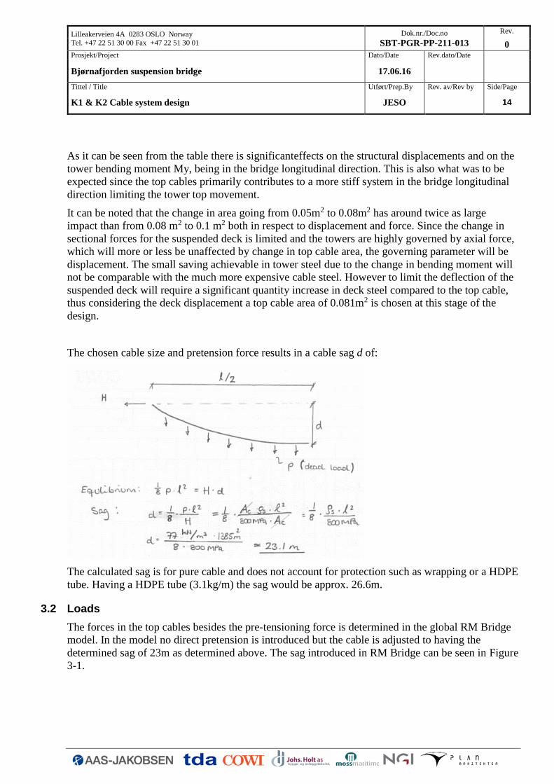
The chosen cable size and pretension force results in a cable sag d of:
The calculated sag is for pure cable and does not account for protection such as wrapping or a HDPE
tube. Having a HDPE tube (3.1kg/m) the sag would be approx. 26.6m.
3.2 Loads
The forces in the top cables besides the pre-tensioning force is determined in the global RM Bridge
model. In the model no direct pretension is introduced but the cable is adjusted to having the
determined sag of 23m as determined above. The sag introduced in RM Bridge can be seen in Figure
3-1.

Lilleakerveien 4A 0283 OSLO Norway
Tel. +47 22 51 30 00 Fax +47 22 51 30 01
Dok.nr./Doc.no
SBT-PGR-PP-211-013
Rev.
0
Prosjekt/Project Dato/Date Rev.dato/Date
Bjørnafjorden suspension bridge 17.06.16
Tittel / Title Utført/Prep.By Rev. av/Rev by Side/Page
K1 & K2 Cable system design JESO 15
Figure 3-1 Introduced sag of top cables in the RM bridge model.
The top cable forces (nominal values) are reported in Figure 3-2 to Figure 3-4.
Figure 3-2 Force in top cable – Pre-tensioning (Permanent loading)

Lilleakerveien 4A 0283 OSLO Norway
Tel. +47 22 51 30 00 Fax +47 22 51 30 01
Dok.nr./Doc.no
SBT-PGR-PP-211-013
Rev.
0
Prosjekt/Project Dato/Date Rev.dato/Date
Bjørnafjorden suspension bridge 17.06.16
Tittel / Title Utført/Prep.By Rev. av/Rev by Side/Page
K1 & K2 Cable system design JESO 16
Figure 3-3 Force in top cable – Traffic loading
Figure 3-4 Force in top cable – Wind loading (1 year return period)
If the loads stated above are combined in accordance with the provisions in the design basis the
following ULS force is determined, Fc,ULS=111.9MN. It should be noted that since the pre-tension
force, denoted permanent above, in the top cables are controlled the loading is multiplied with a
factor of 1.0 and not 1.2 as for structural permanent loadings.

Lilleakerveien 4A 0283 OSLO Norway
Tel. +47 22 51 30 00 Fax +47 22 51 30 01
Dok.nr./Doc.no
SBT-PGR-PP-211-013
Rev.
0
Prosjekt/Project Dato/Date Rev.dato/Date
Bjørnafjorden suspension bridge 17.06.16
Tittel / Title Utført/Prep.By Rev. av/Rev by Side/Page
K1 & K2 Cable system design JESO 17
The top cables and top cable anchorage have in Appendix A been verified for a maximum load of
80MN and a delta load between cables in two spans of 40MN. The top cable axial force have due to
late changes to the global model been increased to the above determined 112MN. This load will give
a slight overutilization of the anchorage structure, which however is considered to be proven
sufficient using FE. No update of the anchorage structure has thus been included at this stage.
Having 10 55 strand cables the ultimate tensile strength can be calculated to Fuk=153.45MN. The
allowable tensional force in the top cables can be determined in accordance with EN1993-1-11 cl.
6.2(2) (Group C element) to:
𝐹𝑅𝑑 =𝐹𝑢𝑘
1.5 ∙ 𝛾𝑅= 113.67𝑀𝑁
Assuming that measures are taken to reduce bending stresses at the anchorage γR=0.9 have been
used. Thereby a utilisation of the top cables of 98% is determined.
3.3 Anchorage at steel tower - layout
Each of the individual top cables will be pre-stressed and anchored at each pylon top and at anchor
blocks. In order to accommodate the anchorage possibilities for both the steel and concrete tower it
is chosen to anchor the cables on the outside of the tower centrally between the tower saddles, refer
Figure 3-5.
Figure 3-5 Anchorage – centrally on top of tower (outside)
Different anchorage alternatives have been considered both in respect to number of cables and to
anchorage layout. Primarily based on aesthetics the number of cables are sought limited to 10-12
cables/bundle of strands, while this will also limit the steel and welding quantities of the anchorage
structure.
As it can be seen from Figure 3-5 alternatives having 2x5 cables orientated both vertically and
horizontally has been considered. It was chosen to continue with the horizontally orientated
anchorage solution for several reasons. This solution was found to give the lowest quantities and a
more consistent design with the alternative anchorage solution chosen for the concrete pylons, refer
section 3.4. Also it was found that the top cables would be to visible approaching the bridge, and it
would be somewhat easier to design and install a catwalk on the shallow bundles of cables compared
to a vertical orientation of the cables.

Lilleakerveien 4A 0283 OSLO Norway
Tel. +47 22 51 30 00 Fax +47 22 51 30 01
Dok.nr./Doc.no
SBT-PGR-PP-211-013
Rev.
0
Prosjekt/Project Dato/Date Rev.dato/Date
Bjørnafjorden suspension bridge 17.06.16
Tittel / Title Utført/Prep.By Rev. av/Rev by Side/Page
K1 & K2 Cable system design JESO 18
The anchorage system can be seen in Figure 3-6, and a verification hereof can be found in Appendix
A.
Figure 3-6 Top cable anchorage – Tower axis 5 & 6 (Steel towers)
3.4 Anchorage at concrete tower - layout
It has been investigated if it could be technically feasible to avoid continuing the top cables from the
concrete tower to anchor blocks in the side spans and simply increase the number of strands in the
suspended cable instead. This approach has been chosen as the basis solution for the Bjørnafjorden
suspension bridge concept.
This approach would eliminate the need of special structures at anchor blocks and the complications
there may follow, refer section 3.5.1.
A challenge choosing this approach is to anchor the additional needed cable strands in the saddle.
These will have to be anchored on top of the saddle in a manner that allows all strands to be included
in the saddle and thus in the suspended cable before exciting the saddle end at the same time also
allowing for a certain cable roll tolerance.
It is found that in order to accommodate the same force/cable area as the top cables additional 16
cable strands are needed:
5 ∙ 0.081𝑚2
127 ∙ (5.15𝑚𝑚2) ∙𝜋4
= 15.35 𝑆𝑡𝑟𝑎𝑛𝑑𝑠
A solution could be to anchor these additional strands in a total of 6 “clamps” in pairs of two or three
strands: The anchorage design may consist of a separate structure with an anchor plate and
transverse and vertical stiffeners to form a well-defined support for each strand, refer Figure 3-7.

Lilleakerveien 4A 0283 OSLO Norway
Tel. +47 22 51 30 00 Fax +47 22 51 30 01
Dok.nr./Doc.no
SBT-PGR-PP-211-013
Rev.
0
Prosjekt/Project Dato/Date Rev.dato/Date
Bjørnafjorden suspension bridge 17.06.16
Tittel / Title Utført/Prep.By Rev. av/Rev by Side/Page
K1 & K2 Cable system design JESO 19
Figure 3-7 Strand clamp illustration
The clamp structure shall be able to transfer the strand load in bending and also have sufficient
contact area at the saddle trough connection to transfer the load into the saddle. A verification of the
anchorage can be found in Appendix B.
Based on the needed anchorage size and amount of anchorages needed, referFigure 3-8, it is found
necessary to extend the length of the saddle compared to the saddles used for the steel towers, where
the top cables are continuous. In the figure below the anchorage system is illustrated:
Figure 3-8 Illustration –Anchorage system of top cables between concrete tower saddles

Lilleakerveien 4A 0283 OSLO Norway
Tel. +47 22 51 30 00 Fax +47 22 51 30 01
Dok.nr./Doc.no
SBT-PGR-PP-211-013
Rev.
0
Prosjekt/Project Dato/Date Rev.dato/Date
Bjørnafjorden suspension bridge 17.06.16
Tittel / Title Utført/Prep.By Rev. av/Rev by Side/Page
K1 & K2 Cable system design JESO 20
It is found that for the force transfer between the top cables and the saddle structure a functional
solution is to connect the two saddles with three horizontal plates of 3m in length and use these as
the top cable anchorage system. The anchorage is designed a simply supported at the saddles thus
having the entire force transferred as shear to the saddle central plate and through this into the saddle
trough and the cable strands.
A verification of the anchorage system can be found in Appendix B.
For the suspended cable erection it is required that pylon saddles are positioned with an offset
towards the anchorages. This can be achieved by temporary saddle shifting, as is the method applied
for the Hålogaland Bridge, or alternatively by pylon pull-back as was the method used for the Great
Belt Bridge in Denmark. For the Bjørnafjorden Bridge it is preliminary concluded that the pylon
pull-back option is preferable, as it reduces the complexity of balancing forces from the top cables
and extra suspended cable strands. As a result, both pylon saddles and the anchorage block for the
top cables can be completed and fixed to the pylon top beforehand.
3.5 Alternative top cable system
The top cables in the three major spans need be backed-up by cables in the side span. A logical
solution would be to provide separate top cables in the side spans, too, in principle as those in the
main spans, and so that the anchorages on the concrete pylons become similar to the anchorages of
the top cables on the floating steel pylons. The top cables in the south side span could be central or
split into two groups that follows the suspended cables. At the north end, the top cables could either
be split into two groups, or a central arrangement of top cables could be made. This central group of
10 top cables could splay vertically so that they are in one vertical plane at the anchor block and
anchored mid between the two carriageways. This would require the bridge deck to be widened a bit
near the anchor block. The concept with separate top cables has to be included as an option in the
next phase of the project.
In this phase 2 of the project, an alternative option has been adopted, for which there are no separate
top cables in the side spans. As a compensation of the unbalance of forces to the concrete pylon tops,
extra strands are provided in the suspended cables in the side spans. Often a few extra strands will be
anyhow required as side span suspended cables are steeper than in the main span, in this case, just
many more strands are required.
From a preliminary review of construction aspects it seems that it is very beneficial to install top
cables before construction of the suspended cables. To provide balance of forces on the concrete
pylon tops during construction, it will thus be necessary to install the extra suspended cable strands
at the same time as the top cables in the main spans. This has however not been the original
approach which founds the basis for the solutions chosen for the Bjærnafjorden suspention bridge
solution, and are thus not incorporated in this design phase.
Installation of extra strands before the continuous suspended cable strands is a challenge as the extra
strands become obstacles that hinder or block the natural positions of the continuous strands in the
saddles. The forces in the extra strands are also quite substantial as they shall outbalance the top
cable load, which is another challenge.

Lilleakerveien 4A 0283 OSLO Norway
Tel. +47 22 51 30 00 Fax +47 22 51 30 01
Dok.nr./Doc.no
SBT-PGR-PP-211-013
Rev.
0
Prosjekt/Project Dato/Date Rev.dato/Date
Bjørnafjorden suspension bridge 17.06.16
Tittel / Title Utført/Prep.By Rev. av/Rev by Side/Page
K1 & K2 Cable system design JESO 21
The solution shown is based on that extra strands come with looped (preshaped) ends that are slung
over the saddle and placed in a small transverse saddle at the front end of saddle as shown in the
sketch above. Many details need to be resolved before the feasibility of this concept can be made.
The extra strands may be used for the pylon pull-back and separate pull-back cables may therefore
be avoided. However, various stress checks need be made to conclude this possibility.
After completion of the continuous suspended cable strands, the load in the extra strands need be
reduced by jacking at the lower end, in order to unify the stress of all suspended cable strands. Space
for these jacks need be allocated in the splay chambers.
3.5.1 Anchorages
In case top cables are continued in the bridge side spans different alternatives of anchorages has
been considered. In the south end of the bridge the top cables may be anchored centrally between the
two suspended cable anchorages, refer Figure 3-9.
Figure 3-9 Top cable anchorage – south
In the north end of the bridge the top cables will be anchored in the North Anchor Block. Here the
top cables will have to either follow their natural path centrally between the suspended cables and
then protrude the suspended deck, refer Figure 3-10, or be split so they can be anchored in the top of
the anchorage chamber on either side of the bridge deck, refer Figure 3-11.

Lilleakerveien 4A 0283 OSLO Norway
Tel. +47 22 51 30 00 Fax +47 22 51 30 01
Dok.nr./Doc.no
SBT-PGR-PP-211-013
Rev.
0
Prosjekt/Project Dato/Date Rev.dato/Date
Bjørnafjorden suspension bridge 17.06.16
Tittel / Title Utført/Prep.By Rev. av/Rev by Side/Page
K1 & K2 Cable system design JESO 22
Figure 3-10 Illustration - Top cable anchorage protruding bridge deck. Abutment structure not shown.
Considering the first option the top cables will be penetrating the bridge deck in a fan like shape
giving an architectural strong expression. Here they will be anchored in concrete beams (or slap)
spanning between each anchor chamber below the deck.
The cons of this concept will be the additional width required of the bridge deck being spilt in two
separate halves and the additional spacing between anchor chambers.

Lilleakerveien 4A 0283 OSLO Norway
Tel. +47 22 51 30 00 Fax +47 22 51 30 01
Dok.nr./Doc.no
SBT-PGR-PP-211-013
Rev.
0
Prosjekt/Project Dato/Date Rev.dato/Date
Bjørnafjorden suspension bridge 17.06.16
Tittel / Title Utført/Prep.By Rev. av/Rev by Side/Page
K1 & K2 Cable system design JESO 23
Figure 3-11 TIllustration - op cable anchorage at top of anchor block. Abutment structure not shown.
For the second option the top cables are anchored on either side of the bridge deck in the top of the
anchor block. Here the anchor block may need to be made slightly higher in order to provide room
for the top cable anchorage.
3.6 Installation and constructability
In the design two options for top cable types have been considered being prefabricated PWS and the
strand by strand stay cable system. If a top cable area of approximately 0.08m2 is chosen this would
for 10 cables require:
PPWS: 211wires with D=7mm
Strand by strand: 55 strands (VSL stay cable system – 7 wire strands)
Considering prefabricated PWS cables anchored at every pylon top and at the anchor blocks initial
investigations has shown a lack of availability of the required length between pylons and the
circumstances would require a special need of splice connections in between towers. Tokyo Rope
has indicated availability of up to 700m with their current facilities for the selected cable size. Also
the weight of the prefabricated cables being above as much as 85 Tons per cable may cause an extra
challenge during construction and show to be less economical.
For installation of the PPWS a normal tower crane will likely not be sufficient and a purpose made
erection system must be made. On option could be to place a winch on the tower top and then use a
hauling system located on the installed catwalk for the suspended cable system. The cable would
then have to be made with an extension cable to account for the difference in length between the
catwalk and the needed top cable length.
Considering the strand by strand solution this can be done almost in the conventional way. However
several strands will have to be installed at the same time in order to carry the protective pipe. If it is
assumed that the load in one strand may not exceed 0.45xGUTS being approx.. 125kN, and that the
unstrained length of the top cable during installation shall be the same as after final erection then the
Lilleakerveien 4A 0283 OSLO Norway
Tel. +47 22 51 30 00 Fax +47 22 51 30 01
Dok.nr./Doc.no
SBT-PGR-PP-211-013
Rev.
0
Prosjekt/Project Dato/Date Rev.dato/Date
Bjørnafjorden suspension bridge 17.06.16
Tittel / Title Utført/Prep.By Rev. av/Rev by Side/Page
K1 & K2 Cable system design JESO 24
needed amount of master strands can be calculated to 15 strands. This will result in a total weight of
approx. 31tons (incl. HDPE pipe) to be erected in one go.
Thus considering the above the choice of a system using multi-strand cable stays seems to be the
preferred solution and is seen as both technical and economical feasible. This choice is also in
accordance with the project design basis stating that the top cables shall be in accordance with group
C (EN1993-1-11 Table 1-1) having the following properties:
Table 3-2 Strand properties. (Design Basis extract)
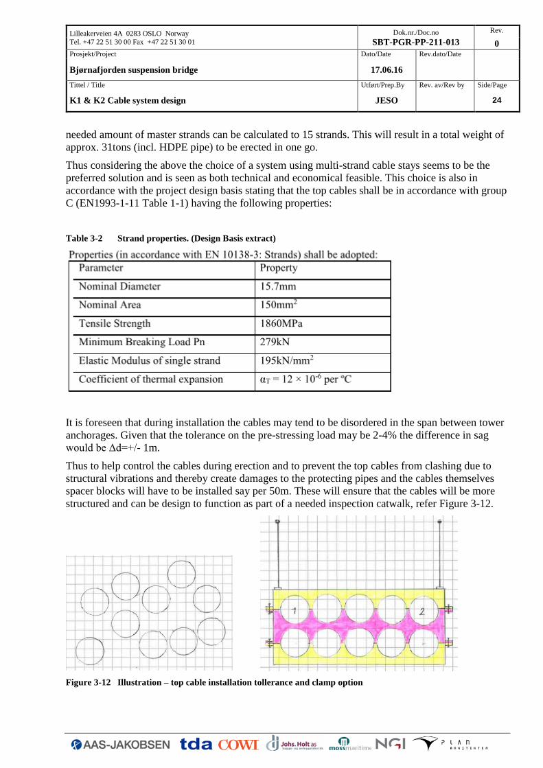
It is foreseen that during installation the cables may tend to be disordered in the span between tower
anchorages. Given that the tolerance on the pre-stressing load may be 2-4% the difference in sag
would be Δd=+/- 1m.
Thus to help control the cables during erection and to prevent the top cables from clashing due to
structural vibrations and thereby create damages to the protecting pipes and the cables themselves
spacer blocks will have to be installed say per 50m. These will ensure that the cables will be more
structured and can be design to function as part of a needed inspection catwalk, refer Figure 3-12.
Figure 3-12 Illustration – top cable installation tollerance and clamp option
Lilleakerveien 4A 0283 OSLO Norway
Tel. +47 22 51 30 00 Fax +47 22 51 30 01
Dok.nr./Doc.no
SBT-PGR-PP-211-013
Rev.
0
Prosjekt/Project Dato/Date Rev.dato/Date
Bjørnafjorden suspension bridge 17.06.16
Tittel / Title Utført/Prep.By Rev. av/Rev by Side/Page
K1 & K2 Cable system design JESO 25
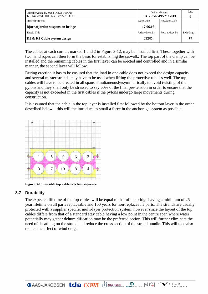
The cables at each corner, marked 1 and 2 in Figure 3-12, may be installed first. These together with
two hand ropes can then form the basis for establishing the catwalk. The top part of the clamp can be
installed and the remaining cables in the first layer can be erected and controlled and in a similar
manner, the second layer will follow.
During erection it has to be ensured that the load in one cable does not exceed the design capacity
and several master strands may have to be used when lifting the protective tube as well. The top
cables will have to be erected in all spans simultaneously/symmetrically to avoid twisting of the
pylons and they shall only be stressed to say 60% of the final pre-tension in order to ensure that the
capacity is not exceeded in the first cables if the pylons undergo large movements during
construction.
It is assumed that the cable in the top layer is installed first followed by the bottom layer in the order
described below – this will the introduce as small a force in the anchorage system as possible.
Figure 3-13 Possible top cable erection sequence
3.7 Durability
The expected lifetime of the top cables will be equal to that of the bridge having a minimum of 25
year lifetime on all parts replaceable and 100 years for non-replaceable parts. The strands are usually
protected with a supplier specific multi-layer protection system, however since the layout of the top
cables differs from that of a standard stay cable having a low point in the centre span where water
potentially may gather dehumidification may be the preferred option. This will further eliminate the
need of sheathing on the strand and reduce the cross section of the strand bundle. This will thus also
reduce the effect of wind drag.
1 6 9 5
4 8 10 7 3
2

Lilleakerveien 4A 0283 OSLO Norway
Tel. +47 22 51 30 00 Fax +47 22 51 30 01
Dok.nr./Doc.no
SBT-PGR-PP-211-013
Rev.
0
Prosjekt/Project Dato/Date Rev.dato/Date
Bjørnafjorden suspension bridge 17.06.16
Tittel / Title Utført/Prep.By Rev. av/Rev by Side/Page
K1 & K2 Cable system design JESO 26
4 HANGERS
4.1 Functionality
The hanger cables support the suspended deck and transfer the load to the suspended cables. The
hangers are typically positioned with a spacing of 24m.
For the shortest hangers at mid span and at the bridge ends large in-plane and out-of-plane rotations
shall be tolerable by providing cylindrical bushings at the upper hanger anchorage point and
spherical bearings at the lower hanger anchorage point. Unacceptable vibration of the longest hanger
cables near the towers shall be mitigated by means of hanger anti-vibration devices.
The structure shall be capable of having a hanger removed at one location at a time for replacement.
Temporary hanger cables shall be used to provide support to the deck during hanger replacement.
Progressive collapse is prevented by considering both a sudden rupture of one hanger cable (e.g.
caused by collision from an errant vehicle), and rupture of two adjacent hangers (e.g. caused by fire).
Hanger rupture have however not been considered at this stage of the design.
4.2 Particulars
The locked coil strand is a commonly used hanger cable option, for which no further arguments need
be made in the design documentation. For example there is no unusual or unknown aspect in regards
to bending stresses. The Hålogaland bridge in Norway has hangers of this type. The selected
component is state-of-the-art in regards to long term durability, and the realistic lifetime may well be
much longer.
For some hangers spherical bearings are required where the angular rotation of the cable relative to
the socket exceeds the normal limits of flexural allowance as provided by the supplier. It is assumed
that the supplier of the hanger cables will deliver the hangers in accordance with the requirements
for rotations specified on the drawings. Thus no further information on bearing type and size is
considered at this project stage.
The torsional stiffness of the suspended cable is very low, thus the suspended cable and cable clamp
rotates as a consequence of deck motion (sway). Therefore only cylindrical bushings are required at
the upper hanger anchorage. These bushings have not been considered in the following.
4.3 Geometry
A hanger comprises N heliacally spun wires and a 3 layers of lock wires assembled in a strand
covered in black polyethylene sheathing with a general geometry as shown in Figure 4-1.

Lilleakerveien 4A 0283 OSLO Norway
Tel. +47 22 51 30 00 Fax +47 22 51 30 01
Dok.nr./Doc.no
SBT-PGR-PP-211-013
Rev.
0
Prosjekt/Project Dato/Date Rev.dato/Date
Bjørnafjorden suspension bridge 17.06.16
Tittel / Title Utført/Prep.By Rev. av/Rev by Side/Page
K1 & K2 Cable system design JESO 27
Figure 4-1 Typical Hanger strand section
The hangers are divided into 2 different sizes with a diameter, steel section area and minimum
breaking load as in the table below.
Hanger dia. Hanger A [mm2] Breaking [MN] dia. pin
Typical 70 3390 4.89 145
At pylon 90 5600 8.09 180
The hanger strand is terminated in each end by a socket, which connects the hanger with the cable
clamp at the top and with the deck at the bottom by a pin having a diameter denoted "dia pin", refer
Figure 4-2.
Figure 4-2 Typical hanger socket
The hangers nearest to the bridge ends and main span centres are furnished with cylindrical bushings
at the upper hanger anchorage (cable clamp) and spherical bearings at the lower hanger anchorage
(deck) to account for hanger rotations.

Lilleakerveien 4A 0283 OSLO Norway
Tel. +47 22 51 30 00 Fax +47 22 51 30 01
Dok.nr./Doc.no
SBT-PGR-PP-211-013
Rev.
0
Prosjekt/Project Dato/Date Rev.dato/Date
Bjørnafjorden suspension bridge 17.06.16
Tittel / Title Utført/Prep.By Rev. av/Rev by Side/Page
K1 & K2 Cable system design JESO 28
4.4 Materials
The following materials are applied:
Locked coiled, LC.
Nominal diameter 7.00mm
Nominal section area 38.5mm2
Minimum tensile strength 1570MPa
Nominal 0.1% proof stress 1550MPa Young’s modulus 2 105 MPa
Sockets of cast steel grade G20Mn5+QT
Pins of bright steel grade 34CrNiMo6 (10277-5) with
Thickness [mm] fy [MPa] fu [MPa]
100 < d ≤ 160 700 900
160 < d ≤ 250 600 800
Structural steel S355N/NL (EN 10025) with
Minimum yield strength
fy [MPa]
Nominal thickness
thk [mm]
355 ≤ 16
4.5 Loads
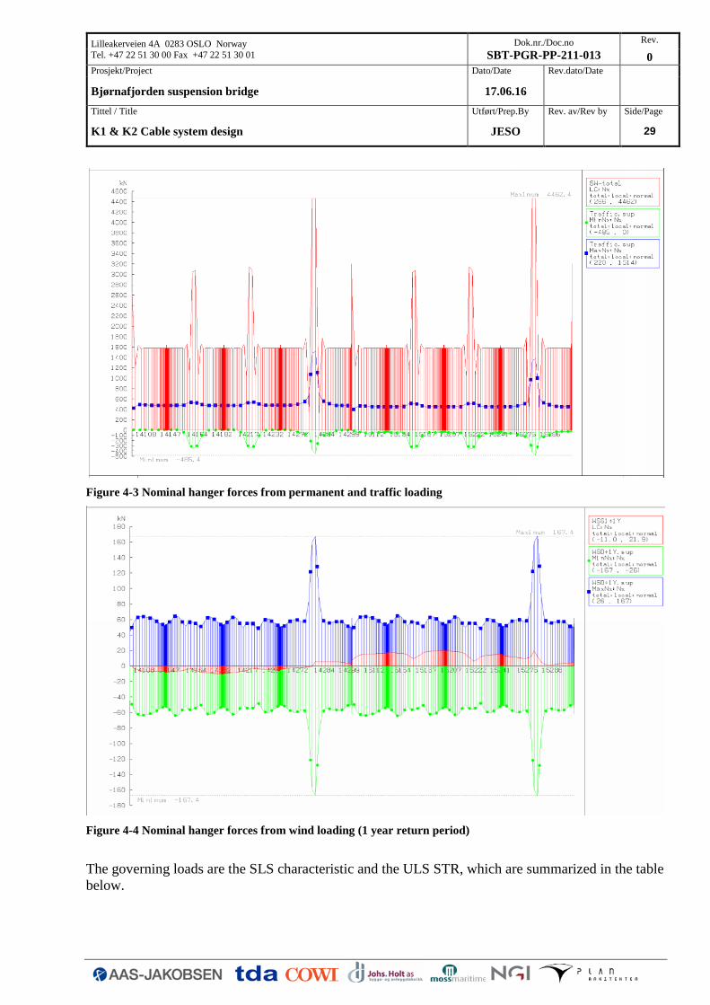
The loads subjected to the hangers are adopted from the global RM Bridge model. The load output is
a set of axial forces from individual load effects such as permanent loads and traffic. From the
calculations it was determined that wind had a negligible effect on the hanger forces, refer Figure
4-4. For the sake of simplicity wind loading has thus been neglected due to its minor contribution.
These load effects are combined in accordance with the provisions in the project specific design
basis resulting in the aggregate design axial force, FEd, which is more or less constant for all hangers
except near pylons and bridge ends. The un-factored load effects are shown in Figure 4-3 below.
Lilleakerveien 4A 0283 OSLO Norway
Tel. +47 22 51 30 00 Fax +47 22 51 30 01
Dok.nr./Doc.no
SBT-PGR-PP-211-013
Rev.
0
Prosjekt/Project Dato/Date Rev.dato/Date
Bjørnafjorden suspension bridge 17.06.16
Tittel / Title Utført/Prep.By Rev. av/Rev by Side/Page
K1 & K2 Cable system design JESO 29
Figure 4-3 Nominal hanger forces from permanent and traffic loading
Figure 4-4 Nominal hanger forces from wind loading (1 year return period)
The governing loads are the SLS characteristic and the ULS STR, which are summarized in the table
below.

Lilleakerveien 4A 0283 OSLO Norway
Tel. +47 22 51 30 00 Fax +47 22 51 30 01
Dok.nr./Doc.no
SBT-PGR-PP-211-013
Rev.
0
Prosjekt/Project Dato/Date Rev.dato/Date
Bjørnafjorden suspension bridge 17.06.16
Tittel / Title Utført/Prep.By Rev. av/Rev by Side/Page
K1 & K2 Cable system design JESO 30
Hanger Typical At Pylon - typ At Pylon - max
FSLS CHAR [MN] 2.10 3.7 5.96
FULS STR [MN] 2.59 4.53 7.38
Loads which cause bending and/or secondary stresses are generally ignored justified by the high
factor of safety used with the axial force.
4.6 Verification
The hanger strand verification includes;
Dimensioning of strand for in-service SLS and ULS
Pin size for typical hanger
Rotations
The verification of the hanger can be found in Appendix C, however key figures are inserted below
for clarity.
4.6.1 Hanger strand
The hanger strand size is primarily designed with respect to the SLS characteristic and the ULS
requirement.
The SLS verification includes a partial material factor of γm = 2.5, and for the ULS the partial
material factor is γm = 1.8,
𝐹𝑢,𝑆𝐿𝑆 =𝐴ℎ𝑎𝑛𝑔𝑒𝑟 ∙ 1570𝑀𝑃𝑎
2.5 , 𝐹𝑢,𝑈𝐿𝑆 =
𝐴ℎ𝑎𝑛𝑔𝑒𝑟 ∙ 1570𝑀𝑃𝑎
1.8
so for a hanger with lock coil LC70 with min. breaking load of 4.89MN it becomes:
SLS: 4.89MN/2.5 = 1.97MN
ULS: 4.89MN/1.8 = 2.72MN
for a hanger with lock coil LC90 with min. breaking load of 8.09MN it becomes:
SLS: 8.09MN/2.5 = 3.23MN
ULS: 8.09MN/1.8 = 4.49MN

Lilleakerveien 4A 0283 OSLO Norway
Tel. +47 22 51 30 00 Fax +47 22 51 30 01
Dok.nr./Doc.no
SBT-PGR-PP-211-013
Rev.
0
Prosjekt/Project Dato/Date Rev.dato/Date
Bjørnafjorden suspension bridge 17.06.16
Tittel / Title Utført/Prep.By Rev. av/Rev by Side/Page
K1 & K2 Cable system design JESO 31
From the above given results it can be seen that for the typical hanger the SLS capacity is slightly
exceeded, however this is deemed acceptable at this stage in the design. In respect to the typical
hanger force at pylons it is found that a hanger type LC90 has sufficient capacity. Special hangers
may be needed at the north tower due to the exceptional high force determined at this location.
4.6.2 Pin
Pin connected members should be arranged such to avoid eccentricity and should be of sufficient
size to distribute the load from the area of the member with the pin hole to the member away from
the pin hole. The design of the pin is the responsibility of the hanger supplier. The following
verification is indicative only. The pinned connection is designed with the following geometry
parameters.
Table 4-1 - Pin, pin hole and socket fork geometry
Hanger no. d d0,clamp d0,deck tclamp tdeck tsocket fork Apin Wel,pin
[-] [mm] [mm] [mm] [mm] [mm] [mm] [m²] [m³]
Typical 145 145 145 90 100 50 0.016 0.00029
d is the diameter of the pin, d0 is the pin hole diameter, t is the thickness of the connected plates, Apin
is the cross sectional area and Wel,pin is the elastic first moment of area of the pin. The pin design is
performed in accordance with EN1993-1-8 clause 3.13.1. The geometrical requirements for pin
ended members comprises,
𝑎 ≥𝐹𝐸𝑑𝛾𝑀0
2𝑡𝑓𝑦+
2𝑑0
3 , 𝑐 ≥
𝐹𝐸𝑑𝛾𝑀0
2𝑡𝑓𝑦+
𝑑0
3
The geometrical demand is ensured fulfilled for the socket, refer Table 4-2, where it can be seen that
the demands are fulfilled assuming that one side takes 60% of the hanger load of 2.6MN.
Table 4-2 - Geometrical requirements for pin connection (Socket)
Provided Demand
Hanger no. FEd t a c a c
[-] [MN] [mm] [mm] [mm] [mm] [mm]
Typical 1.6 50 148 118 146 98

Lilleakerveien 4A 0283 OSLO Norway
Tel. +47 22 51 30 00 Fax +47 22 51 30 01
Dok.nr./Doc.no
SBT-PGR-PP-211-013
Rev.
0
Prosjekt/Project Dato/Date Rev.dato/Date
Bjørnafjorden suspension bridge 17.06.16
Tittel / Title Utført/Prep.By Rev. av/Rev by Side/Page
K1 & K2 Cable system design JESO 32
The design requirements for solid circular pins include a bearing resistance of the connected plate
and the pin, Fb,Rd, shear resistance of the pin, Fv,Rd, bending resistance of the pin MRd,
𝐹𝑏,𝑅𝑑 = 1.5𝑡𝑑𝑓𝑦
𝛾𝑀0≥ 𝐹𝐸𝑑
𝐹𝑣,𝑅𝑑 = 0.6𝐴𝑓𝑢𝑝
𝛾𝑀2≥
𝐹𝐸𝑑
2
𝑀𝑅𝑑 = 1.5𝑊𝑒𝑙𝑓𝑦𝑝
𝛾𝑀0≥ 𝑀𝐸𝑑
and a combined shear and bending resistance
(𝑀𝐸𝑑
𝑀𝑅𝑑)
2
+ (𝐹𝐸𝑑
2 ∙ 𝐹𝑣,𝑅𝑑)
2
≤ 1
The partial factors γM0 = 1.00 and γM2 = 1.25 are applied. fup is the ultimate tensile strength of the
pin, fup = 900MPa for d=145. fy is the lower of the design strengths of the pin and the connected part,
thus calculated as the yield strength of the cable clamp/socket fork, fy = 300MPa. fyp is the yield
strength of the pin, fyp = 700MPa for d=145. The bearing resistance of the socket is calculated for the
fork (2 plates) in order to compare with FEd. The hanger force is shared evenly between the socket
plates, hence the shear force in one section will be FEd /2, refer Figure 4-5 below.
The moments in the pin are calculated assuming that the connected parts form simple supports, and
the reactions between the pin and the connected parts are uniformly distributed along the length in
contact on each part as indicated in Figure 4-5.

Lilleakerveien 4A 0283 OSLO Norway
Tel. +47 22 51 30 00 Fax +47 22 51 30 01
Dok.nr./Doc.no
SBT-PGR-PP-211-013
Rev.
0
Prosjekt/Project Dato/Date Rev.dato/Date
Bjørnafjorden suspension bridge 17.06.16
Tittel / Title Utført/Prep.By Rev. av/Rev by Side/Page
K1 & K2 Cable system design JESO 33
Figure 4-5 - Assumptions concerning bending moments in the pin
The design bending moment in the pin is calculated as,
𝑀𝐸𝑑 =𝐹𝐸𝑑
8(𝑏 + 4𝑐 + 2𝑎)
Where b is the thickness of the eye plate, a is the thickness of the socket plates, a = (wex - win)/2 and
c is the spacing between these plates. For the above calculations uniformity has been assumed
indicating that no relative deformation between suspended cable and deck take place. If the deck
twists or sways the hanger force will be obtained eccentric in the socket plates, however this effect
has been neglected at this stage.
The pin is intended to be replaceable, thus the following requirements applies for bearing and
replaces the above mentioned demands where relevant,
𝐹𝑏,𝑅𝑑,𝑠𝑒𝑟 = 0.6𝑡𝑑𝑓𝑦
𝛾𝑀6≥ 𝐹𝐸𝑑,𝑠𝑒𝑟
for bending
𝑀𝑅𝑑,𝑠𝑒𝑟 = 0.8𝑊𝑒𝑙𝑓𝑦𝑝
𝛾𝑀6≥ 𝑀𝐸𝑑,𝑠𝑒𝑟
all calculated conservatively for ULS loads and summarized in the table below. The result for the
typical hangers is given in Table 4-3 below.

Lilleakerveien 4A 0283 OSLO Norway
Tel. +47 22 51 30 00 Fax +47 22 51 30 01
Dok.nr./Doc.no
SBT-PGR-PP-211-013
Rev.
0
Prosjekt/Project Dato/Date Rev.dato/Date
Bjørnafjorden suspension bridge 17.06.16
Tittel / Title Utført/Prep.By Rev. av/Rev by Side/Page
K1 & K2 Cable system design JESO 34
Table 4-3 Pin verification results
If there is a risk of pins becoming loose, they should be secured. This can done by means of spacer
rings inside the socket, and end plates outside the socket.
4.7 Hanger rotations
4.7.1 Service loads
The RM Bridge model does not include bearings, but master-slave connections have been assigned
at specific hanger locations to determine the relative motion, between the suspended cable and the
suspended deck, which result in a hanger rotation. The axial and radial rotations can thus be
determined.
Axial rotations means bearing in-plane rotations along bridge (longitudinal rotations), whereas radial
rotations means out-of-plane rotations (transverse to bridge axis). In the following only the radial
rotations have been considered, since these are normally governing.
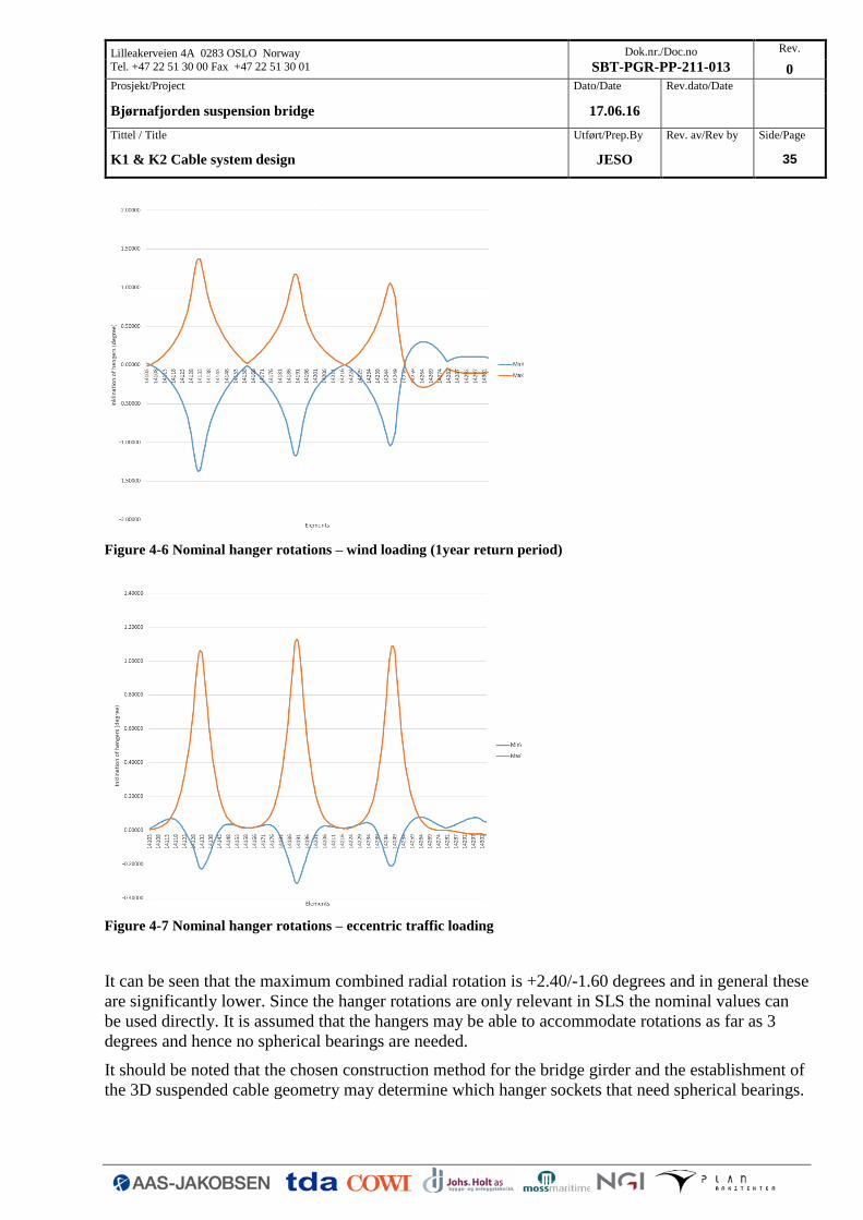
The hanger at mid span has been examined for in-service effects due to lateral wind and eccentric
located traffic loads which is expected to be the governing load situation. In the following figures
the recorded in-service rotations can be seen for each load effect (un-factored values):
Lilleakerveien 4A 0283 OSLO Norway
Tel. +47 22 51 30 00 Fax +47 22 51 30 01
Dok.nr./Doc.no
SBT-PGR-PP-211-013
Rev.
0
Prosjekt/Project Dato/Date Rev.dato/Date
Bjørnafjorden suspension bridge 17.06.16
Tittel / Title Utført/Prep.By Rev. av/Rev by Side/Page
K1 & K2 Cable system design JESO 35
Figure 4-6 Nominal hanger rotations – wind loading (1year return period)
Figure 4-7 Nominal hanger rotations – eccentric traffic loading
It can be seen that the maximum combined radial rotation is +2.40/-1.60 degrees and in general these
are significantly lower. Since the hanger rotations are only relevant in SLS the nominal values can
be used directly. It is assumed that the hangers may be able to accommodate rotations as far as 3
degrees and hence no spherical bearings are needed.
It should be noted that the chosen construction method for the bridge girder and the establishment of
the 3D suspended cable geometry may determine which hanger sockets that need spherical bearings.

Lilleakerveien 4A 0283 OSLO Norway
Tel. +47 22 51 30 00 Fax +47 22 51 30 01
Dok.nr./Doc.no
SBT-PGR-PP-211-013
Rev.
0
Prosjekt/Project Dato/Date Rev.dato/Date
Bjørnafjorden suspension bridge 17.06.16
Tittel / Title Utført/Prep.By Rev. av/Rev by Side/Page
K1 & K2 Cable system design JESO 36
Since the method has not yet been established this has not been investigated further at this stage of
the design.
Lilleakerveien 4A 0283 OSLO Norway
Tel. +47 22 51 30 00 Fax +47 22 51 30 01
Dok.nr./Doc.no
SBT-PGR-PP-211-013
Rev.
0
Prosjekt/Project Dato/Date Rev.dato/Date
Bjørnafjorden suspension bridge 17.06.16
Tittel / Title Utført/Prep.By Rev. av/Rev by Side/Page
K1 & K2 Cable system design JESO 37
5 CABLE CLAMPS
5.1 Geometry
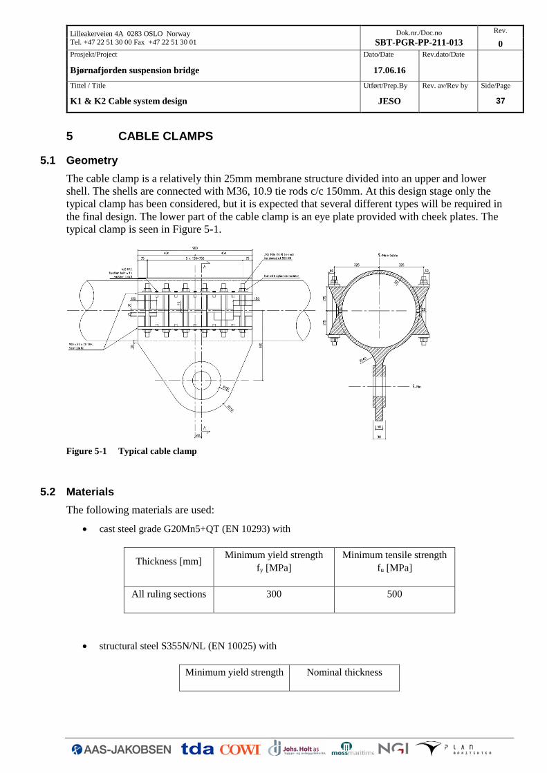
The cable clamp is a relatively thin 25mm membrane structure divided into an upper and lower
shell. The shells are connected with M36, 10.9 tie rods c/c 150mm. At this design stage only the
typical clamp has been considered, but it is expected that several different types will be required in
the final design. The lower part of the cable clamp is an eye plate provided with cheek plates. The
typical clamp is seen in Figure 5-1.
Figure 5-1 Typical cable clamp
5.2 Materials
The following materials are used:
cast steel grade G20Mn5+QT (EN 10293) with
Thickness [mm] Minimum yield strength
fy [MPa]
Minimum tensile strength
fu [MPa]
All ruling sections 300 500
structural steel S355N/NL (EN 10025) with
Minimum yield strength Nominal thickness

Lilleakerveien 4A 0283 OSLO Norway
Tel. +47 22 51 30 00 Fax +47 22 51 30 01
Dok.nr./Doc.no
SBT-PGR-PP-211-013
Rev.
0
Prosjekt/Project Dato/Date Rev.dato/Date
Bjørnafjorden suspension bridge 17.06.16
Tittel / Title Utført/Prep.By Rev. av/Rev by Side/Page
K1 & K2 Cable system design JESO 38
fy [MPa] thk [mm]
355 ≤ 16
345 16 < thk ≤ 40
335 40 < thk ≤ 63
tie rods class 10.9 (EN 14399) with
f0.2 [MPa] fu [MPa]
900 1000
nuts and washers class 10.9 (EN 14399) with σp = 1040MPa
5.3 Loads
The cable clamps are subjected to loads adopted from the global RM Bridge model similar to the
hanger forces, refer section 4.5. Since only the typical clamp is considered the forces for the
verification is determined to:
Clamp Typical
FSLS CHAR [MN] 2.10
FULS STR [MN] 2.59
5.4 Verification
The verification of the cable clamp comprises the following:
Anti-slip capacity (shear keys), EN 1993-1-11 cl. 6.4.1
Tie rods, EN1993-1-8
Eye plates, EN1993-1-8 cl. 3.13.1
The verification of the cable clamp can be found in Appendix D. The basis geometrical demands are
repeated in the following.

Lilleakerveien 4A 0283 OSLO Norway
Tel. +47 22 51 30 00 Fax +47 22 51 30 01
Dok.nr./Doc.no
SBT-PGR-PP-211-013
Rev.
0
Prosjekt/Project Dato/Date Rev.dato/Date
Bjørnafjorden suspension bridge 17.06.16
Tittel / Title Utført/Prep.By Rev. av/Rev by Side/Page
K1 & K2 Cable system design JESO 39
The eye plate of the cable clamp is subjected to the hanger force through the pinned connection
between the hanger socket and the cable clamp. The eye plate is reinforced by cheek plates to reduce
the stress in the contact zone, refer Figure 5-1.
The eye plate dimensions shall comply with
𝑎 ≥𝐹𝐸𝑑𝛾𝑀0
2𝑡𝑓𝑦+
2𝑑0
3 , 𝑐 ≥
𝐹𝐸𝑑𝛾𝑀0
2𝑡𝑓𝑦+
𝑑0
3
The following geometrical dimensions has been used for the cable clamp, refer Table 5-1.
Table 5-1 - Geometrical requirements for pin connection (Clamp)
Provided Demand
Hanger no. FEd t a c a c
[-] [MN] [mm] [mm] [mm] [mm] [mm]
Typical 2.59 50 178 270 180 131
It can be seen that the demand to “a” is not fulfilled, however since the local thickness of the clamp
is 90mm due to attached cheek plates it is found acceptable.
Lilleakerveien 4A 0283 OSLO Norway
Tel. +47 22 51 30 00 Fax +47 22 51 30 01
Dok.nr./Doc.no
SBT-PGR-PP-211-013
Rev.
0
Prosjekt/Project Dato/Date Rev.dato/Date
Bjørnafjorden suspension bridge 17.06.16
Tittel / Title Utført/Prep.By Rev. av/Rev by Side/Page
K1 & K2 Cable system design JESO 40
6 PYLON SADDLES
6.1 Introduction
The tower saddle verifications are typically based on maximum suspended cable forces calculated
by the global RM Bridge model.
The saddle shall support the suspended cable on the tower top in such a way that the side pressures
to wires are acceptably small and so that each wire has a smooth alignment across the saddle. The
radius of the saddle trough is determined due to the limitation in regards to side pressure to the wire.
The saddle fulfils the purpose of distributing the huge suspended cable load onto the tower plates as
uniformly as can be. Two different designs of the pylon saddles is necessary since the floating
pylons at axis 5 & 6 are constructed in steel, whereas the fixed pylons are constructed in concrete.
Moreover the top cable anchorage is a separate structure for the steel pylons, but integrated in the
saddles on the concrete pylons. As the suspended cable has more strands in the side span than in the
main span, these extra strands also needs to be anchored at the saddle giving a different
configuration to those in axis 5 & 6.
6.2 Geometry
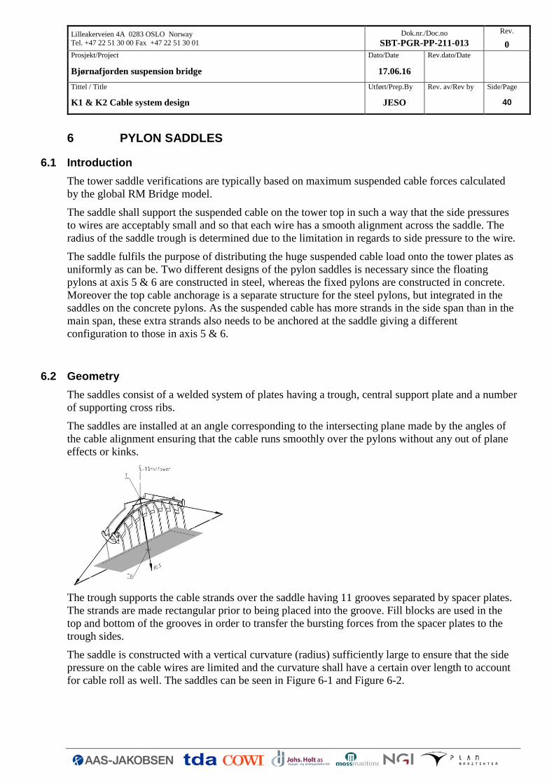
The saddles consist of a welded system of plates having a trough, central support plate and a number
of supporting cross ribs.
The saddles are installed at an angle corresponding to the intersecting plane made by the angles of
the cable alignment ensuring that the cable runs smoothly over the pylons without any out of plane
effects or kinks.
The trough supports the cable strands over the saddle having 11 grooves separated by spacer plates.
The strands are made rectangular prior to being placed into the groove. Fill blocks are used in the
top and bottom of the grooves in order to transfer the bursting forces from the spacer plates to the
trough sides.
The saddle is constructed with a vertical curvature (radius) sufficiently large to ensure that the side
pressure on the cable wires are limited and the curvature shall have a certain over length to account
for cable roll as well. The saddles can be seen in Figure 6-1 and Figure 6-2.

Lilleakerveien 4A 0283 OSLO Norway
Tel. +47 22 51 30 00 Fax +47 22 51 30 01
Dok.nr./Doc.no
SBT-PGR-PP-211-013
Rev.
0
Prosjekt/Project Dato/Date Rev.dato/Date
Bjørnafjorden suspension bridge 17.06.16
Tittel / Title Utført/Prep.By Rev. av/Rev by Side/Page
K1 & K2 Cable system design JESO 41
Figure 6-1 Saddle at steel pylons – axis 5 & 6
Figure 6-2 Saddle at concrete pylons – axis 4 & 7
The saddle trough sides are designed for the persistent side pressures in ultimate limit state, which
are equal to 1/3 of the radial pressure on the trough bottom plate reducing linearly to 0 at the top of
the side plate.
There is no structural cross tie in the top of the saddles which is also the case for most suspension
bridge saddles. All saddles are considered to be supplied with lids, but they are non-structural.
Structural ties above cable would prevent inspection, cannot be removed after installation and is
considered being a less optimal design.
The saddle trough is considered to be dehumidified.
6.2.1 Materials
The following materials are applied:
steel grade S460M/ML (EN 10025) with

Lilleakerveien 4A 0283 OSLO Norway
Tel. +47 22 51 30 00 Fax +47 22 51 30 01
Dok.nr./Doc.no
SBT-PGR-PP-211-013
Rev.
0
Prosjekt/Project Dato/Date Rev.dato/Date
Bjørnafjorden suspension bridge 17.06.16
Tittel / Title Utført/Prep.By Rev. av/Rev by Side/Page
K1 & K2 Cable system design JESO 42
fy [MPa] thk [mm]
460 ≤ 16
440 16 < thk ≤ 40
430 40 < thk ≤ 63
410 63 < thk ≤ 80
400 80 < thk ≤ 100
380 100 < thk ≤ 150
370 150 < thk ≤ 200
bolts class 10.9 (EN 14399)
6.3 Verification
In the following only the saddles overall structure on the steel pylons in axis 5 & 6 has been
considered. However the top cable anchorage and the anchorage structure for additional strands in
axis 4 & 7 has also been considered. The verification is given in Appendix E and only main
principles are repeated here. In respect to pressure on the suspended cable wires and selection of
trough radius reference is also made to section 2.2.4.
6.3.1 Pressure distribution
The calculation is based on a ULS load in the suspended cable of 220MN. It is after final updates of
the RM Bridge model found a suspended cable force of 218MN. Due to this minor change in force
the calculations have not been updated.
The total load from the suspended cable can be expressed by distributed pressures to saddle trough
bottom and sides. The suspended cable force of 220MN corresponding to a tensile force in each of
the 87 strands of Ps=2.53MN per strand. The pressure on the bottom plate will be largest under the
central groove having 11 stacks of strands. The bottom plate is curved with R=5.2m giving a force
per linear metre of:
P = 11 x 2.53 / 5.2 = 5.35 MN/m or
pV = 5.35 / (5.15mm x 11+10mm)/1000 = 80.3 MPa

Lilleakerveien 4A 0283 OSLO Norway
Tel. +47 22 51 30 00 Fax +47 22 51 30 01
Dok.nr./Doc.no
SBT-PGR-PP-211-013
Rev.
0
Prosjekt/Project Dato/Date Rev.dato/Date
Bjørnafjorden suspension bridge 17.06.16
Tittel / Title Utført/Prep.By Rev. av/Rev by Side/Page
K1 & K2 Cable system design JESO 43
In regards to horizontal pressure to the trough sides, the average stack height of 8.2 strands are used.
The lateral pressure is taken as 1/3 as the corresponding vertical pressure at the same level, leading
to a maximum pressure of
› pH = 19.9 MPa
linearly varying to 0 at the top of the 8.2 strands.
6.3.2 Wires
The linear load per metre of the central stack of strands have been calculated to P=5.35MN/m. This
load shall be shared by 11 wires, leading to a transverse load to each wire of
P = 5.35/ 11 = 0.49 MN/m < 0.65 MN/m, satisfactory.
6.3.3 Trough bottom
The pressure to the trough bottom plate is considered carried by transverse bending and longitudinal
bending considering the trough sides and central plate as fixed supports. Thus a configuration of a
plate field in accordance with EN1993-1-7 B.3.2 has been considered. Assuming for simplicity that
the pressure is evenly distributed over the bottom plate having q=3pH = 60MPa the stresses in the
plate longitudinal and transverse direction can be calculated along with the stresses at the boundaries
as follows:

Lilleakerveien 4A 0283 OSLO Norway
Tel. +47 22 51 30 00 Fax +47 22 51 30 01
Dok.nr./Doc.no
SBT-PGR-PP-211-013
Rev.
0
Prosjekt/Project Dato/Date Rev.dato/Date
Bjørnafjorden suspension bridge 17.06.16
Tittel / Title Utført/Prep.By Rev. av/Rev by Side/Page
K1 & K2 Cable system design JESO 44
𝜎𝑥 =0.197 ∙ 59.7𝑀𝑁/𝑚2 ∙ (0.364𝑚)2
(0.12𝑚)2= 108𝑀𝑃𝑎
𝜎𝑦 =0.125 ∙ 59.7𝑀𝑁/𝑚2 ∙ (0.364𝑚)2
(0.12𝑚)2= 68𝑀𝑃𝑎
𝜎𝑥,𝑏 =−0.49 ∙ 59.7𝑀𝑁/𝑚2 ∙ (0.364𝑚)2
(0.12𝑚)2= −268𝑀𝑃𝑎
Due to the small thickness to width ratio of the plate no account for buckling is made. It can be seen
that the stresses are highest at the boundaries but still below the allowable limit of fyd=350MPa.
6.3.4 Trough sides
The trough sides can be calculated much the same way as the bottom plate, however, for simplicity
only bearing in the longitudinal direction is assumed. To simplify the verification an average
pressure of 2/3pH=13.3MPa is used between the cross ribs which is located every 0.5m.

Lilleakerveien 4A 0283 OSLO Norway
Tel. +47 22 51 30 00 Fax +47 22 51 30 01
Dok.nr./Doc.no
SBT-PGR-PP-211-013
Rev.
0
Prosjekt/Project Dato/Date Rev.dato/Date
Bjørnafjorden suspension bridge 17.06.16
Tittel / Title Utført/Prep.By Rev. av/Rev by Side/Page
K1 & K2 Cable system design JESO 45
The flexural stresses in wall section are determined to:
𝑀𝐷 =1
12∙ 13.3𝑀𝑃𝑎 ∙ (0.50𝑚)2 = 0.28𝑀𝑁𝑚/𝑚
𝜎𝐶 =0.84𝑀𝑁𝑚/𝑚
16 ∙ (0.07𝑚)2
= 338𝑀𝑃𝑎 < 390𝑀𝑃𝑎
6.3.5 Support ribs
The transverse plates (support ribs) which support the trough from the bottom and on both sides, are
subjected to direct vertical forces under the trough bottom plate, the transverse cable spread forces,
and also some vertical load from the suspended cable which is carried by the outer edges of the
bottom plate and, in turn, the trough side plates. The forces are derived in compliance with the load
distribution assumed for trough bottom and sides, however the direct effect vertically on the trough
side is neglected and considered conservative.
The bending moment can be calculated by determining the reaction R assuming uniform loading as
illustrated in section 6.3.3:

Lilleakerveien 4A 0283 OSLO Norway
Tel. +47 22 51 30 00 Fax +47 22 51 30 01
Dok.nr./Doc.no
SBT-PGR-PP-211-013
Rev.
0
Prosjekt/Project Dato/Date Rev.dato/Date
Bjørnafjorden suspension bridge 17.06.16
Tittel / Title Utført/Prep.By Rev. av/Rev by Side/Page
K1 & K2 Cable system design JESO 46
𝑅 =1
2∙ 13.3𝑀𝑃𝑎 ∙ 0.5𝑚 = 3.31𝑀𝑁/𝑚
𝑀 =1
2∙ 3.31𝑀𝑁/𝑚 ∙ (0.45𝑚)2 = 0.335𝑀𝑁𝑚
𝜎𝐶 =0.335𝑀𝑁𝑚
16 ∙ 0.06𝑚 ∙ (0.3𝑚)2
= 380𝑀𝑃𝑎 < 390𝑀𝑃𝑎
The actual height in section 1 is close to 0.35m limiting the stress to 280MPa, meaning that steel
S355 could be used for the cross rib in principal.
6.3.6 Central plate
The 60mm thick longitudinal plates under the trough bottom are subjected to direct vertical pressure
in compliance with the assumptions above.
Having the avarage pressure of 59.7MPa distributed over a bottom plate area of WxL=0.73mx0.5m
equals a force of F=21.8MN. This force will give compression in both the central plate and the cross
rib, so the total compressive area and stress can then be calculated to:
𝐴 = 0.5𝑚 ∙ 0.06𝑚 + 0.73𝑚 ∙ 0.06𝑚 = 0.074𝑚2
𝑄 =𝐹
𝐴= 296𝑀𝑃𝑎
The 60mm central plate is thus satisfactory.

Lilleakerveien 4A 0283 OSLO Norway
Tel. +47 22 51 30 00 Fax +47 22 51 30 01
Dok.nr./Doc.no
SBT-PGR-PP-211-013
Rev.
0
Prosjekt/Project Dato/Date Rev.dato/Date
Bjørnafjorden suspension bridge 17.06.16
Tittel / Title Utført/Prep.By Rev. av/Rev by Side/Page
K1 & K2 Cable system design JESO 47
7 SPLAY SADDLES
7.1 Introduction
This chapter describes the verification of the splay saddles. Only the south splay saddle has been
considered and it is assumed similar for the north anchorage. The splay saddle verifications are
typically based on maximum suspended cable forces calculated by the global RM Bridge model.
The splay saddle deviates the strands of the suspended cable vertically and horizontally in order to
separate the strands for fixing to the anchorage massif. Each strand continues to a different point on
the anchor massif sufficiently spaced to provide access for installation of the cross head slabs and
anchorage tendons in the concrete behind.
7.2 Geometry
The saddle is constructed in a similar manner to the pylon saddles consisting of a trough, central
support plate and cross ribs, but with the addition of a shoulder plate along the side of the trough to
support the additional side pressure from the horizontal spread of the strands.
The saddle trough has 11 grooves separated by spacer plates. The strands are made rectangular prior
to being placed into the groove.
The correct curvature is obtained by detailed and precise spacer plates and by applying fill material
to the trough sides and bottom obtaining the expected geometry.
Similar with the other saddles the arrangement has to be in such a way that the side pressures to
wires are acceptably small and so that each wire has a smooth alignment across the saddle. The
radius of the saddle trough is determined by the limitation in regards to side pressure.
As the bundle of wires will tend to burst when supported from below, the saddle trough sides shall
be designed to resist this bursting force. The horizontal splay will further add a pressure which the
trough sides shall be designed to resist.
The saddle plates transfers the radial cable force to the rocker bearing, which rotates to permit the
extension of the strands in the splay chamber due to their change in stress and temperature during
construction and operation.
The alignment of each strand in the saddle and their top and bottom setting-out point should be
specified to complete detail. For each strand the arrival point and the departure point can be
geometrically determined, and the vertical and horizontal curvature of the saddle trough can be
checked so that the strand alignment is as theoretically desired. This geometrical exercise has
however not been performed at this stage of the design and should be further developed in a detailed
phase.
7.2.1 Material
The material used for the saddle is S460M/S460ML structural steel with the following properties.
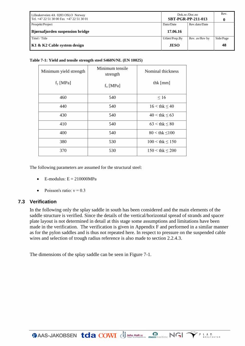
Lilleakerveien 4A 0283 OSLO Norway
Tel. +47 22 51 30 00 Fax +47 22 51 30 01
Dok.nr./Doc.no
SBT-PGR-PP-211-013
Rev.
0
Prosjekt/Project Dato/Date Rev.dato/Date
Bjørnafjorden suspension bridge 17.06.16
Tittel / Title Utført/Prep.By Rev. av/Rev by Side/Page
K1 & K2 Cable system design JESO 48
Table 7-1: Yield and tensile strength steel S460N/NL (EN 10025)
Minimum yield strength
fy [MPa]
Minimum tensile
strength
fu [MPa]
Nominal thickness
thk [mm]
460 540 ≤ 16
440 540 16 < thk ≤ 40
430 540 40 < thk ≤ 63
410 540 63 < thk ≤ 80
400 540 80 < thk ≤100
380 530 100 < thk ≤ 150
370 530 150 < thk ≤ 200
The following parameters are assumed for the structural steel:
E-modulus: E = 210000MPa
Poisson's ratio: ν = 0.3
7.3 Verification
In the following only the splay saddle in south has been considered and the main elements of the
saddle structure is verified. Since the details of the vertical/horizontal spread of strands and spacer
plate layout is not determined in detail at this stage some assumptions and limitations have been
made in the verification. The verification is given in Appendix F and performed in a similar manner
as for the pylon saddles and is thus not repeated here. In respect to pressure on the suspended cable
wires and selection of trough radius reference is also made to section 2.2.4.3.
The dimensions of the splay saddle can be seen in Figure 7-1.

Lilleakerveien 4A 0283 OSLO Norway
Tel. +47 22 51 30 00 Fax +47 22 51 30 01
Dok.nr./Doc.no
SBT-PGR-PP-211-013
Rev.
0
Prosjekt/Project Dato/Date Rev.dato/Date
Bjørnafjorden suspension bridge 17.06.16
Tittel / Title Utført/Prep.By Rev. av/Rev by Side/Page
K1 & K2 Cable system design JESO 49
Figure 7-1 Splay saddle

Lilleakerveien 4A 0283 OSLO Norway
Tel. +47 22 51 30 00 Fax +47 22 51 30 01
Dok.nr./Doc.no
SBT-PGR-PP-211-013
Rev.
0
Prosjekt/Project Dato/Date Rev.dato/Date
Bjørnafjorden suspension bridge 17.06.16
Tittel / Title Utført/Prep.By Rev. av/Rev by Side/Page
K1 & K2 Cable system design JESO A.1
A. TOP CABLE ANCHORAGE – VERIFICATION In the following a verification of the top cable anchorage system can be seen. The anchor plate itself
is not verified at this project stage.
The top cables and top cable anchorage have been verified for a maximum load of 80MN and a delta
load between cables in two spans of 40MN. The top cable axial force have due to late changes to the
global model been increased to 112MN. This load will give a slight overutilization of the anchorage
structure, which however is considered to be proven sufficient using FE. No update of the anchorage
structure has thus been included at this stage.

Lilleakerveien 4A 0283 OSLO Norway
Tel. +47 22 51 30 00 Fax +47 22 51 30 01
Dok.nr./Doc.no
SBT-PGR-PP-211-013
Rev.
0
Prosjekt/Project Dato/Date Rev.dato/Date
Bjørnafjorden suspension bridge 17.06.16
Tittel / Title Utført/Prep.By Rev. av/Rev by Side/Page
K1 & K2 Cable system design JESO A.2

Lilleakerveien 4A 0283 OSLO Norway
Tel. +47 22 51 30 00 Fax +47 22 51 30 01
Dok.nr./Doc.no
SBT-PGR-PP-211-013
Rev.
0
Prosjekt/Project Dato/Date Rev.dato/Date
Bjørnafjorden suspension bridge 17.06.16
Tittel / Title Utført/Prep.By Rev. av/Rev by Side/Page
K1 & K2 Cable system design JESO A.3
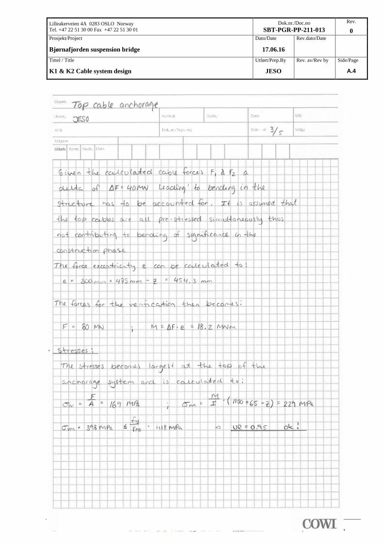
Lilleakerveien 4A 0283 OSLO Norway
Tel. +47 22 51 30 00 Fax +47 22 51 30 01
Dok.nr./Doc.no
SBT-PGR-PP-211-013
Rev.
0
Prosjekt/Project Dato/Date Rev.dato/Date
Bjørnafjorden suspension bridge 17.06.16
Tittel / Title Utført/Prep.By Rev. av/Rev by Side/Page
K1 & K2 Cable system design JESO A.4
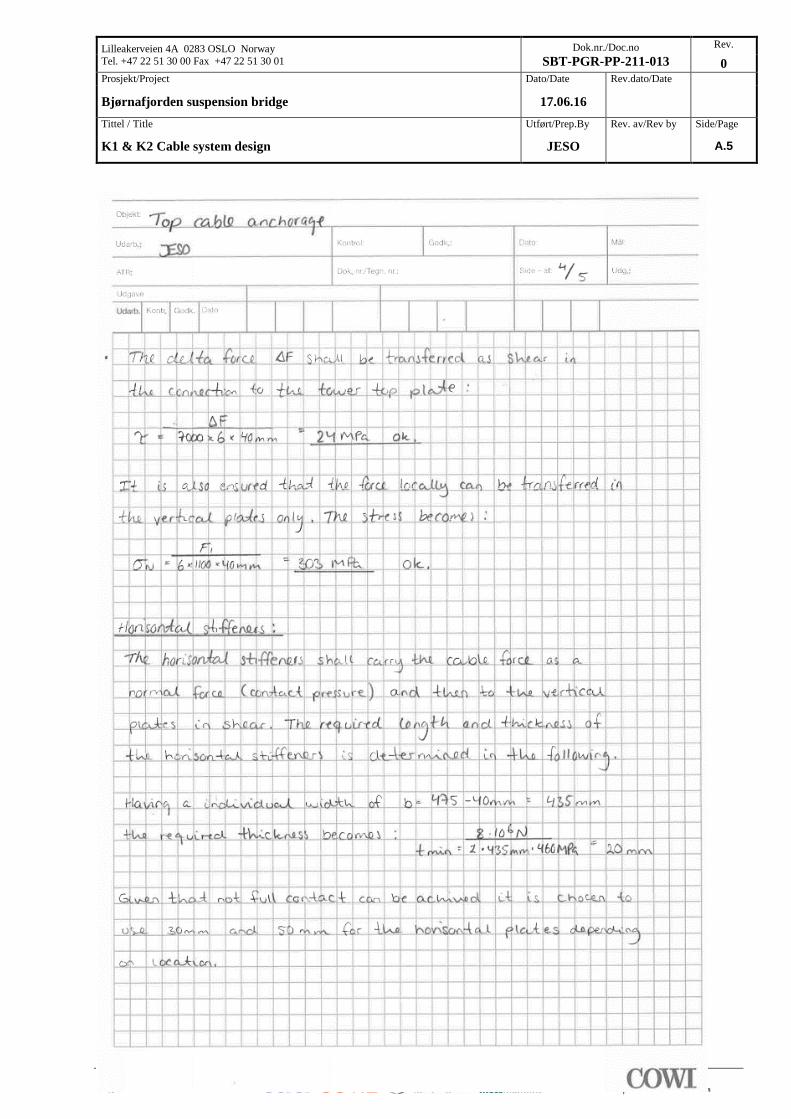
Lilleakerveien 4A 0283 OSLO Norway
Tel. +47 22 51 30 00 Fax +47 22 51 30 01
Dok.nr./Doc.no
SBT-PGR-PP-211-013
Rev.
0
Prosjekt/Project Dato/Date Rev.dato/Date
Bjørnafjorden suspension bridge 17.06.16
Tittel / Title Utført/Prep.By Rev. av/Rev by Side/Page
K1 & K2 Cable system design JESO A.5

Lilleakerveien 4A 0283 OSLO Norway
Tel. +47 22 51 30 00 Fax +47 22 51 30 01
Dok.nr./Doc.no
SBT-PGR-PP-211-013
Rev.
0
Prosjekt/Project Dato/Date Rev.dato/Date
Bjørnafjorden suspension bridge 17.06.16
Tittel / Title Utført/Prep.By Rev. av/Rev by Side/Page
K1 & K2 Cable system design JESO A.6

Lilleakerveien 4A 0283 OSLO Norway
Tel. +47 22 51 30 00 Fax +47 22 51 30 01
Dok.nr./Doc.no
SBT-PGR-PP-211-013
Rev.
0
Prosjekt/Project Dato/Date Rev.dato/Date
Bjørnafjorden suspension bridge 17.06.16
Tittel / Title Utført/Prep.By Rev. av/Rev by Side/Page
K1 & K2 Cable system design JESO B.1
B. SADDLE ANCHORAGE – VERIFICATION In the following the additional strand anchorages on the tower saddles towards side span is
considered. The calculation is based on a strand load of 2.5MN, however late updates of the RM
Bridge model has lead to a strand load of 2.69MN, refer section 2.2. The calculation has not been
updated based on this change. Given the conservatism in the calculation approach is is estimated that
a FE model will still show sufficient capacity of the structure. The structural solution is thus still
found feasible.

Lilleakerveien 4A 0283 OSLO Norway
Tel. +47 22 51 30 00 Fax +47 22 51 30 01
Dok.nr./Doc.no
SBT-PGR-PP-211-013
Rev.
0
Prosjekt/Project Dato/Date Rev.dato/Date
Bjørnafjorden suspension bridge 17.06.16
Tittel / Title Utført/Prep.By Rev. av/Rev by Side/Page
K1 & K2 Cable system design JESO B.2

Lilleakerveien 4A 0283 OSLO Norway
Tel. +47 22 51 30 00 Fax +47 22 51 30 01
Dok.nr./Doc.no
SBT-PGR-PP-211-013
Rev.
0
Prosjekt/Project Dato/Date Rev.dato/Date
Bjørnafjorden suspension bridge 17.06.16
Tittel / Title Utført/Prep.By Rev. av/Rev by Side/Page
K1 & K2 Cable system design JESO B.3

Lilleakerveien 4A 0283 OSLO Norway
Tel. +47 22 51 30 00 Fax +47 22 51 30 01
Dok.nr./Doc.no
SBT-PGR-PP-211-013
Rev.
0
Prosjekt/Project Dato/Date Rev.dato/Date
Bjørnafjorden suspension bridge 17.06.16
Tittel / Title Utført/Prep.By Rev. av/Rev by Side/Page
K1 & K2 Cable system design JESO B.4

Lilleakerveien 4A 0283 OSLO Norway
Tel. +47 22 51 30 00 Fax +47 22 51 30 01
Dok.nr./Doc.no
SBT-PGR-PP-211-013
Rev.
0
Prosjekt/Project Dato/Date Rev.dato/Date
Bjørnafjorden suspension bridge 17.06.16
Tittel / Title Utført/Prep.By Rev. av/Rev by Side/Page
K1 & K2 Cable system design JESO C.1
C. HANGER In the following the capacity of the hangers are verified. It should be noted that the verification is
performed for slightly different loads than reported in section 4.6, which is due to a late update of
the FE model. The calculation has not been updated, and as shown in the main report sufficient
capacity is still obtained.

Lilleakerveien 4A 0283 OSLO Norway
Tel. +47 22 51 30 00 Fax +47 22 51 30 01
Dok.nr./Doc.no
SBT-PGR-PP-211-013
Rev.
0
Prosjekt/Project Dato/Date Rev.dato/Date
Bjørnafjorden suspension bridge 17.06.16
Tittel / Title Utført/Prep.By Rev. av/Rev by Side/Page
K1 & K2 Cable system design JESO C.2

Lilleakerveien 4A 0283 OSLO Norway
Tel. +47 22 51 30 00 Fax +47 22 51 30 01
Dok.nr./Doc.no
SBT-PGR-PP-211-013
Rev.
0
Prosjekt/Project Dato/Date Rev.dato/Date
Bjørnafjorden suspension bridge 17.06.16
Tittel / Title Utført/Prep.By Rev. av/Rev by Side/Page
K1 & K2 Cable system design JESO C.3
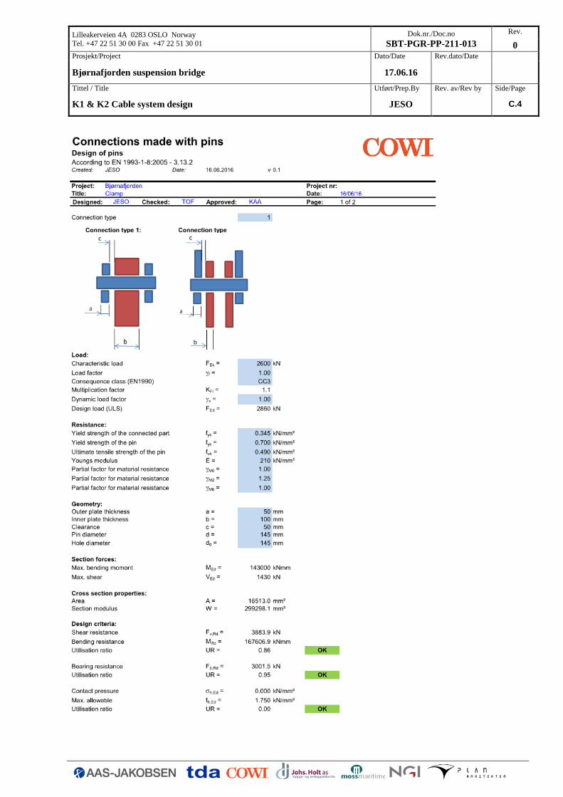
Lilleakerveien 4A 0283 OSLO Norway
Tel. +47 22 51 30 00 Fax +47 22 51 30 01
Dok.nr./Doc.no
SBT-PGR-PP-211-013
Rev.
0
Prosjekt/Project Dato/Date Rev.dato/Date
Bjørnafjorden suspension bridge 17.06.16
Tittel / Title Utført/Prep.By Rev. av/Rev by Side/Page
K1 & K2 Cable system design JESO C.4

Lilleakerveien 4A 0283 OSLO Norway
Tel. +47 22 51 30 00 Fax +47 22 51 30 01
Dok.nr./Doc.no
SBT-PGR-PP-211-013
Rev.
0
Prosjekt/Project Dato/Date Rev.dato/Date
Bjørnafjorden suspension bridge 17.06.16
Tittel / Title Utført/Prep.By Rev. av/Rev by Side/Page
K1 & K2 Cable system design JESO D.1
D. CLAMP In the following the capacity of the typical cable clamp is verified. It should be noted that the
verification is performed for slightly different loads than reported in section 4.6, which is due to a
late update of the FE model. The calculation has not been updated, and as shown in the main report
sufficient capacity is still obtained.

Lilleakerveien 4A 0283 OSLO Norway
Tel. +47 22 51 30 00 Fax +47 22 51 30 01
Dok.nr./Doc.no
SBT-PGR-PP-211-013
Rev.
0
Prosjekt/Project Dato/Date Rev.dato/Date
Bjørnafjorden suspension bridge 17.06.16
Tittel / Title Utført/Prep.By Rev. av/Rev by Side/Page
K1 & K2 Cable system design JESO D.2

Lilleakerveien 4A 0283 OSLO Norway
Tel. +47 22 51 30 00 Fax +47 22 51 30 01
Dok.nr./Doc.no
SBT-PGR-PP-211-013
Rev.
0
Prosjekt/Project Dato/Date Rev.dato/Date
Bjørnafjorden suspension bridge 17.06.16
Tittel / Title Utført/Prep.By Rev. av/Rev by Side/Page
K1 & K2 Cable system design JESO D.3

Lilleakerveien 4A 0283 OSLO Norway
Tel. +47 22 51 30 00 Fax +47 22 51 30 01
Dok.nr./Doc.no
SBT-PGR-PP-211-013
Rev.
0
Prosjekt/Project Dato/Date Rev.dato/Date
Bjørnafjorden suspension bridge 17.06.16
Tittel / Title Utført/Prep.By Rev. av/Rev by Side/Page
K1 & K2 Cable system design JESO D.4

Lilleakerveien 4A 0283 OSLO Norway
Tel. +47 22 51 30 00 Fax +47 22 51 30 01
Dok.nr./Doc.no
SBT-PGR-PP-211-013
Rev.
0
Prosjekt/Project Dato/Date Rev.dato/Date
Bjørnafjorden suspension bridge 17.06.16
Tittel / Title Utført/Prep.By Rev. av/Rev by Side/Page
K1 & K2 Cable system design JESO D.5

Lilleakerveien 4A 0283 OSLO Norway
Tel. +47 22 51 30 00 Fax +47 22 51 30 01
Dok.nr./Doc.no
SBT-PGR-PP-211-013
Rev.
0
Prosjekt/Project Dato/Date Rev.dato/Date
Bjørnafjorden suspension bridge 17.06.16
Tittel / Title Utført/Prep.By Rev. av/Rev by Side/Page
K1 & K2 Cable system design JESO D.6
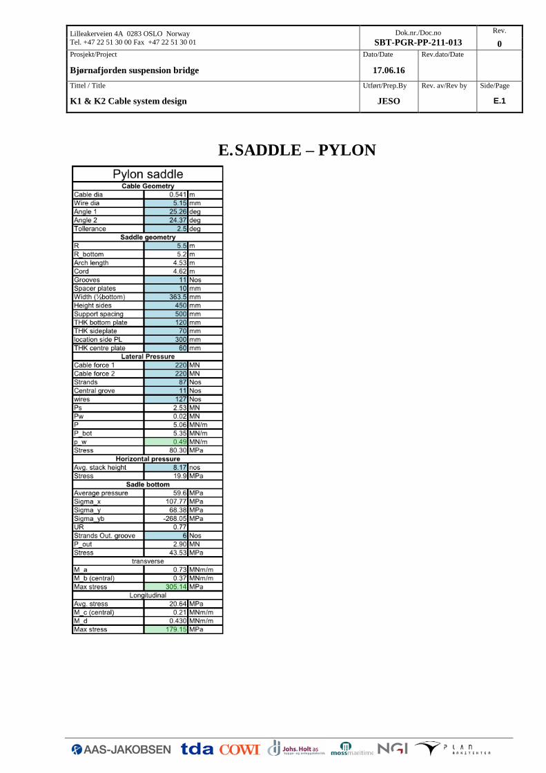
Lilleakerveien 4A 0283 OSLO Norway
Tel. +47 22 51 30 00 Fax +47 22 51 30 01
Dok.nr./Doc.no
SBT-PGR-PP-211-013
Rev.
0
Prosjekt/Project Dato/Date Rev.dato/Date
Bjørnafjorden suspension bridge 17.06.16
Tittel / Title Utført/Prep.By Rev. av/Rev by Side/Page
K1 & K2 Cable system design JESO E.1
E. SADDLE – PYLON

Lilleakerveien 4A 0283 OSLO Norway
Tel. +47 22 51 30 00 Fax +47 22 51 30 01
Dok.nr./Doc.no
SBT-PGR-PP-211-013
Rev.
0
Prosjekt/Project Dato/Date Rev.dato/Date
Bjørnafjorden suspension bridge 17.06.16
Tittel / Title Utført/Prep.By Rev. av/Rev by Side/Page
K1 & K2 Cable system design JESO E.2

Lilleakerveien 4A 0283 OSLO Norway
Tel. +47 22 51 30 00 Fax +47 22 51 30 01
Dok.nr./Doc.no
SBT-PGR-PP-211-013
Rev.
0
Prosjekt/Project Dato/Date Rev.dato/Date
Bjørnafjorden suspension bridge 17.06.16
Tittel / Title Utført/Prep.By Rev. av/Rev by Side/Page
K1 & K2 Cable system design JESO F.1
F. SPLAY SADDLE It should be noted that the splay saddle has been verified for a suspended cable load of 210MN,
however due to a change in the global model the load has increased to 274MN in ULS. However in
the calculation the support rib spacing has conservatively been set to the max value of 800mm
corresponding to the rear of the saddle. However only full loading occurs at the lead end of the
saddle where te rib spacing is < 700mm and if this spacing is used instead the splay saddle still has
sufficient capacity wit an increase of the bottom plate from 110mm to 120mm. Such a calculation is
introduced at the end of this appendix.

Lilleakerveien 4A 0283 OSLO Norway
Tel. +47 22 51 30 00 Fax +47 22 51 30 01
Dok.nr./Doc.no
SBT-PGR-PP-211-013
Rev.
0
Prosjekt/Project Dato/Date Rev.dato/Date
Bjørnafjorden suspension bridge 17.06.16
Tittel / Title Utført/Prep.By Rev. av/Rev by Side/Page
K1 & K2 Cable system design JESO F.2

Lilleakerveien 4A 0283 OSLO Norway
Tel. +47 22 51 30 00 Fax +47 22 51 30 01
Dok.nr./Doc.no
SBT-PGR-PP-211-013
Rev.
0
Prosjekt/Project Dato/Date Rev.dato/Date
Bjørnafjorden suspension bridge 17.06.16
Tittel / Title Utført/Prep.By Rev. av/Rev by Side/Page
K1 & K2 Cable system design JESO F.3

Lilleakerveien 4A 0283 OSLO Norway
Tel. +47 22 51 30 00 Fax +47 22 51 30 01
Dok.nr./Doc.no
SBT-PGR-PP-211-013
Rev.
0
Prosjekt/Project Dato/Date Rev.dato/Date
Bjørnafjorden suspension bridge 17.06.16
Tittel / Title Utført/Prep.By Rev. av/Rev by Side/Page
K1 & K2 Cable system design JESO F.4
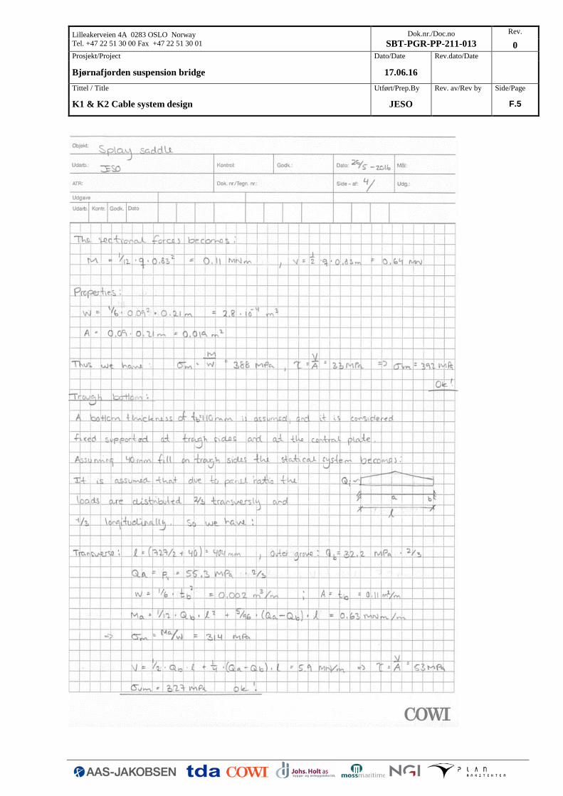
Lilleakerveien 4A 0283 OSLO Norway
Tel. +47 22 51 30 00 Fax +47 22 51 30 01
Dok.nr./Doc.no
SBT-PGR-PP-211-013
Rev.
0
Prosjekt/Project Dato/Date Rev.dato/Date
Bjørnafjorden suspension bridge 17.06.16
Tittel / Title Utført/Prep.By Rev. av/Rev by Side/Page
K1 & K2 Cable system design JESO F.5
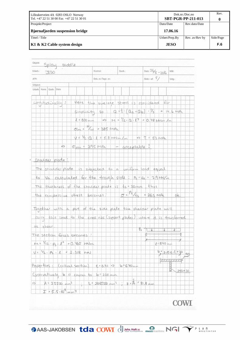
Lilleakerveien 4A 0283 OSLO Norway
Tel. +47 22 51 30 00 Fax +47 22 51 30 01
Dok.nr./Doc.no
SBT-PGR-PP-211-013
Rev.
0
Prosjekt/Project Dato/Date Rev.dato/Date
Bjørnafjorden suspension bridge 17.06.16
Tittel / Title Utført/Prep.By Rev. av/Rev by Side/Page
K1 & K2 Cable system design JESO F.6

Lilleakerveien 4A 0283 OSLO Norway
Tel. +47 22 51 30 00 Fax +47 22 51 30 01
Dok.nr./Doc.no
SBT-PGR-PP-211-013
Rev.
0
Prosjekt/Project Dato/Date Rev.dato/Date
Bjørnafjorden suspension bridge 17.06.16
Tittel / Title Utført/Prep.By Rev. av/Rev by Side/Page
K1 & K2 Cable system design JESO F.7

Lilleakerveien 4A 0283 OSLO Norway
Tel. +47 22 51 30 00 Fax +47 22 51 30 01
Dok.nr./Doc.no
SBT-PGR-PP-211-013
Rev.
0
Prosjekt/Project Dato/Date Rev.dato/Date
Bjørnafjorden suspension bridge 17.06.16
Tittel / Title Utført/Prep.By Rev. av/Rev by Side/Page
K1 & K2 Cable system design JESO F.8
Updated calculation example: