Embed Size (px)
Citation preview
4 y October 2008 y CompactPCI and AdvancedTCA Systems
Published by:
© 2008 OpenSystems Media/OpenSystems Publishing® CompactPCI, PICMG, AdvancedTCA, ATCA, MicroTCA, and their logos are
registered trademarks of the PCI Industrial Computer Manufacturers Group.TM AdvancedMC and CompactTCA are trademarks of the PCI Industrial Computer Manufacturers Group. © 2008 CompactPCI and AdvancedTCA SystemsAll registered brands and trademarks in CompactPCI and AdvancedTCA Systems are property of their respective owners.
www.compactpci-systems.com www.advancedtca-systems.com
Volu m e 12 • N u m be r 8
oCTober 20 08CompactPCI ®
AdvancedTCA ®and Systems
The Magazine for Developers of Open Communication, Industrial, and Rugged Systems
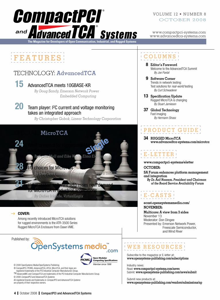
g COVER:Among recently introduced MicroTCA solutions for rugged environments is the ATR-3500 Series Rugged MicroTCA Enclosure from Dawn VME.
C O L U M N S 8 Editor’s Foreword Welcome to the AdvancedTCA Summit By Joe Pavlat
9 Software Corner Trends in network testing: Test solutions for real-world testing By Curt Schwaderer
13 Specification Update Rugged MicroTCA is changing By Stuart Jamieson
37 Global Technology Fast imaging By Hermann Strass
P R O D U C T G U I D E 34 RUGGED MicroTCA www.advancedtca-systems.com/microtca
E - L E T T E Rwww.compactpci-systems/eletterOCTOBER:SA Forum enhances platform management and integration By Dr. Asif Naseem, President and Chairman of the Board Service Availability Forum
E - C A S T Secast.opensystemsmedia.com/NOVEMBER:Multicore: A view from 3 sidesNovember 13Moderator: Don DingeePresented by: Emerson Network Power,
Freescale Semiconductor, and Wind River
Member since 1998
F E A T U R E S
TeCHNoloGY: AdvancedTCA
15 AdvancedTCA meets 10GBASE-KR By Doug Sandy, Emerson Network Power Embedded Computing
20 Team player: I2C current and voltage monitoring takes an integrated approach By Christopher Gobok, Linear Technology Corporation
SPeCIAl: MicroTCA
24 What to expect for ruggedized MicroTCA enclosure platforms By Justin Moll and Eike Waltz, Elma Electronic
28 I/O choices for MicroTCA By Uwe Tews and Peter Zimmermann, TEWS Technologies
31 Virtualization software addresses new demand for MicroTCA in industrial applications By Didier Irlande, VirtualLogix
W E B R E S O U R C E SSubscribe to the magazine or E-letter at:www.opensystems-publishing.com/subscriptions
Industry news:Read: www.compactpci-systems.com/newsSubmit: www.opensystems-publishing.com/news/submit
Submit new products at:www.opensystems-publishing.com/vendors/submissions/np
Single

6 y October 2008 y CompactPCI and AdvancedTCA Systems
A n O p e n S y S t e m S p u b l i c A t i O n
Communications Group n CompactPCI and AdvancedTCA Systems n C m ac P a d Ad an edT A R s u e ui e n C m a tP I nd A a cedT A lett
Editorial Director Joe P lat jpavl @ pensy t msmedia.com
Ma aging dito Ann Fis e [email protected]
Technology Editor Curt Schwaderer [email protected]
Senior Associate Editor Jennifer Hesse [email protected]
European Representative Hermann Strass [email protected]
Assistant Editor Robin DiPerna
Senior Designer Joann Toth
Senior Web Developer Konrad Witte
Web Content Specialist Matt Avella
Art Director David Diomede
Circulation/Office Manager Phyllis Thompson [email protected]
16872 E. Ave of the Fountains, Ste 203 Fountain Hills, AZ 85268Tel: 480-967-5581 n Fax: 480-837-6466Website: www.opensystemsmedia.com
Publishers John Black, Michael Hopper, Wayne Kristoff
Vice President Editorial Rosemary Kristoff
Embedded and Test & Analysis Group Editorial Director Jerry Gipper Editorial Director Don Dingee Senior Associate Editor Jennifer Hesse European Representative Hermann Strass
Military & Aerospace Group Group Editorial Director Chris Ciufo Associate Editor Sharon Schnakenburg Senior Editor (columns) Terri Thorson European Representative Hermann Strass
CompactPCI and AdvancedTCA Systems (USPS 019-288) is published nine times a year (Feb, March, April, May, June, July/Aug, Sept, Oct, Nov/Dec) by OpenSystems Media/OpenSystems Publishing LLC, 30233 Jefferson Avenue, St. Clair Shores, MI 48082. Print ISSN 1098-7622, Online ISSN 1550-0381.CompactPCI and AdvancedTCA Systems is free to qualified engineers or management dealing with or considering open system technologies. For others, paid subscription rates inside the US and Canada are $63/year. For first class deliver outside the US and Canada, subscriptions are $90/year (advance payment in US funds required) Periodica s postage paid at St. Clair Shores, MI, and at additional mailing offices. Canada: Publication agreement #40048627. Return undeliverable Canadian addresses to:
WD Station A, PO Box 54, Windsor, ON N9A 615.POSTMASTER: Send address changes to CompactPCI and AdvancedTCA Systems
16872 E. Ave of the Fountains, Ste 203, Fountain Hills, AZ 85268.
CompactPCI ®
AdvancedTCA ®and Systems
om acd anc dTC S
Single

8 y October 2008 y CompactPCI and AdvancedTCA Systems
By Joe Pavlat
CompactPCI and AdvancedTCA Systems CompactPCI and AdvancedTCA Systems CompactPCI and AdvancedTCA Systems CompactPCI and AdvancedTCA Systems
EDITOR’SFOREWORDWelcome to the
AdvancedTCA Summit
Hopefully you are attending the Summit in Santa Clara as you read this. This excellent conference, organized by Lance Leventhal and his crew at Conference Concepts, has become the premier event for showcasing AdvancedTCA and, now, MicroTCA technology. It is focused and is the place to be if you are interested in either of
these two important platforms. It is also a great “gathering of the clan,” where many of us get to spend a little face time with our colleagues with whom we exchange phone calls and e-mail during the rest of the year.
Airing out MicroTCA coolingSpeaking of MicroTCA, this technology continues to generate a lot of interest in the usual places and in some unexpected ones. The military’s keen interest, sparked by the platform’s management and high availability features, is driving changes to the ongoing expansion of the original standard.
Last year, it became clear that a more ruggedized version of the standard needed to be developed to address segments of the telecom industry that included outdoor equipment, including pole mounted and underground systems. This, of course, is largely related to storage and operational temperature range but not a lot of shock or vibration. Two technical development subcommittees were formed, one focusing on air cooling and the other on conduction cooling for really extreme environments. Then key military vendors, including Boeing and BAE Systems got involved and successfully convinced the group to expand the scope of the
efforts to include not just extended temperature ranges, but high levels of shock, vibration, EMC protection, and even higher temperature extremes.
Clearly defined testing requirements and methodologies are very important to military designers. It has become clear, as Stuart Jamieson of Emerson and Justin Moll and Eike Waltz of Elma explain in this issue, that a single specification – at least for the air-cooled variety – would serve neither the commercial nor the military customer’s needs. So it now looks like we’ll see separate specs for air-cooled commercial and air-cooled military versions.
10 GbE challengesThe release of the IEEE standards for 10 GbE create some real challenges for the AdvancedTCA and MicroTCA communities and PICMG, as one of the versions raises the data rate to over 10 Gbps on a single pair of conductors, whereas the existing PICMG standard for Ethernet over the backplane uses four pairs. Doug Sandy of Emerson is capably leading the effort within PICMG to update the AdvancedTCA Etherne definitions to accommodate the new standards, and his article in this issue is a useful primer on the activity.
Joe Pavlat, Editorial Director
Single

CompactPCI and AdvancedTCA Systems y October 2008 y 9
CompactPCI and AdvancedTCA Systems CompactPCI and AdvancedTCA Systems CompactPCI and AdvancedTCA Systems CompactPCI and AdvancedTCA Systems
By Curt SChwaderer
SOFTWARECORNER
Hearing the term network test equipment may cause visions of boxes that test the correctness of proto-cols to spring to mind. While it’s true that testing correctness of network protocols is an important part of lab validation, test equipment vendors are
striving to extend beyond simple test capabilities to model very complex subscriber services and their interactions. Creating test equipment that can accommodate testing of multi-service network environments is a very complex proposition indeed! In this month’s column, we’ll look at how Ixia, a leading IP-based test equipment company, achieves this next level of system test solutions.
BackgroundAnyone who has developed a product based on Internet Protocol (IP) is probably familiar with Ixia (http://ixiacom.com). Ixia is well known in the industry as one of the leading IP-based test equipment companies, having started in Ethernet and IP protocol testers early on. When Ixia began, IP was primarily used for Local Area Network (LAN) connectivity within the enterprise. Since those humble beginnings, IP has grown to be the de facto standard for multi-service network transport. Initiatives like the Metro Ethernet Forum (MEF), 3G and 4G wireless, and WiMAX promise to make IP the ubiquitous network layer for the global converged network.
As IP-based services have spread, so too has the complexity of validating IP-based devices. Ixia has adapted to meet these grow-ing test solution needs. One of the key success factors has been the company’s ability to partner with its customers to accelerate the development and deployment of converged IP networks and services.
The transition from simple protocol testing to a flexible configura-tion for multi-service network subscriber modeling is filled with challenges and complexity. I recently spoke with Sunil Kalidindi, Director of Product Management at Ixia, about how these new challenges are being met.
Test requirements and design strategyOne of the first requirements comes from the ability to provide a solution that allows the network operators to effectively utilize their CAPital EXpense (CAPEX) and OPerational EXpense (OPEX) dollars. From the design and product architecture perspective, preserving a single platform for doing all the required testing is important. This tends to be more complicated than it sounds. For example, Cisco makes a myriad of network infrastructure products that implement a number of switching and routing functions within the network. Ixia must supply a single form factor product with the ability to test and/or emulate all these functions. In order to achieve this, a load module approach that can be scaled within a multi-slot chassis has been used. Each load module is a plug-in card that runs a set of applications for testing Layer 2-7 functions. Currently Ethernet and Packet over SONET/ATM load modules are available that go up to 10 Gigabit and OC-192 respectively. This allows the test system to scale with the requirements of the testing to be performed.
The design of the load modules themselves is challenging. Each load module is a purpose-built hardware system tuned for high performance and designed to be scalable within a multi-slot chassis. These load modules are designed to allow hundreds of thousands of MAC addresses and millions of IP addresses for large-scale network testing. The underlying hardware components, involving high-speed CPUs and FPGAs containing optimized algorithms, enable the test environment to reach the performance targets necessary to test high-speed multi-service network testing.
A highly customized version of Linux is used to enable easy test application development, but the network stack within the Linux operating system must be bypassed to a large degree to enable the high-performance environment required by the load module applications. Sunil mentioned Ixia is spending more and more effort utilizing the new multi-core CPUs in the hope of increasing performance further.
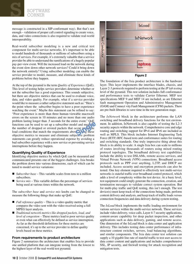
The complete real-world test pyramidIxia has an interesting perspective on test product strategy, as illustrated in Figure 1. A comprehensive test environment is modeled as a pyramid.
Trends innetwork testing:
Test solutions for real-world testing
The base of the pyramid is the traditional Layer 2-3 protocols that make up the foundation of traffic transport across the network. Protocols can be validated and performance measured at this layer of the pyramid.
The Layer 4-7 content switching adds another level of complexity. For example, testing the Session Initiation Protocol (SIP) can be problematic. While the individual elements of the messaging are well defined, how they are used to initiate a voice or data call can differ, depending on the equipment manufacturers of SIP servers and Voice over IP (VoIP) equipment. Testing must include validation of the individual message elements (that is, each
Figure 1
Single
10 y October 2008 y CompactPCI and AdvancedTCA Systems
message is constructed in a SIP-conformant way). But that’s not enough – validation of proper call control signaling to create voice, data, and video connections is also required to validate real-world interoperability.
Real-world subscriber modeling is a new and critical test component for multi-service networks. It’s important to be able to model hundreds of thousands or millions of subscribers using a mix of services. For example, it’s extremely valuable that a service provider be able to understand the ramifications of a hugely popular pay-per-view event. Will the increased load on the network during the event slow down other network services? Could it bring down the network entirely? Using subscriber modeling can enable the service provider to model, measure, and eliminate these kinds of problems before they happen.
At the top of the pyramid is the term Quality of Experience (QoE). This level of testing helps service providers determine whether or not the subscriber has a good experience. This sounds subjective, but there are objective metrics that can be used to evaluate voice, data, and video quality. For example, what if a service provider would like to measure a rather subjective statement such as: “Here’s the point where the subscriber begins to have a poor experience watching the event.” Maybe this statement can be refined to say: “Poor experience is more than three human-viewable macrocell errors on the screen in 10 minutes and no more than one audio problem lasting longer than .5 seconds for the entire event.” QoE functions can be used to set up a subscriber model and measure the number of dropped or errored packets that occur under the load conditions that match the requirements above Using these objective metrics to measure and eliminate subjective problem statements can greatly reduce operational expense by avoiding a bad subscriber experience with a new service or preventing service interruptions before they happen.
Quantifying Quality of ExperienceIdentifying objective metrics by which QoE can be measured and communicated presents one of the biggest challenges. Ixia breaks the problem down into various dimensions, each of which can be tuned to model service variations:
Subscriber base – This variable scales from tens to a million subscribers.Service mix – This variable defines the percentage of services being used at various times within the network.
The subscriber base and service mix knobs can be changed to measure the following things that make up QoE:
Full reference quality – This is a video quality metric that compares the video sent with the video received using a full MPEG layer analysis.Traditional network metrics like dropped packets, load, and level of congestion – These metrics lead to poor service quality or even what can effectively be defined as service interruption. As far as the threshold definitions for these metrics are concerned, it’s up to the service provider to define quality levels based on these metrics.
From requirements to product architectureFigure 2 summarizes the architecture that enables Ixia to provide one unified platform that can integrate testing from the lowest to the highest layer of the real-world test pyramid.
Figure 2
The foundation of the Ixia product architecture is the hardware layer. This layer implements the interface blades, chassis, and Layer 2-3 protocols required to perform testing at the IP lab testing level of the pyramid. This test solution includes full conformance and performance tests to validate Carrier Ethernet. MEF test specifications MEF 9 and MEF 14 are included, as are Ethernet fault management Operation and Administrative Management (OAM) and Connect vity Fault Management (CFM) packets. There are pre-built libraries to save time in the test generation stage.
The IxNetwork block in the architecture performs the LAN switching and broadband delivery functions for the test environ-ment. In addition, IxNetwork is also capable of testing the L2-3 security aspects within the network. Comprehensive core and edge routing and switching support for IPv4 and IPv6 are included as well as MPLS. This block includes Internet Engineering Task Force (IETF) RFC-based tests and conformance suites for routing and switching standards. One truly impressive thing about this block is its ability to scale: A single Ixia box can scale to millions of routes involving thousands of routers using mixed routing protocol topologies. The broadband delivery test capabilities include the ability to test DSLAMs, remote access services, and Virtual Private Network (VPN) connections. Broadband access protocols such as PPP over anything, L2TP, and DHCP are included. Access security and encryption protocols can also be tested. One key element required to effectively test multi-service networks is stateful traffic over broadband control protocol, which adds a level of complexity within the test device. At a basic level, test equipment could simply generate the connection, creation, and termination messages to validate correct system operation. But for multi-play traffic and QoE testing, this isn’t enough. The test device(s) must keep track of the connections being made, perform content delivery and analysis, and keep track of traffic loads versus connection frequencies and data delivery during system testing.
The IxLoad block implements the traffic loading environment for various services within the multi-service network. These services include video delivery, voice calls, Layer 4-7 security applications, content-aware capability for deep packet inspection, and other applications such as data delivery, gaming, and remote access. One dimension of the IxLoad block is data center and application delivery. This includes testing data center performance of infra-structure content switches, servers, load balancing algorithms, and similar components. The Ixia data center test solution can supply a 10 gigabit line rate of stateful traffic to test user access to data center content and applications and includes comprehensive SSL, IP security, and firewall testing for attack recognition and mitigation tests.
Single

CompactPCI and AdvancedTCA Systems y October 2008 y 11
VoIP test solutionsIxia’s solution includes SIP testing in terms of protocol conformance and loading tests. The user can set up real-world subscribers and usage models on top of the IxNetwork capabilities and test true Quality of Experience.
Each of the functional blocks in the Ixia architecture may be tied together with Ixia’s Test Conductor. This component provides an interface between the tester and the functional blocks. The tester uses this interface to define the level of the test and configure the blocks for traffic mix, subscriber model, and other parameters. Test Conductor enables regression tests ranging from low-layer interface and protocol testing to subscriber profiling and traffic load testing at the system level.
Figure 3 shows how the tester can create automated regression tests with these high-level device and system testing capabilities.
First, the tester defines the Device/System Under Test (DUT/SUT). The next step is to configure the device/system for the specific test. The Ixia test solution is used to configure the test equipment once the test environment is set up. From there, the test is executed, results analyzed, and updates or verification is performed.
The Ixia test equipment helps at each stage of this life cycle. Use of the graphi-cal interface to perform automated DUT configuration provides easy test definitions. Employing the equipmen also makes it possible to determine the traffic configuration to use, to test the flow control for mix and frequency of traffic, and to display results and generate reports for test analysis. Over time, the test reports can be used to see device performance trends as device capabilities increase. Ixia includes an extensive set of pre-built libraries to facilitate creation of the device and system tests. Ixia also supports Tcl, which is commonly used for test scripting, so legacy or third-party tests can be integrated into the test system.
SummaryAs we continue to drive toward a global IP multi-service network, it’s no longer enough to validate equipment at the physical inter-face and connection protocol level. Multi-service networks demand the ability to understand and evaluate much higher level metrics in order to deliver reliable, enjoyable services from voice to video, data to gaming. The Ixia suite of test solutions provides an impressive mix of capabilities at all levels of the real-world test pyramid.
For more information, contact Curt at [email protected].
Figure 3
Single
CompactPCI and AdvancedTCA Systems y October 2008 y 13
Rugged MicroTCA is changingRugged MicroTCA (I won’t call the specification MicroTCA.1 or
MicroTCA.2 for reasons I shall explain later) is going through a period of transformation. This transformation is a direct result of new requirements that have recently been identified by PICMG’s Rugged MicroTCA subcommittee. In order to address these newly identified requirements, there has been a slight adjustment in the subcommittee’s current focus and direction.
In May 2008, the Rugged MicroTCA specification was split into two parts, the air-cooled specification and the conduction-cooled specification. Recognizing that the conduction-cooled specification had different needs and requirements, PICMG formed a separate subcommittee to address these specific issues. This new subcommittee comprises a different experience base to ensure its members have the necessary expertise to bring the specification forward. The conduction-cooled MicroTCA subcommittee is currently working to gather requirements and investigate solutions to move MicroTCA (with the maximum amount of reuse of MicroTCA.0 and AMC.0) into the conduction-cooled space.
Air-cooled specification split recommendedThe newly formed conduction-cooled subcommittee has had an impact on the air-cooled subcommittee. Given the newly identified, developed, and disclosed customer requirements, it’s clear that the air-cooled specification must take on both extra functionality and allowance in order to address the diverse markets identified in the statement of work.
The subcommittee is currently identifying and localizing these new requirements. As a direct result of this analysis, a proposal to split the air-cooled specification into two documents has been recommended. The first document was originally proposed as an extension of the MicroTCA.0 environmental requirements, allowing MicroTCA.0 to function within extended temperature and shock/vibration environments. Discussions led to this first document becoming a stand-alone dot spec in its own right. This specification is perceived, at this stage, to apply to telco-centric, industrial, transportation, and low-end military applications.
The second air-cooled specification will focus on more severe operational environments, including higher/lower temperatures, temperature cycling, random vibration, greater g shock requirements for longer periods of time, and the like. This specification may also look at areas such as two-level maintenance, Electrical Static Discharge (ESD), and contamination protection. These requirements are all focused on military and aerospace applications.
The subcommittee also intends to add a short guidance document to the specification and requirement alignments. Such a guide will allow implementers/architects to quickly identify which specification can be used for which application, as well as the environmental conditions that the specification supports. This will aid the understanding of MicroTCA users in general and help organize and explain the final specification-naming conventions.
What’s in a name …A final consideration is what the specifications should be called. The subcommittee proposed and discussed two possibilities. One possibility was that the telco-specific air-cooled specification would become an extension document of MicroTCA.0, while the military-focused air-cooled specification should be called MicroTCA.1. The other suggestion was that the telco- specific air-cooled specification would become MicroTCA.1, and the military- focused specification would become MicroTCA.3.
However, the subcommittee’s final decision is that for development purposes, the specifications currently under development will be named MicroTCA.X, MicroTCA.Y, and MicroTCA.Z. The actual numbering of those specifications was considered unimportant at this stage and will be dealt with as the specification reaches the release candidate stage.
SummaryAs it currently stands, the Rugged MicroTCA subcommittee(s) will be releasing three specifications and one overall application/alignment guide. The three specifications will cover:
Air-cooled MicroTCA.0 at extended shock/vibration and temperature, focused on telco-centric, industrial, and transportation applicationsAir-cooled MicroTCA.0 at more extreme shock/vibration and temperature, including such things as contamination, ESD, and two-level maintenance, focused on more environmentally challenging aerospace and military applicationsConduction-cooled MicroTCA.0 applications dealing with shock/vibration and temperature, in addition to such factors as contamination, ESD, and two-level maintenance, focused on military applications and possibly aggressive telco applications
It’s important to understand that the subcommittees are working to address the required markets with a strong set of rigorous, qualified specifications. These new specifications are practically focused, built with strong customer input, and backed up with testing strategies and test results.
Stuart Jamieson is Director, Industry Relations/Architect for the Embedded Computing business of Emerson Network Power and the editor on the PICMG MicroTCA.2 and the Interconnect Channel Subcommittee, as well as introduction author for MicroTCA.1.
For more information, contact Stuart at [email protected].
By Stuart JamieSon
Single
CompactPCI and AdvancedTCA Systems y October 2008 y 15
AdvancedTCATECHNOLOGY g
By doug Sandy
In March of 2007, IEEE approved 802.3ap, standardizing the physical layers for
Ethernet over electrical backplanes. The specification included a 1 Gb Ethernet
interface and two 10 Gb Ethernet interfaces: 10GBASE-KX4 and 10GBASE-KR.
PICMG is currently at work incorporating these new standards into AdvancedTCA.
Doug surveys the new IEEE backplane Ethernet standards and ongoing PICMG
activities and discusses the possible future of Ethernet’s AdvancedTCA prospects.
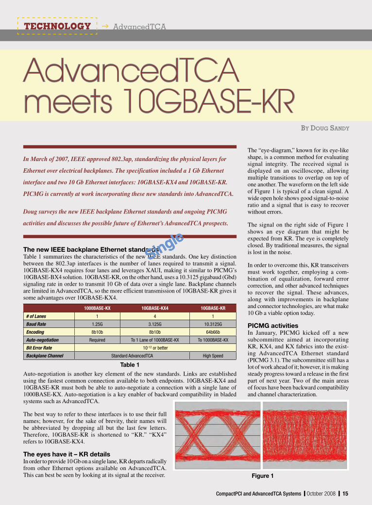
The new IEEE backplane Ethernet standardsTable 1 summarizes the characteristics of the new IEEE standards. One key distinction between the 802.3ap interfaces is the number of lanes required to transmit a signal. 10GBASE-KX4 requires four lanes and leverages XAUI, making it similar to PICMG’s 10GBASE-BX4 solution. 10GBASE-KR, on the other hand, uses a 10.3125 gigabaud (Gbd) signaling rate in order to transmit 10 Gb of data over a single lane. Backplane channels are limited in AdvancedTCA, so the more efficient transmission of 10GBASE-KR gives it some advantages over 10GBASE-KX4.
The “eye-diagram,” known for its eye-like shape, is a common method for evaluating signal integrity. The received signal is displayed on an oscilloscope, allowing multiple transitions to overlap on top of one another. The waveform on the left side of Figure 1 is typical of a clean signal. A wide open hole shows good signal-to-noise ratio and a signal that is easy to recover without errors.
The signal on the right side of Figure 1 shows an eye diagram that might be expected from KR. The eye is completely closed. By traditional measures, the signal is lost in the noise.
In order to overcome this, KR transceivers must work together, employing a com-bination of equalization, forward error correction, and other advanced techniques to recover the signal. These advances, along with improvements in backplane and connector technologies, are what make 10 Gb a viable option today.
PICMG activitiesIn January, PICMG kicked off a new subcommittee aimed at incorporating KR, KX4, and KX fabrics into the exist-ing AdvancedTCA Ethernet standard (PICMG 3.1). The subcommittee still has a lot of work ahead of it; however, it is making steady progress toward a release in the first part of next year. Two of the main areas of focus have been backward compatibility and channel characterization.
Auto-negotiation is another key element of the new standards. Links are established using the fastest common connection available to both endpoints. 10GBASE-KX4 and 10GBASE-KR must both be able to auto-negotiate a connection with a single lane of 1000BASE-KX. Auto-negotiation is a key enabler of backward compatibility in bladed systems such as AdvancedTCA.
The best way to refer to these interfaces is to use their full names; however, for the sake of brevity, their names will be abbreviated by dropping all but the last few letters. Therefore, 10GBASE-KR is shortened to “KR.” “KX4” refers to 10GBASE-KX4.
The eyes have it – KR detailsIn order to provide 10 Gb on a single lane, KR departs radically from other Ethernet options available on AdvancedTCA. This can best be seen by looking at its signal at the receiver.
1000BASE-KX 10GBASE-KX4 10GBASE-KR
# of Lanes 1 4 1
Baud Rate 1.25G 3.125G 10.3125G
Encoding 8b10b 8b10b 64b66b
Auto-negotiation Required To 1 Lane of 1000BASE-KX To 1000BASE-KX
Bit Error Rate 10-12 or better
Backplane Channel Standard AdvancedTCA High Speed
Table 1
Figure 1
CompactPCI and AdvancedTCA Systems y October 2008 y 15
AdvancedTCAmeets 10GBASE-KR
Single

16 y October 2008 y CompactPCI and AdvancedTCA Systems
Backward compatibilityOne of the key goals of the PICMG 3.1 R2.0 subcommittee is to ensure backward com-patibility with existing AdvancedTCA platforms. This means that Ethernet boards designed to work with 1000BASE-BX and BX4 PICMG interfaces should plug-and-play in KX4 and KR platforms. Likewise, blades with KR or KX interfaces should work in BX-enabled platforms.
Although this sounds simple in concept, there are a very large number of combinations that must be accounted for to make this work. To understand just how much complexity is involved, see Table 2, which shows a few of many backward-compatibility scenarios.
In the first scenario, a 10GBASE-KX4 blade is plugged into an existing system, connecting it with a BX4-enabled endpoint. The most reasonable operation is to attempt connection using 10GBASE-BX4, given that the KX4 PHY may be capable of supporting BX4 operation as well. This connection needs to occur without requiring e-keying or management sub-system changes to the existing system.
In the next case, a KX4 endpoint is con-nected to a single lane of 1000BASE-BX. KX4 is required to auto-negotiate down to one lane of 1000BASE-KX, and 1000BASE-KX and 1000BASE-BX are similar, so the most reasonable operation is to attempt connection using 1000BASE-BX. Again, no changes to the existing system are allowed.
The last scenario is the most challenging of them all. In this case, two KR-enabled endpoints are placed in an existing system. We know the backplane will likely not support the 10.3125 Gbd symbol rate required, and the desired operation is for these blades to link up at 1.25 Gbd (1 Gb data rate). If, however, these same blades are placed in a backplane that supports higher speed signaling, a 10.3125 Gbd should be allowed. Backplane-specific e-keying behavior was not anticipated in the original AdvancedTCA specification.
The PICMG 3.1 R2.0 subcommittee has spent a great deal of time focusing on these and other scenarios to make sure that backward compatibility with existing AdvancedTCA platforms is maintained in a straight-forward and intuitive manner while still allowing higher speed operation in newer, 10.3125 Gbd-enabled platforms.
Communication channel characterizationThe second major issue that the PICMG 3.1 subcommittee faces has to do with inter- operability of KR components: the speci-fication, measurement, and testing of a 10.3125 Gbd communication channel.
In communications theory, a channel consists of everything along the path that connects a transmitter to a receiver. In AdvancedTCA, this means the circuit traces on the blades and backplane, the passive components, and the connectors.
Accumulation of electrical losses or noise within the channel can contribute to bit errors at the receiver. To control these bit errors, communications channels must be built according to parameters required by the signaling technology. Typical parameters include characteristic impedance, insertion loss, return loss, and
Endpoint 1 Endpoint 2 Backplane Result
10GBASE-KX4 10GBASE-BX4 Standard 10GBASE-BX4
10GBASE-KX4 1000BASE-BX Standard 1000BASE-BX
10GBASE-KR 10GBASE-KR Standard 1000BASE-KX
Table 2
Single

CompactPCI and AdvancedTCA Systems y October 2008 y 17
cross talk. In general, the higher the speed of the transmitted signal, the more important and tightly controlled these parameters become.
In order for the AdvancedTCA 10GBASE-KR ecosystem to flourish, the channel needs to be specified so that solutions from different suppliers can be developed independently yet still have a reasonable chance of working together. At the same time, the channel requirements can’t be so overdesigned that they unnecessarily increase cost due to esoteric materials requirements or experimental fabrication techniques.
Although IEEE 802.3ap provides some guidelines for 10GBASE-KR channel charac-teristics, they can’t be directly applied to AdvancedTCA. At the time of the writing of this article, the PICMG 3.1 subcommittee was working on strategies for characterizing the channel that meets all the requirements for KR interoperability. In addition, the PICMG Interconnect Characterization subcommittee is looking at channel specification, testing, and measurement as applied generally to all PICMG standards.
What KR Ethernet meansWith all this extra work to incorporate 10GBASE-KR into AdvancedTCA, you might be wondering “why bother?” After all, AdvancedTCA already has a 10 Gb backplane standard, 10GBASE-BX4. Does it really need another? The answer is yes, and perhaps some of the best reasons to pay attention to 10GBASE-KR are bandwidth scalability, flexibility, and future-proofing.
AdvancedTCA defines a blade’s fabric channel as a collection of four “ports.” For 10GBASE-BX4 operation, all of these ports are used to make a connection. KR operation, on the other hand, requires only one “port,” leaving the other three free for additional signaling (see Figure 2). System designers are now free to provide 20, 30, or even 40 Gb of fabric channel connectivity to any blade that requires it – something that is impossible to do with BX4.
A second advantage of KR over BX4 and KX4 is that it is more flexi le. Although some older BX4 transceivers can support connection at 1 Gb rates, they are not required to
Figure 2
support this connection rate. And while KX4 will auto-negotiate down to a KX link, it is limited to one lane (1 Gbps) of connection. This means that boards with multiple ports of BX connectivity, such as options 1, 2, or 3, will only be able to connect the first port. On the other hand, every KR lane is capable of connecting at 1 Gbps (KX) rates. All of the previous options could be supported.
A third reason to consider a KR-enabled system is future-proofing. IEEE 802.3ba is now working on the specification of a true 40 Gb backplane standard: 40GBASE-KR4. Due to the way in which 10GBASE-KR is being leveraged to create 40GBASE-KR4, a reasonably constructed 10GBASE-KR backplane should be able to support 40GBASE-KR4 when the time comes.
CompactPCI and AdvancedTCA Systems y October 2008 y 17
Single

18 y October 2008 y CompactPCI and AdvancedTCA Systems
The future of Ethernet on AdvancedTCAAs stated earlier, PICMG 3.1 work is ongoing with hopes of completion in the first part of 2009 (see Figure 3). In 2009 and 2010 we should see KR components (PHYs and switches) and platforms with increasing port densities and sophistication. In 2010 IEEE 802.3ba is targeting completion. This introduces 40GBASE-KR4 true 40 Gb backplane Ethernet to the market. Soon after, it should be incorporated into a future PICMG 3.1 specification with platforms available as early as 2011.
Doug Sandy is the Senior Staff Technologist of the Technology and Strategy Department for the Embedded Computing business of Emerson Network Power. Doug is responsible for evaluating the performance of computer systems, constructing models for the systems, and predicting the systems’ behavior. He also chairs PICMG 3.1 R2.0, the subcommittee working on bringing 802.3ap Ethernet into AdvancedTCA. Doug holds a Bachelor’s and Master’s degree in Electrical Engineering from California Polytechnic State University, San Luis Obispo.
Emerson Network Power Embedded Computing
www.emersonnetworkpower.com/embeddedcomputing
What is in the future for AdvancedTCA after 40 Gb? Is 100 Gb possible without major overhauls? Even using four lanes, signaling rates in excess of 25 Gbd would be required At one time the probable answer would have been that this is completely out of the question. However, with continued advances in PHY, connector, and backplane technologies, who knows what the future might hold? After all, even a few years ago 10GBASE-KR would have seemed out of reach.
Figure 3
Single

20 y October 2008 y CompactPCI and AdvancedTCA Systems
TECHNOLOGY g AdvancedTCA
A variety of components is necessary to monitor the power input to a system. To measure current, a sense resistor and amplifier are needed, and it is most convenient if the amplifier common-mode range extends to the positive supply rail and translates its output to ground. Precision resistive dividers are needed to measure voltage and, if there is more than one voltage to monitor, a mux must also be added to the list. An Analog-to-Digital Converter (ADC) comes next, with a precise reference and some means of interfacing to a microprocessor, while perhaps sharing I/O lines with neighboring ICs. Because of the overall complexity and difficulty of finding suitable components, supply monitoring lends itself to an integrated solution.
Figure 1 shows the functional blocks needed to form a complete power monitoring system able to operate over a 7 V to 80 V range while monitoring current at the supply rail, its own supply voltage, and one additional voltage input. In developing such a system, making the sense resistor external adds flexibility and lets it accurately monitor currents ranging from milliamps to amps or more. Its ADC has 12-bit resolution and a Total Unadjusted Error (TUE) of 1 percent for voltage and 1.25 percent current. The external ADIN input TUE is just 0.75 percent. Digital communications are conducted over I2C, with a choice of nine device addresses.
Integrating all of the necessary functional blocks in a single-chip solution makes power monitoring practical in applications where a discrete solution is out of the question due to space or cost.
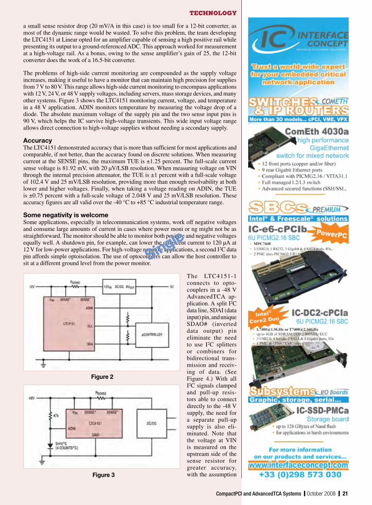
Meeting the needs of space-constrained applicationsRAID systems, telecommunications, and industrial computer/control systems are among the applications that are complex, space-constrained, and low-voltage. To address these challenges, it is best to keep connections to the power monitoring solution simple and to have only a few connections. A small MS10 or tiny 3 mm x 3 mm DFN package can be used. Depending on the system, the monitoring IC could be located on the backplane or on a removable card. Figure 2 shows location on a removable card. The high-voltage I2C current and voltage monitor in Figure 2 is the LTC4151 from Linear Technology. It is monitoring the input current and voltage to a 12 V DC/DC converter. Here, the low- voltage input, ADIN, is used to measure the 5 V output of the converter, while a direct I2C connection is made to the microprocessor. The only required external components are a sense resistor, two bus pull-up resistors, and a resistive divider for 5 V measurement on ADIN.
Low side or high side?Because of the inherent simplicity, low-side sensing, where the sense resistor is placed in series with the ground of the load, is an attractive means of monitoring supply current. It eliminates the need for a special amplifier by allowing the ADC to measure the sense resistor’s voltage drop either directly or with a simple preamplifier. Unfortunately, few loads are truly floating in such a way as to permit opening the ground path. This scheme also presents a potential safety hazard: A failed or disconnected low-side sense resistor allows the load ground to rise to the full supply voltage.
For these reasons, high-side sensing is almost always preferred, yet difficult to accomplish. This is because the ADC must measure the drop across a sense resistor that is connected to the positive rail, often at a voltage far outside the reach of the ADC itself. In addition,
By ChriStoPher goBok
Figure 1
Team player:I2C currentand voltage monitoring takes an integrated approach
As today’s electronic
designs continue to grow
in complexity, managing
power consumption and optimiz-
ing overall efficiency become
even more important. Christopher
describes the building blocks
needed for accurate power supply
voltage and current monitoring
– crucial to conserving power
and guaranteeing reliability in
everything from industrial and
telecom applications to automotive
and consumer electronics.
Single
a small sense resistor drop (20 mV/A in this case) is too small for a 12-bit converter, as most of the dynamic range would be wasted. To solve this problem, the team developing the LTC4151 at Linear opted for an amplifier capable of sensing a high positive rail while presenting its output to a ground-referenced ADC. This approach worked for measurement at a high-voltage rail. As a bonus, owing to the sense amplifier’s gain of 25, the 12-bit converter does the work of a 16.5-bit converter.
The problems of high-side current monitoring are compounded as the supply voltage increases, making it useful to have a monitor that can maintain high precision for supplies from 7 V to 80 V. This range allows high-side current monitoring to encompass applications with 12 V, 24 V, or 48 V supply voltages, including servers, mass storage devices, and many other systems. Figure 3 shows the LTC4151 monitoring current, voltage, and temperature in a 48 V application. ADIN monitors temperature by measuring the voltage drop of a diode. The absolute maximum voltage of the supply pin and the two sense input pins is 90 V, which helps the IC survive high-voltage transients. This wide input voltage range allows direct connection to high-voltage supplies without needing a secondary supply.
AccuracyThe LTC4151 demonstrated accuracy that is more than sufficient for most applications and comparable, if not better, than the accuracy found on discrete solutions. When measuring current at the SENSE pins, the maximum TUE is ±1.25 percent. The full-scale current sense voltage is 81.92 mV, with 20 µV/LSB resolution. When measuring voltage on VIN through the internal precision attenuator, the TUE is ±1 percent with a full-scale voltage of 102.4 V and 25 mV/LSB resolution, providing more than enough resolvability at both lower and higher voltages. Finally, when taking a voltage reading on ADIN, the TUE is ±0.75 percent with a full-scale voltage of 2.048 V and 25 mV/LSB resolution. These accuracy figures are all valid over the -40 °C to +85 °C industrial temperature range.
Some negativity is welcomeSome applications, especially in telecommunication systems, work off negative voltages and consume large amounts of current in cases where power moni or ng might not be as straightforward. The monitor should be able to monitor both positive and negative voltages equally well. A shutdown pin, for example, can lower the quiescent current to 120 µA at 12 V for low-power applications. For high-voltage negative applications, a second I2C data pin affords simple optoisolation. The use of optocouplers can allow the host controller to sit at a different ground level from the power monitor.
The LTC4151-1 connects to opto-couplers in a -48 V AdvancedTCA ap- plication. A split I2C data line, SDAI (data input) pin, and unique SDAO# (inverted data output) pin eliminate the need to use I2C splitters or combiners for bidirectional trans-mission and receiv-ing of data. (See Figure 4.) With all I2C signals clamped and pull-up resis-tors able to connect directly to the -48 V supply, the need for a separate pull-up supply is also eli-minated. Note that the voltage at VIN is measured on the upstream side of the sense resistor for greater accuracy, with the assumption
Figure 2
Figure 3
CompactPCI and AdvancedTCA Systems y October 2008 y 21
Single

22 y October 2008 y CompactPCI and AdvancedTCA Systems
Figure 4
that the quiescent current of the LTC4151 is negligible when compared to the load of a DC/DC converter, which is usually on the order of amperes for AdvancedTCA applications. Figure 4 also demonstrates how the ADIN pin can be used to measure the board temperature using a thermistor.
Regardless of whether or not an applica-tion requires isolation, there are monitor features that can prove convenient when reporting back to a polling host. For example the use of a stuck-bus reset timer that resets the internal I2C state machine allows nor-mal communication to resume in the event that I2C signals are held low for more than 33 ms (stuck bus condition). Otherwise, the LTC4151 can report data continuously
or in a single snapshot mode. In continuous scan mode, the LTC4151 measures the voltage between the SENSE pins, at VIN, and at ADIN sequentially at a 7.5 Hz refresh
rate. In snapshot mode, the host controller instructs the LTC4151 to perform a one-time measurement on any of the signals, useful for applications that only need to measure input power on occasion.
ConclusionWhen faced with the challenge of solving a wide range of applications, traditional high-voltage current and voltage monitor-ing implementations using discretes and other power monitors tend to fall short in the areas of complexity, functionality, and performance. A “team” approach employing high-performance building blocks, including the internal sense amplifier, Delta Sigma ADC, and I2C interface, ensures that digital readings are accurate and precise. High-voltage applications can take advantage of the 90 V Abs Max rating, while all of the IC’s flexibility applies to users monitoring negative voltages, including an isolation-friendly option. Designers can now spend less time on implementing a reliable power monitoring scheme.
Christopher Gobok is a Product Marketing Engineer for mixed signal products at Linear Technology. Chris graduated from San Jose State University with a BSEE, MSE, and MBA. His previous industry experience includes working as a product marketing engineer with optoelectronics and power MOSFETs.
Linear Technology Corporation www.linear.com
Single

+44 (0)1383 735161 www.simclar.com email:[email protected]
TurboFabricTM Scalable ATCA Platforms enable Vision to become Reality - by providing the performance required to future
proof your ATCA application.
Featuring 40GigE enabled Full Mesh and Dual Star Backplane options, TurboFabricTM Platforms provide the bandwidth scalability needed to broaden the application space of ATCA, significantly extending future ATCA Product Life Cycles and improving ROI for System Integrators and Service Providers.
And with a thermal management system that can deliver an astonishing 50+5 CFM/slot of cooling capacity, TurboFabricTM Platforms not only meet but exceed the stringent volumetric and uniform airflow demands of CP-TA ICD Class B.4, enabling even the most challenging thermal application
needs to be addressed.
TurboFabricTM
making vision reality......
All TurboFabricTM 40GigE BackplaneChannels conform to
IEEE 803.2ap 10GBaseKR
TurboFabricTM Chassis Thermal ManagementSystem is Tested to CP-TA v1.1
Single

24 y October 2008 y CompactPCI and AdvancedTCA Systems
Figure 1
While there have been some custom rugged designs for
MicroTCA, the Rugged MicroTCA specifications are still
in draft form, as noted in this month’s Specification Update
column, page 13. Justin and Eike explain what changes to expect, factoring
in the level of ruggedization and cooling method.
MicroTCA is gaining acceptance in more applications and markets. Although originally geared for telecom core and edge applica-tions, MicroTCA’s form factor, manageability, wealth of vendors, performance/cost potential, open specification, and other factors make it a strong fit for many designs. It is expected to do well in telecom, medical, industrial, and military/aerospace markets (once the PICMG MicroTCA MIL/Aero specifications are completed). Some of the larger design wins today have already come in military programs, although in relatively benign environments, typically addressed by “cocooning” MicroTCA.0 solutions into an ATR box.
It is believed by many in the industry that MicroTCA could be well-suited for mil-aero applications. There are only a few high-bandwidth architectures with manageability addressed that have MicroTCA’s potential in military designs, particularly with its smaller form factor possibilities. Size and weight are common concerns in the mil-aero apps, and with MicroTCA’s well-known AdvancedMCs widely available, the architecture could be a hit. Questions to answer are: “How can we make MicroTCA rugged enough for military environments?” and “What is the definition of rugged?”
Rugged MicroTCARugged MicroTCA specifications are currently being developed by PICMG subcommittees. (See the Specification Update column in this issue.) Although some companies like Elma have announced ruggedized MicroTCA versions, one should not claim to have an actual specification-compliant rugged MicroTCA enclosure at this time. The PICMG MicroTCA specifications that define ruggedized versions are in draft stage.
An ATR box for ruggedized MicroTCA applications When the specification is complete, a rugged MicroTCA.X Extended Environment air-cooled chassis might look similar to the unit in Figure 1. Figure 1 shows an Elma Mektron air-cooled ruggedized MicroTCA chassis concept that passed MIL-STD-810E shock/vibration requirements and MIL-STD-461 for electromagnetic interference.
The chassis example is an ARINC 404A full-size ATR long enclosure, often used in commercial and military aviation. It seems that it will be very difficult for MicroTCA to pass military shock/vibration test standards without some modifications. Nobody wants to change the AdvancedMCs, which have been in the marketplace for several years now, thus the chassis and/or front panels will have to change. The unit in this example was tested with
SPECIAL g MICROTCA
By JuStin moll and eike waltz
modified front panels on the AdvancedMC modules (to become an option to be specified in MicroTCA.X Extended Environment) secured to the subrack for extra shock and vibration protection. Testing confirmed that this “standard” chassis configuration met the MIL-STD-810E shock/vibration requirements and MIL-STD-461 for electromagnetic interference. The vibration and shock tests were performed according to the IEC 61587 1 and VITA 47 standards in six axes (three spatial axes, with the system rotated by 180 degrees for each axis).
Although in this case modified front panels were used, in the forthcoming MicroTCA.X Extended Environment specification, the required subrack-to-module interface will be incorporated as an option. Noteworthy is that for this option to work, the subrack overall depth test dimensions will need to be reduced by 0.8 mm. This subrack depth reduction may result in an update to a later MicroTCA.0 issue (Figure 2). The proposed subrack/module interface for Rugged MicroTCA has the subrack overall depth dimensions reduced by 0.8 mm. Therefore, the chassis and/or face plates will likely be slightly different than nonrugged MicroTCA.
The new subrack/module interface allows the use of existing module face plates (AMC.0 defined) and/or the optionally defined face plates with retention (defined in MicroTCA.X Extended Environment).
What to expect for ruggedized MicroTCA
enclosure platforms
Single

CompactPCI and AdvancedTCA Systems y October 2008 y 25
Figure 2
Recapping MicroTCA’s evolutionMicroTCA grew out of the original AdvancedTCA specification (PICMG 3.0), which was aimed at the Telco Carrier Grade environment. AdvancedTCA needed the feature of mezzanine boards, which led to the development of the AdvancedMC standard (AMC.0). Telco and industrial, as well as mil and aerospace applications, demanded AdvancedMC modules outside the AdvancedTCA/AdvancedMC carrier environment. This led to the expansion of AdvancedMC modules’ role as direct-plug backplane technology – which became MicroTCA – with AdvancedTCA management functionality incorporated via MicroTCA carrier hubs and power modules. It made sense, given MicroTCA’s roots, that up to this point the contributing committee members were telco-centric, ensuring that the telco environmental needs were addressed.
Attention has been drawn to the needs of more extreme environments, including a considerably more severe random vibration environment (versus less severe seismic Zone 4 or sinusoidal vibration testing), ESD protection, bench handling, and rear I/O, just to name a few. These needs require specific mil testing and documentation not yet undertaken.
This issue presents a classic case of whose shoes you wear. Telco applications are known to be high volume and cost sensitive, while mil-aero applications are typically lower quantity and solution driven.
Conduction-cooled Rugged MicroTCAFor the conduction-cooled Rugged MicroTCA.Z chassis, the subcommittee’s work has just begun. The chassis may look very similar to a typical conduction-cooled chassis. Figure 2 shows a chassis design concept in use now.
We may see a wide range of cooling designs for Rugged MicroTCA. A conduction-cooled MicroTCA chassis with an external fan can be seen in Figure 3. The conduction-cooled boards are in a
Figure 3
sealed compartment with a separate compartment with a fan to expel excess heat. The airflow runs front-to-rear in this configuration. Again, what emerges from the MicroTCA.2 specification might differ from these examples.
Other chassis typesRugged MicroTCA may come in various forms. For example, rack-mount versions are on the horizon. See Figure 4, which depicts a ruggedized MicroTCA chassis concept in a 19" rack-mount format.
Figure 4
Single

26 y October 2008 y CompactPCI and AdvancedTCA Systems
Like the ATRs, the 19" rack-mount Rugged MicroTCA chassis can leverage the same type of shock-isolated card cage and device mounting that exists in other rugged designs.
Liquid cooling Liquid-cooled versions are certainly a possibility for systems with more intense cooling demands. One concern would be the increased costs. Liquid cooling can be very complex and costly. However, there are ways to get improved thermal performance in applications where forced airflow is not available. One such possibility is with Liquid Heat Exchange (LHE). Instead of having the liquid go through the individual modules or via a spray method, given that method’s associated costs and complications, the liquid can simply go through the outer chassis walls.
For cooling the standard MicroTCA conduction-cooled boards, the chassis sidewalls can be specially designed to carry various liquids (de-ionized water, kerosene, sea-water, PAO, alcohols, and similar) to transfer the heat. (See Figure 5 for a close-up of liquid-cooled chassis sidewalls.) We might see applications that require more advanced cooling techniques for MicroTCA. This rugged concept features liquid heat exchange
via the chassis sidewalls to dispel up to 150 W per slot
The conduction-cooled boards would transfer the heat to the outer shell of the wedge locks, where the liquid-cooled sidewalls would carry away the heat and recirculate the liquid. An estimated 100 W to 150 W of heat can be dissipated per module in the chassis. With a modular design, either one or both of the independently cooled sidewalls can be implemented. This may be particularly important for Rugged MicroTCA, where the cost/performance ratio is likely to be a critical factor in its implementation.
Eike Waltz, Technology Consultant to Elma Electronic, has been involved in the communications and electronic industry for over 30 years. His duties include technical consulting, high-level industry support and presentations, and activity in trade and standards organizations. With a Masters degree in Industrial Engineering Design, Eike remains an active member of ANSI-USNC (TA for IEC SC48D), AdvancedTCA, AMC.0, MicroTCA, AdvancedTCA300, IEC SC48D, and many other associations and working groups.
Justin Moll has more than 13 years of high-tech marketing and sales experience and has been with Elma Electronic since 2000. As the Director of Marketing for Elma, he has led the company’s charge in several next-generation backplane and chassis technologies. Justin is active in VITA and PICMG and has been an honorary speaker at several industry events. Justin received his Bachelor of Science degree in Business Administration from the University of California, Riverside.
Elma Electronic Inc. www.elma.com
[email protected] [email protected]
Figure 5
Single

28 y October 2008 y CompactPCI and AdvancedTCA Systems
SPECIAL g MICROTCA
What are the best strategies for
quickly adding new I/O modules
for faster adoption of MicroTCA
in non-telecom markets?
An interesting thing happened on the way to developing a new mezzanine specification for AdvancedTCA: It turned into a systems specification. The Advanced Mezzanine Card (AdvancedMC) specification was created to provide a front-panel insertable mezzanine for AdvancedTCA, but it was soon recognized that with a front-insertable module, one could also build backplane systems from AdvancedMCs. This system architecture is referred to as MicroTCA. In order for the MicroTCA market to grow quickly, additional modules are needed. Mezzanine carriers for common small mezzanine cards are one way to quickly enable a vast library of I/O modules that could be used to build MicroTCA systems for new markets.
MicroTCA has emerged as an architecture used across a variety of industries including industrial, mil-aero, and communications applications. I/O products for this tech-nology are minimal at best with the lack of I/O choices slowing the adoption of MicroTCA.
I/O strategy issuesThe initial waves of products in a new architecture are typically focused on processing boards, chassis, and communications-centric I/O. Other types of I/O products for industrial and mil-aero markets tend to lag due to the large number of I/O options and the uniqueness of many systems’ I/O requirements.
When evaluating I/O choices for an architecture, a system designer needs to be aware of several factors that can influence the selection of I/O modules. Time to market is always a key consideration. Whatever the choice, it must allow timely completion of the design, enable a short time to market, and take advantage of open market windows to gain market share and stay ahead of the competition.
Cost containment is at the top of most lists. Non-Recurring Engineering (NRE) costs during development can be very
high, and keeping them low is vital. Reusing technology from previous generations, where possible and practical, is one technique to keep NRE costs low. Hardware and software from a previous generation that can be reapplied to the newest generation saves substantial development costs and even inventory costs.
Development time can be greatly reduced if key hardware and software components are available when they are needed A strategy that makes this possible can substantially reduce development time and reduce costs. And finally, having multiple suppliers to choose from reduces risk and improves the cost benefit.
One of the most effective ways to battle the delay in getting I/O products to market is through the use of well-established mezzanine modules that can be integrated into the new form factors. A great way of doing this with MicroTCA is with one of the established mezzanine technologies.
PCI Mezzanine CardsThe first and most obvious choice is the perennial PCI Mezzanine Card (PMC). Established as a universal mezzanine card, it has an excellent track record and a large base of suppliers with many I/O product offerings to address almost any possible need. The standard PCI bus interface of PMCs is used with most available embedded processors and chipsets, making it a great choice for almost any system. The PMC community has stayed on top of the latest technologies and has upgraded the PMC form factor to XMC, adding PCI Express bus capability to the specification, which expands choices even further. The high bandwidth of the PCI bus and PCI Express bus make this an exceptionally good choice when more bandwidth is required for managing the I/O. Many radar, sonar, and video applications require high bandwidth I/O on interfaces including: high-speed analog and digital conversion; synchronous serial; Ethernet; CAN; SCSI; Serial ATA; USB; FPGA; and many other high-speed interfaces. PMCs are also available for many typical industrial applications like digital I/O, motion control, fieldbus, and others that do not have high-bandwidth requirements.
There is a long list of PMC suppliers with many products in their catalogs. Many of these same suppliers have been upgrading their designs to the XMC variation as well.
IndustryPacksIndustryPacks have a heritage as a mezzanine of choice for embedded systems. They are a proven technology with multiple vendors offering more than 300 products to address the various I/O needs of industrial and mil-aero systems. The modules’ smaller size enhances the ability to mix and match modules for the most optimized I/O payload combinations. IndustryPacks are available in low-cost modules for industrial and control I/O with analog, digital, motion control, asynchronous serial, and many other I/O types.
Especially practical in systems where space is limited, the modules provide a high functional density with commercially available modules. It is possible to place up to three IndustryPacks on an AdvancedMC carrier with as many as 150 I/O lines available on a double AdvancedMC.
By uwe tewS and Peter zimmermann
I/O choicesfor MicroTCA
Single

CompactPCI and AdvancedTCA Systems y October 2008 y 29
Figure 1
Figure 2
Carriers compatible with AdvancedMC-based MicroTCA systems exist for PMC and IndustryPack mezzanine modules. Carriers range from one IndustryPack slot on a single AdvancedMC, for example, the TEWS TAMC100 (Figure 1), to three IndustryPack slots on a double slot AdvancedMC. Carriers that can hold a single PMC are available for double slot AdvancedMCs. The MicroTCA specificat ion al lows for all combinations of AdvancedMC module types with its backplane pitch spacing, but mezzanines like PMC and IndustryPack are only appropriate for mid- and full-size modules as shown in Table 1.
Advantages of mezzanines for I/OUsing a mezzanine strategy to manage system I/O requirements has many advantages.
System requirements change often during development. Using mezzanines at this stage allows for quick integration and evaluation of the many choices for I/O. Development time is minimized and options can be quickly evaluated.Migration from one architecture to the next can be simplified if the I/O payload can simply be moved to the new architecture. Even if only some of the I/O technology can be reused, significant time-to-market savings can be realized.Once the design is fixed, there are alternate options to moving to high-volume production. At certain unit volume levels, it is cost-effective to continue to use the commercially available mezzanine modules. As unit volumes continue to ramp up, there are licensing and custom integration options available to help reduce overall material and manufacturing costs, for example, (left to right) the TEWS TAMC863 and TAMC900 shown in Figure 2. Even at higher unit volumes, the flexibility of choice provided by the mezzanine architecture can be a big design advantage for more model options and field upgrades.Software support is always a very important consideration. Drivers for IndustryPack modules are readily available for all of the major real-time operating systems and Linux. The PCI bus on PMCs and the PCI Express bus of XMCs assure that drivers also exist for the all of the major real-time operating systems, Linux, and even embedded Windows.IndustryPack and PMC carriers have onboard Intelligent Platform Management Interface (IPMI) support for one-stop integration of carriers into the system. IPMI capability also works with alternate suppliers, making integration easier.
Several programs have evaluated MicroTCA for their next generation of computer control. They have existing VME and CompactPCI based platforms that they have successfully redesigned to MicroTCA architecture platforms. They used a mezzanine strategy and have
Table 1
Module Type Height(mm)
Width(mm)
Depth(mm) Mezzanines
Single, Compact Module 13.88 73.8 181.5 None
Single, Mid-size Module 18.96 73.8 181.5 Single IndustryPack *
Single, Full-size Module 28.95 73.8 181.5 Single IndustryPack
Double, Compact Module 13.88 148.8 181.5 None
Double, Mid-size Module 18.96 148.8 181.5 Three IndustryPacks
Double, Full-size Module 28.95 148.8 181.5 Three IndustryPacks or Single PMC/XMC
* The mid-size option has restrictions to its usage on AdvancedTCA carr ers because of a component height violation, but allows improving the density of a MicroTCA system.
proven that this migration required little modification to the application. Existing I/O solutions based on IndustryPack and PMC mezzanines were moved to AdvancedMC carriers, and their corresponding driver software was simply reused.
IndustryPack and PMC modules have specific applications that play to the strengths of each technology. Some systems will even mix and match the two technologies to leverage the best that each has to offer. A mezzanine strategy for most types of I/O is an excellent way to design cost-effective systems. Be sure to consider both choices, PMC and IndustryPack, in your next design project.
Uwe Tews founded TEWS Technologies. He is very involved in developing real time applications and industrial I/O solutions.
Peter Zimmermann, Dipl. Ing., Vice President of Engineering, joined TEWS in 1983 as a hardware development engineer.
TEWS Technologies www.tews.com
[email protected] [email protected]
Single

CompactPCI and AdvancedTCA Systems y October 2008 y 31
SPECIAL g MICROTCA
Didier explains that recent
developments make it possible to
bring the benefits of virtualization to
embedded industrial applications.
Although industrial applications require more and more computing power (for such things as image processing), they do not usually need sophisticated redundancy concepts or elaborate system management schemes. It makes sense that simplified MicroTCA implementations, as proposed by some embedded computing industry leaders, are increasingly recognized as viable solutions that can fit the demand for cost-sensitive and robust systems to be deployed in a small form factor. (One example is the Kontron OM6062 MicroTCA 6-slot AdvancedMC platform, Figure 1.)
Multicore processors matureAt the same time that AdvancedTCA and MicroTCA are helping lower costs and reduce development time while offering higher availability, multicore processors have matured, offering more processing power at lower power consumption. These benefits are integrated into products that are ready to enter the embedded system world, not just the telecommunication market segment. In particular, AdvancedMC processor modules equipped with the latest Intel Core 2 Duo processors have been developed to reduce the bill of materials for high-performance embedded systems.
Virtualization software addresses new demand for MicroTCA in industrial applicationsBy didier irlande
However, the reuse of existing applications assuming the uniprocessor paradigm is not on auto pilot. It often requires a significant effort to exploit the new multicore architec- ture processing power. And it can be challenging to combine the real-time constraints of an industrial application with the need for a general-purpose OS such as Linux or Windows.
Virtualization software for embedded systemsVirtualization software with the support of Intel VT technology is an attractive way to achieve substantial hardware consolidation by enabling multiple operating systems with their native device drivers to run unmodified, reducing the multicore migration effort and improving time-to-market.
Virtualization allows a Virtual Machine Monitor’s (VMM) isolated partitions to each support its own OS targeted at specific needs (Figure 2). Applications running on each OS behave as if running on a single-core processor.
Traditional sof ware virtualization is usually not considered suitable for embedded systems that use industrial platforms, mainly due to strong limitations regarding real-time performance and the lack of support for industrial I/O devices.
Virtualization for real-time systems makes running different types of OSs on the same multicore processor a reality. These OSs can be commercial or home-grown Real-Time Operating Systems (RTOSs) associated with a general-purpose OS.
Running real-time OSVLX Embedded, based on VirtualLogix’s Real-Time Virtualization technology, enables performance-critical embedded systems with strong requirements in terms of security or cost to execute multiple OSs on shared single- or multicore processors (Figure 3). More specifically, VLX Embedded can run one or several instances of a real-time OS and/or a general-purpose OS (Windows or Linux) in their own partitions, securely isolated from each other. It maintains the determinism and high performance that most industrial applications require. With these capabilities, system manufacturers can deploy real-time virtualization technology while realizing the benefits of reduced bill of material costs, optimized performance, and lower power consumption.
Figure 1
Figure 2
Figure 3
Single

32 y October 2008 y CompactPCI and AdvancedTCA Systems
Real-time virtualization for data acquisition and controlLeveraging the new dual-core low voltage Intel processors on AdvancedMC in a MicroTCA chassis to consolidate industrial control systems makes sense. Such systems traditionally comprise several separate computing elements. As shown in Figure 4, a good example is a system that runs an RTOS to execute real-time data acquisition and control functions as critical tasks, while Windows XP serves as a development and user interface platform.
The configuration depicted in Figure 4 allows the platform’s hardware resources to be shared and offers secure communica-tion channels between the OS partitions. With virtual drivers designers can access shared devices or manage the low-level communication between the virtual machines. From the OS interface, a virtual driver looks and acts exactly the same as a native driver used for access to a physical device.
SummaryVirtualization for real-time systems enables OEMs in the industrial, medical, and similar markets to take advantage of MicroTCA systems while easily migrating their existing software to new multicore architectures such as the Intel Core Microarchitecture. This solution combines the richness and openness of general-purpose OSs, with the reuse of real-time applications already validated and deployed. Embedded designers can consolidate multiple legacy systems at minimum cost without sacrificing performance, security, or the ability to use native system and application development tools.
Didier Irlande, Senior Marketing Manager, is responsible for developing and implementing field marketing plans for VirtualLogix - Europe, and is part of the company’s global marketing team. He graduated from the University of Paris with an Electronics and Mechanics engineering degree.
VirtualLogix
www.virtuallogix.com
Figure 4
Single

34 y October 2008 y CompactPCI and AdvancedTCA Systems
AFORE Solutions www.aforesolutions.com
InterPort Solutions
Alliance Systems www.alliancesystems.com
U-3000 3U Server
Astek Corporation www.astekcorp.com
A31003-SAS
Carlo Gavazzi CS www.gavazzi-computing.com
650 Series MicroTCA Chassis
Comtel Electronics www.comtel-online.de
µTCA System CUBE
Concurrent Technologies www.cct.co.uk
SY AMC/205
Dawn VME Products www.dawnvme.com
ATR-3500 Series
Data Device Corp. (DDC) www.ddc-web.com
BU-65590A
ELMA Electronic www.elma.com
AMC Load Board
Backplanes
Dual Star MicroTCA
MicroBox
MicroTCA Star
Emerson Network PowerEmbedded Computing www.emersonnetworkpower.com/embeddedcomputing
Centellis 1000 MicroTCA Communications Server
MCH-1010/1020 MicroTCA Carrier Hub
PrAMC-7210/7211 AMC
Ericsson Infotech www.ericsson.com
ROA 117 5078/1
Extreme Engineering www.xes-inc.com
XPedite6244
XPedite7040
FCI www.fciconnect.com
MicroTCA Power Module Input Connectors
GateWare Communications GmbH www.gateware.de
GW-MCH Base
Global Velocity www.globalvelocity.com
GVS2000
Harting www.harting.com
AdvancedMC Backplane Connector for µTCA
AdvancedMC Plug Connector
AdvancedMC connector (B+ style)
Hybricon www.hybricon.com
Rugged MicroTCA Enclosures
µTCA Chassis
Kontron www.kontron.com
AM4100
OM6040
OM6062
Photos from top:Pinnacle Data Systems AMC-A2 PrAMC board; Kontron’s OM6040 five-slot MicroTCA system; Elma Electronic’sDual Star MicroTCA backplane; A Virtium Technology MicroTCA board that directly incorporates Flash;Emerson Centellis 1000 Server
Rugged MicroTCA Product Guide
Listed here are some of the new MicroTCA solutions for rugged, extreme,and harsh applications. For an expanded guide visit www.advancedtca-systems.com/microtca
Single

CompactPCI and AdvancedTCA Systems y October 2008 y 35
Mercury Computer Systems www.mc.com
Ensemble MPC-102
Momentum AXA-110
N.A.T. www.nateurope.com
NAT-MCH Mezzanines
NAT-MCH Rev. 2.0
Nextronics www.leanpac.com
MicroTCA Single Shelf 6U Subrack
Pinnacle Data Systems www.pinnacle.com
AMC-A2 PrAMC board
Schlegel Electronic Materials www.schlegelemi.com
EMI Gasket
Schroff a Brand of Pentair Electronic Packaging www.schroff.us
11850-003
MicroTCA 6U
MicroTCA Industrial PC
MicroTCA Systems
Virtium Technology www.virtium.com
DDR2 SODIMM, SO-RDIMM, and SO-CDIMM memory modules
DDR2 Very Low Profile (VLP) and DDR2 Ultra Low Profile (ULP)blade memory
DDR3 memory VLP/ULP
Memory board incorporating Flash
VL393T5166F-D5
VLP DDR3 ECC SODIMM
Photos from top:Schroff A Brand of Pentair MicroTCA Systems; Emerson MCH-1010/1020 MicroTCA Carrier Hub; Harting Technology Group AdvancedMC plug connector
Single
CompactPCI and AdvancedTCA Systems y October 2008 y 37
By hermann StraSS
CompactPCI and AdvancedTCA Systems CompactPCI and AdvancedTCA Systems CompactPCI and AdvancedTCA Systems CompactPCI and AdvancedTCA Systems
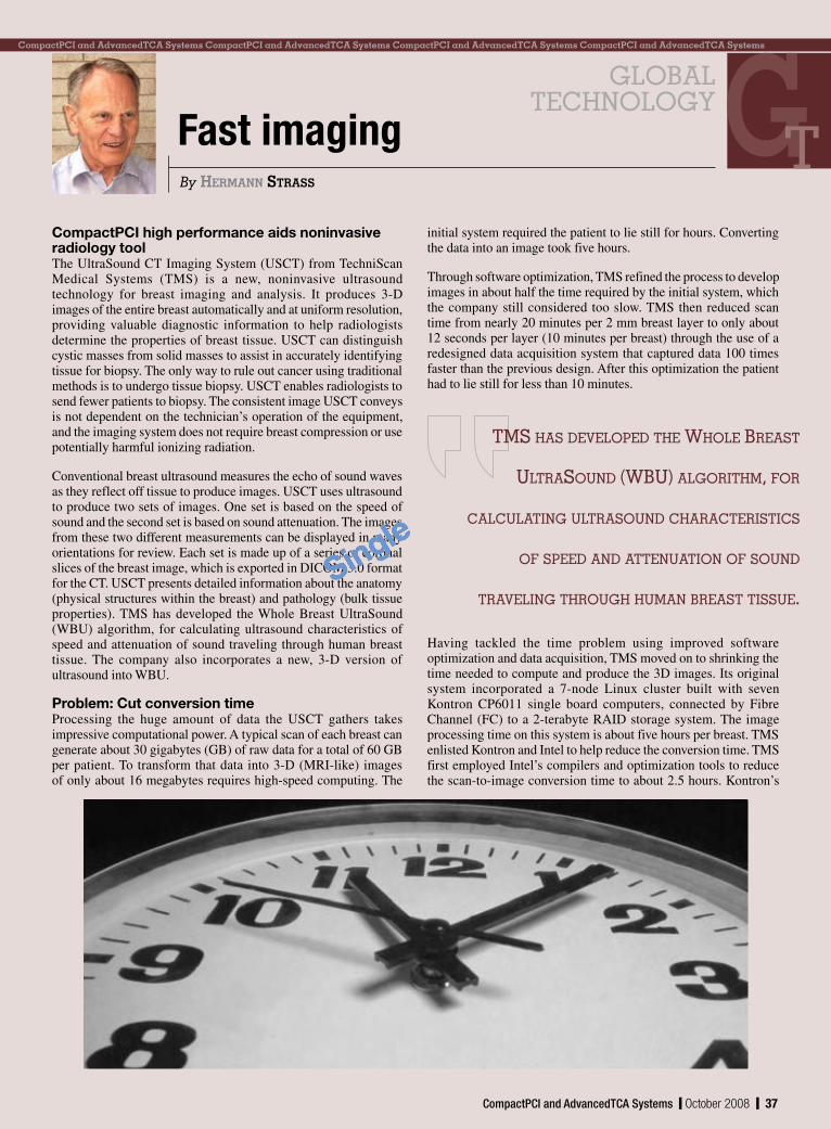
CompactPCI high performance aids noninvasive radiology toolThe UltraSound CT Imaging System (USCT) from TechniScan Medical Systems (TMS) is a new, noninvasive ultrasound technology for breast imaging and analysis. It produces 3-D images of the entire breast automatically and at uniform resolution, providing valuable diagnostic information to help radiologists determine the properties of breast tissue. USCT can distinguish cystic masses from solid masses to assist in accurately identifying tissue for biopsy. The only way to rule out cancer using traditional methods is to undergo tissue biopsy. USCT enables radiologists to send fewer patients to biopsy. The consistent image USCT conveys is not dependent on the technician’s operation of the equipment, and the imaging system does not require breast compression or use potentially harmful ionizing radiation.
Conventional breast ultrasound measures the echo of sound waves as they reflect off tissue to produce images. USCT uses ultrasound to produce two sets of images. One set is based on the speed of sound and the second set is based on sound attenuation. The images from these two different measurements can be displayed in many orientations for review. Each set is made up of a series of coronal slices of the breast image, which is exported in DICOM 3.0 format for the CT. USCT presents detailed information about the anatomy (physical structures within the breast) and pathology (bulk tissue properties). TMS has developed the Whole Breast UltraSound (WBU) algorithm, for calculating ultrasound characteristics of speed and attenuation of sound traveling through human breast tissue. The company also incorporates a new, 3-D version of ultrasound into WBU.
Problem: Cut conversion timeProcessing the huge amount of data the USCT gathers takes impressive computational power. A typical scan of each breast can generate about 30 gigabytes (GB) of raw data for a total of 60 GB per patient. To transform that data into 3-D (MRI-like) images of only about 16 megabytes requires high-speed computing. The
initial system required the patient to lie still for hours. Converting the data into an image took five hours.
Through software optimization, TMS refined the process to develop images in about half the time required by the initial system, which the company still considered too slow. TMS then reduced scan time from nearly 20 minutes per 2 mm breast layer to only about 12 seconds per layer (10 minutes per breast) through the use of a redesigned data acquisition system that captured data 100 times faster than the previous design. After this optimization the patient had to lie still for less than 10 minutes.
Fast imaging
Having tackled the time problem using improved software optimization and data acquisition, TMS moved on to shrinking the time needed to compute and produce the 3D images. Its original system incorporated a 7-node Linux cluster built with seven Kontron CP6011 single board computers, connected by Fibre Channel (FC) to a 2-terabyte RAID storage system. The image processing time on this system is about five hours per breast. TMS enlisted Kontron and Intel to help reduce the conversion time. TMS first employed Intel’s compilers and optimization tools to reduce the scan-to-image conversion time to about 2.5 hours. Kontron’s
TMS hAS DEvElOpED ThE WhOlE BREAST
UlTRASOUND (WBU) AlgORIThM, FOR
CAlCUlATINg UlTRASOUND ChARACTERISTICS
OF SpEED AND ATTENUATION OF SOUND
TRAvElINg ThROUgh hUMAN BREAST TISSUE.
glOBAlTEChNOlOgY
Single

38 y October 2008 y CompactPCI and AdvancedTCA Systems
32 ACT/Technico – 3U CPCI Solutions 7 Annapolis Micro Systems, Inc. – WILDSTAR 526 BittWare, Inc. – Reconfigurable22 Concurrent Technologies, Inc. – x86 Processor Boards39 Data Device Corp. (DDC) – First AMC with 155336 ELMA Electronic – Climb Above with Bustronic 30 Emerson Network Power Embedded Computing – To you, the advantages are clear11 Excalibur Systems, Inc. – Ready for the unexpected? 5 GE Fanuc Intelligent Platforms, Inc. – MicroTCA 6 HARTING Technology Group – AdvancedMC Plug21 Interface Concept – Trust a World-Wide Expert14 Kontron – Flexible17 LCR Electronics – Engineered for Your Application40 Linear Technology Corporation – Reliable Power for AdvancedTCA35 N.A.T. GmbH – Innovation in Communication 3 National Instruments – The Choice for Test Management 27 One Stop Systems Inc. – PCIe over Cable19 Performance Technologies – First-Class CompactPCI Solution13 Radian Heatsinks – This may keep you cool... 1 RadiSys Corporation – ATCA Worldwide Virtual Tradeshow25 Birtcher a Brand of Pentair Electronic Packaging – When your mission is critical23 Simclar Group – TurboFabric Scalable18 Simon Industries – Conduction-cooled Heat Frames 2 TEWS Technologies LLC – I/O Solutions33 White Electronic Designs – Dream Big 8 Winchester Electronics – Power Connector Solutions16 Xalyo Systems – XS-AMC212 XTech – The XTech Files
Advertising Office30233 Jefferson Avenue St. Clair Shores, MI 48082 Tel: 586-415-6500 n Fax: 586-415-4882
Vice President Marketing & Sales Patrick Hopper [email protected]
Business Manager Karen Layman
Sales GroupDennis Doyle Senior Account Manager [email protected]
Tom Varcie Senior Account Manager [email protected]
Doug Cordier Account Manager [email protected]
Andrea Stabile Advertising/Marketing Coordinator [email protected]
Christine Long E-marketing Manager [email protected]
Regional Sales ManagersErnest Godsey Central and Mountain States [email protected]
Barbara Quinlan Midwest/Southwest [email protected]
Denis Seger Southern California [email protected]
Sydele Starr Northern California [email protected]
Ron Taylor East Coast/Mid Atlantic [email protected]
International SalesDan Aronovic Account Manager – Israel [email protected]
Sam Fan Account Manager – Asia [email protected]
Reprints and PDFsNan Lamade: [email protected]
A D V e r T I S e r I N F o r m AT I o N
Page Advertiser/Ad title
CP6012 single board computer (Figure 1, courtesy Kontron), which uses a T2500 Core Duo processor at 2 GHz with 2 GB of memory and has 14 processing cores, brought conversion time down to less than one hour.
CP6012 features include:
T2500 Core Duo processor64-bit, 66 MHz, hot swap CompactPCI interface (PICMG 2.x)CompactPCI Packet Switching Backplane (PICMG 2.16)Two Gigabit Ethernet interfaces, plus four Gigabit Ethernet interfaces via PCI ExpressUp to 4 GB/400 MHz DDR2 SODIMM RAM (6.4 GBps throughput)XMC or PMC slot for mezzanine cards (ANSI/VITA 42 and IEEE 1386)
The CompactPCI boards from Kontron provide top industrial-grade quality for reliable medical systems at the high performance required for this application. Hot swap and Intelligent Platform Management Interface (IPMI) enable reliable system operation. The Linux-based cluster makes for a scalable, flexible system.
TMS has developed USCT with the continued support of the Governor’s Office of Economic Development (GOED) Centers for Excellence Program in Utah, the National Institute of Health (NIH), and the National Cancer Institute (NCI). TMS started clinical trials at the University of California San Diego in La Jolla, California and at the Mayo Clinic in Rochester, Minnesota in May 2008 for final approval by the FDA.
TMS received top honors in the Medical Device category of the third annual Stoel Rives Utah Innovation Awards. TMS has raised nearly $30 million in equity financing and $4 million in federal funding from the NIH and from the National Cancer Institute (NCI). The Esaote Group (Italy), an international leader in the production of ultrasound and MRI medical imaging technologies, invested $9 million in TMS. TMS and Esaote have entered into an OEM agreement that allows TMS and Esaote to each use its partner’s products in its own designs. The two firms have also executed an exclusive distribution agreement for the European market and are looking at developing a commercial cooperation for the American market.
For more information, contact Hermann at [email protected].
Figure 1
glOBAl TEChNOlOgY
Single