Embed Size (px)
Citation preview
AdvancedTCA Shelf, 14-slot
Service Manual
Product Numbers:11596-10011596-10111596-10211596-103
Revision: R1.1, July 23, 2008Doc-No: 63972-171
Impressum:
Schroff GmbH
D-75334 Straubenhardt, Germany
The details in this manual have been carefully compiled andchecked - supported by certified Quality Management Systemto EN ISO 9001/2000
The company cannot accept any liability for errors or misprints.The company reserves the right to amendments of technicalspecifications due to further development and improvement ofproducts.
Copyright © 2008
All rights and technical modifications reserved.
Rev. Date updated Change
R1.0 November 24, 2006 Initial Release
R1.1 July 23, 2006 Chapter 3.4 added
14-Slot AdvancedTCA Shelf11596-100/-101/-102/-103
Table of Contents1 Safety ................................................................................................................. 1
1.1 Safety Symbols used in this document................................................................ 11.2 General Safety Precautions................................................................................. 11.3 References and Architecture Specifications ........................................................ 21.4 Product Definition ................................................................................................ 21.5 ESD Wrist Strap Terminals.................................................................................. 31.6 Terms and Acronyms........................................................................................... 4
2 Shelf Overview.................................................................................................. 5
3 Shelf Installation ............................................................................................. 103.0.1 Ensuring Overcurrent Protection.......................................................... 103.0.2 Ensuring Proper Airflow ....................................................................... 103.0.3 Creating a Safe Environment............................................................... 10
3.1 Unpacking.......................................................................................................... 113.2 Rack-Mounting................................................................................................... 123.3 Mounting Bracket Swap..................................................................................... 143.4 Additional Rear Fixing Points............................................................................. 153.5 Shelf Ground Connection .................................................................................. 16
3.5.1 Specification for the Shelf Ground connection cable ........................... 163.6 Shelf Power Connection .................................................................................... 173.7 Specification for the power connection cables................................................... 173.8 Installation the power connection cables ........................................................... 183.9 Initial Operation.................................................................................................. 193.10 Logic Ground to Shelf Ground connection......................................................... 20
4 Maintenace ...................................................................................................... 214.1 Accessing the Shelf Management Software ...................................................... 21
4.1.1 Command Line Interface (CLI)............................................................. 214.1.2 Basic CLI Commands .......................................................................... 22
4.2 Telco Alarms...................................................................................................... 234.2.1 Telco Alarm Interface........................................................................... 234.2.2 Telco Alarm LEDs................................................................................ 234.2.3 Alarm Silence Push Button .................................................................. 234.2.4 Alarm Reset ......................................................................................... 23
4.3 Air Filter Replacement ....................................................................................... 244.4 Power Entry Module (PEM) Replacement ......................................................... 25
4.4.1 PEM Fuse Replacement ...................................................................... 284.5 Fan Tray Replacement ...................................................................................... 294.6 Shelf Alarm Display (SAD) Replacement .......................................................... 30
www.a-tca.com / www.schroff.biz I R1.1, July 23, 2008
14-Slot AdvancedTCA Shelf11596-100/-101/-102/-103
4.7 Shelf Alarm Panel (SAP) Replacement ............................................................. 314.8 Chassis Data Module (CDM) Replacement....................................................... 314.9 Shelf Manager Replacement ............................................................................. 334.10 ShMM-500 Replacement ................................................................................... 344.11 Insertion of ATCA Boards .................................................................................. 354.12 Part Numbers..................................................................................................... 36
www.a-tca.com / www.schroff.biz II R1.1, July 23, 2008
14-Slot AdvancedTCA Shelf Safety11596-100/-101/-102/-103
1 SafetyThe intended audience of this Service Manual is system integrators and qualified service personnel.The instructions in this manual primarily describe the installation and maintenance of the 14-Slot ATCA Shelf.When installing racks, electrical wiring and other equipment, you should follow all local, state, federal, or international codes and regulations.
1.1 Safety Symbols used in this document
1.2 General Safety Precautions
• Service personnel must know the necessary electrical safety, wiring and connection practices for installing this equipment in a telecommunication environment.
• Install this equipment only in compliance with local and national electrical codes.
• For additional information about this equipment, see the PICMG 3.0 Specification (www.picmg.com) or the User’s Manual.
Hazardous voltage!This is the electrical hazard symbol. It indicates that there are dangerous voltages inside the Shelf.
Caution!This is the user caution symbol. It indicates a condition where damage of the equipment or injury of the service personnel could occur. To reduce the risk of damage or injury, follow all steps or procedures as instructed.
Danger of electrostatic discharge!The Shelf contains static sensitive devices. To prevent static damage you must wear an ESD wrist strap.
Warning!Voltages over 60 VDC can be present in this equipment. As defined in the PICMG 3.0 Specification, this equipment is intended to be accessed, to be installed and maintained by qualified and trained service personnel only.
www.a-tca.com / www.schroff.biz 1 R1.1, July 23, 2008

14-Slot AdvancedTCA Shelf Safety11596-100/-101/-102/-103
1.3 References and Architecture Specifications
• PICMG® 3.0 AdvancedTCA® Base Specification(www.picmg.com)
• PICMG® Engineering Change Notice ECN 3.0-2.0-00
• User’s Manual for the 11596-10x ATCA Shelves, Doc-No.: 63972-172
1.4 Product Definition
The Schroff 11596-10x is a 13U / 14 Slot Shelf and designed according to AdvancedTCA standards.
• Product Number 11596-100: Dual Star Backplane, bused IPMB
• Product Number 11596-101: Dual Star Backplane, radial IPMB
• Product Number 11596-102: Full Mesh Backplane, bused IPMB
• Product Number 11596-103: Full Mesh Backplane, radial IPMB
The Schroff 11596-10x is designed to work with two redundantSchroff ShMM-ACB-IV Shelf Managers, at least one Shelf Manager is needed for a working System.
• Product Number 21593-375: Shelf Manager with bused IPMB• Product Number 21593-376: Shelf Manager with radial IPMB
www.a-tca.com / www.schroff.biz 2 R1.1, July 23, 2008
14-Slot AdvancedTCA Shelf Safety11596-100/-101/-102/-103
1.5 ESD Wrist Strap Terminals
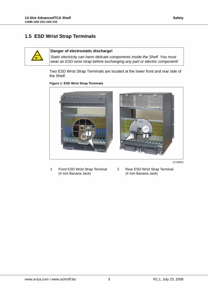
Two ESD Wrist Strap Terminals are located at the lower front and rear side of the Shelf.
Figure 1: ESD Wrist Strap Terminals
Danger of electrostatic discharge!Static electricity can harm delicate components inside the Shelf. You must wear an ESD wrist strap before exchanging any part or electric component!
12706903
1 Front ESD Wrist Strap Terminal(4 mm Banana Jack)
2 Rear ESD Wrist Strap Terminal(4 mm Banana Jack)
www.a-tca.com / www.schroff.biz 3 R1.1, July 23, 2008

14-Slot AdvancedTCA Shelf Safety11596-100/-101/-102/-103
1.6 Terms and Acronyms
Table 1: Terms and Acronyms
Term Definition
ATCA Advanced Telecom Computing Architecture
Backplane Passive circuit board providing the connectors for the front boards. Power distribution, management and auxiliary signal connections are supported
CDM Chassis Data Module
Chassis Enclosure containing subrack, Backplane, boards, cooling devices, PEMs, same as Shelf
ECN Engineering Change Notice
ESD Electrostatic Discharge
ETSI European Telecommunications Standards Institute
FRU Field Replaceable Unit
IPMB Intelligent Platform Management Bus
IPMC Intelligent Platform Management Controller
IPMI Intelligent Platform Management Interface
PCB Printed Circuit Board
PEM Power Entry Module
RTC Real Time Clock
RTM Rear Transition Module
SAP Shelf Alarm Panel
Shelf See Chassis
ShMC Shelf Management Controller, synonymous with Shelf Manager in this document
ShMM Shelf Management Mezzanine Module
VRTN Voltage Return
www.a-tca.com / www.schroff.biz 4 R1.1, July 23, 2008

14-Slot AdvancedTCA Shelf Shelf Overview11596-100/-101/-102/-103
2 Shelf OverviewFigure 2: Shelf Front View
12706961
1 Shelf Alarm Display (SAD) 6 Shelf Alarm Panel (SAP)
2 ATCA 14-Slot Backplane 7 Front Cable Tray
3 Front Card Cage 8 Removable Mounting Bracket
4 Air Filter 9 ESD Wrist Strap Terminal
5 Shelf Manger 1 (left) 10 Shelf Manager 2 (right)
A Transportation Lock
www.a-tca.com / www.schroff.biz 5 R1.1, July 23, 2008

14-Slot AdvancedTCA Shelf Shelf Overview11596-100/-101/-102/-103
Figure 3: Shelf Rear View
12706887
11 Fan Tray #2 16 Fan Tray #0
12 Rear Card Cage 17 Rear Cable Tray
13 ESD Wrist Strap Terminal 18 Shelf Ground Terminal (M6 studs)
14 Power Entry Module B (PEM B) 19 Power Entry Module A (PEM A)
15 Fan Tray #1
www.a-tca.com / www.schroff.biz 6 R1.1, July 23, 2008
14-Slot AdvancedTCA Shelf Shelf Overview11596-100/-101/-102/-103
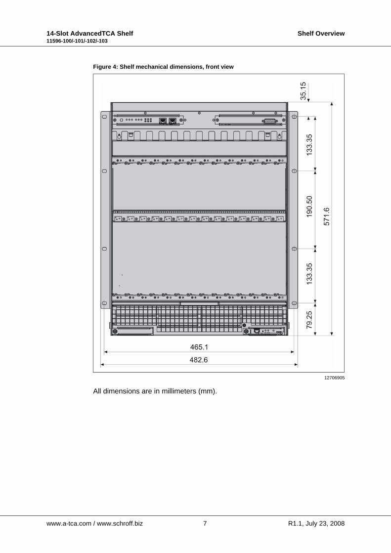
Figure 4: Shelf mechanical dimensions, front view
All dimensions are in millimeters (mm).
12706905
www.a-tca.com / www.schroff.biz 7 R1.1, July 23, 2008
14-Slot AdvancedTCA Shelf Shelf Overview11596-100/-101/-102/-103
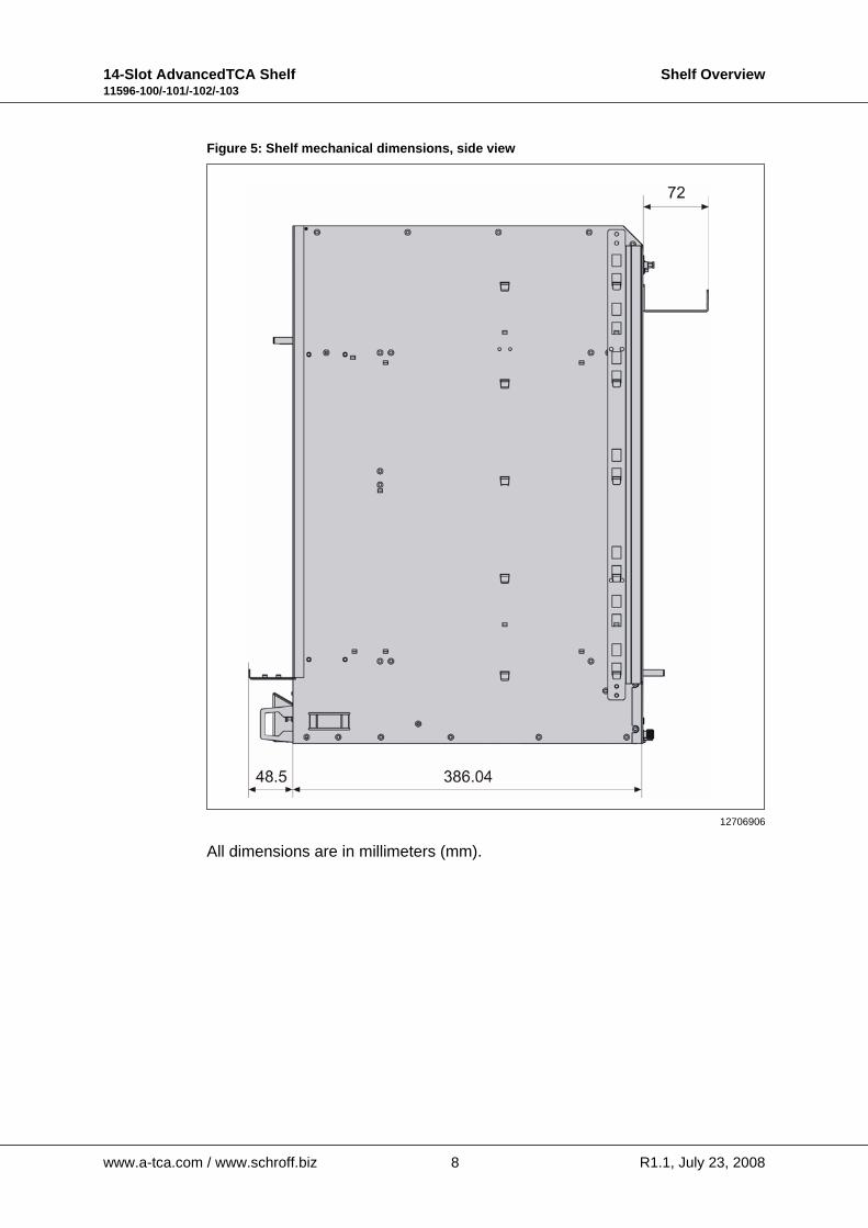
Figure 5: Shelf mechanical dimensions, side view
All dimensions are in millimeters (mm).
12706906
www.a-tca.com / www.schroff.biz 8 R1.1, July 23, 2008
14-Slot AdvancedTCA Shelf Shelf Overview11596-100/-101/-102/-103
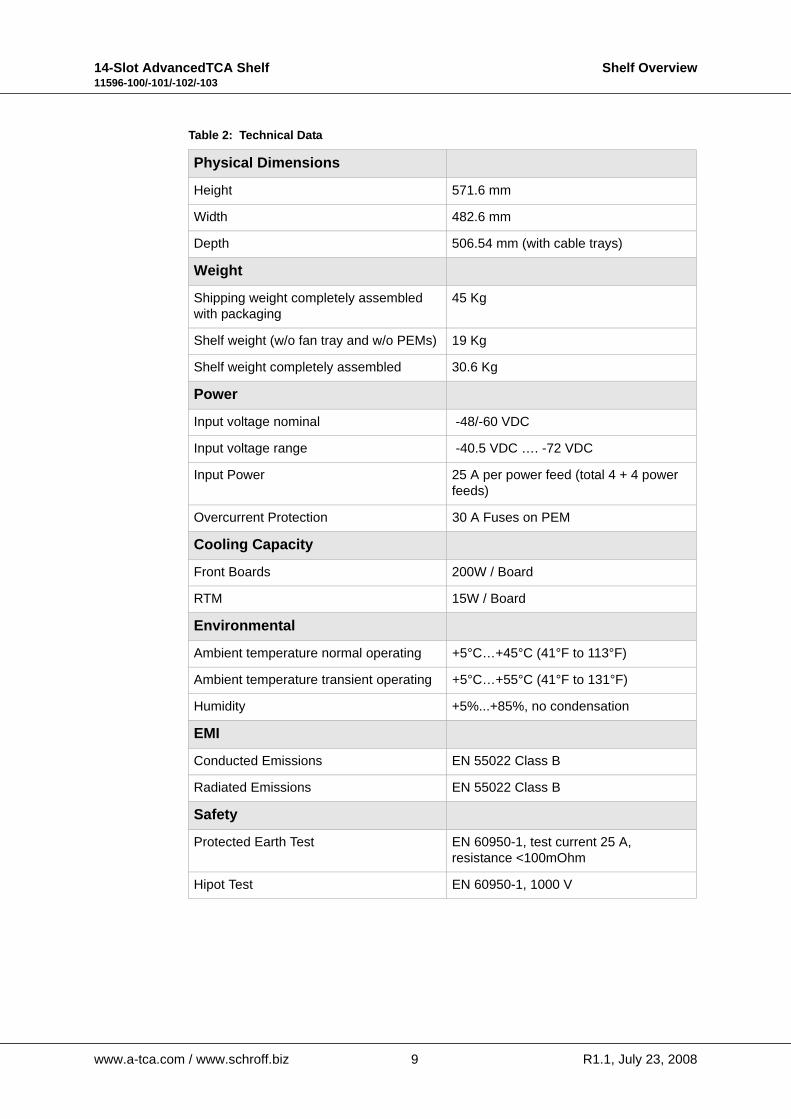
Table 2: Technical Data
Physical Dimensions
Height 571.6 mm
Width 482.6 mm
Depth 506.54 mm (with cable trays)
Weight
Shipping weight completely assembled with packaging
45 Kg
Shelf weight (w/o fan tray and w/o PEMs) 19 Kg
Shelf weight completely assembled 30.6 Kg
Power
Input voltage nominal -48/-60 VDC
Input voltage range -40.5 VDC …. -72 VDC
Input Power 25 A per power feed (total 4 + 4 power feeds)
Overcurrent Protection 30 A Fuses on PEM
Cooling Capacity
Front Boards 200W / Board
RTM 15W / Board
Environmental
Ambient temperature normal operating +5°C…+45°C (41°F to 113°F)
Ambient temperature transient operating +5°C…+55°C (41°F to 131°F)
Humidity +5%...+85%, no condensation
EMI
Conducted Emissions EN 55022 Class B
Radiated Emissions EN 55022 Class B
Safety
Protected Earth Test EN 60950-1, test current 25 A,resistance <100mOhm
Hipot Test EN 60950-1, 1000 V
www.a-tca.com / www.schroff.biz 9 R1.1, July 23, 2008
14-Slot AdvancedTCA Shelf Shelf Installation11596-100/-101/-102/-103
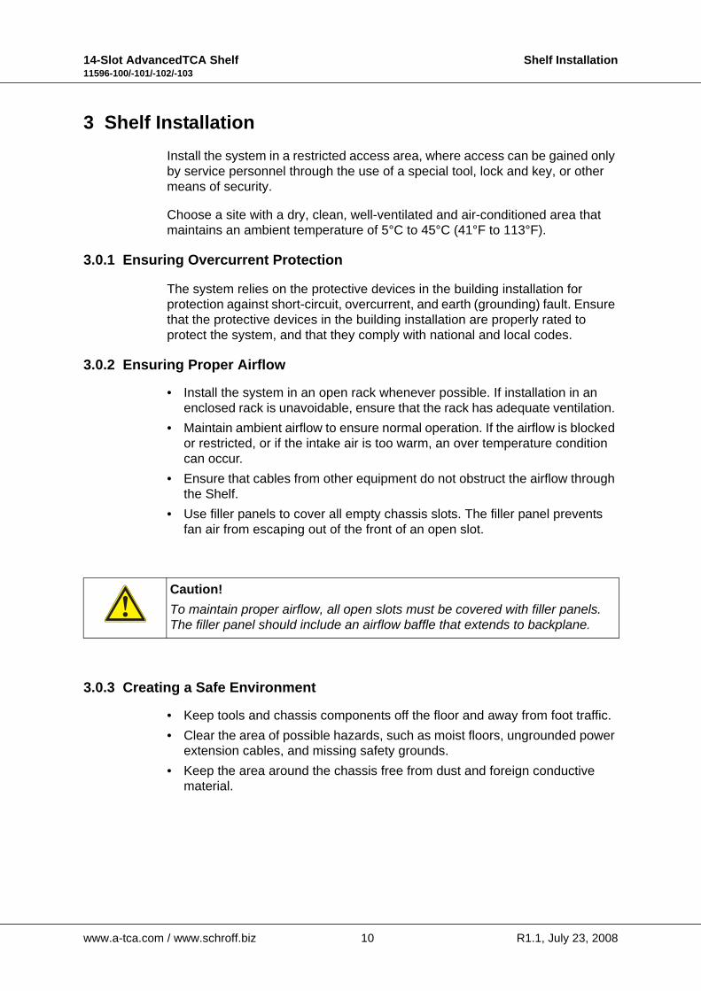
3 Shelf InstallationInstall the system in a restricted access area, where access can be gained only by service personnel through the use of a special tool, lock and key, or other means of security.
Choose a site with a dry, clean, well-ventilated and air-conditioned area that maintains an ambient temperature of 5°C to 45°C (41°F to 113°F).
3.0.1 Ensuring Overcurrent Protection
The system relies on the protective devices in the building installation for protection against short-circuit, overcurrent, and earth (grounding) fault. Ensure that the protective devices in the building installation are properly rated to protect the system, and that they comply with national and local codes.
3.0.2 Ensuring Proper Airflow
• Install the system in an open rack whenever possible. If installation in an enclosed rack is unavoidable, ensure that the rack has adequate ventilation.
• Maintain ambient airflow to ensure normal operation. If the airflow is blocked or restricted, or if the intake air is too warm, an over temperature condition can occur.
• Ensure that cables from other equipment do not obstruct the airflow through the Shelf.
• Use filler panels to cover all empty chassis slots. The filler panel prevents fan air from escaping out of the front of an open slot.
3.0.3 Creating a Safe Environment
• Keep tools and chassis components off the floor and away from foot traffic. • Clear the area of possible hazards, such as moist floors, ungrounded power
extension cables, and missing safety grounds. • Keep the area around the chassis free from dust and foreign conductive
material.
Caution!To maintain proper airflow, all open slots must be covered with filler panels. The filler panel should include an airflow baffle that extends to backplane.
www.a-tca.com / www.schroff.biz 10 R1.1, July 23, 2008
14-Slot AdvancedTCA Shelf Shelf Installation11596-100/-101/-102/-103
3.1 Unpacking
Consider the following when unpacking and storing the Shelf:
• Leave the Shelf packed until it is needed for immediate installation.
• After unpacking the Shelf, save and store the packaging material in case the Shelf must be returned.
• If the packaging is damaged and possible Shelf damage is present, report to the shipper and analyze the damage.
Caution!When opening the shipping carton, use caution to avoid damaging the Shelf.
Danger of electrostatic discharge!The Shelf contains static sensitive devices. While unpacking and handling the Shelf you must wear an ESD wrist strap to prevent static damage.
Caution!Do NOT use the Fan Tray and PEM handles or cable trays as lifting points.
www.a-tca.com / www.schroff.biz 11 R1.1, July 23, 2008
14-Slot AdvancedTCA Shelf Shelf Installation11596-100/-101/-102/-103
3.2 Rack-Mounting
This ATCA 14-slot Shelf can be installed in 19“ equipment racks. The rack must be accessible from the front and rear for equipment installation.
Mounting brackets and cable trays come with the system. Allow sufficient clearance around the rack for system maintenance.
Warning!Do NOT move the Shelf by yourself. Due to the height and weight of the Shelf, at least two persons are needed to accomplish this task. We recommend to use a mechanical lift or remove all hot-swappable equipment for weightreduction.
Warning!Do NOT stack the Shelf on top of any other equipment. If the Shelf falls, it can cause severe bodily injury and damage the equipment.
Caution!Do NOT remove the Transportation Locks (See Fig. 1) before the Shelf is completely fixed in the rack.
Caution!Do NOT use the Fan Tray and PEM handles or cable trays as lifting points.
Danger of electrostatic discharge!The Shelf contains static sensitive devices. While handling the Shelf you must wear an ESD wrist strap to prevent static damage.
www.a-tca.com / www.schroff.biz 12 R1.1, July 23, 2008

14-Slot AdvancedTCA Shelf Shelf Installation11596-100/-101/-102/-103
Mounting Instructions:• Ensure that the rack is constructed to support the weight and dimensions of
the Shelf.• Install any stabilizers that came with your equipment rack before mounting
or servicing the system in the rack.• Load the rack from the bottom to the top, with the heaviest system at the
bottom, avoid uneven mechanical loading of the rack.
Figure 6: Chassis-Support Brackets
.
Caution!Never fix the Shelf only with the mounting brackets! Due to the weight of the Shelf you must use two chassis-support brackets or a rack mount tray.
12706858
3 Chassis-Support Brackets
www.a-tca.com / www.schroff.biz 13 R1.1, July 23, 2008
14-Slot AdvancedTCA Shelf Shelf Installation11596-100/-101/-102/-103
3.3 Mounting Bracket Swap
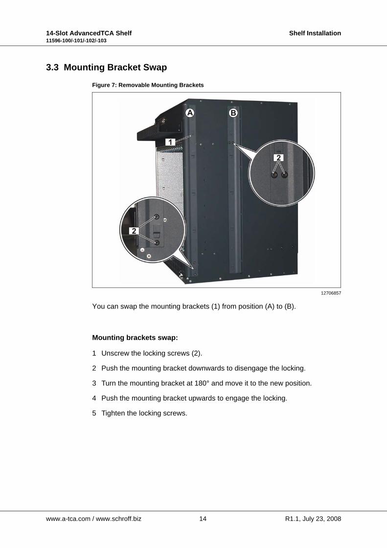
Figure 7: Removable Mounting Brackets
You can swap the mounting brackets (1) from position (A) to (B).
Mounting brackets swap:
1 Unscrew the locking screws (2).
2 Push the mounting bracket downwards to disengage the locking.
3 Turn the mounting bracket at 180° and move it to the new position.
4 Push the mounting bracket upwards to engage the locking.
5 Tighten the locking screws.
12706857
www.a-tca.com / www.schroff.biz 14 R1.1, July 23, 2008
14-Slot AdvancedTCA Shelf Shelf Installation11596-100/-101/-102/-103
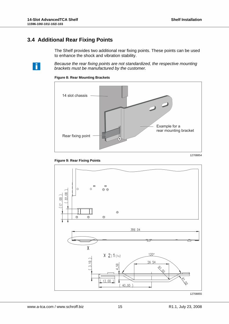
3.4 Additional Rear Fixing Points
The Shelf provides two additional rear fixing points. These points can be used to enhance the shock and vibration stability.
Figure 8: Rear Mounting Brackets
Figure 9: Rear Fixing Points
Because the rear fixing points are not standardized, the respective mounting brackets must be manufactured by the customer.
12708854
12708855
www.a-tca.com / www.schroff.biz 15 R1.1, July 23, 2008

14-Slot AdvancedTCA Shelf Shelf Installation11596-100/-101/-102/-103
3.5 Shelf Ground Connection
The Shelf must be properly grounded via the Shelf Ground Terminal.
The location of the Shelf Ground Terminal is shown in Figure 10.
Figure 10: Shelf ground terminal
Torque for Nuts M6: 5.1 Nm (45 in.-lb.)
3.5.1 Specification for the Shelf Ground connection cable
Required wire size: AWG6
Required terminals: Use only double lug terminals with 45° angle tongue.
Example for terminal:
PANDUIT part no. LCD6-14AH-L, or Thomas&Betts part no. 54205UF
See catalogs at www.panduit.com and www.tnb.com.
Warning!This Shelf is intended to be grounded. Ensure that the Shelf Ground terminals are connected to Protective Earth (PE) of the building.
Danger of electrostatic discharge!Static electricity can harm delicate components inside the Shelf. You must wear an ESD wrist strap before exchanging any part or electric component!
12706892
1 Shelf Ground Terminal 2 PEM A
www.a-tca.com / www.schroff.biz 16 R1.1, July 23, 2008

14-Slot AdvancedTCA Shelf Shelf Installation11596-100/-101/-102/-103
3.6 Shelf Power Connection
3.7 Specification for the power connection cables
Required wire size:Diameter 6 mm² resp. AWG10max. length 2.5 to 3.0 msuitable for 30 A at 50° C ambient temperature.
Required terminals: Use ring terminals for screw M4 or UNC 8-32. Max. outside diameter is 9.3 mm.
Hazardous voltage!Before working ensure that the power is removed from the power connection cables. When the system is powered on, do NOT touch the power terminals!
Warning!Avoid electric overload. To avoid electrical hazard, do not make connections to terminals outside the specified voltage range for that Shelf.
Warning!Ensure that the Shelf is grounded. Ensure that the Shelf Ground terminals are connected to Protective Earth (PE) of the building.
Warning!Although there are fuses in the power entry circuit of the Shelf, the power lines have to be protected on rack level with 30 A breakers.
Warning!Remove jewelry (rings, watches...) before working on equipment that is connected to power lines!
Danger of electrostatic discharge!Static electricity can harm delicate components inside the Shelf. You have to wear ESD wrist straps before exchanging any part or electric component!
The Shelf can be powered using a regular telecommunication power supply of -48/-60 VDC with a VDC return. The specified voltage range is from -40.5 VDC to -72 VDC.The Shelf supports redundant power supplies but the two supplies should be independently powered.
www.a-tca.com / www.schroff.biz 17 R1.1, July 23, 2008
14-Slot AdvancedTCA Shelf Shelf Installation11596-100/-101/-102/-103
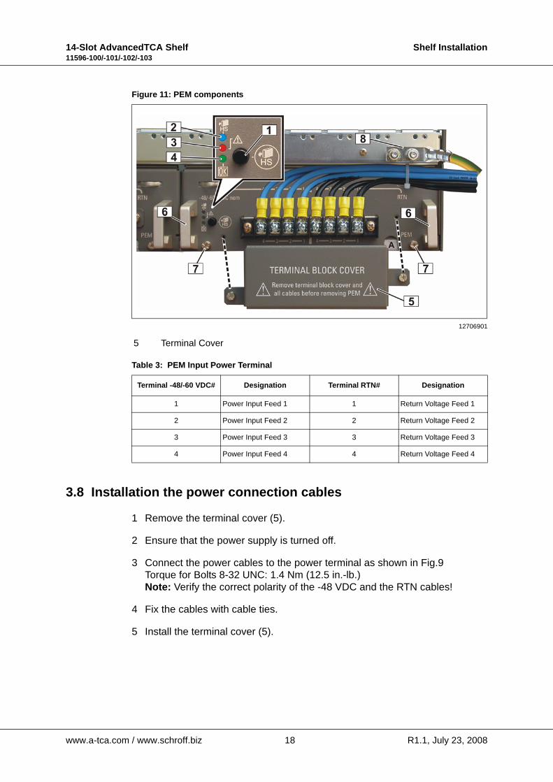
Figure 11: PEM components
Table 3: PEM Input Power Terminal
3.8 Installation the power connection cables
1 Remove the terminal cover (5).
2 Ensure that the power supply is turned off.
3 Connect the power cables to the power terminal as shown in Fig.9Torque for Bolts 8-32 UNC: 1.4 Nm (12.5 in.-lb.)Note: Verify the correct polarity of the -48 VDC and the RTN cables!
4 Fix the cables with cable ties.
5 Install the terminal cover (5).
12706901
5 Terminal Cover
Terminal -48/-60 VDC# Designation Terminal RTN# Designation
1 Power Input Feed 1 1 Return Voltage Feed 1
2 Power Input Feed 2 2 Return Voltage Feed 2
3 Power Input Feed 3 3 Return Voltage Feed 3
4 Power Input Feed 4 4 Return Voltage Feed 4
www.a-tca.com / www.schroff.biz 18 R1.1, July 23, 2008
14-Slot AdvancedTCA Shelf Shelf Installation11596-100/-101/-102/-103
3.9 Initial Operation
Before installing the ATCA boards ensure that there is no transport damage and the system is fully operational.
Apply power to PEM A and PEM B and watch the boot-up process.
Boot-up process:
1 All of the LEDs on the Shelf Alarm Display, the Shelf Manager, the Fan Trays an the PEMs turn on, the fans are spinning with full speed
2 The LEDs on the Shelf Alarm Display with exception of the Fan Tray status LEDs turn off
3 The fans reduce speed up to the initial speed
4 The red LEDs on PEMs, Fan Trays and the Fan Tray status LEDs on Shelf Alarm Display turn off
5 All blue Hot-Swap LEDs blink
6 All blue Hot-Swap LEDs turn off
7 All Status-OK LEDs are green
The Status LED of the active Shelf Manager is solid green, the Status LED of the backup Shelf Manager is blinking.
www.a-tca.com / www.schroff.biz 19 R1.1, July 23, 2008
14-Slot AdvancedTCA Shelf Shelf Installation11596-100/-101/-102/-103
3.10 Logic Ground to Shelf Ground connection
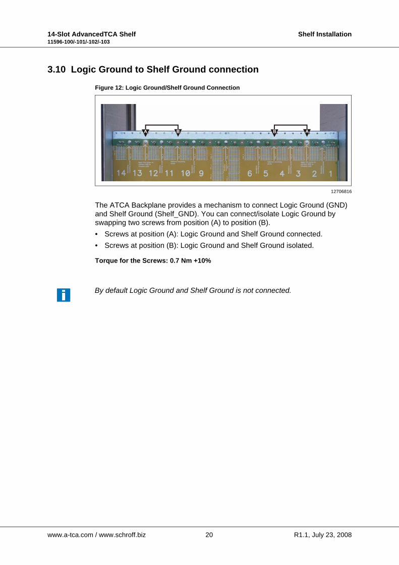
Figure 12: Logic Ground/Shelf Ground Connection
The ATCA Backplane provides a mechanism to connect Logic Ground (GND) and Shelf Ground (Shelf_GND). You can connect/isolate Logic Ground by swapping two screws from position (A) to position (B).• Screws at position (A): Logic Ground and Shelf Ground connected.• Screws at position (B): Logic Ground and Shelf Ground isolated.
Torque for the Screws: 0.7 Nm +10%
12706816
By default Logic Ground and Shelf Ground is not connected.
www.a-tca.com / www.schroff.biz 20 R1.1, July 23, 2008
14-Slot AdvancedTCA Shelf Maintenace11596-100/-101/-102/-103
4 Maintenace
4.1 Accessing the Shelf Management Software
You can access to the Shelf Management software either remotely through ethernet (Tenet, SSH) or by connecting a terminal console directly to the Shelf Manager’s serial console interface (RJ45) on the Shelf Alarm Panel (SAP).
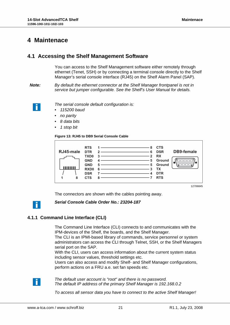
Figure 13: RJ45 to DB9 Serial Console Cable
The connectors are shown with the cables pointing away.
4.1.1 Command Line Interface (CLI)
The Command Line Interface (CLI) connects to and communicates with the IPM-devices of the Shelf, the boards, and the Shelf Manager.The CLI is an IPMI-based library of commands, service personnel or system administrators can access the CLI through Telnet, SSH, or the Shelf Managers serial port on the SAP.With the CLI, users can access information about the current system status including sensor values, threshold settings etc.Users can also access and modify Shelf- and Shelf Manager configurations, perform actions on a FRU a.e. set fan speeds etc.
Note: By default the ethernet connector at the Shelf Manager frontpanel is not inservice but jumper configurable. See the Shelf’s User Manual for details.
The serial console default configuration is:• 115200 baud• no parity• 8 data bits• 1 stop bit
12706845
RJ45-male DB9-female
1
2
3
4
5
6
7
8
RTS
DTR
TXD0
GND
GND
RXD0
DSR
CTS
8
6
2
5
5
3
4
7
CTS
DSR
RX
Ground
Ground
TX
DTR
RTS
5 1
9 6
1 8
Serial Console Cable Order No.: 23204-187
The default user account is “root“ and there is no password.The default IP address of the primary Shelf Manager is 192.168.0.2
To access all sensor data you have to connect to the active Shelf Manager!
www.a-tca.com / www.schroff.biz 21 R1.1, July 23, 2008
14-Slot AdvancedTCA Shelf Maintenace11596-100/-101/-102/-103
4.1.2 Basic CLI Commands
Service personnel can read system information, FRU information and sensor data with the following basic commands. For a full list of all CLI commands refer to the Firmware User Manual.
• Change IP address of the primary Shelf Manager:clia setlanconfig channel ip value
Value represents the IP address in dotted decimal notation.
clia setlanconfig 1 ip 192.168.0.2
• Display the Shelf Managers firmware version:clia version
Info: To get a complete list of all information just type in “version“.
• List all IPM Controllers in a Shelf:clia ipmc
• List all boards in the Shelf:clia board
• List all sensors on a board:clia sensor IPMI-address
• List only sensors which are outside of established thresholds:clia sensor -t
• Get data (value) from a sensor on a board:clia sensordata IPMI-address sensor-number
• Display the FRU information in a board:clia fruinfo IPMI-address FRU-id
• Change the speed for a Fan Tray:clia setfanlevel IPMI-address Fru-id speed
Info: The value for the speed is from 0 to 4.
• Display the contents of the System Event Log (SEL):clia sel
• Clear the System Event Log (SEL):clia sel clear
www.a-tca.com / www.schroff.biz 22 R1.1, July 23, 2008
14-Slot AdvancedTCA Shelf Maintenace11596-100/-101/-102/-103
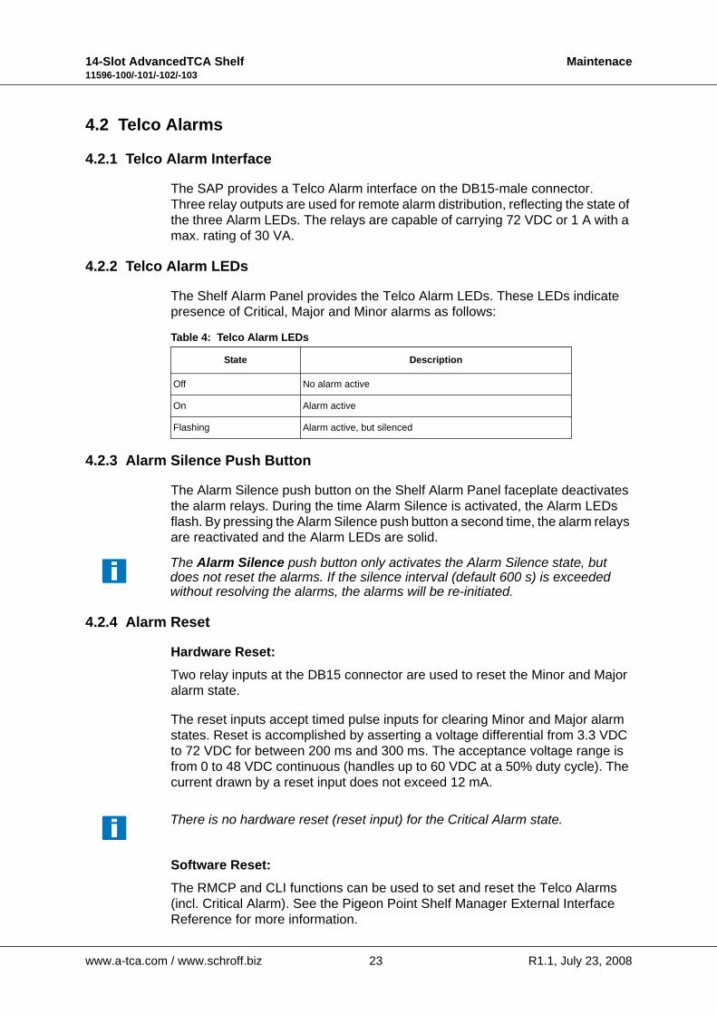
4.2 Telco Alarms
4.2.1 Telco Alarm Interface
The SAP provides a Telco Alarm interface on the DB15-male connector.Three relay outputs are used for remote alarm distribution, reflecting the state of the three Alarm LEDs. The relays are capable of carrying 72 VDC or 1 A with a max. rating of 30 VA.
4.2.2 Telco Alarm LEDs
The Shelf Alarm Panel provides the Telco Alarm LEDs. These LEDs indicate presence of Critical, Major and Minor alarms as follows:
Table 4: Telco Alarm LEDs
4.2.3 Alarm Silence Push Button
The Alarm Silence push button on the Shelf Alarm Panel faceplate deactivates the alarm relays. During the time Alarm Silence is activated, the Alarm LEDs flash. By pressing the Alarm Silence push button a second time, the alarm relays are reactivated and the Alarm LEDs are solid.
4.2.4 Alarm Reset
Hardware Reset:Two relay inputs at the DB15 connector are used to reset the Minor and Major alarm state.
The reset inputs accept timed pulse inputs for clearing Minor and Major alarm states. Reset is accomplished by asserting a voltage differential from 3.3 VDC to 72 VDC for between 200 ms and 300 ms. The acceptance voltage range is from 0 to 48 VDC continuous (handles up to 60 VDC at a 50% duty cycle). The current drawn by a reset input does not exceed 12 mA.
Software Reset:The RMCP and CLI functions can be used to set and reset the Telco Alarms (incl. Critical Alarm). See the Pigeon Point Shelf Manager External Interface Reference for more information.
State Description
Off No alarm active
On Alarm active
Flashing Alarm active, but silenced
The Alarm Silence push button only activates the Alarm Silence state, but does not reset the alarms. If the silence interval (default 600 s) is exceeded without resolving the alarms, the alarms will be re-initiated.
There is no hardware reset (reset input) for the Critical Alarm state.
www.a-tca.com / www.schroff.biz 23 R1.1, July 23, 2008
14-Slot AdvancedTCA Shelf Maintenace11596-100/-101/-102/-103
4.3 Air Filter Replacement
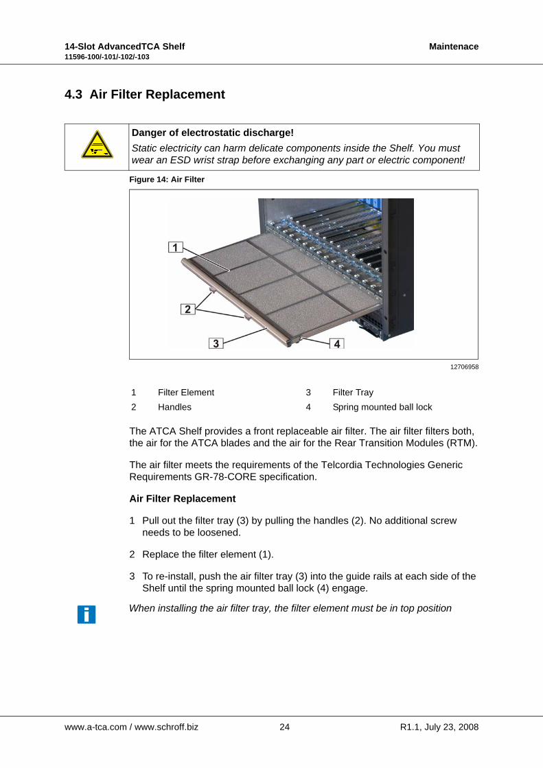
Figure 14: Air Filter
The ATCA Shelf provides a front replaceable air filter. The air filter filters both, the air for the ATCA blades and the air for the Rear Transition Modules (RTM).
The air filter meets the requirements of the Telcordia Technologies Generic Requirements GR-78-CORE specification.
Air Filter Replacement
1 Pull out the filter tray (3) by pulling the handles (2). No additional screw needs to be loosened.
2 Replace the filter element (1).
3 To re-install, push the air filter tray (3) into the guide rails at each side of the Shelf until the spring mounted ball lock (4) engage.
Danger of electrostatic discharge!Static electricity can harm delicate components inside the Shelf. You must wear an ESD wrist strap before exchanging any part or electric component!
12706958
1 Filter Element 3 Filter Tray2 Handles 4 Spring mounted ball lock
When installing the air filter tray, the filter element must be in top position
www.a-tca.com / www.schroff.biz 24 R1.1, July 23, 2008

14-Slot AdvancedTCA Shelf Maintenace11596-100/-101/-102/-103
4.4 Power Entry Module (PEM) Replacement
Under normal operation, the green OK LED on the PEM is lit, indicating that there is supply voltage on all power feeds and the PEM is fully functional.
When the red Failure LED lights up, there is either a supply voltage missing, a fuse blown or the PEM not working. Before replacing a PEM, check if all power feeds are present at the PEM connector.
Hazardous voltage!Before disconnecting the power cables ensure that the power is removed from the power cables. When the system is powered on, do NOT touch the power terminals!
Warning!This Shelf is intended to be grounded. Ensure that the Shelf Ground terminals are connected to Protective Earth (PE) of the building.
Warning!Although there are fuses in the power entry circuit of the Shelf, the power lines have to be protected on rack level with 30 A breakers.
Warning!Remove jewelry (rings, watches...) before working on equipment that is connected to power lines!
Warning!Before removing a PEM, make sure that the Power Segments of the other PEM are fully functional.
Danger of electrostatic discharge!Static electricity can harm delicate components inside the Shelf. You must wear an ESD wrist strap before exchanging any part or electric component!
Caution!To maintain proper airflow, do not leave a PEM slot open.
www.a-tca.com / www.schroff.biz 25 R1.1, July 23, 2008
14-Slot AdvancedTCA Shelf Maintenace11596-100/-101/-102/-103
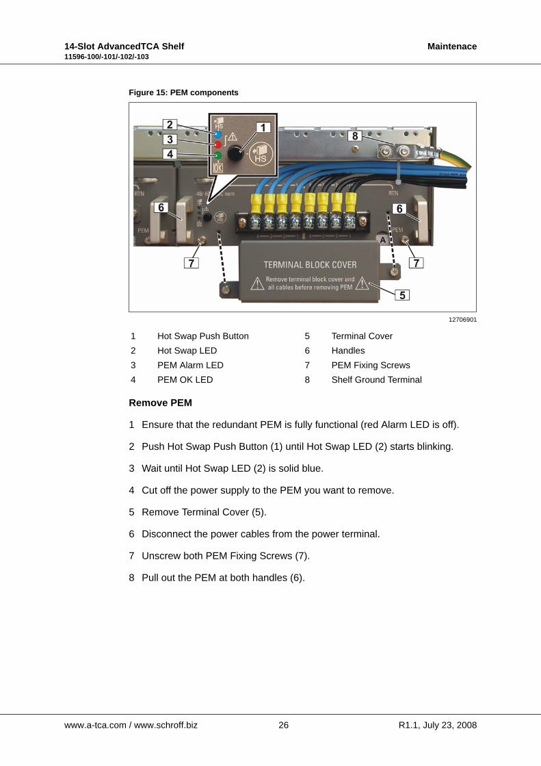
Figure 15: PEM components
Remove PEM
1 Ensure that the redundant PEM is fully functional (red Alarm LED is off).
2 Push Hot Swap Push Button (1) until Hot Swap LED (2) starts blinking.
3 Wait until Hot Swap LED (2) is solid blue.
4 Cut off the power supply to the PEM you want to remove.
5 Remove Terminal Cover (5).
6 Disconnect the power cables from the power terminal.
7 Unscrew both PEM Fixing Screws (7).
8 Pull out the PEM at both handles (6).
12706901
1 Hot Swap Push Button 5 Terminal Cover2 Hot Swap LED 6 Handles3 PEM Alarm LED 7 PEM Fixing Screws4 PEM OK LED 8 Shelf Ground Terminal
www.a-tca.com / www.schroff.biz 26 R1.1, July 23, 2008
14-Slot AdvancedTCA Shelf Maintenace11596-100/-101/-102/-103
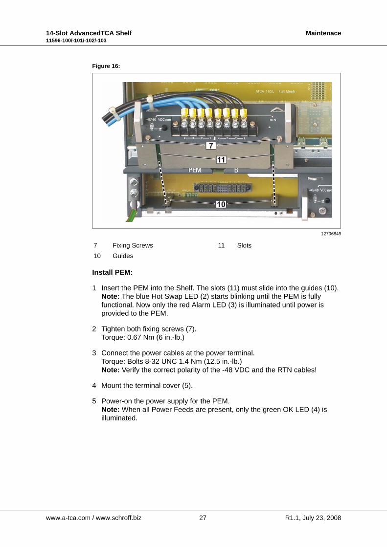
Figure 16:
Install PEM:
1 Insert the PEM into the Shelf. The slots (11) must slide into the guides (10).Note: The blue Hot Swap LED (2) starts blinking until the PEM is fully functional. Now only the red Alarm LED (3) is illuminated until power isprovided to the PEM.
2 Tighten both fixing screws (7).Torque: 0.67 Nm (6 in.-lb.)
3 Connect the power cables at the power terminal.Torque: Bolts 8-32 UNC 1.4 Nm (12.5 in.-lb.)Note: Verify the correct polarity of the -48 VDC and the RTN cables!
4 Mount the terminal cover (5).
5 Power-on the power supply for the PEM.Note: When all Power Feeds are present, only the green OK LED (4) is illuminated.
12706849
7 Fixing Screws 11 Slots10 Guides
www.a-tca.com / www.schroff.biz 27 R1.1, July 23, 2008
14-Slot AdvancedTCA Shelf Maintenace11596-100/-101/-102/-103
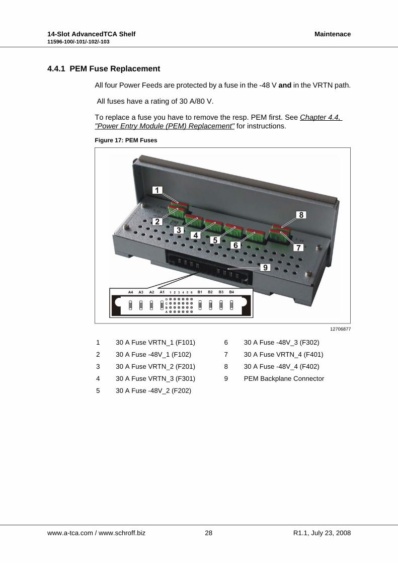
4.4.1 PEM Fuse Replacement
All four Power Feeds are protected by a fuse in the -48 V and in the VRTN path.
All fuses have a rating of 30 A/80 V.
To replace a fuse you have to remove the resp. PEM first. See Chapter 4.4, "Power Entry Module (PEM) Replacement" for instructions.
Figure 17: PEM Fuses
12706877
1 30 A Fuse VRTN_1 (F101) 6 30 A Fuse -48V_3 (F302)
2 30 A Fuse -48V_1 (F102) 7 30 A Fuse VRTN_4 (F401)
3 30 A Fuse VRTN_2 (F201) 8 30 A Fuse -48V_4 (F402)
4 30 A Fuse VRTN_3 (F301) 9 PEM Backplane Connector
5 30 A Fuse -48V_2 (F202)
www.a-tca.com / www.schroff.biz 28 R1.1, July 23, 2008
14-Slot AdvancedTCA Shelf Maintenace11596-100/-101/-102/-103
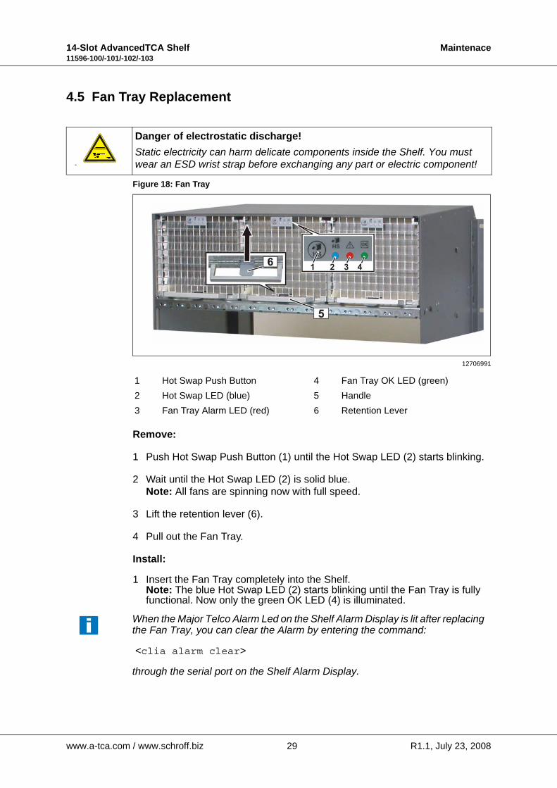
4.5 Fan Tray Replacement
Figure 18: Fan Tray
Remove:
1 Push Hot Swap Push Button (1) until the Hot Swap LED (2) starts blinking.
2 Wait until the Hot Swap LED (2) is solid blue.Note: All fans are spinning now with full speed.
3 Lift the retention lever (6).
4 Pull out the Fan Tray.
Install:
1 Insert the Fan Tray completely into the Shelf.Note: The blue Hot Swap LED (2) starts blinking until the Fan Tray is fully functional. Now only the green OK LED (4) is illuminated.
an
Danger of electrostatic discharge!Static electricity can harm delicate components inside the Shelf. You must wear an ESD wrist strap before exchanging any part or electric component!
12706991
1 Hot Swap Push Button 4 Fan Tray OK LED (green)2 Hot Swap LED (blue) 5 Handle3 Fan Tray Alarm LED (red) 6 Retention Lever
When the Major Telco Alarm Led on the Shelf Alarm Display is lit after replacing the Fan Tray, you can clear the Alarm by entering the command:
<clia alarm clear>
through the serial port on the Shelf Alarm Display.
www.a-tca.com / www.schroff.biz 29 R1.1, July 23, 2008
14-Slot AdvancedTCA Shelf Maintenace11596-100/-101/-102/-103
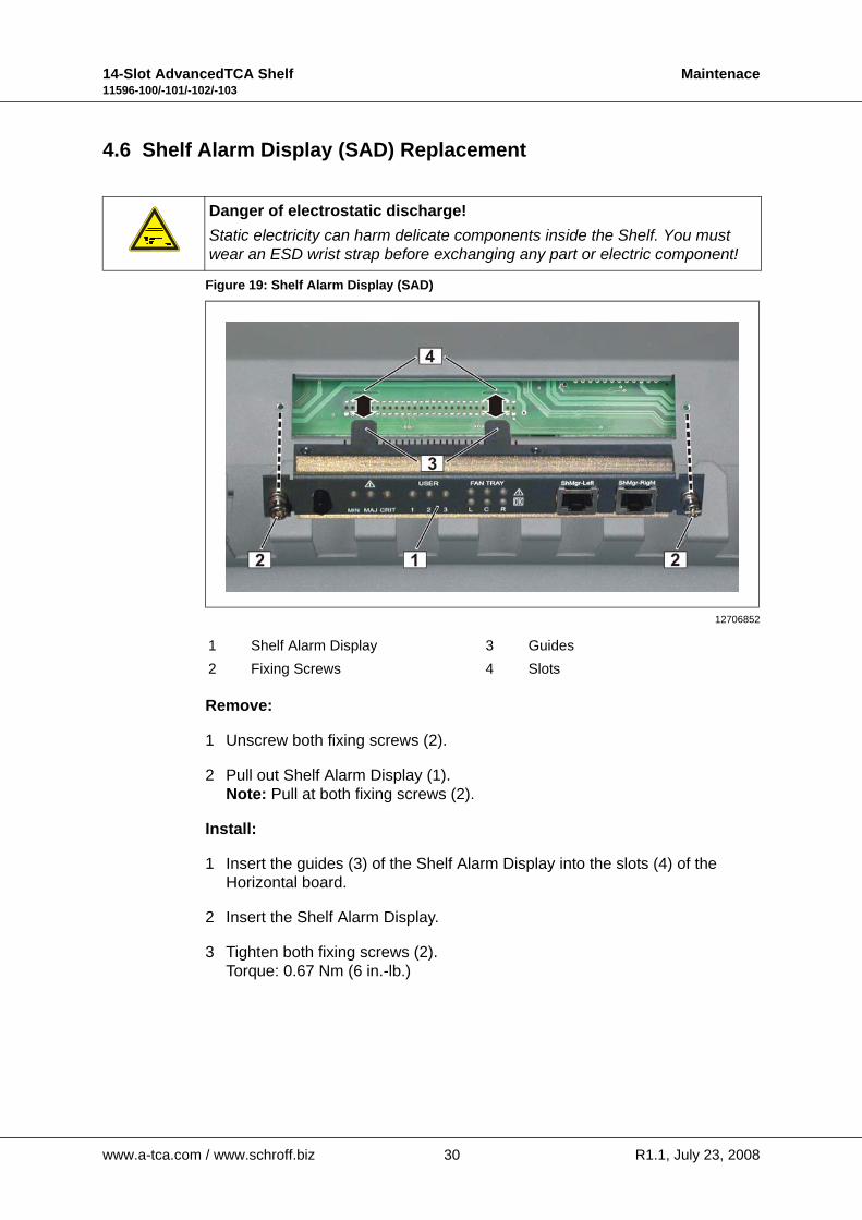
4.6 Shelf Alarm Display (SAD) Replacement
Figure 19: Shelf Alarm Display (SAD)
Remove:
1 Unscrew both fixing screws (2).
2 Pull out Shelf Alarm Display (1).Note: Pull at both fixing screws (2).
Install:
1 Insert the guides (3) of the Shelf Alarm Display into the slots (4) of the Horizontal board.
2 Insert the Shelf Alarm Display.
3 Tighten both fixing screws (2).Torque: 0.67 Nm (6 in.-lb.)
Danger of electrostatic discharge!Static electricity can harm delicate components inside the Shelf. You must wear an ESD wrist strap before exchanging any part or electric component!
12706852
1 Shelf Alarm Display 3 Guides2 Fixing Screws 4 Slots
www.a-tca.com / www.schroff.biz 30 R1.1, July 23, 2008

14-Slot AdvancedTCA Shelf Maintenace11596-100/-101/-102/-103
4.7 Shelf Alarm Panel (SAP) Replacement
For instructions see Chapter 4.6, "Shelf Alarm Display (SAD) Replacement".
Figure 20: Shelf Alarm Panel (SAP)
4.8 Chassis Data Module (CDM) Replacement
The Chassis Data Modules (CDMs) are located on the Backplane behind the Power Entry Modules (PEMs). To replace a CDM you have to remove the resp. PEM first.• CDM 1 is located behind PEM A.• CDM 2 is located behind PEM B.
12706962
Warning!Before removing a PEM, ensure that the Power Segments of the other PEM are fully functional.
Hazardous voltage!Before working ensure that the power is removed from the power connectioncables. When the system is powered on, do NOT touch the power terminals!
Warning!This Shelf is intended to be grounded. Ensure that the Shelf Ground terminals are connected to Protective Earth (PE) of the building.
Warning!Remove jewelry (rings, watches...) before working on equipment that is connected to power lines!
Danger of electrostatic discharge!Static electricity can harm delicate components inside the Shelf. You must wear an ESD wrist strap before exchanging any part or electric component!
www.a-tca.com / www.schroff.biz 31 R1.1, July 23, 2008
14-Slot AdvancedTCA Shelf Maintenace11596-100/-101/-102/-103
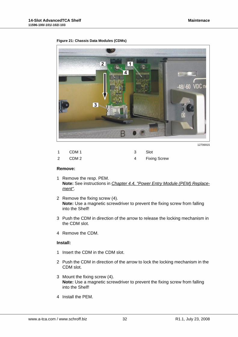
Figure 21: Chassis Data Modules (CDMs) 1
Remove:
1 Remove the resp. PEM.Note: See instructions in Chapter 4.4, "Power Entry Module (PEM) Replace-ment".
2 Remove the fixing screw (4).Note: Use a magnetic screwdriver to prevent the fixing screw from falling into the Shelf!
3 Push the CDM in direction of the arrow to release the locking mechanism in the CDM slot.
4 Remove the CDM.
Install:
1 Insert the CDM in the CDM slot.
2 Push the CDM in direction of the arrow to lock the locking mechanism in the CDM slot.
3 Mount the fixing screw (4).Note: Use a magnetic screwdriver to prevent the fixing screw from falling into the Shelf!
4 Install the PEM.
12706915
1 CDM 1 3 Slot2 CDM 2 4 Fixing Screw
www.a-tca.com / www.schroff.biz 32 R1.1, July 23, 2008
14-Slot AdvancedTCA Shelf Maintenace11596-100/-101/-102/-103
4.9 Shelf Manager Replacement
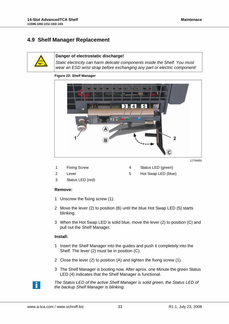
Figure 22: Shelf Manager
Remove:
1 Unscrew the fixing screw (1).
2 Move the lever (2) to position (B) until the blue Hot Swap LED (5) starts blinking.
3 When the Hot Swap LED is solid blue, move the lever (2) to position (C) and pull out the Shelf Manager.
Install:
1 Insert the Shelf Manager into the guides and push it completely into the Shelf. The lever (2) must be in position (C).
2 Close the lever (2) to position (A) and tighten the fixing screw (1).
3 The Shelf Manager is booting now. After aprox. one Minute the green Status LED (4) indicates that the Shelf Manager is functional.
Danger of electrostatic discharge!Static electricity can harm delicate components inside the Shelf. You must wear an ESD wrist strap before exchanging any part or electric component!
12706850
1 Fixing Screw 4 Status LED (green)2 Lever 5 Hot Swap LED (blue)3 Status LED (red)
The Status LED of the active Shelf Manager is solid green, the Status LED of the backup Shelf Manager is blinking.
www.a-tca.com / www.schroff.biz 33 R1.1, July 23, 2008
14-Slot AdvancedTCA Shelf Maintenace11596-100/-101/-102/-103
4.10 ShMM-500 Replacement
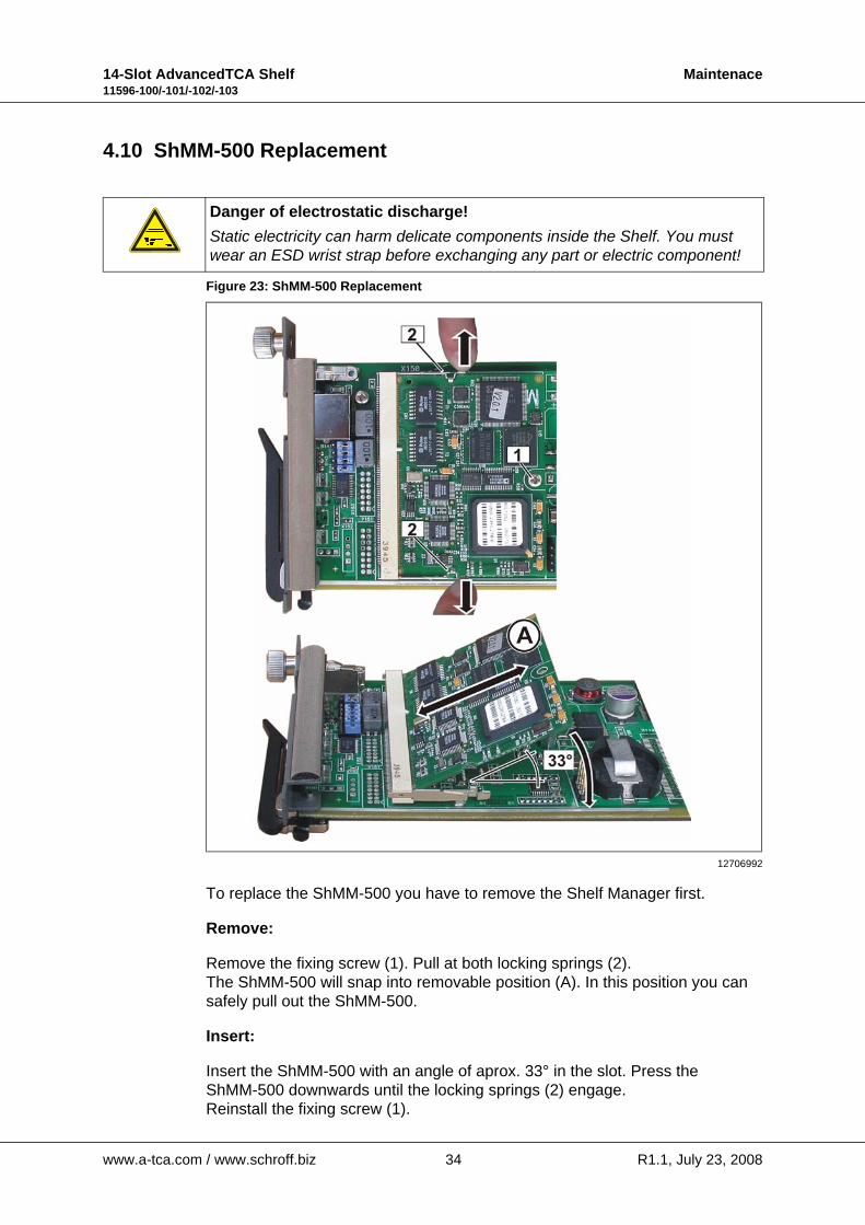
Figure 23: ShMM-500 Replacement
To replace the ShMM-500 you have to remove the Shelf Manager first.
Remove:
Remove the fixing screw (1). Pull at both locking springs (2).The ShMM-500 will snap into removable position (A). In this position you can safely pull out the ShMM-500.
Insert:
Insert the ShMM-500 with an angle of aprox. 33° in the slot. Press the ShMM-500 downwards until the locking springs (2) engage.Reinstall the fixing screw (1).
Danger of electrostatic discharge!Static electricity can harm delicate components inside the Shelf. You must wear an ESD wrist strap before exchanging any part or electric component!
12706992
www.a-tca.com / www.schroff.biz 34 R1.1, July 23, 2008
14-Slot AdvancedTCA Shelf Maintenace11596-100/-101/-102/-103
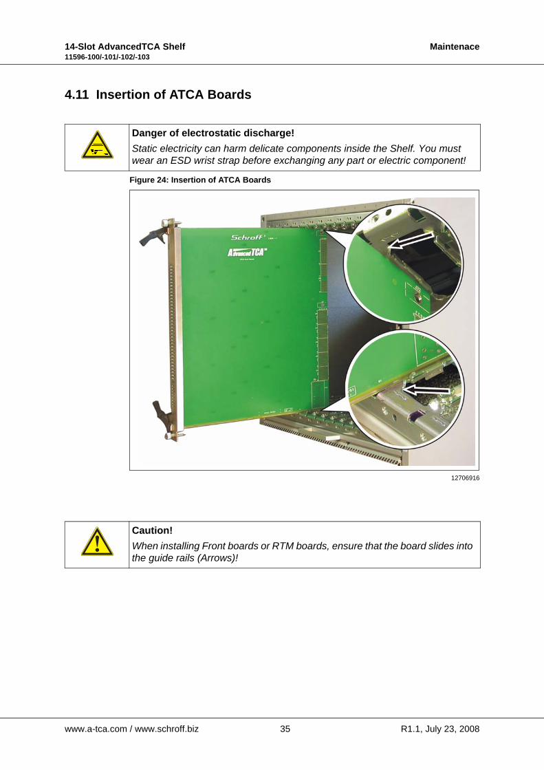
4.11 Insertion of ATCA Boards
Figure 24: Insertion of ATCA Boards
Danger of electrostatic discharge!Static electricity can harm delicate components inside the Shelf. You must wear an ESD wrist strap before exchanging any part or electric component!
12706916
Caution!When installing Front boards or RTM boards, ensure that the board slides into the guide rails (Arrows)!
www.a-tca.com / www.schroff.biz 35 R1.1, July 23, 2008
14-Slot AdvancedTCA Shelf Maintenace11596-100/-101/-102/-103
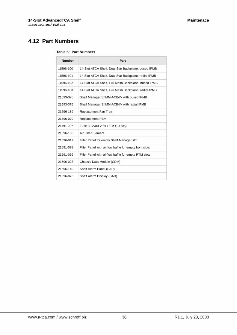
4.12 Part Numbers
Table 5: Part Numbers
Number Part
11596-100 14-Slot ATCA Shelf, Dual Star Backplane, bused IPMB
11596-101 14-Slot ATCA Shelf, Dual Star Backplane, radial IPMB
11596-102 14-Slot ATCA Shelf, Full Mesh Backplane, bused IPMB
11596-103 14-Slot ATCA Shelf, Full Mesh Backplane, radial IPMB
21593-375 Shelf Manager ShMM-ACB-IV with bused IPMB
21593-376 Shelf Manager ShMM-ACB-IV with radial IPMB
21596-139 Replacement Fan Tray
21596-020 Replacement PEM
21191-207 Fuse 30 A/80 V for PEM (10 pcs)
21596-138 Air Filter Element
21596-012 Filler Panel for empty Shelf Manager slot
21591-079 Filler Panel with airflow baffle for empty front slots
21591-099 Filler Panel with airflow baffle for empty RTM slots
21596-023 Chassis Data Module (CDM)
21596-140 Shelf Alarm Panel (SAP)
21596-026 Shelf Alarm Display (SAD)
www.a-tca.com / www.schroff.biz 36 R1.1, July 23, 2008


SCHROFF GMBH www.schroff.bizwww.a-tca.com
Langenalberstr. 96-100 Tel.: + 49 (0) 7082 794-0 Fax: +49 (0) 7082 794-200D-75334 Straubenhardt