Embed Size (px)
Citation preview
Int. J. Vehicle Design, Vol. 35, No. 3, 2004 167
Copyright © 2004 Inderscience Enterprises Ltd.
Combined maximization of interior comfort and frontal crashworthiness in preliminary vehicle design
K. Hamza, I. Hossoy, J.F. Reyes-Luna and P.Y. Papalambros* Department of Mechanical Engineering, University of Michigan, Ann Arbor, MI 48109, USA E-mail: [email protected] *Corresponding author
Abstract: Designing for improved interior comfort and crashworthiness is an important but competing objective in vehicle development. These objectives are linked by common design decisions on allocating a fixed total amount of space, and so they should be addressed together. Such combined optimisation is hindered by the large computational effort required for crash analysis using full-scale vehicle models and by the lack of adequate interior comfort models. In this paper, a driver and rear passenger seating comfort model is combined with a modest but adequate frontal crashworthiness model into an overall system optimisation problem. Solution of the combined problem allows a quantitative investigation into design tradeoffs between comfort and safety. The results suggest that combined optimisation can lead to superior vehicle designs and they motivate more detailed studies with models of increased fidelity.
Keywords: design optimisation; interior vehicle comfort; frontal crashworthiness; genetic algorithms.
Reference to this paper should be made as follows: Hamza, K., Hossoy, I., Reyes-Luna, J.F. and Papalambros, P.Y. (2004) ‘Combined maximization of interior comfort and frontal crashworthiness in preliminary vehicle design’, Int. J. Vehicle Design, Vol. 35, No. 3, pp.167–185.
Biographical notes: Karim Hamza completed his BSc (1998) and MS (2001) in Mechanical Engineering at Cairo University, Egypt, where he worked as Teaching and Research Assistant (1998–2001). He is now a graduate student Research Assistant at the University of Michigan, Ann Arbor, USA. His research interests include design optimisation using evolutionary and heuristic methods, structural and mechanical design.
Ilkin Hossoy completed her BSc (1999) and MS (2001) in Textile Engineering in Istanbul Technical University (ITU), Turkey, where she worked as Research Assistant (1999–2001). She is now a graduate student Research Assistant at the University of Michigan, Ann Arbor, USA. Her research interests are quantification of customer preferences in engineering design, interdisciplinary design optimisation and interface of psychology with engineering.
Juan Francisco Reyes Luna completed his MS in Mechanical Engineering at the University of Michigan, Ann Arbor. He is now Assistant Professor at Universidad de las Americas-Puebla, Mexico, and Research Analyst Engineer at GE Aircraft Engines (CIAT, Mexico). His main research fields are topological optimisation, probabilistic design techniques and evolutionary computation in mechanical design.

168 K. Hamza et al.
Panos Y. Papalambros is the Donald C. Graham Professor of Engineering and a Professor of Mechanical Engineering at the University of Michigan. He holds a diploma from the National Technical University of Athens and MS and PhD degrees from Stanford University. His research interests include design methods and systems optimisation, with applications to product design and automotive systems. He is coauthor of the textbook Principles of Optimal Design: Modeling and Computation (1988, 2000). He serves on the editorial boards of the journals Artificial Intelligence in Engineering Design and Manufacturing, Engineering Design, Engineering Optimization, Computer-Integrated Engineering, Structural and Multidisciplinary Optimization, and the International Journal of Engineering Simulation. A Fellow of the American Society of Mechanical Engineers (ASME), he is the recipient of the ASME Design Automation Award (1998) and the ASME Machine Design Award (1999).
1 Introduction
Optimising vehicles for crashworthiness as well as for improved comfort is an important but competing design challenge in developing successful passenger vehicles. The two problems are coupled since certain dimensions are common design variables for both but the problems typically have been studied independently in the literature. In the present study, design decisions for frontal crashworthiness and for interior comfort are combined into a single optimisation problem to explore quantitatively the relevant tradeoffs and to achieve improved designs at the early stages of vehicle development.
Several studies have used ergonomic approaches for car interior optimisation. Klarin and Cvijanovic [1] conducted a statistical survey of car dimensions considering seating postures of 99th percentile human male and 5th percentile female in a local population. This research was updated later in Klarin et al. [2]. Lee et al. [3] used a triangular method to relate three design elements of automobile occupant packaging, consisting of seat, pedals and steering wheel geometries. Caputo et al. [4] employed physical prototyping and virtual reality modelling to improve car design with respect to occupant positioning, comfort, visibility and access to controls for users of different sizes. Porter and Gyi [5] conducted a statistical survey to develop guidelines for optimal driving postures considering comfortable joint angles. Park et al. [6] investigated relations among drivers’ physical dimensions, driving postures and preferred seat adjustments based on observed data. Phlippart et al. [7] observed the effects of the geometric relationship between steering wheel and pedal on the driver-selected seat position.
According to the US National Highway Transportation and Safety Administration, frontal impact collisions represent a major percentage of vehicle accidents [8]. Evaluating a vehicle’s structural crashworthiness has attracted extensive research in structural mechanics. Several papers have demonstrated that the selection of general dimensions of the frontal rail plays a crucial role in preventing passenger injuries during a crash. Various computational methods applicable under specific circumstances have been explored. For example, Kurtaran et al. [9] employed a finite element model in LS-DYNA [10] to simulate the rail impact problem and generate the energy absorption function to be maximised. The model was used in conjunction with design of experimental techniques to approximate the objective function and compute an improved
Combined maximization of interior comfort and frontal crashworthiness 169
design. Yang et al. [11] conducted an evaluation study of several different surrogate models for approximation of frontal vehicle impact models. Chen [12] used the global search capability of genetic algorithms (GA) to prove the multi-modality of the frontal crashworthiness optimisation problem and employed a simplified model to reduce the high computational cost of crash simulations in order to make it suitable for GA, which typically requires many objective function evaluations.
Addressing the occupant interior comfort problem involves selection of dimensions that allow easy reach of vehicle controls by the driver, while maximising the space available for occupant access and movement. Addressing the frontal crashworthiness problem involves selection of the main rail general dimensions under specific loading conditions and ensuring that the collapsing parts do not intrude into the passengers’ cabin. For a fixed overall vehicle length, space allocated for occupant comfort will compete with space allocated for energy absorption, and so a tradeoff exists between the two design problems.
A note of caution about the accuracy of computer simulations should be made. That is, even when highly sophisticated structural analysis models are used for the body-in-white structure, the prediction capability for crashworthiness is still limited because of the presence of other contributing elements, such as the power-train, accessories, instrument panel and so on [13], which are difficult to model accurately. Therefore, the simplified models used in this study aim only at supporting preliminary design decisions. Downstream modelling and testing would be necessary to refine the final design.
In the following sections, optimisation models for interior comfort and frontal crashworthiness are derived. The optimisation problems are solved separately using real-coded genetic algorithm [14]. Real-coded genetic algorithms (GA) are accepted in the computer science community as good derivative-free global optimisation techniques. Next, the two problems are combined into a multi-objective optimisation problem and solved using an elitist search NSGA-II, which is an efficient version of multi-objective GA [15]. The solutions obtained are compared to those of the individual problems. The paper concludes with a general discussion.
2 Design for interior comfort
The design process of cabin interior layout involves the choice of several variables most of which are coupled through non-linear geometric relations. To maximise seating comfort, the general trend is to make the interior bigger and more spacious, while improving reach ability and vision field require a more compact design. Thus, it is apparent there will be some compromise in the comfort attributes.
2.1 Model derivation
Optimisation focuses on five design objectives: the driver’s ability to reach the steering wheel and the pedals, the driver’s seating comfort and vision field, and the rear passenger’s seating comfort. Constraints involve geometric relations between human body and vehicle dimensions. Design variables are selected to be the angles of the A- and C-pillars, the cabin overall length, and the x, y coordinates of the driver’s hip point, of the rear passenger’s hip point, and of the steering wheel’s position. The model derivations

170 K. Hamza et al.
that follow make use of Figures 1 and 2. The detailed description of symbols and their nominal values are given in the nomenclature section.
Figure 1 Passenger cabin interior layout
Figure 2 Human body proportions [16]
The component functions in the objective require the use of an embedded Monte Carlo simulation to compute the maximum joint average strength for the drivers’ height distribution in a given population. Maximising the joint average strength means having the body as close as possible to its most comfortable posture while driving. The predicted mean strengths for different joints that are used to construct the objective function are [16]:
Combined maximization of interior comfort and frontal crashworthiness 171
Elbow flexion 2
E (336.29 1.544 0.0085 0.5 )e e s fS Gα α α= + − − (1)
Shoulder flexion
S (227.338 0.525 0.296 )e s fS Gα α= + − (2)
Seated torso flexion
T (141.179 3.694 )t fS Gα= + (3)
Knee extension 2 3
K (1091.9 0.0996 0.17308 0.00097 )k k k fS Gα α α− = − + − (4)
where αe is the elbow angle, αs is the shoulder angle (x-y plane), αt is the driver’s torso angle, αk is the driver’s knee angle, and Gf is the gender adjustment factor.
Note that the knee extension function is used both for the driver and for the rear passenger. Since Gf does not affect the most comfortable position of the joints, it is taken as a constant and is eliminated from the computations. Also, because the signs of the strengths determine only whether the joint is extended or flexed, the computations are performed using the absolute values of the strengths. Then, the objective function becomes:
e
5
1, , ,maximize
s t ki ii
f w Sα α α α =
= ∑ (5)
where the wis are constant weights assigned to each objective. The weights can be assumed equal (wi = 0.2) in the absence of a preference structure. Unlike previous studies that use the 95th percentile male-5th percentile female data, the Monte Carlo simulation employed in this study allows the whole population to contribute to the objective function. The objective function is averaged out for a sample population of individuals, whose heights H are normally distributed within an acceptable range.
The following assumptions are made to derive the model constraints: The torso angles are assumed to be equal to the seat angles; the driver and the rear passenger seat angles are assumed to be equal; and, the rear passenger’s hip point is assumed to be at the seat corner. Referring to Figures 1 and 2, the following geometric relations can be derived.
The shoulder location (XS, YS) is expressed in terms of the design variables as
S H S
H S
S H S
(0.818 0.53 )sin( 90 )0.288 sin( 90 ),
0.288 cos( 90 ),
X X H HX H
Y Y H
θθθ
= + − − °= + − °= + − °
(6)
where XH, YH are the driver’s hip point locations and θS is the driver’s seat angle. The shoulder angle αS is
S 90 ,α ψ δ ε= ° − − − (7)

172 K. Hamza et al.
where
S SW
S SW
2 2 2
2 2S SW S SW
arctan
arccos2
900.1860.146
( ) ( )
s s s
s s
S
s
s
s
Y YX X
a c ba c
a Hb H
c X X Y Y
ψ
δ
ε θ
−= −
+ −= = − °==
= − + −
(8)
and XSW, YSW are the steering wheel locations. The elbow angle for reaching the steering wheel αe is computed as
2 2 2
arccos2
s s se
s s
c a ba b
α − + +
= (9)
and the knee angle for the driver αk is found from 2 2
2 2H P H P
(0.53 0.285 ) (0.285 0.039 )2(0.53 0.285 )(0.285 0.039 )cos
( ) ( )k
H H H HH H H H
X X Y Y
α− + −
− − −
= − + −
(10)
or, solving for kα ,
2 2 2 2H P H P( ) ( ) (0.272 ) (0.246 )arccos ,
2(0.272 )(0.246 )kX X Y Y H H
H Hα
− − − − + += (11)
where XP and YP are the pedal locations. Similarly, the knee angle for the rear passenger (XHB, YHB) is found from
2 2
B
2 2HB F HB F
(0.53 0.285 ) (0.285 0.039 )2(0.53 0.285 )(0.285 0.039 )cos
( ) ( )k
H H H HH H H H a
X X Y Y
− + −− − −
= − + −
(12)
and solving for αkB, 2 2 2 2
B F B FB
( ) ( ) (0.272 ) (0.246 )arccos ,2(0.272 )(0.246 )k
X X Y Y H HH H
α − − − − + +=
(13)
where
F H S
F H S
X X TY Y T
= += −
(14)
and TS is the seat thickness.

Combined maximization of interior comfort and frontal crashworthiness 173
Next, the eye location (XE, YE) is computed as a function of the driver’s seat angle,
(0.936 0.53 )sin( 90 )(0.406 )sin( 90 ),
(0.406 )cos( 90 ).
E H S
H S
E H S
X X H HX H
Y Y H
θθθ
= + − − °= + − °= + − °
(15)
The X-coordinate of the intersection between the roof and the A-pillar, Xα, is found from
0 1( ) tan ,X H Hα α= − (16)
where H0 is the height of the vehicle, H1 is the height the lower part of the A-pillar, and α is the angle of the A-pillar from vertical.
Similarly, the X-coordinate of intersection between roof and C-pillar Xβ is found from
0 0 2( ) tan ,X L H Hβ β= − − (17)
where H2 is the height of the lower part of the C-pillar and β is the angle of the C-pillar from vertical.
Now the required upward visibility (φ1min) can be defined as the constraint
1 1min 1: 0,g φ φ− ≤ (18)
where
01 1minarctan , 12 ;E
E
H YX Xα
φ φ −
= = ° − (19)
similarly, for the required downward visibility (φ2min), we have
2 2 min 2: 0,g φ φ− ≤ (20)
where
1 1 12 2 min
1
tanmin arctan ,arctan , 10 ,E E
E E
Y H Y H LX X L
γφ φ − − + = = ° +
(21)
L1 is the length of the straight frontal portion of the main rail, and γ is the angle of the frontal part of the car from the horizontal.
The constraints on driver and rear passenger seating height or head clearance are
3 H 0: 0.47 0,g H Y H+ − ≤ (22)
04 2: 0.47 0,
tanB
BL Xg H H Y
β−
− − + ≤ (23)
respectively.
The distance of the closest visible point on the ground dg is expressed as the constraint
5 max: 0,g gg d d− ≤ (24)

174 K. Hamza et al.
where
1 max2
, 4,tang E
g E g
h Yd X L d
φ+
= − − =
hg is the height of the bottom of the car from the ground, and φ2 is the downward eye rotation.
In the model developed above, there are nine design variables (α, β, XH, YH, XB, YB, XSW, YSW, L0) and thirteen design parameters (XP, YP, L1, H0, H1, H2, TS, θS, hg, dgmax, γ, φ1min, φ2min). The parameter values are given in the nomenclature. It is noted that these values are typical for an average mid-sized car but do not represent the exact values of a particular model.
After eliminating intermediate relations, the interior comfort optimisation model can be
21
2 3
2 34
2 35 B B B
max (336.29 1.544 0.0085 0.5 )(227.338 0.52 0.296 ) (141.179 3.694 )
(1091.9 0.0996 0.17308 0.00097 )
(1091.9 0.0996 0.17308 0.00097 )
e e s
e s t
k k k
k k k
f w a a aw a a w a
w a a a
w a a
= + − −+ + − + +
+ − + −
+ − + −
(25)
summarised as follows.
subject to:
Upward visibility angle
0 E1 1min
E
: arctan 0H Y
gX Xα
φ −
− ≤ −
Downward visibility angle
E 1 E 1 12 2 min
E E 1
tan: min arctan ,arctan 0Y H Y H LgX X L
γφ − − + − ≤ +
Driver’s head clearance
3 H 0: 0.47 0g H Y H+ − ≤
Rear passenger’s head clearance
0 B4 2 B: 0.47 0
tanL X
g H H Yβ
−− − + ≤
Closest visible point on the ground
E5 E 1 max
2
: 0tang
g
h Yg X L d
φ+
− − − ≤

Combined maximization of interior comfort and frontal crashworthiness 175
Limits on pillar angles
0 900 90
αβ
≤ ≤≤ ≤
Since there are no equalities, the problem has nine degrees of freedom.
2.2 Optimisation results
The model is optimised using a real-coded GA [14]. Unlike point-wise search techniques, GA progresses by keeping a set of solutions called a population. The initial population is usually just a set of random guesses within the design space. GA then applies a probabilistic selection of some of the designs in the population and recombines them to produce a new population that replaces the older one. The population-to-population progress is often termed as generations. The best design in every population is recorded. Through proper use of selection and recombination and for a sufficient number of generations, the GA has a good chance of reaching the global optimum in the search space. For practical reasons, however, the search is usually stopped after a pre-specified number of generations or after some generations have passed without improvement in the objective function.
Note that due to the nature of GA algorithms, constraint activity cannot be determined as conclusively as with gradient-based algorithms. This is a drawback of stochastic global search algorithms, which can be addressed only by increasing the likelihood of activity determination through additional computation (here, more generations).
For the comfort optimisation problem, the population size used was 100 (100 different designs per population), and the algorithm was run for 30 generations. The improvement of the objective function across generations (increase in comfort level) is displayed in Figure 3 and the final design is given in Table 1.
Figure 3 Search progress for the comfort objective function

176 K. Hamza et al.
Table 1 Results for comfort optimisation
Variables Final design
α angle of A-pillar from vertical 89.0°
β angle of C-pillar from vertical 21.3° XH driver’s hip point X-position 0.811 m YH driver’s hip point Y-position 0.415 m XB rear passenger’s hip point X-position 1.709 m YB rear passenger’s hip point Y-position 0.402 m XSW steering wheel X-position 0.000 m YSW steering wheel Y-position 0.800 m L0 length of the cabin 2.000 m Constraints
g1 upward visibility angle –2.9°
g2 downward visibility angle –0.1° g3 driver’s head clearance –0.002 m g4 rear passenger’s head clearance –0.417 m g5 closest visible point on the ground –2.035 m Objective function Comfort f1 1001.3
The optimum is physically reasonable and indicates that it is more comfortable to have the occupants seated at a higher hip point level. This is consistent with the observed higher comfort levels of sport utility vehicles with high seating positions.
3 Design for frontal crashworthiness
The design objective is to minimise the weight of the frontal main rail while conforming to the frontal crashworthiness and structural strength requirements. The design variables are the general dimensions and cross-sections of the main rail.
3.1 Optimisation model
The rail design is modelled as a typical structural optimisation problem. Figure 4 shows the main frontal rail general dimensions and cross-section included in the model. The objective function to be minimised is the weight of the structure. The design is subject to structural constraints on bending and plate buckling stress, as well as bending and torsion stiffness. In addition, constraints related to crashworthiness, such as energy absorption and maximum allowed deformation, are included. Verifying the suitability of the main rail stiffness and buckling characteristics is done through first order models, while crashworthiness of the rails is analysed using a non-linear finite element model in the LS-DYNA commercial simulation package. The finite element analysis is set to simulate the test conditions of the head-on collision in the federal motor vehicle safety standards (FMVSS) 208 test. Due to the geometric symmetry of the vehicle and crash test

Combined maximization of interior comfort and frontal crashworthiness 177
conditions, the computational effort is reduced by modelling only one of the two main rails.
Figure 4 Frontal crashworthiness model
The objective function and the constraints are given as: Structural weight
( ) ( )1 2 R R R1 R 2
2 2R R R1 1 R 2 2, , , , , ,
minimize 2 2L L d b h t t
f b h t L t L dρ= + + + (26)
subject to:
Absorbed crash energy
6 req max: e e 0g − ≤
Displacement in straight part of the main rail
7 max_1 allowed _1: 0g δ δ− ≤
Displacement in bent part of the main rail
8 max_ 2 allowed _ 2: 0g δ δ− ≤
Yield due to bending
9 : 0b yg Sσ − ≤
Plate buckling due to bending
10 : 0b pbg σ σ− ≤
Bending stiffness
11 ,allowed: 0bs bsg K K− ≤
Torsional stiffness
12 ,allowed: 0ts tsg K K− ≤
Thickness of main rail in the straight part
R1 0.032t ≤

178 K. Hamza et al.
Thickness of main rail in the bent part
R 2 0.032t ≤
Breadth of main rail cross-section
R 0.15b ≤
Height of main rail cross-section
0.15Rh ≤
Length of straight part of the main rail
1 1.6L ≤
Length of bent part of the main rail
2 0.4L ≤
Main rail offset distance
0.1 0.4d≤ ≤
There are seven design variables (L1, L2, d, hR, bR, tR1, tR2) in this model. Values for the design parameters used in this study (material properties, Kbs,allowed, Kts,allowed, δallowed_1, δallowed_2, ereq) are given in the nomenclature section.
3.2 Optimisation results
Optimisation is performed using real-coded GA with a population size of 50 running for 30 generations. The improvement in the objective function (decrease in weight, while maintaining feasibility) is recorded in Figure 5. The final design is given in Table 2.
Figure 5 Search progress for the crash objective function

Combined maximization of interior comfort and frontal crashworthiness 179
Table 2 Results of crashworthiness optimisation
Variables Final design L1, length of the straight part of main rail 1.005 m L2, length of the bent part of main rail 0.345 m d, main rail offset distance 0.181 m hR, height of main rail cross-section 0.150 m bR, breadth of main rail cross-section 0.050 m tR1, thickness of main rail in the straight part 0.0018 m tR2, thickness of main rail in the bent part 0.0030 m Constraints
g6, absorbed crash energy –2.8 × 10⁴ J g7, displacement in straight part of the main rail –0.248 m g8, displacement in bent part of the main rail –0.007 m
g9, check yield due to bending –1.6 × 10⁷ Pa
g10, check plate buckling due to bending –7.3 × 10⁸ Pa
g11, bending stiffness –1.1 × 10⁶ N/m
g12, torsional stiffness –1.4 × 10⁴ Nm/rad Objective function Crashworthiness, f2 14.10
Combined length of cabin and frontal part
g13: 0 1 3.6 0L L+ − ≤ (27)
The combined problem is posed as a multi-objective optimisation problem, in which the aim is to discover the Pareto set of the design, namely:
{ }1 2min ,f f− (28)
subject to:
g1 to g13,
where the maximisation of comfort is transformed into a minimisation. The optimisation algorithm employed is an elitist NSGA-II, an efficient implementation of multi-objective GA [15]. In NSGA-II, the stochastic selection process employs Pareto-based ranking of the existing designs in the population. As such, in every population of designs, there exists a set of non-dominated designs. Recall that a design is Pareto-dominant when there is no other design in the population that is strictly better in terms of all objectives. As the search progresses from generation to generation, the non-dominated designs are driven closer and closer to the true Pareto set of the problem. Near-Pareto designs can be efficiently generated (one GA run produces a complete set of designs) without the need for the use of scaling weights to combine the different objectives into a substitute scalar one.

180 K. Hamza et al.
The population size chosen is 60, and the multi-objective GA is run for 30 generations. Figure 6 shows the progress of the multi-objective GA. The horizontal axis of Figure 6 is the negative of the comfort objective f1, while the vertical axis is the crash objective f2. As such, the best designs in terms of both objectives are those closer to the lower left corner. The non-dominated designs sets computed after the 5th, 10th and 30th generations are displayed in the figure. In the later generations, the designs move closer to the lower left corner. The non-dominated set of the last generation is considered an acceptable approximation of the true Pareto set. Three designs from that set that demonstrate the tradeoff between the two objectives are displayed in Table 3. Design #2, in particular, offers good performance for both objectives and provides a useful insight to the vehicle designer.
Figure 6 Search progress of NSGA-II in discovering better undominated design sets
Table 3 Results of combined comfort and crashworthiness optimisation
Variables Design #1 Design #2 Design #3
α angle of A-pillar from vertical
69.9° 65.9° 89.9°
β angle of C-pillar from vertical
31.8° 30.5° 28.8°
XH driver’s hip point X-position
0.816 m 0.819 m 0.817 m
YH driver’s hip point Y-position
0.404 m 0.407 m 0.404 m

Combined maximization of interior comfort and frontal crashworthiness 181
Table 3 Results of combined comfort and crashworthiness optimisation (continued)
Variables Design #1 Design #2 Design #3 XB, rear passenger’s hip point X-position
1.750 m 1.741 m 1.759 m
YB, rear passenger’s hip point Y-position
0.259 m 0.266 m 0.2567 m
XSW, steering wheel X-position 0.736 m 0.736 m 0.733 m YSW, steering wheel Y-position 0.473 m 0.496 m 0.458 m L0, length of cabin 2.340 m 2.191 m 2.214 m L1, length of the straight part of main rail
1.132 m 1.085 m 1.110 m
L2, length of the bent part of main rail
0.342 m 0.346 m 0.348 m
d, main rail offset distance 0.138 m 0.143 m 0.135 m hR, height of main rail cross-section
0.129 m 0.119 m 0.125 m
bR, breadth of main rail cross-section
0.085 m 0.079 m 0.075 m
tR1, thickness of main rail in the straight part
0.0020 m 0.0020 m 0.002 m
tR2, thickness of main rail in the bent part
0.0031 m 0.0029 m 0.0027 m
Constraints g1, upward visibility angle –2.4° –2.2° –2.9° g2, downward visibility angle –1.0° –0.1° –0.1° g3, driver’s head clearance –0.014 m –0.013 m –0.012 m g4, rear passenger’s head clearance
–0.159 m –0.153 m –0.160 m
g5, closest visible point on the ground
–1.749 m –1.714 m –1.735 m
g6, absorbed crash energy –2.7 × 10⁴ J –2.7 × 10⁴ J –2.7 × 10⁴ J g7, displacement in straight part of main rail
–0.271 m –0.269 m –0.267 m
g8, displacement in bent part of main rail
–0.331 m –0.118 m –0.154 m
g9, check yield due to bending –3.0 × 10⁷ Pa –8.8 × 10⁶ Pa –6.4 × 10⁷ Pa g10, check plate buckling due to bending
–1.9 × 10⁸ Pa –2.2 × 10⁸ Pa –2.8 × 10⁸ Pa
g12, bending stiffness –7.9 × 10⁵ N/m –7.2 × 10⁵ N/m –7.1 × 10⁵ N/m g12, torsional stiffness –1.2 × 10⁵ Nm/rad –8.8 × 10⁴ Nm/rad –7.5 × 10⁴ Nm/rad g13, combined length of cabin and frontal part
–0.126 m –0.323 m –0.275 m
Objective functions Comfort, f1 999.26 998.99 993.29 Crashworthiness, f2 15.86 13.89 13.56
182 K. Hamza et al.
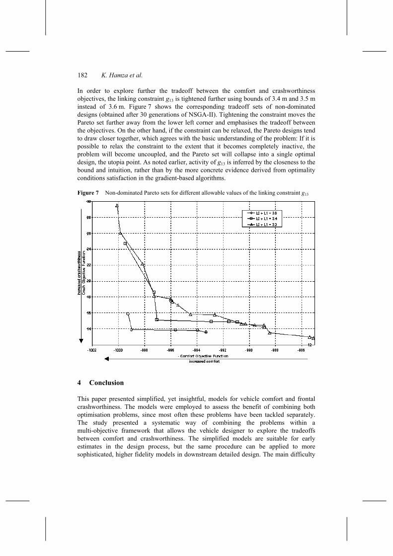
In order to explore further the tradeoff between the comfort and crashworthiness objectives, the linking constraint g13 is tightened further using bounds of 3.4 m and 3.5 m instead of 3.6 m. Figure 7 shows the corresponding tradeoff sets of non-dominated designs (obtained after 30 generations of NSGA-II). Tightening the constraint moves the Pareto set further away from the lower left corner and emphasises the tradeoff between the objectives. On the other hand, if the constraint can be relaxed, the Pareto designs tend to draw closer together, which agrees with the basic understanding of the problem: If it is possible to relax the constraint to the extent that it becomes completely inactive, the problem will become uncoupled, and the Pareto set will collapse into a single optimal design, the utopia point. As noted earlier, activity of g13 is inferred by the closeness to the bound and intuition, rather than by the more concrete evidence derived from optimality conditions satisfaction in the gradient-based algorithms.
Figure 7 Non-dominated Pareto sets for different allowable values of the linking constraint g13
4 Conclusion
This paper presented simplified, yet insightful, models for vehicle comfort and frontal crashworthiness. The models were employed to assess the benefit of combining both optimisation problems, since most often these problems have been tackled separately. The study presented a systematic way of combining the problems within a multi-objective framework that allows the vehicle designer to explore the tradeoffs between comfort and crashworthiness. The simplified models are suitable for early estimates in the design process, but the same procedure can be applied to more sophisticated, higher fidelity models in downstream detailed design. The main difficulty

Combined maximization of interior comfort and frontal crashworthiness 183
with higher fidelity models is the high computational cost, which makes them suitable for use in late refinement studies with a limited number of iterations.
Acknowledgement
This work was originally conceived as a class project in a graduate design optimisation course at University of Michigan. Additionally, we appreciate assistance provided by Prof. K. Saitou.
References 1 Klarin, M.M. and Cvijanovic, J.M. (1998) ‘The optimisation of the interior of the passenger
car’, International Journal of Vehicle Design, Vol. 19, No. 4, pp.448–453. 2 Klarin, M.M., Cvijanovic, J.M. and Brkic, V.K.S. (2001) ‘Additional adjustment of the driver
seat in accordance with the latest anthropometric measurements of drivers in Belgrade’, Proceedings of the Institution of Mechanical Engineers, Part D: Journal of Automobile Engineering, Vol. 215, No. 6, pp.709–712.
3 Lee, J.K., Jung, E.S. and Chung, M.K. (1999) ‘An investigation of relational characteristics among the design elements of automobile occupant packaging with a triangular method’, CybErg, CD-ROM Proceedings, pp.633–647.
4 Caputo, F., Gironimo, G.. Di Monacelli, G. and Sessa, F. (2001) ‘The design of a virtual environment for ergonomic studies’, XII ADM International Conference, Rimini, Italy, pp.42–54 (E1).
5 Porter, J.M. and Gyi, D.E. (1998) ‘Exploring the optimum posture for driver comfort’, International Journal of Vehicle Design, Vol. 19, No. 3, pp.255–266.
6 Park, S.J., Kim, C.B., Kim, C.J. and Lee, J.W. (2000) ‘Comfortable driving postures for Koreans’, International Journal of Industrial Ergonomics, Vol. 26, No. 4, pp.489–497.
7 Phlippart, N.L., Kuechenmeister, T.J., Ferrara, R.A., Arnold, A.J., Jr. (1985) ‘The effects of the steering wheel to pedal relationship on driver selected seat position’, International Congress & Exposition – Society of Automotive Engineers, Paper 850311P, Detroit, Michigan.
8 NHSSA (2003) http://www.nhtsa.dot.gov/ 9 Kurtaran, H., Omar, T. and Eskandarian, A. (2001) ‘Crashworthiness design optimisation of
energy absorbing rails for the automotive industry’, ASME IMECE2001/AMD-25452, New York.
10 LS-DYNA (2001) 960 Manuals, Livermore Software Technology Corporation. 11 Yang, R., Wang, N., Tho, C. and Bobineau, J. (2001) ‘Metamodelling development for vehicle
frontal impact simulation’, ASME DETC2001/DAC-21012, New York. 12 Chen, S. (2001) ‘An approach for impact structure optimisation using the robust genetic
algorithm’, Finite Elements in Analysis and Design, Vol. 37, No. 5, pp.431–446. 13 Saha, N.K. and Bhojan, R. (2001) ‘Influence of chassis and driveline components in vehicle
frontal crash,’ International Mechanical Engineering Congress and Exposition IMECE 2001, Paper AMD-25434, New York.
14 Michalewicz, Z. (1994) Genetic Algorithms + Data Structures = Evolutionary Programs, 2nd ed., Springer Verlag, New York.
15 Deb, K. (2001) Multi-Objective Optimisation Using Evolutionary Algorithms, John Wiley & Sons, New York.
16 Chaffin, D.B. and Andersson, G.B.J. (1984) Occupational Biomechanics, John Wiley & Sons, New York.

184 K. Hamza et al.
Nomenclature
Symbol Description and nominal value
bR Breadth of main rail cross-section [m] D Rail offset distance [m] dg Distance of closest visible point on the ground [m] dgmax Upper bound on dg (dgmax = 4 m) [m] emax Total energy absorbed by main rail [Nm] ereq Minimum energy required to avoid passenger injury (ereq = 1 × 10⁴ Nm) [Nm] hg Height of car bottom from ground (hg = 0.25 m) [m] hR Height of main rail cross-section [m] tR1 Thickness of main rail cross-section [m] tR2 Thickness of main rail cross-section [m] E Young’s modulus of elasticity (E = 207 × 109 N/m2) [N/m2] Gf Gender adjustment factor H Human body height [m] H0 Height of vehicle (H0 = 1.3 m) [m] H1 Height of lower part of A-pillar (H1 = 0.68 m) [m] H2 Height of lower part of C-pillar (H2 = 0.75 m) [m] Kbs Bending stiffness [N/m] Kbs,allowed Allowed bending stiffness (Kbs,allowed = 1 × 10⁵ N/m) [N/m] Kts Torsional stiffness [Nm/rad] Kts,allowed Allowed torsional stiffness (Kts,allowed = 1 × 10⁵ Nm/rad) [Nm/rad] L0 Length of cabin [m] L1 Length of the straight frontal portion of main rail
(L1 = 1.4 m) [m] L2 Length of the bent portion of main rail [m] Sy Material yield strength (Sy = 240 × 106 N/m2) [N/m2] TS Seat thickness (TS = 0.2 m) [m] VC Impact velocity of car [m/s]
Xα X-coordinate of the intersection between roof and A-pillar [m]
Xβ X-coordinate of the intersection between roof and C-pillar [m]
XB, YB Rear passenger hip point location [m] XE, YE Eye location [m] XF, YF Rear passenger foot location [m] XH, YH Driver’s hip point location [m] XP, YP Pedal location (XP = 0.15 m, YP = 0.1 m) [m] XS, YS Shoulder location [m] XSW, YSW Steering wheel location [m]
α Angle of A-pillar from vertical [°]
αe Elbow angle [°]

Combined maximization of interior comfort and frontal crashworthiness 185
αk Driver’s knee angle [°]
αkB Rear passenger’s knee angle [°]
αs Shoulder angle (x-y plane) [°]
αt Driver’s torso angle [°]
β Angle of C-pillar from vertical [°]
γ Angle of frontal part of the car from the horizontal (γ = 15°) [°]
δallowed_1 δallowed_2
Maximum allowed displacement of the straight and bent portions of the main rail (δallowed_1 = 0.9 L1 m, δallowed_2 = 0.35 m) [m]
δmax1 Maximum displacement of the straight portion of main rail [m]
δmax2 Maximum displacement of the S-frame [m]
φ1 Upward eye rotation [°]
φ1min, φ2min Required visibility angles upward and downward (φ1min = 12°, φ2min = 10°) [°]
φ2 Downward eye rotation [°]
ν Poisson’s ratio (ν = 0.3)
ρ Material density (ρ = 7800 kg/m3) [kg/m3]
θS Driver’s seat angle (θS = 110°) [°]
σb Bending stress [N/m2]
σpb Compression flange buckling stress [N/m2]