Embed Size (px)
Citation preview
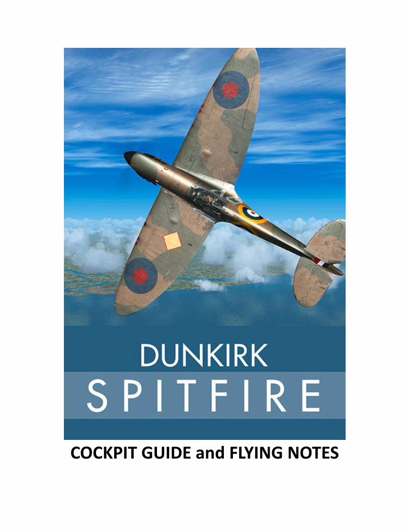
COCKPIT GUIDE and FLYING NOTES
2
CONTENTS
INTRODUCTION ............................................................ 3
AIRCRAFT PARAMETERS (for Mk1) ................................ 5
AIRCRAFT COVERED IN THIS SIMULATION ..................... 6
KEYSTROKES ............................................................... 12
MIRRORS.................................................................... 12
THE EVOLUTION OF EARLY SPITFIRES .......................... 13
COCKPIT GUIDE – Main Panel ..................................... 15
COCKPIT GUIDE - Throttle Quadrant ............................ 16
COCKPIT GUIDE - Right Side ........................................ 17
COCKPIT GUIDE - Left Side .......................................... 18
COCKPIT NOTES .......................................................... 19
IMPORTANT SIMULATOR SETTINGS ............................. 22
FLYING THE SUPERMARINE SPITFIRE MK1 ................... 23
CHECKLISTS ................................................................ 35
CREDITS & COPYRIGHT ............................................... 38

3
INTRODUCTION
When designer Reginald J Mitchell died of cancer in 1937, although having seen the prototype take to
the air the previous year, little could he have known just how much influence his brilliant design for an
all-metal, monoplane, eight-gun fighter would have on the outcome of the Second World War.
Spitfires fought from the earliest days of the War right through to its close in both the European and
Pacific theatres and continued to serve with distinction through more conflicts right up to the 1960s.
But, it was in the darkest days of 1940, when Britain was on the back foot following a disastrous
campaign in France and the evacuation from Dunkirk that Mitchell's graceful fighter really proved its
mettle.
Alongside the venerable Hawker Hurricane, its stablemate in many RAF squadrons of the day, pilots flew
the Spitfire into battle throughout each day of the summer of 1940.
The early Mk1 originally had a two-blade, fixed pitch, wooden propeller but during 1939, as with the
Hurricane, this was replaced with a three-blade metal, variable pitch airscrew. Early Mk1s were fitted
with an awkward hand-pump-operated landing gear system which proved difficult for novice Spitfire
pilots because it necessitated changing hands over from throttle to pump lever (leaving the left hand to
operate the control stick). This, in turn, could result in what was called ‘Spitfire wobble’. As the pilot
pumped away, his left hand would rock the stick back and forth in unison, producing the wobbling
motion. Pilots soon learned to master the system and avoid ridicule back at the mess! Another side-
effect was ‘Spitfire knuckle’ - suffered by pilots rapping their knuckles on the cockpit sides as they
pumped the handle.
In the Mk1A this awkward system was replaced by an all-hydraulic unit which had a simple lever with
gates to operate the landing gear. Both types can be found in this simulation.
Throughout 1940, apart from the landing gear controls, the basic design and layout of the Spitfire
remained unchanged. A larger ‘bubble’ canopy was also added to the Mk1A for increased head
clearance. This is how you can tell a Mk1A from an earlier Mk1.
The inspiration for this simulation comes from the stories of two early Spitfires which fell whilst
defending ground forces at Dunkirk. Both machines were re-discovered in the wet beach sands of
Northern France where they had lain forgotten for 40 years. The first is serial no. P9374 ‘J’. An early Mk1
flown by Fg Off Peter Cazenove on his first combat mission. With his aeroplane, disabled by a single
bullet from a Heinkel HE111 bomber, Cazenove was given no option other than to ditch in the sands of
Calais. Captured by the Germans, he was imprisoned in Stalag Luft III camp, the camp – made famous in
The Great Escape.
The second machine is serial no. N3200 ‘QV‘. This Mk1 was flown by Sqn Ldr Geoffrey Stephenson on an
operation over Calais protecting the BEF as they were evacuated on 27th May 1940. Stephenson's
machine was hit and force-landed on the beach. Later, taken prisoner and sent to the infamous Colditz
Castle, he was part of an escape plan involving the building of a glider, concealed in a loft area of the
castle.

4
N3200, like its sister, remained buried in the wet sands for more than 40 years until it was re-discovered
in 1986.
Both these aeroplanes were eventually restored to flying condition. P9374 taking to the air in 2011 and
N3200 in 2014.
They are among the earliest examples of Mk1 Spitfires currently flying and are a beautiful testament to
the skills of the restoration company responsible for their re-birth.
Also in this simulation you will find examples of Mk1As which fought in the Battle of Britain piloted by
some of that battle's aces.
In this guide we will take you through all the necessary steps needed to fly a Spitfire, point out some of
the design's unique features and get you as close as possible to feeling what it would have been like to
fly this incredible aeroplane.
So, strap on your Sutton harness and let's go!

5
AIRCRAFT PARAMETERS (for Mk1) LENGTH 29ft 11in
HEIGHT 11ft 5in
WINGSPAN 36ft 10in
WING AREA 242sq ft
EMPTY WEIGHT 4,246lbs
GROSS WEIGHT 5,819lbs
MAX. SPEED 295 MPH Indicated Air Speed @ 5,000 ft 2,475 rpm and +6.5 Boost
CRUISE SPEED 200 MPH Indicated Air Speed (best economy)
INITIAL CLIMB 975 FPM
SERVICE CEILING 31, 900ft
RANGE 400 miles
POWERPLANT Rolls Royce Merlin II or III 12-cylinder supercharged developing up to
1060hp
PROPELLER Variable pitch de Havilland, 9ft 8in diameter metal, 3-blade
6
AIRCRAFT COVERED IN THIS SIMULATION
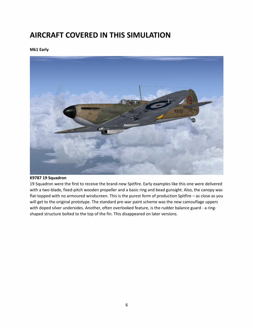
Mk1 Early
K9787 19 Squadron
19 Squadron were the first to receive the brand-new Spitfire. Early examples like this one were delivered
with a two-blade, fixed-pitch wooden propeller and a basic ring and bead gunsight. Also, the canopy was
flat-topped with no armoured windscreen. This is the purest form of production Spitfire – as close as you
will get to the original prototype. The standard pre-war paint scheme was the new camouflage uppers
with doped silver undersides. Another, often overlooked feature, is the rudder balance guard - a ring-
shaped structure bolted to the top of the fin. This disappeared on later versions.

7
Mk1 (early pump-operated landing gear, low profile canopy)
P9374 J 92 Squadron
Flown by FG Off Peter Cazenove 24th May 1940. Shot down and beached. Discovered in 1980; finally
restored to flying condition and first flown again in August 2011.
N3200 QV 19 Squadron May 1940
Flown by Sqn Ldr Geoffrey Stephenson, was shot down and beached. Discovered in 1986; finally restored
to flying condition and flown again in 2014.
8
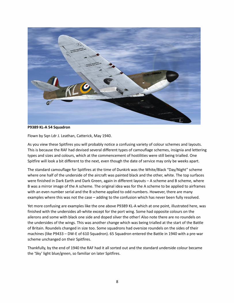
P9389 KL-A 54 Squadron
Flown by Sqn Ldr J. Leathan, Catterick, May 1940.
As you view these Spitfires you will probably notice a confusing variety of colour schemes and layouts.
This is because the RAF had devised several different types of camouflage schemes, insignia and lettering
types and sizes and colours, which at the commencement of hostilities were still being trialled. One
Spitfire will look a bit different to the next, even though the date of service may only be weeks apart.
The standard camouflage for Spitfires at the time of Dunkirk was the White/Black “Day/Night” scheme
where one half of the underside of the aircraft was painted black and the other, white. The top surfaces
were finished in Dark Earth and Dark Green, again in different layouts – A scheme and B scheme, where
B was a mirror image of the A scheme. The original idea was for the A scheme to be applied to airframes
with an even number serial and the B scheme applied to odd numbers. However, there are many
examples where this was not the case – adding to the confusion which has never been fully resolved.
Yet more confusing are examples like the one above P9389 KL-A which at one point, illustrated here, was
finished with the undersides all-white except for the port wing. Some had opposite colours on the
ailerons and some with black one side and doped silver the other! Also note there are no roundels on
the undersides of the wings. This was another change which was being trialled at the start of the Battle
of Britain. Roundels changed in size too. Some squadrons had oversize roundels on the sides of their
machines (like P9433 – DW-E of 610 Squadron). 65 Squadron entered the Battle in 1940 with a pre-war
scheme unchanged on their Spitfires.
Thankfully, by the end of 1940 the RAF had it all sorted out and the standard underside colour became
the ‘Sky’ light blue/green, so familiar on later Spitfires.
9
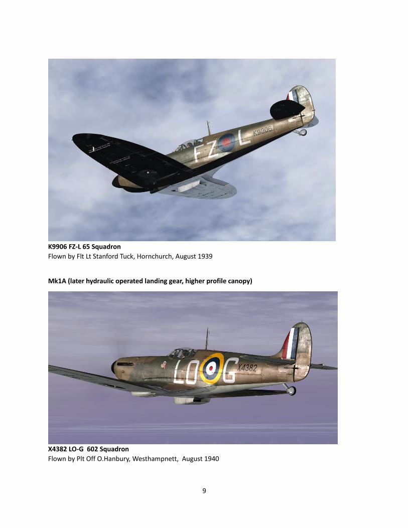
K9906 FZ-L 65 Squadron
Flown by Flt Lt Stanford Tuck, Hornchurch, August 1939
Mk1A (later hydraulic operated landing gear, higher profile canopy)
X4382 LO-G 602 Squadron
Flown by Plt Off O.Hanbury, Westhampnett, August 1940
10
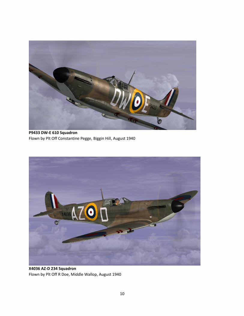
P9433 DW-E 610 Squadron
Flown by Plt Off Constantine Pegge, Biggin Hill, August 1940
X4036 AZ-D 234 Squadron
Flown by Plt Off R Doe, Middle Wallop, August 1940
11
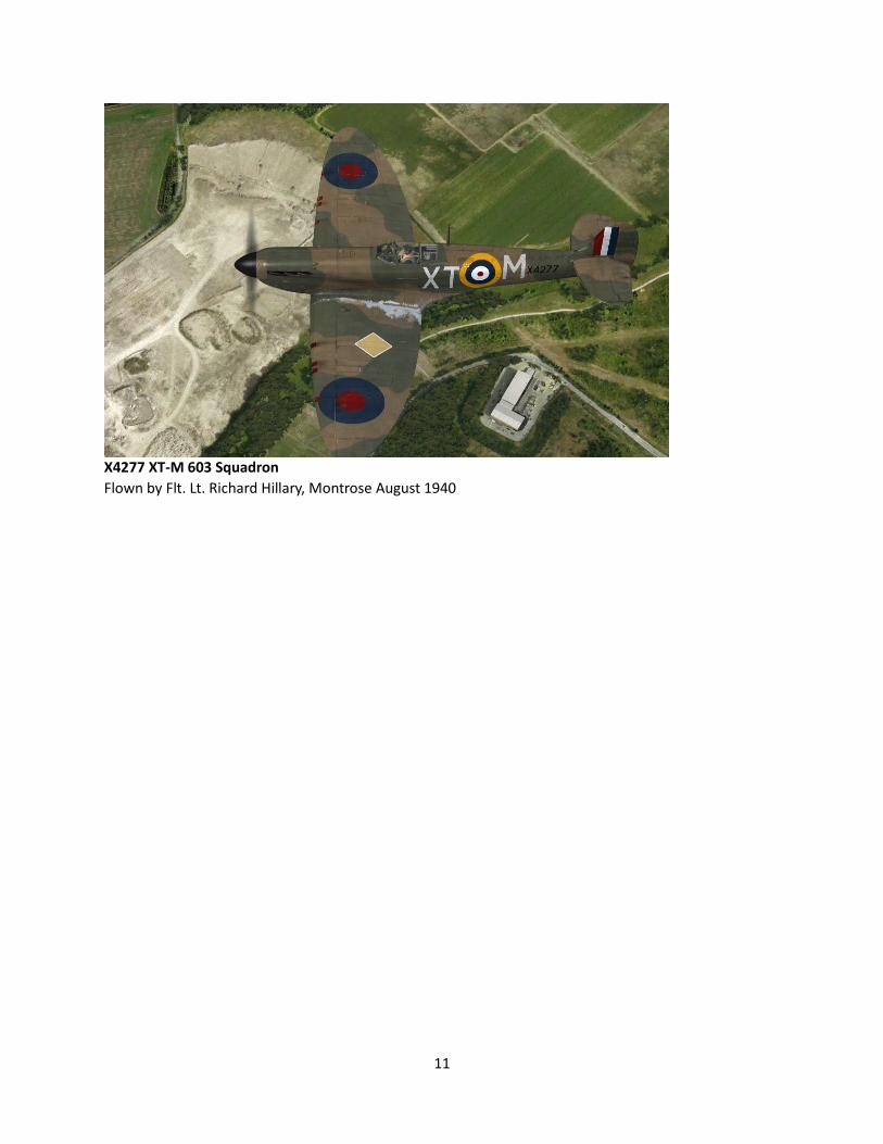
X4277 XT-M 603 Squadron
Flown by Flt. Lt. Richard Hillary, Montrose August 1940
12
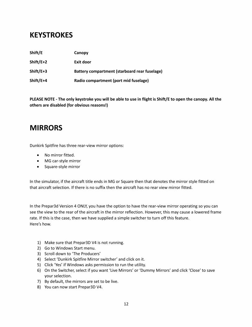
KEYSTROKES
Shift/E Canopy
Shift/E+2 Exit door
Shift/E+3 Battery compartment (starboard rear fuselage)
Shift/E+4 Radio compartment (port mid fuselage)
PLEASE NOTE - The only keystroke you will be able to use in flight is Shift/E to open the canopy. All the
others are disabled (for obvious reasons!)
MIRRORS
Dunkirk Spitfire has three rear-view mirror options:
• No mirror fitted.
• MG car-style mirror
• Square-style mirror
In the simulator, if the aircraft title ends in MG or Square then that denotes the mirror style fitted on
that aircraft selection. If there is no suffix then the aircraft has no rear view mirror fitted.
In the Prepar3d Version 4 ONLY, you have the option to have the rear-view mirror operating so you can
see the view to the rear of the aircraft in the mirror reflection. However, this may cause a lowered frame
rate. If this is the case, then we have supplied a simple switcher to turn off this feature.
Here’s how.
1) Make sure that Prepar3D V4 is not running. 2) Go to Windows Start menu. 3) Scroll down to ‘The Producers’ 4) Select ‘Dunkirk Spitfire Mirror switcher’ and click on it. 5) Click ‘Yes’ if Windows asks permission to run the utility. 6) On the Switcher, select if you want ‘Live Mirrors’ or ‘Dummy Mirrors’ and click ‘Close’ to save
your selection. 7) By default, the mirrors are set to be live. 8) You can now start Prepar3D V4.
13
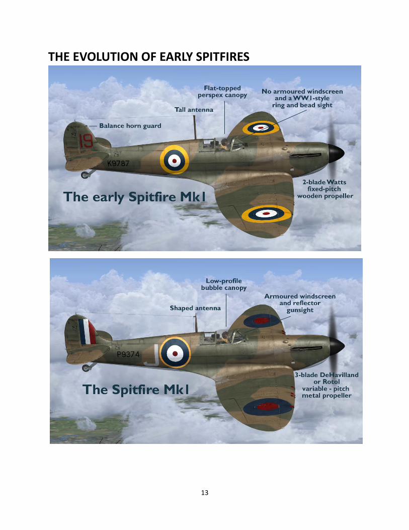
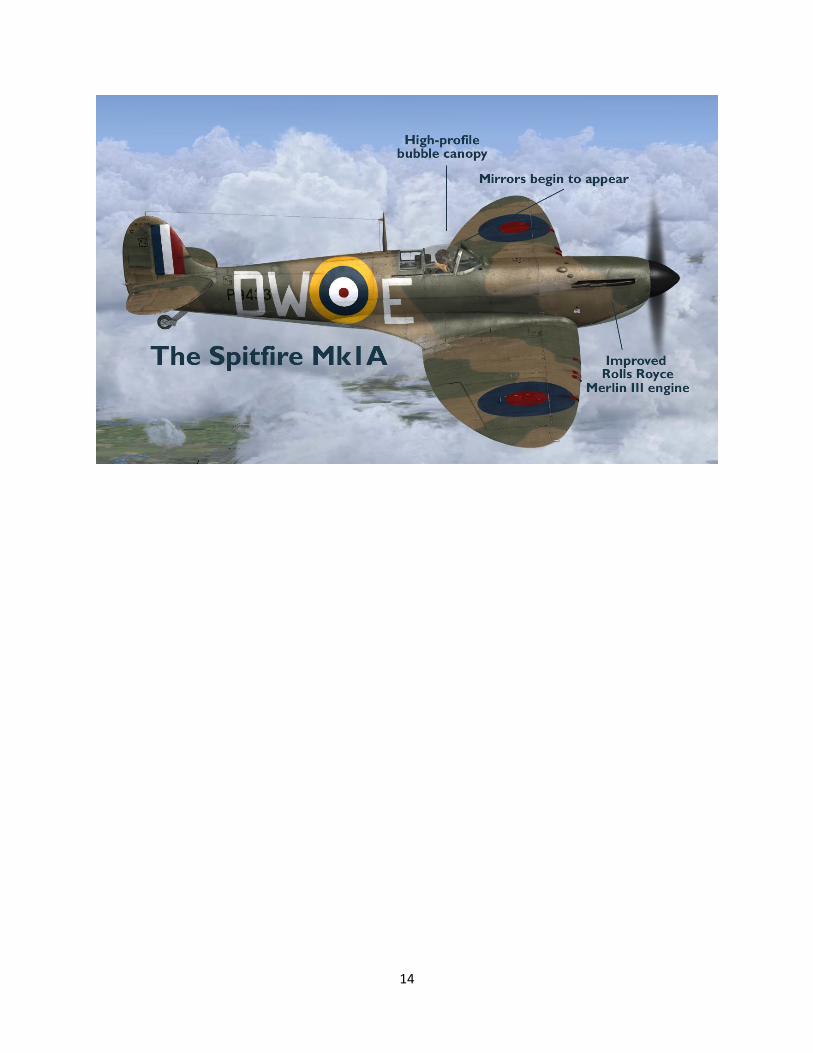
THE EVOLUTION OF EARLY SPITFIRES
14
15
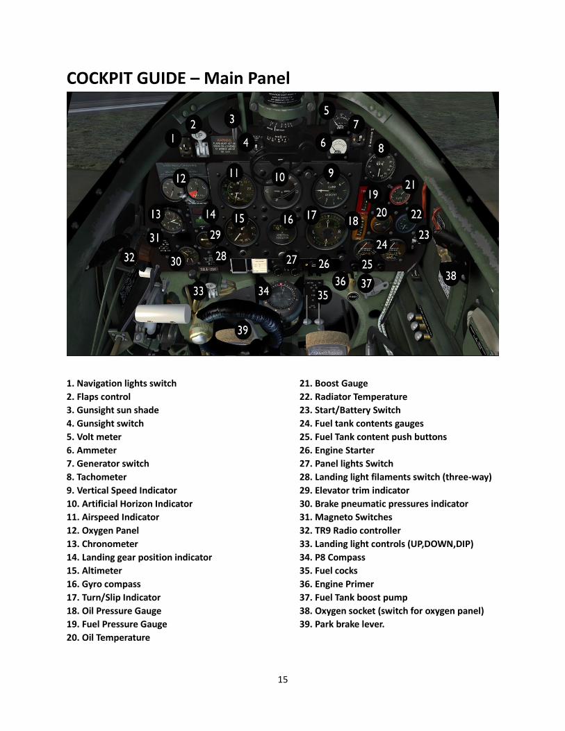
COCKPIT GUIDE – Main Panel
1. Navigation lights switch
2. Flaps control
3. Gunsight sun shade
4. Gunsight switch
5. Volt meter
6. Ammeter
7. Generator switch
8. Tachometer
9. Vertical Speed Indicator
10. Artificial Horizon Indicator
11. Airspeed Indicator
12. Oxygen Panel
13. Chronometer
14. Landing gear position indicator
15. Altimeter
16. Gyro compass
17. Turn/Slip Indicator
18. Oil Pressure Gauge
19. Fuel Pressure Gauge
20. Oil Temperature
21. Boost Gauge
22. Radiator Temperature
23. Start/Battery Switch
24. Fuel tank contents gauges
25. Fuel Tank content push buttons
26. Engine Starter
27. Panel lights Switch
28. Landing light filaments switch (three-way)
29. Elevator trim indicator
30. Brake pneumatic pressures indicator
31. Magneto Switches
32. TR9 Radio controller
33. Landing light controls (UP,DOWN,DIP)
34. P8 Compass
35. Fuel cocks
36. Engine Primer
37. Fuel Tank boost pump
38. Oxygen socket (switch for oxygen panel)
39. Park brake lever.
16
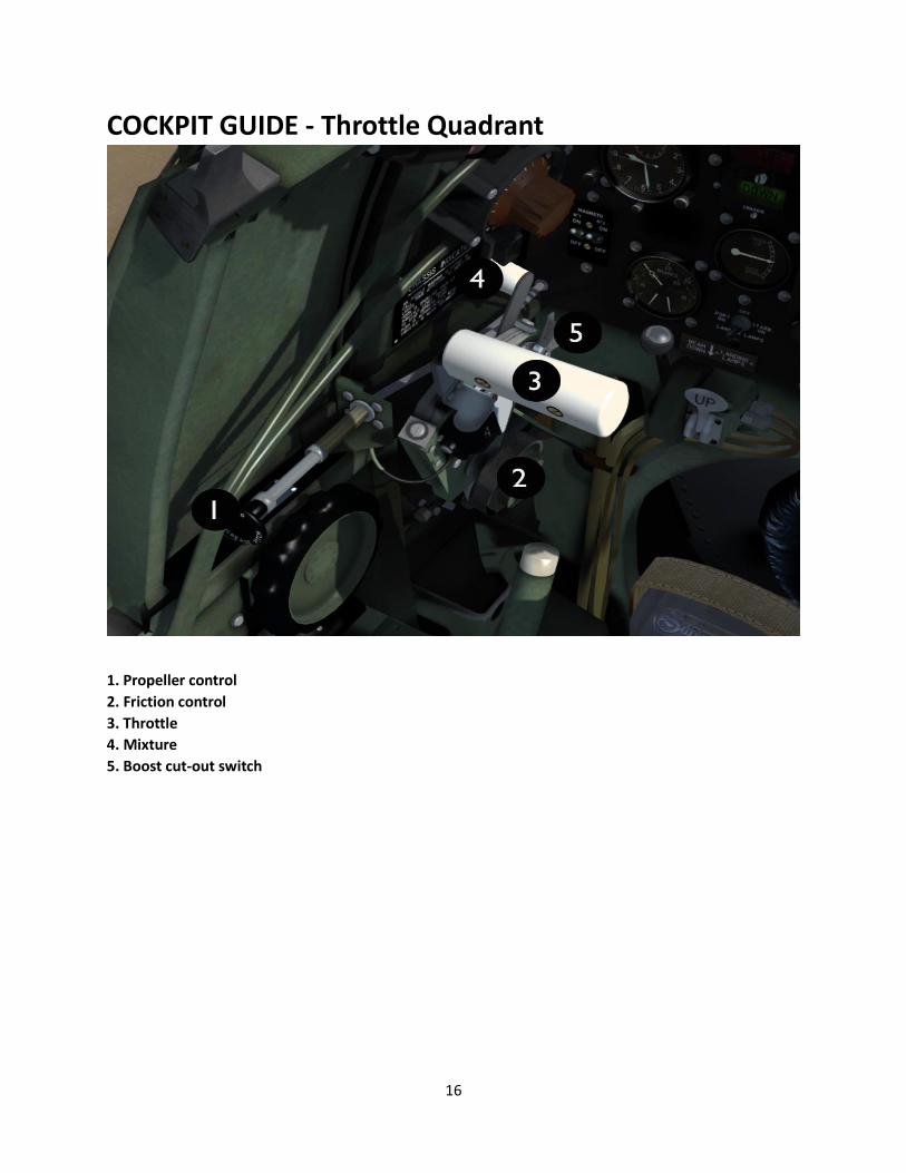
COCKPIT GUIDE - Throttle Quadrant
1. Propeller control
2. Friction control
3. Throttle
4. Mixture
5. Boost cut-out switch
17
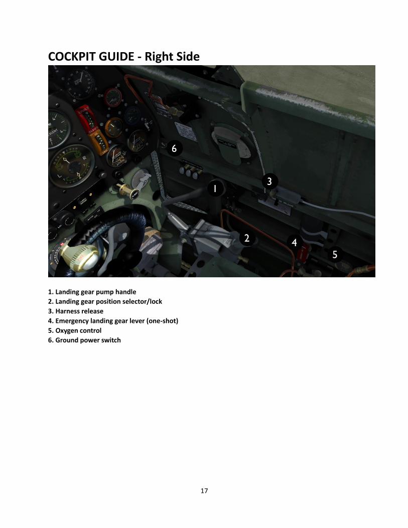
COCKPIT GUIDE - Right Side
1. Landing gear pump handle
2. Landing gear position selector/lock
3. Harness release
4. Emergency landing gear lever (one-shot)
5. Oxygen control
6. Ground power switch
18
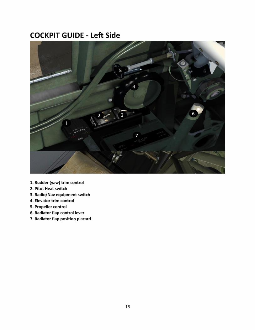
COCKPIT GUIDE - Left Side
1. Rudder (yaw) trim control
2. Pitot Heat switch
3. Radio/Nav equipment switch
4. Elevator trim control
5. Propeller control
6. Radiator flap control lever
7. Radiator flap position placard
19
COCKPIT NOTES The Mk1 and Mk1A cockpits are essentially the same except for the addition of a clockwork driven
‘contactor’ and hydraulic-powered undercarriage system fitted to the Mk1A. We will discuss the
differences as they occur in the flying guide. Please use the following guide plates as a reference for both
aircraft.
There are some non-standard items fitted to this cockpit for simulation purposes. These are:
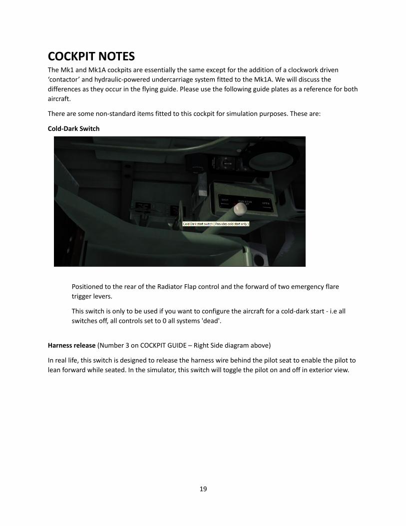
Cold-Dark Switch
Positioned to the rear of the Radiator Flap control and the forward of two emergency flare
trigger levers.
This switch is only to be used if you want to configure the aircraft for a cold-dark start - i.e all
switches off, all controls set to 0 all systems 'dead'.
Harness release (Number 3 on COCKPIT GUIDE – Right Side diagram above)
In real life, this switch is designed to release the harness wire behind the pilot seat to enable the pilot to
lean forward while seated. In the simulator, this switch will toggle the pilot on and off in exterior view.

20
Navigation suite
To aid modern navigation within the simulator, we have provided a set of radio receiver heads for
Navigation (VOR1), Comms (COM1) and ADF and an RMI (VOR/ADF ). The radio heads are buried deep
behind the armour plate behind the pilot seat. They are accessed with a special view window called
‘RADIOS’ that can be found when cycling through the VC window views. The RMI is only visible if you
use the toggle switch (Number 3 on COCKPIT GUIDE – Left Side diagram above) ahead of the pitot heat
switch.
1. ADF On/Off
2. ADF tuners
3. Comms On/Off
4. Comms frequency
5. MHz tuner
6. KHz tuner
7. NAV1 Frequency
8. NAV On/Off
9. MHz tuner
10. KHz tuner
21
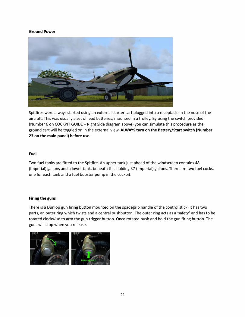
Ground Power
Spitfires were always started using an external starter cart plugged into a receptacle in the nose of the
aircraft. This was usually a set of lead batteries, mounted in a trolley. By using the switch provided
(Number 6 on COCKPIT GUIDE – Right Side diagram above) you can simulate this procedure as the
ground cart will be toggled on in the external view. ALWAYS turn on the Battery/Start switch (Number
23 on the main panel) before use.
Fuel
Two fuel tanks are fitted to the Spitfire. An upper tank just ahead of the windscreen contains 48
(Imperial) gallons and a lower tank, beneath this holding 37 (Imperial) gallons. There are two fuel cocks,
one for each tank and a fuel booster pump in the cockpit.
Firing the guns
There is a Dunlop gun firing button mounted on the spadegrip handle of the control stick. It has two
parts, an outer ring which twists and a central pushbutton. The outer ring acts as a ‘safety’ and has to be
rotated clockwise to arm the gun trigger button. Once rotated push and hold the gun firing button. The
guns will stop when you release.
22
IMPORTANT SIMULATOR SETTINGS
Please ensure that you set ‘Enable Automixture’ to OFF in your Flight Simulator to allow the
authentically coded automatic mixture control of the real Spitfire to operate. Failure to do this will result
in clouds of black exhaust smoke and a spluttering engine!
Due to the custom code used to authentically replicate the real Spitfire’s engine mixture system, you will
see a default flight simulator message pop-up saying ‘FLYING TIP. Your engine is losing power because
the mixture is not leaned correctly. To complete this action , press: CTRL + X’. That message is not correct
and can be ignored because the Spitfire automixture system is operating. If you wish to hide this
message, then follow these steps:
Prepar3D
OPTIONS>GENERAL>INFORMATION>INFORMATION TEXT>MISCELLANEOUS TEXT: and untick “User tips”.
NOTE this will also turn off all User tips.
Flight Simulator
From the main menu>SETTINGS>REALISM> Untick ‘Display Flying tips’.
23
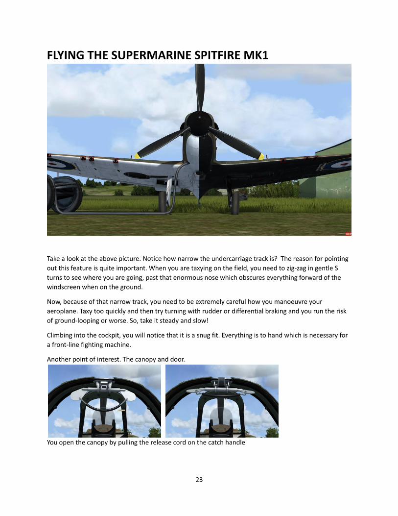
FLYING THE SUPERMARINE SPITFIRE MK1
Take a look at the above picture. Notice how narrow the undercarriage track is? The reason for pointing
out this feature is quite important. When you are taxying on the field, you need to zig-zag in gentle S
turns to see where you are going, past that enormous nose which obscures everything forward of the
windscreen when on the ground.
Now, because of that narrow track, you need to be extremely careful how you manoeuvre your
aeroplane. Taxy too quickly and then try turning with rudder or differential braking and you run the risk
of ground-looping or worse. So, take it steady and slow!
Climbing into the cockpit, you will notice that it is a snug fit. Everything is to hand which is necessary for
a front-line fighting machine.
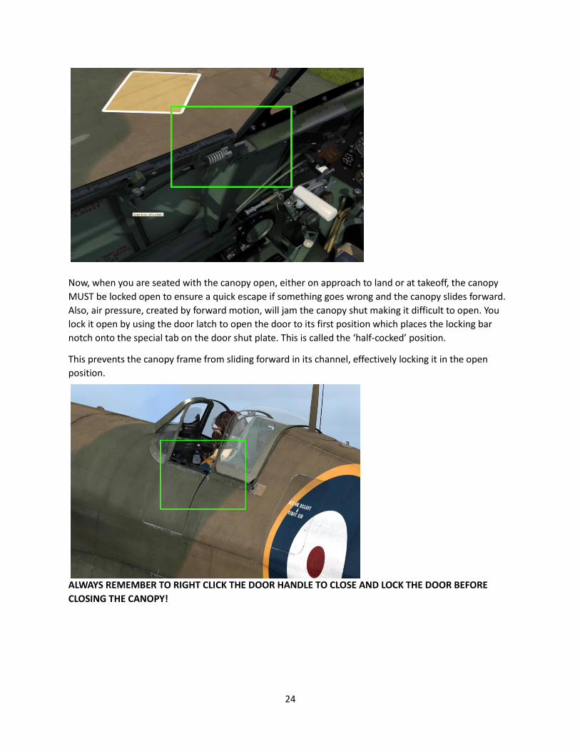
Another point of interest. The canopy and door.
You open the canopy by pulling the release cord on the catch handle
24
Now, when you are seated with the canopy open, either on approach to land or at takeoff, the canopy
MUST be locked open to ensure a quick escape if something goes wrong and the canopy slides forward.
Also, air pressure, created by forward motion, will jam the canopy shut making it difficult to open. You
lock it open by using the door latch to open the door to its first position which places the locking bar
notch onto the special tab on the door shut plate. This is called the ‘half-cocked’ position.
This prevents the canopy frame from sliding forward in its channel, effectively locking it in the open
position.
ALWAYS REMEMBER TO RIGHT CLICK THE DOOR HANDLE TO CLOSE AND LOCK THE DOOR BEFORE
CLOSING THE CANOPY!
25
NOTES ON THE CONTROLS
The flaps on a Spitfire are simple, pneumatically operated, ‘doors’ that drop into the airflow to increase
lift and drag to slow the aeroplane down. The flaps switch, therefore is either UP or DOWN. There is no
intermediate position. Flaps retract with the aid of airflow once pressure is relieved.
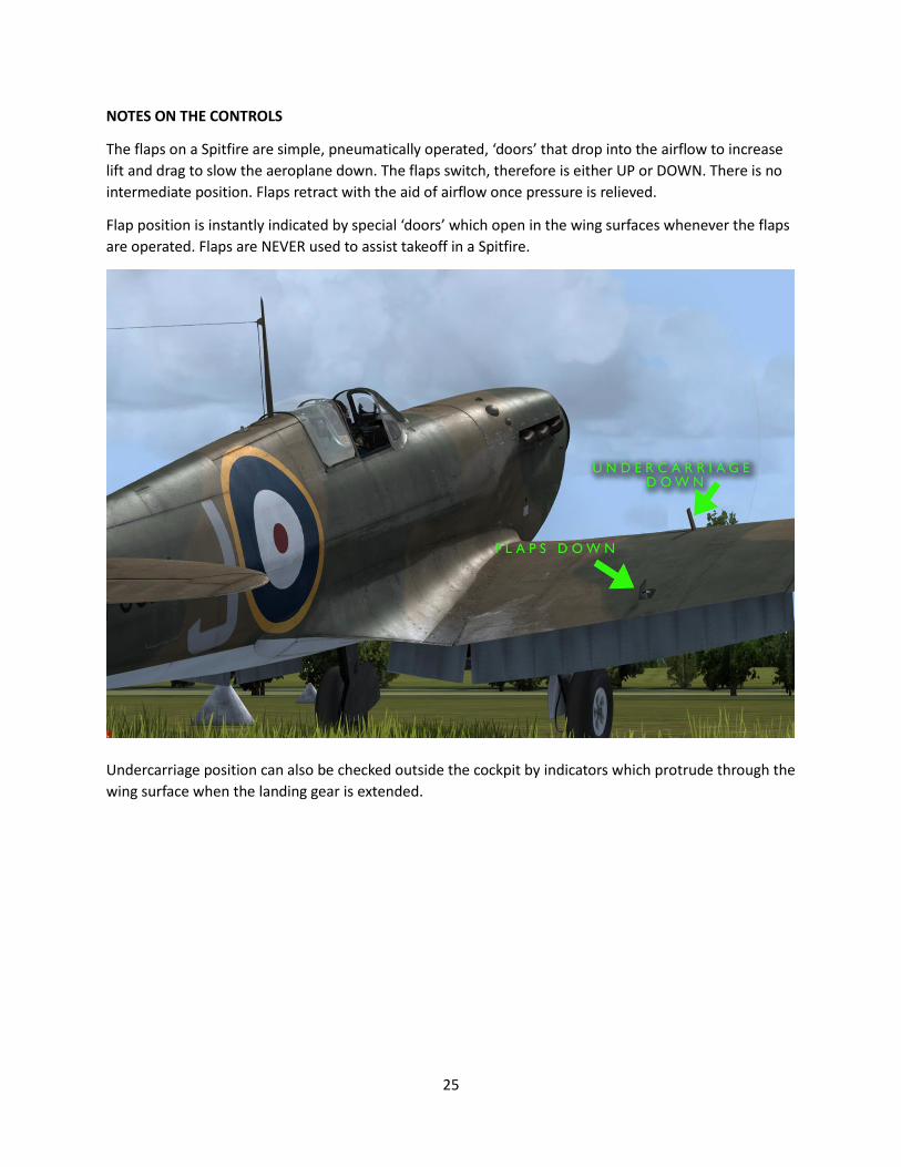
Flap position is instantly indicated by special ‘doors’ which open in the wing surfaces whenever the flaps
are operated. Flaps are NEVER used to assist takeoff in a Spitfire.
Undercarriage position can also be checked outside the cockpit by indicators which protrude through the
wing surface when the landing gear is extended.
26
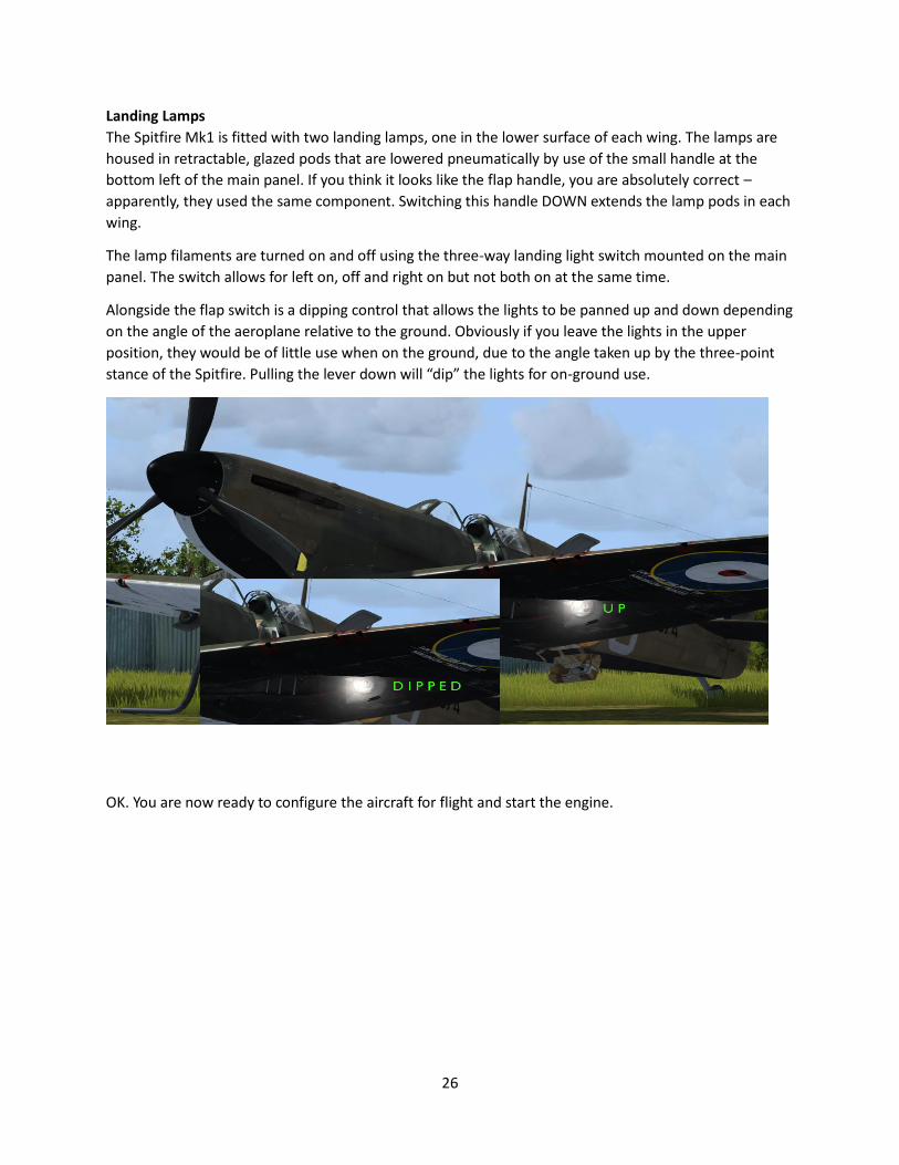
Landing Lamps
The Spitfire Mk1 is fitted with two landing lamps, one in the lower surface of each wing. The lamps are
housed in retractable, glazed pods that are lowered pneumatically by use of the small handle at the
bottom left of the main panel. If you think it looks like the flap handle, you are absolutely correct –
apparently, they used the same component. Switching this handle DOWN extends the lamp pods in each
wing.
The lamp filaments are turned on and off using the three-way landing light switch mounted on the main
panel. The switch allows for left on, off and right on but not both on at the same time.
Alongside the flap switch is a dipping control that allows the lights to be panned up and down depending
on the angle of the aeroplane relative to the ground. Obviously if you leave the lights in the upper
position, they would be of little use when on the ground, due to the angle taken up by the three-point
stance of the Spitfire. Pulling the lever down will “dip” the lights for on-ground use.
OK. You are now ready to configure the aircraft for flight and start the engine.
27
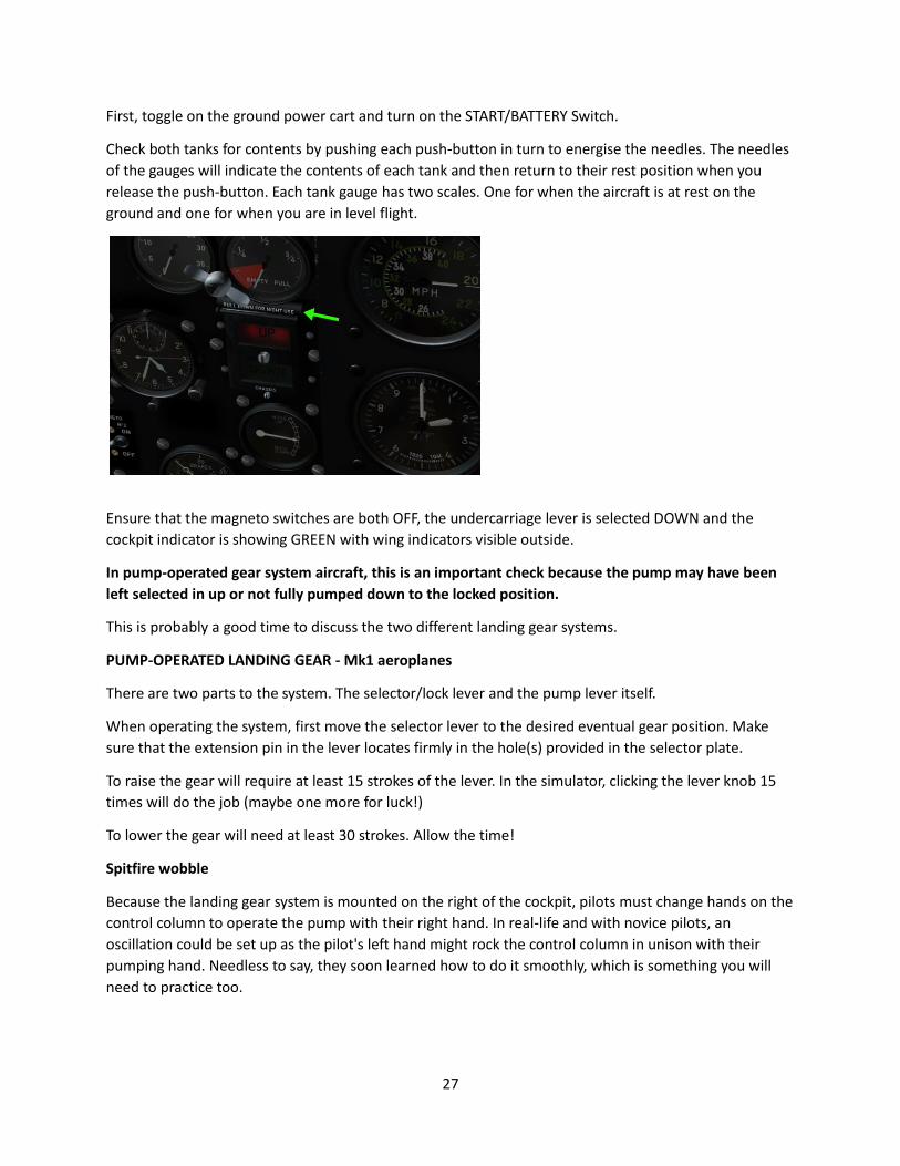
First, toggle on the ground power cart and turn on the START/BATTERY Switch.
Check both tanks for contents by pushing each push-button in turn to energise the needles. The needles
of the gauges will indicate the contents of each tank and then return to their rest position when you
release the push-button. Each tank gauge has two scales. One for when the aircraft is at rest on the
ground and one for when you are in level flight.
Ensure that the magneto switches are both OFF, the undercarriage lever is selected DOWN and the
cockpit indicator is showing GREEN with wing indicators visible outside.
In pump-operated gear system aircraft, this is an important check because the pump may have been
left selected in up or not fully pumped down to the locked position.
This is probably a good time to discuss the two different landing gear systems.
PUMP-OPERATED LANDING GEAR - Mk1 aeroplanes
There are two parts to the system. The selector/lock lever and the pump lever itself.
When operating the system, first move the selector lever to the desired eventual gear position. Make
sure that the extension pin in the lever locates firmly in the hole(s) provided in the selector plate.
To raise the gear will require at least 15 strokes of the lever. In the simulator, clicking the lever knob 15
times will do the job (maybe one more for luck!)
To lower the gear will need at least 30 strokes. Allow the time!
Spitfire wobble
Because the landing gear system is mounted on the right of the cockpit, pilots must change hands on the
control column to operate the pump with their right hand. In real-life and with novice pilots, an
oscillation could be set up as the pilot's left hand might rock the control column in unison with their
pumping hand. Needless to say, they soon learned how to do it smoothly, which is something you will
need to practice too.
28
In the simulation, try shifting your hands to operate your joystick with your left hand as you left-click the
pump lever with your right hand on the mouse. You'll soon get a feel of how awkward it was for the
novice Spitfire pilot.
Also, with 30 strokes to get the gear down it is difficult not to panic as you are approaching an airfield at
a suitable rate of knots, maintaining your approach angle and speed!
The key here is obviously to get your flaps and gear down early and approach your airfield at a more
leisurely pace until you have mastered the system.
Of course, you can always punch the G key but that would be cheating would it not?
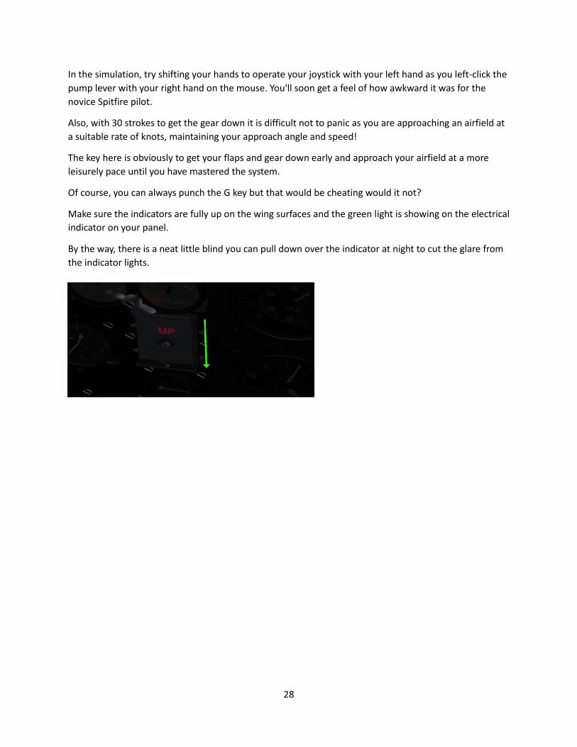
Make sure the indicators are fully up on the wing surfaces and the green light is showing on the electrical
indicator on your panel.
By the way, there is a neat little blind you can pull down over the indicator at night to cut the glare from
the indicator lights.
29
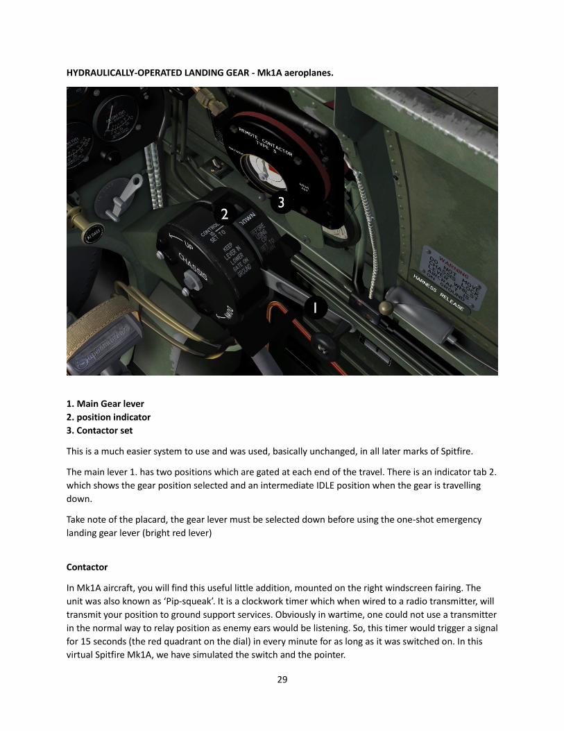
HYDRAULICALLY-OPERATED LANDING GEAR - Mk1A aeroplanes.
1. Main Gear lever
2. position indicator
3. Contactor set
This is a much easier system to use and was used, basically unchanged, in all later marks of Spitfire.
The main lever 1. has two positions which are gated at each end of the travel. There is an indicator tab 2.
which shows the gear position selected and an intermediate IDLE position when the gear is travelling
down.
Take note of the placard, the gear lever must be selected down before using the one-shot emergency
landing gear lever (bright red lever)
Contactor
In Mk1A aircraft, you will find this useful little addition, mounted on the right windscreen fairing. The
unit was also known as ‘Pip-squeak’. It is a clockwork timer which when wired to a radio transmitter, will
transmit your position to ground support services. Obviously in wartime, one could not use a transmitter
in the normal way to relay position as enemy ears would be listening. So, this timer would trigger a signal
for 15 seconds (the red quadrant on the dial) in every minute for as long as it was switched on. In this
virtual Spitfire Mk1A, we have simulated the switch and the pointer.
30
Back to the pre-flight procedures.
Check that the flaps are UP, wing indicators flush with the wing surface.
Similarly, check landing lamps are OFF (switch on panel) and UP (landing lamp control).
Check pressures in the brake system and apply the handbrake if not already on.
Before starting the engine be aware that the Merlin II and III engines do not take kindly to long periods
of idling on the ground. They overheat very easily and damage can result. So always make sure that you
are ready for flight before starting a Merlin.
Set the mixture control to full rich (all the way back – yes that's right, back. It is opposite to many other
aircraft)
Pull the propeller control all the way BACK to fine pitch.
Open the Radiator Shutter full open.
Raise both fuel cock levers to the top of their travel. Note: in this simulation, the fuel is not on until you
RELEASE the mouse button.
Open the throttle about 5%.
Unlock the primer (right-click) and pump (left click) about 4-5 strokes. Lock the primer again.
Switch on both magneto switches
Open the starter flap cover and press the starter.
During warm up, test the pneumatics by lowering and raising the flaps.
Ensure hood is locked open by placing the door in the half-cocked, second latch position
Engine tests:
IMPORTANT!!! Your aeroplane is fitted with a de Havilland 2-pitch airscrew. Push the propeller
control fully in to coarse pitch, lowest RPM. This is vital before opening up, as otherwise the thrust at full
power will nose the aircraft over.
A note on propellers
Two types of metal three-blade propellers were fitted to early Spitfire marks. Rotol variable pitch and de
Havilland 2- pitch. The DH item was intended to replace the old two-blade fixed pitch wooden prop fitted
to early Mk1s. Its advantage was to give better power in the climb and at altitude. The pitch range, from
coarse to fine was still, however variable with the control and it was soon discovered that operation of
the control at various power settings, despite the lack of a constant speed governor, could bring benefits
similar to the Rotol propellers. In fact, RAF Command eventually issued advice that the DH propeller
should be used as a variable pitch unit. The major difference is that the pilot MUST allow for the pitch of
the aircraft in determining the best propeller setting for power in a climb. In 1940, de Havilland issued an
upgrade for their 2-pitch propeller, turning it into a fully variable pitch type.

31
With RPM at LOW, open up throttle to maximum.
Now, very CAREFULLY and SLOWLY pull the propeller control back out to give around 2300RPM
Boost pressure should be at least +6.5 -7 pounds. The gauge will ‘pin’ at +8 but much higher boost can
actually be acquired. Later Spitfires had gauges which went up to +12 pounds.
Oil Pressure 80 psi
Test each magneto in turn by switching OFF first the RIGHT then back ON and then the LEFT OFF and
back ON. In each case you should see a small drop in RPM, no more than 100RPM.
Throttle back a little to give around +5.5 boost and pull the propeller control further back out to fine
pitch. This should give around 2600RPM. By easing back the throttle, check that there is no change in
RPM. The tachometer needle will flutter a little but should settle to maintain 2600RPM. This assures that
the constant speed aspect of the propeller system is working properly.
By now your radiator temperature will have risen somewhat alarmingly. Throttle back to idle as soon as
the tests are finished so as not to overheat the engine. Ensure that the radiator cooler flap is fully open.
Your oil temperature will also be high.
When taxying, a gentle S-shaped weaving is necessary to see forward of the aircraft. Remember the
point about the narrow undercarriage track and do not taxy too quickly with violent turns. You will end
up in a right mess.
When you reach your take off point, idle the engine and apply the parking brake.
RAF pilots had a catch-phrase to aid in remembering the following pre-takeoff checks.
T.M.P and FLAP
T – Trim nose-down one notch on the scale
M – Mixture BACK to FULL RICH
P - Propeller control fully back
FLAP – UP NEVER take off with flaps down.
To take off, open the throttle to maximum. Hold the stick slightly forward to keep the aircraft main
wheels planted but the tail up. Allow this configuration until take-off speed is achieved – around 85-90
MPH, then gently pull back the stick or allow the aeroplane to lift off. Any left-swing can be countered
with rudder. Sometimes it is helpful to feed in right rudder trim to aid in counteracting tail swing.
You will need approximately 1,200 ft of strip to take off at a speed of 86 – 90 MPH (IAS) with no head
wind.
Once you are airborne, follow the RAF catch-phrase U.P.
U – Raise the undercarriage. On pump-operated systems, keep the aircraft in level flight – do not climb.
Try to avoid Spitfire Wobble - it never looks good - and get the gear up before 140 MPH. Check the
indicators are flush on both wings and the RED indicator light is on via the cockpit indicator. The Spitfire
32
has asymmetric landing gear operation so one side will come up or down faster than the other. This is
why it is vital to check that all indicators are showing correctly.
P – Adjust the propeller control to give 2600 RPM
Continue to accelerate to 185 MPH and commence your climb.
Whilst you climb, (right-click) close the door latch and pull the canopy closed.
Close the radiator shutter.
Once at altitude, re-trim the aircraft to give hands-off stability.
Now you can relax in the cruise as we explore the Spitfire's performance envelope.
For 1940, this was a state-of-the-art fighting machine, so was designed for aerobatics and complex
manoeuvres. However, care must be taken not to overstress the airframe and strict guidelines for
aerobatics and high-speed flight must be followed.
Speed and Climb
The following figures are taken from official trials of a Mk1 Spitfire with Merlin II engine and a DH 3-
blade constant-speed airscrew.
Maximum Speeds using +6.4 Boost:
2, 000 ft 295.5 MPH (IAS) @ 2370 RPM
5,000 ft 294.5 MPH (IAS) @ 2475 RPM
10,000 ft 292 MPH (IAS) @ 2650 RPM
15,000 ft 288.5 MPH (IAS) @ 2820 RPM
20,000 ft 276.5 MPH (IAS) @ 2940 RPM
26,000 ft 240 MPH (IAS) @ 2855 RPM
30,000 ft 202 MPH (IAS) @ 2660 RPM
Best rate of climb to:
10,000 ft 2,490 fpm @ 174 MPH (IAS)
15,000 ft 2,065 fpm @ 168 MPH (IAS)
20,000 ft 1,480 fpm @ 157 MPH (IAS)
30,000 ft 325 fpm @ 135 MPH (IAS)
Note how the angle of pitch of the aeroplane is adjusted, the higher you go. If you do not do this, you
will stall the aircraft.
33
Stalling speeds
Flaps UP 69 MPH (IAS)
Flaps DOWN 63 MPH (IAS)
We will not be covering aerobatic or combat procedures in this manual. There are many excellent
reference sources available on-line and in official Pilot Notes that cover these aspects of flying the
Spitfire. Just remember to look after your engine first above all else. Do not run it at full power for any
more than short periods. Watch your oil and coolant temperatures and monitor your mixture control
and propeller pitch control constantly to achieve best performance at altitudes above 5,000 ft.
Approach and land
Allow plenty of time to set up your Spitfire for a landing back at base. First, reduce your speed to around
140 MPH (IAS) and adjust your attitude for a gentle reduction in altitude. Open the canopy and lock it
open using the half-cock position for the door.
Mixture should be at FULL RICH.
The radiator shutter can remain closed, providing the engine heat is within normal limits.
Lower the undercarriage. On pump operated system aircraft you will need to position the selector/lock
lever in the LOWER position, ensuring it is locked with the pin in the plate hole. Then commence
pumping for at least 30 strokes or until you see the green light on the electrical indicator and both
mechanical indicators are up on the wing surfaces.
If you experience problems with lowering the gear, use the one-shot emergency gear lever (red) which
should lower the gear. BE SURE TO HAVE THE SELECTOR LEVER IN DOWN/LOWER POSITION PIOR TO
USING THE EMERGENCY CONTROL.
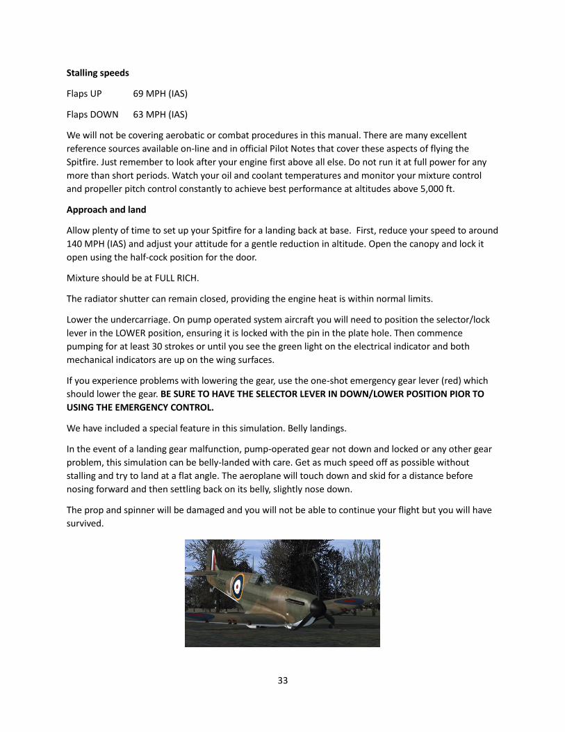
We have included a special feature in this simulation. Belly landings.
In the event of a landing gear malfunction, pump-operated gear not down and locked or any other gear
problem, this simulation can be belly-landed with care. Get as much speed off as possible without
stalling and try to land at a flat angle. The aeroplane will touch down and skid for a distance before
nosing forward and then settling back on its belly, slightly nose down.
The prop and spinner will be damaged and you will not be able to continue your flight but you will have
survived.
34
Continuing on approach, lower the flaps and adjust your power to maintain an approach speed of
around 90 MPH (IAS)
Best landing speed is approximately 60 MPH (IAS) for a three-point landing.
The Spitfire Mk1 is an excellent “side-slipper” in the right hands. It is encouraged to practice flat side-
slipping (rudder with opposite aileron input will skew the aircraft left or right) for cross-wind landings
especially. It was also a very useful correction to make in combat situations to bring the guns onto a
target.
Once down, raise the flaps and open the radiator shutter.
Move the pitch control forward (Mk1) to coarse pitch and taxy in.
35
CHECKLISTS
PRE-START
Ground power ON
Battery/Start switch ON
Magneto switches OFF
The undercarriage pump selector lever LOWER (check all indicators)
Flaps UP
Parking Brake lever ON
Fuel Tanks CHECK CONTENTS
Radiator Flap FULLY OPEN
Fuel Cocks OPEN - UP
ENGINE STARTING
Brake Pressures CHECK
Magnetos BOTH ON
Propeller control FULLY OUT FINE PITCH
Primer UNLOCK THEN 5 STROKES
Mixture lever BACK FULL RICH
Starter LEFT COVER AND PRESS
Oil Pressure CHECK
ENGINE CHECKS AND WARM-UP
Propeller control Fully IN COARSE PITCH
Throttle 100%
Boost CHECK at least +7
Propeller control EASE BACK to give 2600 rpm
Magnetos CHECK EACH (maximum 100 rpm drop)
Throttle IDLE
Propeller control FULLY OUT FINE PITCH
36
TAKEOFF
Elevator Trim 1 notch nose DOWN on gauge
Mixture BACK FULL RICH
Propeller control Fully OUT FINE PITCH
Flaps UP
Gauges CHECK ALL for normal functions
Parking Brake RELEASE AND HOLD ON TOE BRAKES
Throttle EASE FORWARD
Brakes RELEASE
Throttle 100%
Apply rudder to counteract swing
CLIMB
Landing gear Select RAISE and pump 15 strokes
Set throttle/boost and RPM to settings indicated in best climb rate figures in flight notes.
Radiator Flap Red Dot on placard.
CRUISE
Set throttle/boost and RPM to settings as required or to give best economical cruise as per flight notes
APPROACH and LANDING
Airspeed 160 MPH (IAS) and lowering
Flaps DOWN check indicators on wings
Landing gear Select “LOWER” and PUMP 30 strokes (at least)
until electrical indicator light shows green and
wing indicators are UP
Mixture FULL RICH
Propeller FINE PITCH
Airspeed 80 MPH (IAS) at threshhold
37
Touchdown 3-point @ 60 MPH (IAS)
Flaps UP once on ground
Propeller FULLY IN COARSE PITCH.
Radiator Shutter OPEN
SHUT DOWN
Mixture FULLY IN - CUT

38
CREDITS & COPYRIGHT
Developed and designed by Aeroplane Heaven
Distributed by The Producers Ltd.
Thanks to Richard at Fink Creative and T. E. Lawrence
© Copyright 2018 Aeroplane Heaven. All rights reserved. All trademarks and brand names are
trademarks or registered trademarks of the respective owners and their use herein does not imply any
association or endorsement by any third party.