Embed Size (px)
Citation preview

I• ._...rm
IP O • "*
, N65 19696"• ILA.CGmrlS•|ONNUHISJR_ _rH IIIu |
,._ ___ , . /_"_ (mE PRICE(S) $ -_qJUIA ¢R OR C_TmrGORY)
._,d copy(.c) ,_. d-_.
.,c.o.c_e,.._ /'_ d

"O " (3 0 0 ¢"0 O,,-
i' f ..... _ ......... "
L
il Interim Sugary Report for 1 November 1961 through31 March 1962
j_ _SE_CH _ DE_LO_NT OF HIGII EFFICIEN_
Prepared for
[ Headquarters
National _ronautics and Space _ministration
801 19th Street N.W., Room 526
Washington 25_ D. C.• _ Attn: Mr. Walter Scott, Code DA =
Contract No. NAS 7-86
• EOS Report No. 2100-1R-I 10_y 1962
[
i -M. A. Plche) Lee g. SprieSt 3 _erProject Supervia0r Engineering_elop_nt Dept.
_[ _ Approved by
Neusteln_ _nager_V_CED P_R SYST_S DIVISION
[, ..
ELEC_O-0_IC_ SYST_S, INC. - PASADENA, CALIFORNIA ' ,
i
1965010095-002

CONTENTS
ABSTRACT
i. INTRODUCTION
= i.I Review of Prior Concentrator Development at I
Electro-Optical Systems_ Ing.
1.2 Summary of Program Goals 8
1.2.1 Backing Structure Studies 8
1.2.2 Plating Techniques 9
1.2.3 Advanced Coating Studies I0
1.3 Program Schedule II
1.4 Summary of Report II
1.5 Definitions 12
2. BACKING STUDIES 17
2.1 Investigation of Backing and Support Structures 18for 5-Foo= Diameter Concentrators
2.2 Application to Larger Sizes . 19
2.3 Small-Scale Experimental Studies 20
2.3.1 Backing Master Considerations 20 J
2.3.2 Support Structure Attachment Methods 21
2.3.3 Evaluation of Various Concepts - 21
Experimental Fabrication
2.3.4 Effects of Plating Stresses 27
2.4 Developmevt of 5-Foot Diameter Concentrators 28
2.4.1 Preliminary Design Concept 28
2.4.2 Speci-I _ooling 30
2.4.3 Fabrication of Preliminary Models 38
3. DEVELOPMENT OF PLATING TECHNIQUES 44
3.1 Small-Scale Studies 44
3.1.1 Solution Analysis and Controls 44
3.1.2 Stress Determination and Control 46 "
2 IO0-1R- t - i = _
1965010095-003

CONTENTS (Continued)
3.!.3 Chromium as a Surfacing Material 50
3.1.4 Monitoring of Solution Additives 53
3.2 Detennination of Physical Properties of 54Electroformed Naterial
3.2.1 Variations in Physical Properties 54
3.2.2 Improvement in Physical Property 58
4. ADVANCED COATING STUDIES 132
4.1 Small-Scale Studies 132 =J
4.1.1 Effects of Maoter and Substrate Materials 132
4.1.2 Various Coatings for High Reflect_vity 133
4.1.3 Coating Adhesion and Durability Studies 138
4.1.4 Methods of Protection and Cleaning 142
4.2 Applicatzon of Protective Coatings 142
4.2.1 Pl'e-treatmentj CleaILing_ Etc. 143
4.2.2 Facility Requirement 143
5. SUMMARY 145
3
2100-lR-1 il,
1965010095-004

f
t_
LIST OF ILLUSTRATIONS
Fif_re
I- I Project Schedule 15
2- i Attachment Methods -Rear Torus Rigldized Mirror 22
2- 2 18-inch Diameter Mirror Skin with Chain Attached 24
2- 3 Close Up of Chain Lock Detail 24
2- 4 Close bp of Torus Attachment 25
2- 5 Preparation of Master for Edge Band Method 25
2- 6 Preparation for Attachment of Torus 26 :
2- 7 18-1nch Diameter Mirror Rigidized with Rear Mounted 26
Torus Showing Lack of Edge Roll
2- 8 Torus Rigidlzed 60-inch Diameter Lightweight 29Concentrator
2- 9 Electroformed Mounting Segment 31
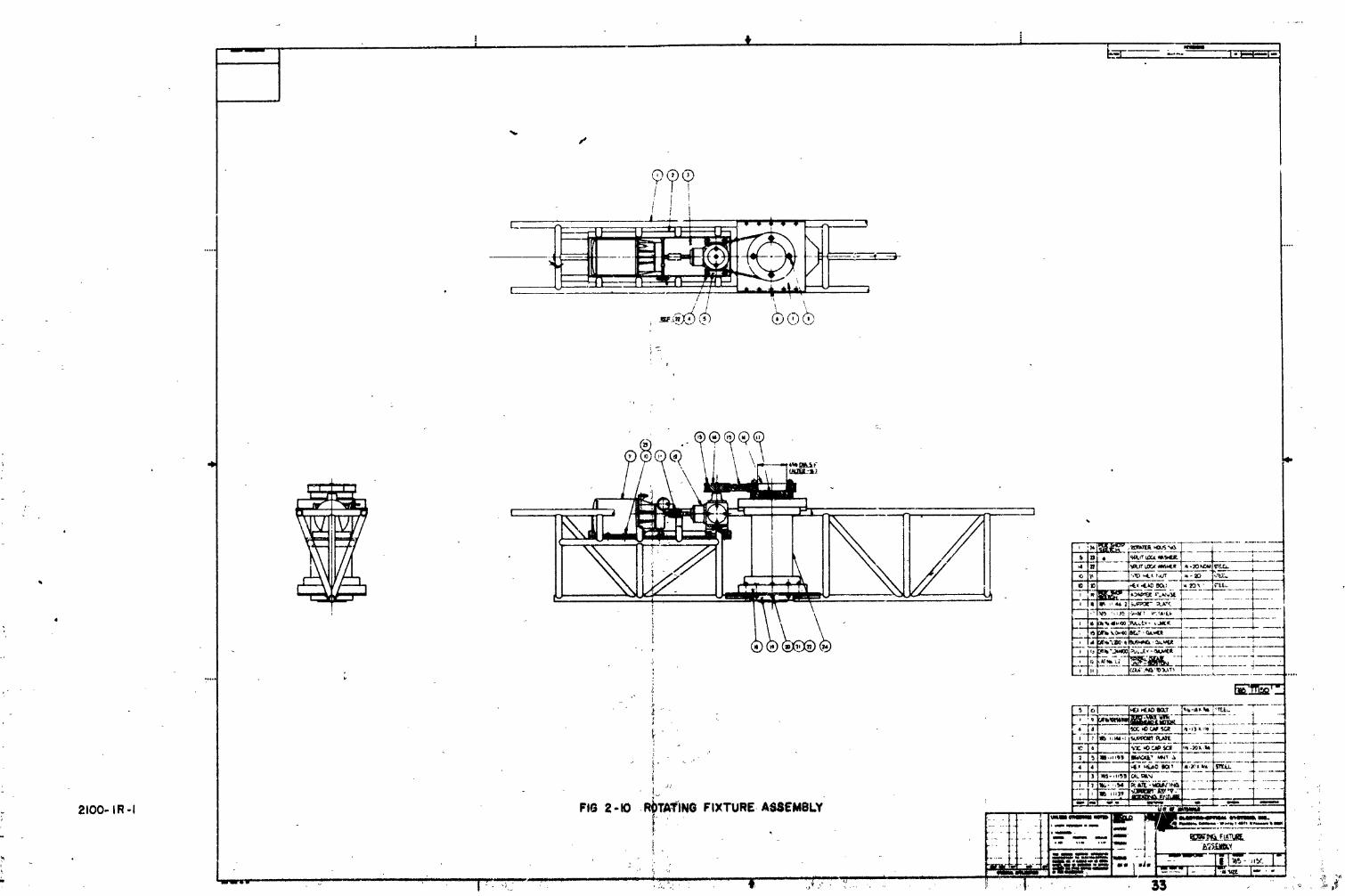
2-10 Rotating Fixture Assembly 33
2-11 Rotator Housing Assembly 34
2-12 Support Assembly - Rotating - Fixture 35
2-13 Support Fixture Extension 36
2-14 Rotator Assembly and Extensions 37
2-15 Swivel Fixture-Mirror Handling Equipment 39
2-16 Mirror Handling Fixture - HorLzontal Mirror Position 40
2-17 Mirror Handling Fixture - Vertical Mirror Position 40
2-18 Electroformed Torus Mounting Sections 41
2-19 Rim Tooling for 60-inch Diameter Torus Attachment 4i
2-20 60-1nch Diameter Plating Fixtuce for Experlmental 43Rear Mounted Torus
3- 1 Plating Research and Analygls Laboratory 45
-3- 2 HL,II Cell Testing 45
/
2100-1R-I iii
1965010095-005

I" _,IST OF ILLUSTRATIONS
I (Continued)
y ure£
3- 3 Monitoring and Control Equipment _ 47
3- 4 Modified Strip Test Y_xture 47
- 3- 5 Stressometar 49
-' 3- 6 Stress vs Current Density for Typical Nickel Sol,Jtion 51 =
" ., 3- 7 Stress vs Current Density for Typic&l Modified 52j., Copper Solution
3- 8 El_c_roformed Te_t Coupons and Reflectivity Samples 55
i! 3- 9 Parametric Trends Affec.:ing Young_s Modulus in 59Electrodeposited Nickel
I- 3-10 Sample F-3 64
t_ 3-11 Sample F-15 69
,. . 3-12 Sample F-17 " 73
I. 3-13 _ampta F-18 77
3-14 Sample F-21 _2
I! 3-15 Sample F-22 86
3-16 Sample F-23 91
3-17 Sample F-25-I _5
3-18 Sample F-26-I I00
r 3-19 Sample F-28-I i_'+
I' 3-20 Sample F-29-I 109
.. 3-21 Sample F-32-I 113
I 3-22 Sample F-33-I i18
3-23 Sample F-36-I 122
If 3-24 Sample F-37-I 126
3-25 Sample F-39-I 131
_[:" 4- 1 ,,,Plating of Reflectivlty Samples 1344- 2 Reflectlvity Samples - Rooftop Exposure 134
Iii - 4- 3 Reflectivity of Rhodium and Chzome 141Surfaces on Nickel
2100-IR-I iv
1965010095-006

ABSTRACT
This report describes work performed during the 5-month period
starting I November 1961 and ending 31 March 1962_ under Cuntract No.
NAS 7-86. This research and development contract is related to the
developmeDt and improvement of techniques for fabrication of high ef-
ficiency 3 lightweight solar concentrators. The first portion of the
: program has been chiefly concerned with investigation of backing and
_" sup_or_t structures_ for 5-foot diameter concentrators and the evaluation'- t'
of parameters relative to their application to concentrators of larger
sizes. Stress has been placed on the design and structural'approaches
of ele_troforming and the application of this technique to the pro-
duction of co_centrators. Necessary special tooling zequired for the
fabrication of 5-foot diameter concentrators has been deslgned an_
produced in preparation for experimental fabrication .of units of this
size during the remainder of the program.
A number of supporting and investigatory studies have been carried
on relatlve to the parameters affecting the electroforming of a variety
of materials sui=able for use in concentrator fabrication I with
emphasis on electroformed nickel and copper. Testing of the physical
properties of electroformed samples made under a wide range of con-
ditlons has been initiated and it appears that a relatively wide varia- '
tion in physical properties can be obtained cn a controlled basis.
Various reflective and p_otectlve coatings have also been,lnvestigated
for use with concentrators produced by the electroforming process and
their durability under various e'ivironmental conditions is in the pro-
cess of beLng evaluated. _t2_/
!2I00 -IR-1 :
1965010095-007

_d
[. INTRODUCTIDN
Electro-Optical Systems has, for a number of years, been ircensely
interested in solar energy conversion and has engaged in a number ofi
: study and developmental programs in this area. Since detailed infor-
mation has already been_set forth in the reports resulting from these
prior activities, an extensive review will not be included here. The
program3, resultant reports, and a brief description of the area of
i" activity, are listed in the following paragraphs_ A familiarity with
I the information contained in these past reports will be beneflcial in
the understanding and evaluation of the present area of activity.V"
_i, Definitions of terminologies and descriptive phrases used in this
report are contained in paragraph 1.5.• L
/' 1.l Review of Prior Concentrator Development at-I' Electro-Optical Systems. Inc.
An extensive one-year ef£u_t, LcLh a_lalyticaland experimental,
I concerned with the design aud dcvelopme[t of solar concentrators a_d
their integration into space power systems, was performed by EOS for
!i the Army Ballistic Missile Agency, Huntsville, Alabama, under Contract
DA-04-495-506-ORD-1790. _e program involved a comprehenslve study
[ coverlng a wide range of subjects including details of system,_c_signI.
requirements and design daLa_ basic concentrator design couzi_,_ationsl
" thermal energy converters, con_untrator size requireme_ts, _,_destimateso£some component weights and Ji.,ensions. Concentrator st;_ctucal and
fabrication techniques were distressedand included ele_.c,_t,of concen-
trator structure_ concentrator design tonslderat_ou_; f_,_cation tech-
niques, and materials. The experimental development Fhlses of the
I program included fabrication of small-scale sample c,,_centrators. A
wide variet_ of fabrication processes were investi_a_.ed to establish
I" advantages disadvantages o_ _ach.the and
Explosive forming, spin foz_ing, stretch formings matched-dye
'! forming, and other similar processes that were, evaluated involved actual
2100-1R-I t
I[
1965010095-008

!/
deformation and physical realignment of the skin material to conform
with the forming die, tool, or mandrel used in the fabrication process
In addition to this deforT_ation and stretching of the material itself,
the part was required to come iu physical contact with the face of
the nandrel or tool_/uring the course of forming° As a result, _L
was found to be impossible to maintain the surface accuracy and
polish required for high efficiency concentraLor perfor_,ance with-
out repolishing after the forming process was completed. Subsequent
polishing operations were found to be difficult, if not impossible,
to carry out on the thin-skln structures thai were [equired for
achievement of very low specific weight (pounds per square foot of
surface area). For these as well as other consideratic_s, the
formation of the concentrator reflector face skins by these more
conventional methods was considered far from optimum; consequentiy 3
a better fabrication process was desired.
To eliminate the need for reforming or repolishing the con-
centrator reflective-face materla!, various techniques for producing
a structurali7 sound, ligh_wei_it, highly reflective face skin by
replicating an acc,,rate master were considered. One of the most
extensively developed techniques for such replication involves the
use of plastic materials, beth filled and unfilled, which obtain their
structural integrity through the _se of backing structures such as glass
laminates and honeycombs. Unfilled plastic materials, both in the
polyester and epoxy categories, were found to have the ability to
reproduce surface chdracterlstics very accurately and, with proper
coatings, c_uld exhibit rcflectivities very nearly approaching those
obtainable with coated glass. Unfilled plastic materials were found
to be relatively unstable# however_ and highly accurate geometries could
not be maintained. These materials were also found to have very little
strength in themselv_ and_ as a conseq-encej proper backing structures
were required for ade_uste supper=. Moreover_ these materials may
be subject to degradation due to ul_ravloleL radiation and other
space factors. Filled plastic resins were relatively more stable_
2100-1R-I 2
i
1965010095-009

f
• but were found to lose the ability to maintain good surface character-
istics, The ._urfaces very often develoved a minute "orange peel"
effect that resulted in a deC.inlt= loss of re£1ectivitv.
Dt_rlng the co,trse of e.<tensi':e r._pecimental cvdluat/on of
replicated plastic- surface_, rigidiz_ by various means, a definite
showthrough of the backing _truct.re was experienced. Samples were
prepared both by EOS and outside vendors employing various types
of honeycombs, b_th metal]i_ ar_ non-metallic. Foams of varyil_ d_n-
sitics and formulation_ were also evaluated. In all cases wheru thick-
nesses needed to produce structures with reasonable weights were used,
_howth_ough and distortion were evident. In the case of honeycombed-
backed_structures, this showthrough appeared in the for.n of the cell
stracture of the honeycomb, and was cat.__ed by residual stress and shrink
of the materials used to bond the backing structure to the reflective
surface. In the case of foam backing, the distortion was not so clearly
defined but progressed with ti_e in the forming of an exaggerated and
nonuniform "orange peel" effect. This condition was accelerated with
large temperature changes and resulted in considerable loss in mirror
efficiency.
The ability of plastic resins ,,_,_drelated materials to with-
stand space environment has not a_ this time been satisfactorily demon-
strated. The combinations of these varlous-materials required to de-
velop a suitable ._tructure can result in heat transfer and other thermal
characteristics that, in turn_ can adversely influence the geometry of
t_a structure. Althcu6h beln8 unquestionably useful for some applica-
tlons_ these methods of fabrication (as was the case with methods
involving reforming of metailic skins) were considered to have serloasJ
drawbacks for hlgh-effi_lency, Xong-life concentrators.
During the cours_ of these _investlgatlons the process of
repllcatlon by electroformln8 was also evaluated. This process
appeared to offer solutions to many ot the important problems
inherent in other methods and made possible very accurate surface
2]O0-1R- I 3
1965010095-010

f
replication of the master. Extensive tests on electroforms replicated
from optically ground and polished glass masters demonstrated reflectivity
dlaracterlstics essentially identical with those of the master from which
they were replicated. Moreover, it appeared possible to achieve, through
further-development and refinement of the process, reflective face skins
and structural parts that would have low internal or residual stress.
As a result, the geometry of the master should be reproduced accurately.
In order to fully evaluate the possibtlitles that the electro-
forming process seemed to offer, a number of electroformed reflective
skins and structures were produced by outside vendors for evaluation.
From these structures the ability of the electroforming process to pro-
duce reflective surfaces comparable to gla_s mirrors was verified beyond
doubt. Problems existed, however, in two basic areas: (I) improvement
and refinement of the state-of-the-art of electroforming was needed to
gain greater control over stress characteristics and the physical prop-
erties of the electrodeposited material; (2) development of _p_ "ific de-
signs and fabrication techniques wa_ required to allow the adv,atages
•offered by electroformlng to be used to the fullest in concentrator
£abricatlon. New techniques were required along with an extremely
high degree of process control. As experience showed, these were not
available in shops where practices have been iormaiized ior many years.
A_ a consequence, EOS undertook the development of its own special capa-
btlltles and facilities for precision _lectroformlng. Electroformlng
studies, coupled with advanced and novel designs and appliCatlons for
the electrof=rming technique, resulted in the development of small-scale
and 60-1nch diameter concentrators having efflciencles approaching
90 percent, based on the concentration ratios required for high-temperature,
high-performance systems such as solar thermionlc power systems. The
resultant structures proved the feasibility of fabricating solar con-
centrators by the electroformlng process in such a mam_er chat only a
s_ngle material need be used. The reflecting face skin, supporting a_d
rigidiz£ng structure, brackets, points of attachment, etc._ could all
2100-IR-1 4
1965010095-011

/
be produced from one corm_on material as an integral structure without
the need for adhesives, welds, brazes, or the like. With proper con-
tr_ls over the fabrication process, high reflectivity and accurate con-
trol of geometry could be achieved_ _ Other advantages would be gained_
including unlform{ty of thermal characteristics and stability in space
environment as opposed to structures employing combinations of
materials.
Details of these investigations and the related experimental
developments are recorded in the first phase technical sumnary report,
EOS Report 410-Final, dated 16 May 1960, and in the final report, EOS
Report 410-Final II, dated ii December 1960. Both of these reports
were produced as a result of the work performed under Contract
DA-04-495-506-ORD-1790.
In order to continue the development work undertaken initially
for the Army Ballistic Missile Agency, a research and development pro-
gram was undertaken by EOS for the Natlcnal Aeronautics and Space Admin-
istration under Contract NAS 7-I0. This work was performed over a period
of one year, commencing i November 1960 and ending 31 October 1961. Spe L
cific investigations and supporting experimental developments were under-
taken in a number of related areas with the goal of developing the neces-
sary supporting "knowledge, techniques; and related equipment to produce
and evaluate lightweight, high efficiency solar concentrators.L
Basic electroforming studles were contluued with emphasis on deter-
mination and control of parameters affecting stress and physical properties
in such a manner that these parameters and advanced techniques could be
applied to actual fabrication p_ocasses. Areas of investigation in-
cluded the development of necessary instrumentation to determine the
existence and magnttude of inherent stress £n the _ctroforms, methods
of determining and controlling variations in current density, effects Of
additives and contaminants on the characte_Istlcs of the solutlon and
resulLin_ plectroforms_ and methods of determining effects of, and con-
trols forj variations in asitstion, temperature, etc. In addition to
2100-IR-1 5
1965010095-012
/
this main area of developmental work as related to nickel electroformlng,
the use of copper having improved structural properties was also evalu-
ated and the deviations from nickel techniques determined. Investiga-
: tlons were also performed relative to the use of various master materials,
the choice and use of sensitizing and reflective coatings for non-metalllc
masters, and their effect on parting of the rep_'Eca from the master It-
self.
Master fabrication techniques were investigated for use in con- _
junction wlth electroformed concentrators. This phase of the program
also included an i,vestlgation of scaling problems. Master surfacing
materials were evaluated and tested experimentally to determine the re-
flectlvlty and the stability of geometry whlch could be expected. A
model master was developed to demonstrate feasibility of the design and
fabrication technique that would be used to generate desired _eometry
and surface conditions. Methods used in the fabrication of the model
master demonstrated necessary tooling and equipment, fabrication, grind-
ing and pollshln 8 processes. A test plating of a replica was made from
the model master to check surface polish and determine if any parting
problems existed.
Concentrator design concepts were formellzed and evaluated
relative to their compatibility with the elec_roforming process. De-
signs considered included reflectlve skins rlgldlzed by a perlpheral
torus, as well as other structural concepts, including those which would
be appllcable to segmented as well as one piece concentrators. Small
scale experlmental fabrlcatlon'_s undertaken to determlne the fcasl-
billty of employlng partlcularvdeslgn concepts In actual production,
and to determine the probl_- areas related to toolln8, electroformlng,
and other practical fabrication problems. In conjunction with the small
scale concentrator development, techniques for £abrlcatlng various sub-
structures such as ribs, struts, and brackets were developed.
In order to adapt these techniques for application to concen-
trator sizes that would be representative of those sizes which might
2100"IR'I 6
1965010095-013

be employed in space power systems, the more feasible a_ the small scale
models was scaled and made in a 60-1nch diameter size so that problems
associated with parting, handling, surface coating, etc., could be eval-
uated directly. A number of 60-inch units were produced experimentall_/
and sectioned to determine uniformity of plating and integrlty of str,.c-
ture, etc. Two additlonal 60-inch units made entirely of electrofo_med
i nlcke_ and representing the finalized design and fabrication concepts 3
were produced for delivery to JPL for further evaluation.
; Although the development of techniques for producing electro-
! formed copper having improved physical characteristics wrs not as ad-
vanced as for nickel electroforming, an all copper, torus-rlgidized
i_ concentrator was produced to problems60-inch diameter determine the
associated wlch working with this material in the larger sizes. The
i same design concepts and toollng,whlch were employed to produce the
60-1nch nickel concentrators_wereused in production of the copper unit.
_ In order to adequately evaluate the concentrators producedunder the program a series of testing procedures was developed and the
i , necessary supporting equipment and testing techniques perfected. These
i included development of tests to determine and evaluate both qualitative-
• ly and quantitatively, if possible, the accuracy of geometry and the
i _ quality of the reflective surface. One of the most critical areas of
testing involved the use of calorimetry. Consequently, equipment and
i techniques were developed for accurate calorimetric _est procedurest
which were applicable for concentrator testing. E,Lch ,.oncentrator pro-
duced under the cG_tract was evaluated using the techniques developed.I
The first all-electro£ormed nickel 60-1nch concentrator achieved effi-
clencles ranging from 55.6 percent at a i/2-i_ch caiori_eter aperture
: diameter to 88.3 percent at 1 inch aperture di,uneter. This concentrator
underwent a rather extensive shake and vibration survey at JPL vnd the
I' r_sultant information was fed back to produce modifications and improve°I
ments in subsequent models. The second nickel concentrator produced
If efficlencies which ranged from an average of 64 percent at the I/2-inch
li_ 2100-1R-I 7
1965010095-014

aperture size to approximately 93 percent at 1-3/4 inch aperture size. The
copper concentrator, which had a badly degraded reilective surface due to
oxid_tion of the copper reflective face prior to application o£ th_ reilec-
tire coating, produced effictencie_ averaging a_proximately 60 percent at
I/2-inch orifice size and 77.5 percent at 2-inch aperture size.
Results of these performance tests indicated conclusively that
perfornknncelevels could be achieved using this method o_ construction,
which were far hi_her than those demonstrated using any other fabrication
techniques.
"Extensive details of these investigations and related experi-
mental developments were recorded in the final technical summary report,
EOS Report, 1587-Final, dated 27 December 1961.
t.2 Stmmmry of Program Goals :
The developmental work performed during the:course of the
prior programs demonstrated concluslvely the feasibility of producing
solar concentrators entlrely by the electroforming process. It became
apparent that to achieve the desired goals, the electroformin8 process
must be carried out under a high degree of control with specific areas
of development required. In order to achieve rapid improvement in con-
centrator design fabrication techniques so that high performance con-
centrators fabricated by use of the electroformlng process can be con-
sidered "flight hardware" within a relatively short span of time, a
number ol specific areas of activity were set forth for evaluation and
experimental development during the course of the present program. These
areas are as follows:
1.2.1 Backing Structure Studies
Backing structure studies would be undertaken in which
various concepts for backing or support structures for 5-foot diameter
mirrors would be investigated, and the various parameters analyzed rela-
tive to their application to larger sizes of concentrators. In con- i
Junction with this',small scale experimental studies of support structures
2100-1R-1 8
1965010095-015

were to be conducted to include an experimental evaluation of backing
masters, support structure and attachment methods_ experimental appli-
cation of the more promising design concepts_ and _he possible effects
of tensile or compressive plating stresses on the characteristics of
the concentrator reflector face and backing structure.
In the course of the experimental development a number
of representative mirrors approximately 17 to 18 inches in diameter
would be fabricated and at least two 5-foot diameter mirrors wculd be
fabricated using nickel electroforming techniques that would demonstrateI1 the most promising methods as developed in the smaller experimental sizes.
These mirrors 3 or major portions thereof I would be sectioned or otherwise
I _ destructively tested to determine soundness of fabrication techniques andI
ultimate strength capabilities.
In addition 3 two 5-foot diameter mirrors would be fab-
rlcated_ using the nickel electroforming process. These would demon-
strate the most promising design and fabrication techniques. Necessary
special tools and fixtures required for fabrication of the more advanced
structures would be designed and fabricated. These would include a
1 "rotator capable of handling 5-foot diameter and larger masters 3 necessary
handling flxturesj specially shaped anodes and masks_ special mandrels_
I master extensions, an_ other devices associated with more sophisticated
des!6n concepts.
i The two final 60-1nch nickel concentrators would besubjected to optical and performance tests prior to delivery to the
" Jet Propulsion Laboratory for further optical and performance testingand shake and vibration evaluations.
Upon concluJion of the experimental and design phases
of the program the various parameters would be summarized and recom-
mendations made regarding backing structure designs.
1.2.2 Platin_ Techniques
Development of plating techniques for the fabrication
I! of electroformed nickc! .nd copper mirrors and mirror structures would
be continued# and include small-scale studies relative to the improvement
if2100-IR-I 9
1965010095-016

f
of physical properties of nickel and copper electroforms, reduction
and control _ plating stress in nickel and copper mirrors, develop-
ment of techniques for monitoring and determining additive concen-
trations in pld_ing solutions and the possible use of chronlium for
improvement of structural and, more particularly, surface properties
of nickel and copper mirrors.
Physical testing of various plated samples would be
accomplished and would include_ if necessary 3 the development and
construction of special testing devices to measure important physical
properties° A major objective of this work is to increase the knowl-
edge of copper-platlng techniques to a level approaching that of nickel.
At least one 5-foot diameter mirror would be fabricated
using the electroformed-copper techniques so that sectioning or deseruc-
tlve testing could be accomplished to produce a feedback for improvement
of design or fabrication techniques. At the conclusion of this develop-
mental phase at least one additional 5-foot diameter concentrator would
be fabricated using the electrofomued-copper techniques that would demon-
strate the most promising design ar_ fabrication concepts associated with
use of this material. Optical and performance tests would be made on
this mirror before delivery to JPL for further testing and evaluation.
At the conclusion of the program the various parameters
affecting electroformlng of the various materials would be summarized
and recommendations made regarding these techniques and processes.
1.2.3 Advanced Coatln_ Studies
Advanced coating studies would be made and would In-,f
elude smal_-scale'evaluaLions of problems related to substrate and master
characteristics, thc development of surface coatings for maximum reflec-
tivity, an evaluation of coating du_abillty, including development of
devices for measuring coating adherence, if possible, and for mlrror
handling and cleaning. The mechanics of coating deposition would also
be demonstrated and these techniques applied to the coating of the small
and large mirrors to be fabricated d iring the course of this contract.
2100-1R-i I0
1965010095-017

In addition_ at the conclusion of the experimental
phase of the program 3 recommendations concerning facilities for coat-
ing large concentrators would be made.
The above categories _re, in some instances_ rather
gen. al. Close contact, on a technical basls_ will be maintained with
the technical monitors at JPL during the course of the program so that
critical areas or areas of particular interest can be expanded or mini-
mized to produce the maximum amount of information obtainable within
the scope of th_ program. Specific details not mentioned i_ this sum-
mary of program goals will be outlined in the body of this interim
report or in the final technical sununary report.
1.3 Program Schedule
The general program schedule showing the different areas of
activity is shown in Fig. i-I. The first flve-month period of the pro-
gram has been involved with design concepts and small-scale experimental
studies as shown. Fabrication of the various 60-1nch concentrators,
testing of these concentrators, and application of the most desirable
reflective and protective coatings will be accomplished during the
second and final phase of the program.
1.4 Summary of Report
This report covers all phases of the work performed during
the first five-month period of this program commencing i November 1961
and ending 31 March 1962. As was the case in past programs of this
nature, considerable interaction occurred between the different areas
of accivity. For clarlty, however, in this report, the three basic
areas of activity indicated in the program schedule (Fig. I-I) _re
presented in separate sections.
Sectlon_2 eontalns information rala=ive to the investigation
of the Sacking and support structures for 5-foot diameter concentrators,
a prellmi.ary discussion as to their application tc larger sizes, and
information on the small-sc_ le experimental studies. PrellmiDary design
2100-1R-I II
i
1965010095-018

concepts and developmental work associated with the 5-foot diameter
sizes in which rear-mounted tori are used for mounting and support
are also discussed.
Section 3 contains a description of the development of im-
proved plating techniques. Small-scale studies are discussed and in- .
clude a description of the methods for solution analysis and controls,
stress determination in both nickel and copper electroforms, the use
of chromium and rhodil_ as surfacing materials, and an evaluation of
the physical properties of eiectroformed materials produceo by varia-
tions in the electroforming parameters.
Section 4 discusses the experimental work associated with
advanced coating studies. Small-scale studies performed include an
evaluation of the effects of master on substrate materials, an ex-
perimental survey of the various hlgh-reflectivity coatings, adhesion
and durability studies 3 a preliminary approach to protection and clean-
ing technlquesj and a preliminary evaluation of the application of
selected co_tings on mirrors to be produced during the course of this
program.
Since no 5-foot diameter concentrators were completed during
this first fivelmonth period and optical performance tests could not
be made, complete testing results will be included in the final tech-
nlcal surm,ary report,
1.5 Definitions 0_
The use of new techniques, processes, and designs has neces-
sitated the development of new terminologies and descriptive phrases.
Since varying terminologies are sometimes used by those engaged in
these activities, and in order to clarify the reading of this report
for thosewho are not familiar with these termlnologies, the following
set of definitions is presented and will be used throughout:
a. Concentrator (or mirro r)
The reflecting device used to concentrate solar radiation
t.nto a focal zone.
2100-1R-I 12
1965010095-019

b. Concentrator Face {or face skin_ ....
The reflective face of the concentrator.
c. BackinK (or ri_}.Jizin_ structure)
That part which supports and hold> the reflective face
skin, to preserve the as-formed geometry of the reflec-
tive face skin.
d. Monocoque Structure
A type of single structure or shell that forms_ and in-
cludes, the reflective face and the rigidizing or backing
structure as one unit. _This structure may be either a
mirror segment or a eo_plete mirror.T
e. Ori&inal Mirror
A concave mirror from which masters or replications may
be formed.
f. Mirror Master
A fixture, normally having the required degree ofconvex _
surface quality and finish, together with necessary geo-
metrical accuracy, from which t_e concentrator face skin
may be formed by a replication process, Masters may rep-
resent @n entire mirror surface, _ segmentD or a section
of the entire surface. They may be fabricated separately
(original masters) to speclz_cation, or produced by repll-
catlng (replicated masters) the surface and geometry of an
original m_rror or mirror segment.
g, _[y o._r_=
Mirrors formed b v the replication process using electro-
forming or other techniques. These can be formed eitherfrom original masters or replicated masters.
h. M_ndrels (or molds)Structures produced by a variety of methods on which
material is elect_odeposited =o produce a finished elec-
troform to a predeterm_L_ed and desired shape.
i
1965010095-020

f
i. Current Density
An electroforming ternz referring to the number of amperes
per square foot of area being electroformed. Usually an
average value is quoted.
j Inherent Stress
Electro_orming terminology referring to the stresses
developed in the electrodeposited material during the
plating process. These stresses may be either tensile
or compressive in nature.
k. Concentrator Specific Weight
The tu=al weight of concentrator divided by projected
surface area. In this report the specific weight will
be expressed in pounds per square foot.
"i. Specular Refleetivity
That portion of the incident energy which is reflected
at an angle equal to the angle of incidence.
m. Concentration Efficiency
The ratio of the total power (solar radiation) delivered
to a given absorber orifice to the total power incident "
on the mirror. The concentration efficiency _s a function
of mJrror geometry, surface characteristics, and magnitude"
of specular reflectivity.
n. Concentration Ratio
The ratio of the projected area of the mirror surface to
the area of the focal zone into which the energy incident
on the mirror is focused.
2100-IR-I 14
1965010095-021

FIGURE I- 1 PROJECT SCHEDULE
f
i _i_] .... _I ....._
• I1 L-iL'[Ill' iii'Iii[II'Il , ] END OF TECHNICAL.EFFORT
I. BACKINC STRUCTURE STUDIES ] [ -_
tln.lngeffort - i "1 I i IB. s=ll,cale (_s"di..)e,peri_.e.tal '- ' ! I I I , ,
evaluat ion of: I [
? 2. Support strucSure attachment _..thods ] [ j [
3. Evaluetion of various concept..', I I I, I |
4, Effects Jf plating stresses on structures ; [ O._, OR BEFORE5. Dellve_.y of representative _,odels = ! ] ]C. 5 ft. dla, concentrator development _ _ ' I ! _ -l. Devetopme.t of tooling including rota- J
tional device for agitation, handling ' ; I i-fixtures' special t°°lin_' mandrels' etc" l : ! ' I
2. Delivery of items IC-I I3. Fabrication of _wo (2) 5 ft. dla. nickel [ [ " -
tigated (_ectioning, shak and vibration, i I I
m .
etc.) j , |
concentrators of most promising design _ NO. I----D[ NI! N 12; 5. Performance tesr.ing and evaluation of " , " ' _ m i
optical characteristic of l_oms IC-4 I • I
6. Delivery of i_ems IC-4 I - ,- r
7. Shake and vibration testing of items i " i _ b
" _.x_" IC-_ (Jet Propulsion Laboratory function) " , i AFTER SEPT '6
...... t i I - _ _ I I I I
- 2100-lR-t
';" - 15
1965010095-022

FIGURE 1-1 (coat)
f
II DEVELOPMENT OF PLATING TECHNIQUES FORFABRICATION OF ELECTROFORHED NICKEL-COPPE_MIRRORS
A. Small scale stuoies i_¢luding investigation of:
physical properties, control of st:ress, solu-tion control, use of chromium for surfacing.j
B, Physical testing of plated samplesC. Development of 5 ft. dla. copper concentrator
1. Fabrication of one (i) unit to be
destructively Invescigated
I 2. Fabrication of one (l) unit of most promis-t [,_g design and technique
3. Performance testing and evaluation o£ optical |
characteristics of item llC-2 [4
4. Delivery of item IIC-25. Shake and vibration testing of item IIC-2
(Jet Propulsion Laboratory functlon_
llI ADVA_CED COATING STUDIES
_. S_!i _cale studies of:I. Effects _f substrate and master characteristics
2. Surface coatings for high reflectlvlty3. Coating durability, dcgradatlon, cleaning and
J protect ive techniques4. Mechanics of coating
: B. ApplicaClon of selected coatings to concentra-tors produced during programI. Sma_l scale concentrators - IC-4 (2 units)
IIC-2 (l unit)i-
IV 8E,PO_TS
A. Monthly letter reportsB. Interim summary report
C. Final technical report
J
p
16
_, ;, . c,
1965010095-023

/
i
2. BACKING STUDIF_
I There is very little information applicable to backing the ex-
tremely thin metallic shins required for solar concentrator reflector
faces in a manner that produces no showthrough or optical distortion,
A considerable amount of survey and experimental evaluation has been
conducted in the past to determine the best possible methods for such
backing or rlgldlzlng.
Since the current program has as its objective tbe development
• - of all-electroformed structures that do not incorporate weldsj ad-
hesives 3 or other such joining technlques 3 the types of backings to
Jl be_considered are further limited to those that can be formed by
electroforming or a compatible process so that attachments can be ac-
: complished by electroformlng. Small-scale samples ace informative inthat their use immediately eliminates those techniques that are not
compatible due Lo reasons of showthrough 3 or severe degradation ofreflective surface.
Techniques that appear applicable are best demonstrated in larger
I -sizes such as 5-foot diameter concentrators. This size enables the
application of fabrication and joining techniques that could not be
I performed on extremely small samples, skin thlckness-cu._vature-A
total diameter relationship can result that can act_ally oe tested
I structurally and from which, it is hoped_ informatlon can be obtainedthat will allow scaling to larger sizes. The main area of acttvlty
I related to backing structures during the course of thi_ program will-: be concerned with 5-foo_ diameter stzesp although other variations or
novel approaches will be investigated experi_ei_Cally on a smaller scale.
1 'The application of the resultant techniques to concentrators la_gec
than 5 feet in diameter will also be evaluated.
_- 2100-IR-1 17
1965010095-024

2.1 Investigation of Backing and Support Structures _or 5-Foot
Diameter Concentrators
A complete evaluation of the various types of backing and
support structures available for 5-foot dlameter concentrators cannot
be made until later in the program when a variety of different tech-
nlques and approaches have been evaluated experimentally. Preliminary
studlesj howeverj have shown that the rlmj or outside support_ is con-
sider_bly more desirable than center support for a number of reasons.
Comparisons indicate that maximum support and rigidity can
be gained with minimum structural weight when peripheral support is
used. The development of structural techniques and designs of con-
ce_trators should uot 2 and cannot 3 ignore the fact th&C in application
an absorberj or a cavity of some sort_ will be required to be positioned
and supported at the focal zone. For high pc'rfor,nance systems the sup-
port must provide accurate and stable positioning for the absorber or
cavity within a very few thousandths of an inch.
Absorber supports that are positioned from the center of the
concentrator will necessarily intercept the reflected solar flux be-
tween the mirror and the absorber. In this position the converging
cone of light is extremely concentrated as compared to the _olar flux
falling on the mirror surface. The total amount of energy lost through
obscuratlon of the struts or absorber supports is far greater pet unit
area than that which would be lost due to the same obscurity in the un-
concentrated state. It appears difficult to design the necessary ab-
sorber supports to allow sufficient minimization of obscuration and
still provide the necessary stability and strength required for ade-
quate mounting.
Zn comparison wlth this condltion_ collector or cavity sup-
ports of a tripod or similar design that are attached to the periphery
or rim of the concentrator provide maximum accuracy and structural
support for the_absorber at the focal point. They also provide minimum
possible obscuration since they intercept the solar flux prior to con-
centration. Positioning of the absorber supports at the periphery or
2tO0-ZR-I 18
I
1965010095-025

i
rim necessitates that this portion of the concet,trator be structurally
sound and stable. W]len a peripherally supported concentrator design
is employed in which points of attachment to vehicle or mounts are at
the r_and preferably in the same location as the absorber supports
(as demonstrated in prior concentrators produced by EOS), maximum
stability and support is gained without the need for the remainder of
the concentrator structure to support any of its own _eight. It is
obJious that if the concentrator were center supported and the more
i desirable rim-mounted absorber support method were used, the load would
! have to be transferred from rim to center of mirror by relatively heavy
structural members. This configuration would be, although acceptable, =!
I conslderahlv he_vler than the totally rim-supported configuratlon.IAt this point 3 the peripheral torus design incorporating
i mounting points for both vehicle attachment and absorber supportstructures appears to be the most desirable. Further information
} that will result from shake al.d vibration testing of pre_iously fab-ricated structures will be required to finalize designs for this size,
and no further discussion will be included at this time.
) i.2.2 Application to Larger Sizes
Preliminary investigation of the stability of electroformed
skins and the different relationships of thickness, physical properties
of the electroform itself, rate of curvature, etc.) that would be as-
sociated with one-plece concentrators of the same design concept ex-
panded to larger diameters, indicate that this technique will be ap-
plicable to considerably larger units. The skln-thlckness to rate-
of-curvature ratio is a very critical a_pect. One-plece concentrators
provide an idea] sy,lne_rical configuration, and maximum strength-to-
welghtratios should be achieved with this configuration.
No attempt will be made at this time to outline detailed
parameter_ affecting scaling. This information will be accumulated
from evaluatiot_ of experimental results during the remalnder of the
program and will be covered in detail in the final report.
I 2100-1R-I 19
1965010095-026

/
2.3 Small-Scale Experlmental Studies
A number of small-scale experimental studies have been carried
on during the first 5-month period of the program. Experimenta] work
has been accomplished using approximatel_ 18-inch diameter glass convex
masters having approximately the same focal length-to-dlameter relation-
ship as the 5-foot concentrators in question_
2.3.1 Backin_ Master Considerations
A variety of backing concepts were considered during
the early stages of the program for backing or rigidizing electroformed
fare skins. As previously mentioned_ the center supported configura-
tions were discarded due to their inherent limitations. This eliminated
the concept of the fully enclosed monocoque-type structure for one-plece
mirrors. The principle objective of the present program has been to
provide backing and support s_ructures ira configuration that would
provide maximum usable reflective surface of the mirror. Since the
complete monocoque was eliminated it appeared that rear-mounted varia-
tions of the tutus or modified monocoque-type configuration would be
capable of providing the necessary structural rigidity and points of
attachment. A number of variations were considered and applied ex-
perimentally in a small scale. Since the tutus technique was chosen
for_evaluatlon, backing masters as such were not required. Special
tooling and mandrels that would be required for application of the
tutus to the rear of the concentrator reflective skin in actual fab-
rication of the 5-foot diameter concentrators will be reviewed sepa-
rately.
For larger size concentrators requiring intermedia=e
points of support of the reflective skin_ backing masters of some
description would be required to permit electroforming of the various
components. Since the governing or limiting parameters of unsupported
span# skin thickness, physical properties 3 etc._ have not been fully
determlned at this time 3 backing-master requirements cannot be estab-
lished. There are a number of materials and t_chniques tha= are ap-
plicable t_ producing backing masters of any required configuration
when design concepts are more fully established.
2100-I_-I 20
1965010095-027

2.3.2 S_upport Structure Attachment Methods
Various methods of attaching the rear-mounted torus
to the reflector-face skin were considered. A number of variations _
exist_ but the most desirable from the standpoint of applicability to
the electroformin_ process are shown in Fig. 2-I. Among the proven
attaclunent methods, an encapsulation lock provided by the chain or
wire technique_ and secondary plating using the eiectroformed riveting
technique# appear to be the most promising. In application, the con-
vex master is modified at the rim, depending upon which method is
chosen, and the reflective-face skin electroformed with the necessary
rim or encapsulation locking devices. The torus, which for experi-
I mental is formed is in back of thepurposes merely a tube I positioned
reflective-face skin and the necessary mandrels for attachment are
I hand formed of wax or other removable materials. Secondary plating: is then accomplishe_ providing structural attachment and bonding of
" the torus to the reflective-face skin.• 2.3.3 Evaluation of Various Concepts - Experimental F=brication
I A number of experimental fabrications were accomplished. using an 18-inch diameter glass master. Although basic techniques have
i- already been demonstrated, a number of minor problems existed relativeto the utilization of these techniques. If secondary plating is to be
used, provisions must be made to control or allow for differences in
I thermal expansion between the glass master and the electroformed parts.
This is necessary so that the reflective-face skin will remain in place
during its formation, through removal from the plating and thetankj durinB
stages of secondary preparation for attachment of the rigidizing members.
{ Stresses must be accurately controlled and special provisions made tod
prevent leakage or entrance of the plating solution between the reflec-
[ tlve face and the master during subsequent plating operations. Anode _
l positioning, agitation techniques, and control of_the various parameters
associated with the electroforming process itself t are required _n ad-
dition to the special tooling necessary to produce these configurations.
rL
t 2100-1R-I 21
1
1965010095-028


f
Figure 2-2 shows an 18-inch diameter mirror skin with chain attached
and illustrates one of the methods with which secondary attachment of
the rear-mounted torus can De achieved. Figure 2-3 is a close-up of
tile chain lock _howing in detail the method of obtaining encapsulation
or lock-on of the secondary parts. Figure 2-4 shows a close-up of the
torus attachment method.
Although the encapsulation method using the chain or
wire locking techniques provides very strong mechanical attachment for
secondary structures 3 certain problems exist relative to the applica-
tion of this teehnique_ particularly for larger concentrators. The
chain _r locking device must be in contaL with the master at all
points or the electroformed bond may not be structurally sound. Agita-
tion is sometimes difficult and stress concentrations result due to the
high current density conditions that exist at this point. An alternative
to this lock-on on the back of the mirror s_ln itself is the formation
at the outer edge of the reflective skin of a reverse-rolled edge or rim.
In this techuique an edge form is attached to the master and provides a
mas=er extension so that the formation of the reflective skin results
in a rim extending to the rear of the mirror. Preparation of the master
for this edge-bond method is shown in Fig. 2-5. This configuration is
particularly desirable sincej due to the tooling required_ a seal is
formed at the edge of the reflective skin that prevents entrance of
plating solution during subsequent operations.
After formation of the skin the torus is positioned
to the rear of the mirror and necessary filleting or auxiliary mandrels
are prepared for subsequent growth of the structural element that will
lock the torus to the reflective skin. Preparation of the small-scale
sample for attachment of the torus is shown in Flg. 2-6. In the ex-
perimental st,_dies this second technlque_ that of providing an edge
band on the =eflective face so that all attachments can be made on
areas not affecting _he figure or surface of the mi=rorp appears most
successful. Figure 2-7 shows an 18-1nch diameter mirror rigidized
2 I00 - IR- i 23
i
1965010095-030

¥
". ]_ ,
d •
L P " _
• I
FIG. 2-2 18-1NCH DIAMETER MIRROR SKIN WITH CHAIN ATTACHED
FIG. 2-3 CLOSE UP OF CHAIN LOCK DETAIL
2100-1R-I _<_
1965010095-031

1 FIG. 2-5 PREPARATION OF MASTER FOR EDGE BAND METHODI
2IO0-IR- I 2
1965010095-032

:
_ 9
FIG. 2-6 PREPARATION FOR ATrN:HMENT OF TORUS
FIG. 2-7 18-INCH DIA_'_ER KIRROR RIGIDIZED WITH
REAR MOUNTED TORUS SHONING LACK OF
EDGE ROLL
00-1R-I
2_
1965010095-033

f
with rear-meunted torus in which the lack of edge ro]l is evident from
the reflected iuages in tile picture. The _taining that is evident
around the edge of the mirror has been corrected as of this time and &
number nf test _kin_ ha_been produced in which no leakage occurred
and a structurally sound udge band was achieved.
2.3.4 Effects of Plating Stresses
The present knowledge of the electroforming processes
and controls that are available make it possible to accurately control
.k_ny of the various parameters during the formation of the required
reflective-face skins and additional struetura_ elements. Plating
: stresses can be con_rolled to produce either tensile or compressivet
stress in the resultant electroforms and in some instances these ef-
fects can be used to advantage during the-fabrication of the various
components. It has been established experimentally that the highest
accuracy Of geometry of reflective-face skins is obtained when a
zero-stress condition is achieved during plating. This results in a
part that has no tendency to deviate from the geometry of the master;
the zero-stress condition prevents leakage of solution between master
and reflective skin. Such leakage often results in staining, blushing_
! or other degradation of the reflective surface if stresses are not
: I carefully controlled. Unfortunate!y I when l_w or zero stress is
achieved during the formation of the reflective skin, parting from
the master is more difficult since there is no tendency of the mirror
skin £o part itself due to internal stress couditions. For highly
accurate concentrators, however, it appears imperative that zero-
stress conditions be achieved during the formation of the reflective
face itself.
Tensile or compressive stresses are intentionally
I used in some instances where Joining or attachment encapsulation canl be improved by their use. When forming int_rnal-electroformed rivets
for instance I low-current-density conditions that exist within the
I hole in the mandrel, or par_, produce a characteristic that expands
I 2100-1R-I 27
1965010095-034

/
the electroformed rivet material in the hole, tighening the lock to a
greater degree than could be achieved by other conditions. When en-
capsulating a torus, or part, from the outside, tensile stresses in
the electroformed deposit can increase t_e ercapsulation bond beyond
the level that could be'achieved through zer_.-stress plating.
If small heat-transfer or thermal-conductivity varia-
tions are expected in dIfferen portions ofa structure, some compen-
sation can be achieved during formation of the various parts by balancing
the resultant thermal stresses against the inherent or plated-in stresses.
It is of utmost importance that new design concepts
utilize the various conditions that can be achieved through the use of
controlled electroforming techniques. Present knowledge of the con-
trols possible has provided a basis for certain design concepts and it
is evident that as mere knowledge is gaiTled maximum advantage can be
taken to produce concentrators of the lr_est possible specific weight
consistent with design or environmental requirements.
2.4 Development of S-Foot Diameter Concentrators
A number of preliminary studies have been carried out prior
to actual development of The 5-foot diameter concentrators. Improve-
ment of plating techniques and controls of phTslcal properties, which
will be discussed in _,,h_equent sections; are providing a basis for
design and fabrication techniques foc the S-foot models that will
materially aid iu the ultimate const::uction of these units.
2.4.1 Preliminary Design Concept
Based on past Infozmatlon that was obtained from
performance t shake and vibration te_Jting_ and small-scale studies
conducted during the early portions of this program_ a preliminary
design concept for the S-foot diameter concentrators has been developed.
Prime factors considered involved simplicity, structural integrity,
minimum welght_ complexity of tooling and electroformlng techniques 3
and a multitude of other factors. Figure 2-8 shows the preliminary
deslgu concept for the torus-rlgldized 5-foot diameter concentrator
that resulted.
2100-1R-I 28
1965010095-035


Tlle all-electroformed torus will be attached to the
rim of the reflective skin in a rear-mounted position by one of the
methods previously described. The torus will have three mounting or
support points spaced 120 ° or equidistant apart. Necessary rigldizing
for the torus at points of attachment for mounting will be provided by
electroformedotransition sections that will be incorporated as an in-
tegral part of the torus. These attachment points and transition
sections are shown in Fig. 2-9. A lightweight, stainless steel,
threaded sleeve is encapsulated by a "grow-in" technique in the torus-
tr..nultlon section that has a tapered wall thickness providing even
distribution of loading from the points of attachment to the torus it-
self. An electroformed-continuous torus will then be grown over the
transition sections while _hey are accurately positioned on an align-
ment and rotation fixture. This concept should produce a torus section
considerably lighter than those previously achieved for 60-inch diameter
concentrators.
2.4.2 Special Tooling%
It was determined during prior programs tlmt certain
special tooling and fixtures were required to produce some of the
components of the larger size concentrators in a practical and uniform
manner. Earlier shake and vibration tests, accompanied by sectioning
and measurement of the reflective concentrator face skins, showed that
uniformity and control of face skin thickness was extremely important
for structural stability. Small-scale studies showed that the re-
qulred uniformity and control of thickness could be achieved by rotating
the master in relation to the anodes during formation of the reflective
skin. The process of rotation also provides other desirable effects.
Agitation is improved in a uniform manner over £he skin surface. When
the part is mounted horizontally, wlth the mirror surface of the master
facing downward, the resultant part is entirely free from inclusions that
result when the part is formed face up in a stationary position,
2100-IR-I 30
1965010095-037

i
1965010095-038

Because of the relatively large bulk and weight of
the 5-f_ot diameter mastrr and related equipment 3 new rotational
equipment had to be de_ig, ed and fabricated. Basic designs for this
rotating equipment are shown in Figs. 2-10 through 2-14. Figure 2-10
shows the main rotational assembly that includes the central spindle
made in a tubular fashion so that 3 if necessary_ plating solution can
be pumped through the spindle during operation to provid_ additional
agitation at points where required. The commutator assembly (including
sllp rings 2 brush_s 3 etc.) is provided as a separate unit underneath
the spindle assembly. This unit provides two isolated circuits so that 3
in addition to supplying cathode power to the maste=_ auxiliary anodes =
can be placed where required on the rotating assembly and pOwered by
means of this contactor. For copper plating where _igh current is re-
quired the two sllp rings and brush assemblies can be run in parallel I
providing current-carrying capacities over 2000 amperes. A master-
holding fixture attaches directly to the lower flange of the commutator
assembly. Figure 2-11 shows a detail of the rotator and spindle housing
assembly. Figure 2-12 shows the support assembly for the rotating fix-
ture that is essentially a truss section on whi:h is mounted a reversible
motor and speed reduction uni_, Figure 2-13 shows the support fixture
extensions that are used to adapt the unit to the 12- by 12-foot plating
tank_ which would be necessary if masters larger than 5 feet in diameter
were to be rotated. Figure 2-14 shows the complete assembly.
An additional piece of tooling and special equipment
that was designed and fabricated is a swivel flxture 3 or _Irror handling
support. Problems have been experienced in the,p_t relative to support-
ing or l,olding the master or finished concentrator in the various posi-
tions required for processing or fabrication in such a manner that
po_sibilitles of damage would be minimized. This fixture is capable
of handling and holding the master or mirror in all positions from
horizontal to vertical (or slightly past vertical for cleaning opera-
tions). The center shaft is mounted in a bea_:ing so that the part can
2100-1R-I 32
1965010095-039
%,
t*


- _-- I11 '_ "F ,.,_'..,_! ,- ll/-,. ' '"\'L- ' !!',<.'----4-/IiI d
r_.
t 2
--,......... +-==_-= ....,,_' 7, __ - ---_-' 3
® -
"- - ...................... :_'t_.--"t- "'
'2 I " .., -- - _ 2
--.,"-:'L" /r'_'A _ _.D_. " .
: " ,, 41 N[ I! .- - /_ 1 '• L-L -.i
- i | "
°' "" I :" ';"-¢""a !I I , - _4
I- - _1 1 _ 1'''_-" "_77'_-_
i..... _ :_1 1= P_''Q_ _-_--"-_-' -.. - _ l,_._ 7"1 i '=1"_ "'_
_ _._ I,.-1L_ _",w _ _ , -_----'o_"_,- __ _,--_ _ _u__,_
i -_'..A _' ..... ....- ____..l--"I --"!m_ec_6"'--"
FI6.2-i2 SUPPORT ASSEMBLY-. ROTATING -F IXTURE --._.L.. _--_..___
---- - --_.m--,_---_ _ .. <....... ' " I ' "--T--'r'---"-i' .:_'"o '_ '-_ _,-
1965010095-042

ul r i
t,"

!:I1|
I I'"
•l FIG. 2-14 ROTATOR ASSEMBLY AND EXTENSIONS
i
f
If
: |I
I
I
2100-IR-1 ;/
1965010095-044

f
be rotated toj and locked in, any position. _le design incorporates a
motor drive for subsequent cleaning operatiGn_ where controlled speed
of rotation may be required. The present unit, however 3 has been
fabricated without the motor drive. If rotation is required for wax
removal or other clca.[.g processes, the powez unit may be added at
a later da_e. Figure 2-15 shows the basic swivel fixture and assembly.
Figure 2-16 shows the completed handling fixture positioned for holding
the concentrator in a horizontal pos_ ion. Figure 2-17 shows the fix-
ture extended for holding concentrators in the vertical position. This
fixture is capable of holding an_ handling mirrors up to I0 feet in
dlgmeter.
A considerable number of additional fixtures and
special devices are required during the various stages of preparation
for electroforming the 5-foot diameter concentrators, using rotational
techniques. Since the design and appl!cat'ons of these new techniques
are still in the preliminary stage_ detailed designs have not been made.
E_cil req _ircd item will be developed and fabricated as the 5-foot
diameter mirror development continuesj and those units that become
standard will be documented when they have reached their final.design
concept. Becuuse of the peripherai bac_-mounted torus design that was
chosen, no extensive or involved maste_ configuration is anticipated.
2.4.3 Fabrication of Preliminary Model_L
Fabrication has been started on the 5-foot diameter
models. The inltla[ units will use the rim-band technique 3 and rear-
mounted torus. _he first of the elec_roformed mounting segments or
transitlonal-torus sections has been completed and _s shown in Fig. 2-18.
_hls unit appears to be entirely succcsNful and fabrlcatiot, is continuing,L
oil Lhe remaining units required for the concentrat.r_ to bc produced dur-
ing =he course of the p_cgram_ _oollng has been modified to produce the
wax mandrel required to form the rim on the 5-foot diameter reflective-
face skin. The preliminary model will be plated using an aluminum tube
torus in order to evaluate the techniques used for forming and plating
2100-1R-I 38
1965010095-045

\, i
.... 4 .... _
i , . .:- s...... _,. -_-......
L-__-_._-__"_
' U" /' i
/ / \ ,, / ,I-. . ,\- / / I ',
• ," ../ k=.if__;. •
......... [ :r 1" "'" -'_ 1
" J i/ I ! T _ ; '
i <,_o_ u:_. I "---,...-/ F__k_k____..._........._ ......._,__........
2100- IP-I FIG. 2-_5 SWIVEL. FIXTURE-MIRROR,_HAI_!DLING EQUIPMENT _--::-1 .... ' I- ...... -T,-r_-- ,*_I
........... ,,,,1-' , lc .... - ............ l I
;" 39 >.J
1965010095-046

'_ 2100-1R-I _,,_
1965010095-047

FIG. 2-18 ELECTROFO_D TORUS MOUNTING SECTIONS
FIG. 2-19 RIM TOOLING FOR 60-1NCH DIAMETERTORUS ATTACHMENT
2100-IR-I 41
1965010095-048

f
Ithe reflective skin, and for the attachment of the structural section
between the reflective skin and torus itself. Subsequent units will
I include all-electroformed Lorus sectioi1s. Figure 2-19 shows a portioi_of the tooling r_quired for the fabrlc_tion of a 5-foot diameter mirror
skin with integral edge band. Power is transmitted to the rim of themaster by means of a clamp ring to which cathode powe_ is uniformly
i distribt, ted. Figure 2-20 shows the preliminary plating fixture thatis bein_ used for evaluation of the techniques employed for forming
the reflective skin. Subsequent units will employ the rotational
I fixture and related equipment that is in tile final stages of fabrication.
l,lll
I.1
I °
r!
2100- ZR- I _2
i"
1965010095-049

/
,I
FIG, 2-20 60-1NC-R DIAMETER pL&TING FIXTURE FOREXPERIMENTAL pEAR MOUNTED TORUS
_J
2100-1R-I
1965010095-050

%
I
3. DE'¢ELOI_ENT OF PLA'r!I_3 TECi_I.QUE3i
A key loci.Jr i;_ t:ae success_u" £aLrica*.i_n .)[ et_.;cier.t c:.ncen-
.grators e::_l,_,):n_; e_ectr.,for=ind technique,; i£ c,vaptete t,_der_tanding
of, an] the abi'.tt) to c:Jntrol-the :ari-,t,s para'._eters associated with
the e.eztr.-)f_r_aa_g e_oce,_.
3.[ Slaa i 1 -S_-P [e 3:ud ies
; .qraali-_caie plat,;ng studies we.-e initiated at the bedi:min,; ofz: the pro, gram and wiil be couti-.nued throughout the remaining peric_l to en-
able maxi,aum information to be obtained rela:ive to the various param-1
eters affecting or controlling the electreforming processes, in order to
isolate this more bas__c research from the applied plating techniques- a!d
i separate clean r,.om arvJ analytical laboratory was established adjacentto the production plating operation. Figure 3-I show_ a portion of this
[ research plat:rig and ana:ysis laborator).!
3.1.1 SoIutim Analysis and Controls
i In addition to the techniques previouzly reported, iv.oreI
detailed analyses procedures taave been e3tablished at:d the plating sotu-
i __ions con.;tantly monttored to provide greater control over the resultant1: electrofotraed parts. Development of har] copper and other experimental
q-tutions is still in the preliminary stage and neither standards orI
I basic controls have beeq established for these solutions as yet. Ntcket-
el_=ctroforming techniques and related parameters and bath requirements
are more firmly established. Definite procedures have been set forth and
the experimental baths are analyzed on a regular basis. In addition to
i stress tests,which are regularly made at varying bath temperatures,t
analyses are made for trivalent chromium, sulfate, boz'ic acid, .hloridc,
t and total-nickel content. Variations in these techniques have'produced
periodic changes in the method of analysis, which has in turn resulted in
i a greater degree of accuracy and reduction in required analyses time. Itis felt that this ia an img)rtant £actor _ince, prier to and during the
formation of structural Farts by the electroforming process_ a high degree
2tuo-IR-l 44
I
1965010095-051

FIG. 3-1 PI.ATING P,JKS_RLi! _ID A_],_LYSIS LABORATORY
"19650"10095-052

?
o£ control over the bath conditions is required _f stress levels -_nd
phyJ-cal properties are tc be closet) controlled. Details of these
analy'_£cal processes wilt not be included until the final report at
which time, it i_ felt, _ll _cc_fl_a.._.._ wi!l be c._pleted and thc
processes will be uniform and of a standard rature.
i " In addition to analyses for solution c_position and
stres_ determination, Hu-_l ceil testing has been employed to spot check
1 : Lhe various solution corapos£tions. -W-th thi_ de,ice, cathode and _node:' ZL
are moun_zd at an angle to ._ne_ another in a fixed rotund-of solution.• :
f - During pla:t[ng on the-cathode,, a coraplece range of current-densi.t£es is
:_ _-:[_ : produced due_-Co t!,e physical _elati0_ships:of anode and cathode.. Visual .-
observations can then be-made of-thc_ surface condition and quality of
_, _.: plating that res_'ltz from the -ariations from high co low-current den _
- _ stty. The quality of the resultant electroform, grain structure,
" appearance, etc., ca, _e r dly-analyzed in this: manner. Figure 3-2
_. : shows-the Hull cell test device. Figure 3-3 shov_ some of the additional =
_£:: , monitoring and control equipment that:has been "incorporated in the
= analytical lab. This"hqutpment includes devices for periodic reversal " _
'[; of current d_u_£ng plating, a_d detailed recording Of plating t_me in
• _ -, • ampere hours or ampere minu_es.- Both current and voltage are recordedU
_ on scrip-chart recorders to aid in: the evaluation of certain effects
such as chan_ea i_. additive agen_ due to plating conditions and d_cay =
rate of additives. : '.,
_ 3.1.2 Stress I_terminat'_on and Control
1.1 " forms is Of prime _nterest f'or solar concentrator fabrication, _ontinued
__,_ _' emphasis has been placed on determinaCton of stress. A number ofdevlces
; have been employed for stres_ me ast_rement, _nclt_dit_g the Splr.al Con _
( - tractometer, which was described in earlier reports, and various strip-
_ I_._ [i tes_ methods have also be_ e[_ployed._ . • -,
_. : _ _ Strip-testing techn._ques continue-to be the most=ver-_ _ _ _
i: _ sltal methods for day-to-day evaluation of the various_condi_ions.I_,:o Modi£ication_ _o this technique have involved the use of various maskLng
\,-_ _- -2lO0-1:R-I 46
1965010095-053


ii_ _' techniques in conjunction with the strip test in an-effort to balancecurrent density to produce more uniform test characteristics over the
;.; _ surface of strecs-test strip itself. A definite geduction in currene
: - denskty, and therefore 3trc_s characteri=tics, has been ache.eyed over
- . the edges and c6rners using tht_ new configuration. Oely slight differ-i :
_.-1- ences were_noticed;in test-_trip reflection when tests were made under
,:: identical conditions using the old and new configurations. Either
_? i-- method appears to offer a reproducible mea_Is of making direct compari- .__
. _' : sobs between various plating conditions. The m._ified s_rlp-test_i_Lx -_c if..
_.,I"'"_- =_._ ture is shown in Fig. 3-4 - -" " _ -'-
:)[£'_-_ A more sophisticated d_vice for the determination_ef
" stres§has recently _een devised and Electrb-Opticai Systetas has ob- : :
_: _ . tained one of these units for comparison to other_.scress measurieg
-" devices. This unit, known as a stressometer, is shown in Fig.-.3-5_ "
-_ With this device _ thin metal diaphram is used as the end closure for.
-_: ._ a shall'ow plastic cylinder. The diaphrag_ becomes the cathode of the=
__ test circuit and a conforming anode is used and-positioned directly ., .
;_ abcve the cathode diaphram. The cavity behind the diaphram contains
_-.ft_ =fluld that is connected to a small capillary tube The• uni_ must be: _ carefully calibrated a_d temperatures maintained very accurately. Be-
i.:[i _ cause the unit £s sensitive _u both temperature and pressure £1uctua-_ tions, a_ well as to stresses occurring on the test cathode_ its use
, : is rather Invol_ed. If these outside factors are carefully controlzed,
"- however, the instrumm_t iscapable of measuring a very small amount of
_ stress occurring in thc material that is being electrodeposited on the
i -_ not practical as a working-toni, but-is valuable, for determination ol
-- "' -All of-the stress-measuring devices are ,acceptable for _ :_
i_I l'i. " use i|, the so lution_ with_, which this program i_ c_cerned, and a large• ,. _ amount of information is being_¢btained on the various compositions _ and ) ..
_= electroforming parameters for both copper and ffickel elect_oforming
,{ ._ s01u_ions. _,
- 2100-1R-I 48
1965010095-055

: /C
1965010095-056

+
?
2 1
I A typical stress tarsus current-denslty curve obtainedwith the strip-t_st technique at _;arious temperatures is shown for a
basic-nlckel solution in Fig. 3-6. Stress versus current density for
one of the mo_e de_i_:ablu modified copper solutions is shown in Fig. 3-7.- L r
Variations in current density are one of the key factors producing vari-
: ations in stress in the resu'.to_t electroform. Addltioually%_current " "
densiLy or the_distribution of current density over a t_ical part is
i one of the most difficult parameters to control. It is highly desirable
: " to obtain a set of conditions where the stress-versus-current_denslt_
_ curve is flat so that wide fluctuatlons of current density over the!• various-p_rtions of the part will not result in appreciable vafiatlons
i in stress. This condltlon can be approached through the use of elevated- j
.'_ bath temperatures. However, the use o_ elevated temperatures is often _)
: accompanied by other undesirable effects such @s greater variations due
to nonuniform thermal expansio_ of various components and other related
• factors. It can be seen from these graphs that for any given configura-
i_ tlon, if the current density at that point is known, the stre3s that will
_._ result in the electroform can be determined. It is possible to adjust
|I : conditions to pro_uc_ either compressive or tensile stress or) as isusually_more desirable, near-zero stress conditions. The eoppe@ electro-
_- formin_ solutlon shown in Fig. 3-_ appear_ to hold p_is_ o, ma_.ntaini.,
[ Iow or near-zeroi_ress conditions over a wide range _f current dens_tles
under certain temperature agltation conditions.
1- 3.1.3 Chromlum as a Surfacing Material
Chromium and other bright, hard deposit_ have been con-sidered desirable as surfacing materla!s £o provide protection to the
re_lective-face skin. A number of $_udies have been undertaken employl,g
_ [i _various bath compositions and plating 'techniques-in an effort to produce
., a highiy reflective, hard, durable surface condltion. An effective
chromium pla_ing solutloB has been achi_eved chat provides a highly re-
flective chromium overcoat. _ "/
' 2100-IR-1 ": -.. 50
] 9650] 0095-057

o,

I , if)
1 t 1 1 l I ! I
1 -I - - 0e,, _.

Two methods were considered tot the application of chromium:
I. Direct _eposition of the chromium on the mirror mester with
subsequent electrodeposition of the structural material.
2. Electrufurming of the rufl_tiv_ face in th_ u_ual m,_nn_r
with a secondary flash protective overcoating of chromium.
Little success has been achieved in the first instance. A number ot
electroformed nickel samples have been successfully overcoated with chro-
mium, however. These samples have been tested together wi_h electro[ormed
nickel reflective surfaces that were overcoated with a flash of rhodium
metal. These samples have been included with other reflectivity samples
for testing and the results will be reported in a later section of this
report. The appearance of the chromium and rhodium-plated parts is quite
good visually, and the abrasive resistanGe appears to be excellent.
At first, considerable difficulty was experienced in
determining the best range of current densities and general configure- :.%
tions to provide maximl,m brightness of the chromium or rhodium flash
without the need for any subsequent polishing. It appears, however, that
a reasonably broad range of conditions can be achieved that will permit
plating to the necessary degree of brightness.
3.1.4 Monitoring _f Solution Additive_
The possibility of adding and monitoring the amount of
solution additives required durin_ the actual plating process has been
considered. Insuffuclent information has been gained, as of this time,
relative to the various decay rates of _he solution additives to enable a
practical approach to this problem. Many of the additives are organic in
nature and cannot be readily analyzed, It has been determined, however,
that through analysis for the basic components, as previously descrlbed,-
and the continued use of strip testing to determine stress characteristics,
the barb conditions can be readi_ determined. When deviations of stresses
............. or solution content are observed, necessary additions can be made. Most
.... of the struc=_res-wi_hwhlch this prosrem is Involved are relatively thin
in nature and plating or electrnf0rming i_ accomplished over a relatively -
2100-ZRrl 53 -
1965010095-060

I
• I
i short period _f ti_e. With the possible exception of the modi£ied copper
solution, which appears to change or decay o,,i_e rapidly, it i3 not
expected that any additions or changes would have to be made during Lhei
__ course o£ plating. A more exact determination of these conditions as
relattd zo the modified copper solution_ will be made during the remainder
_ -_ of the program. :
_ : 3.k - Determination of Phlsical Properties of. Eiectroformed Pat_rial
: i _ A _ide _ar£ation in the appearance of graill structure, stiff-j L
- = hess, brittleness, and other.charactezistics in the electrofo_med samples
- o_ various materials has been observed. In order to determine the varia-L]
" = tions in physical properties that exist for different electroformed: _
5 1 : m_terials, a series of tests has been outlined-in which-all Of the pos--- |
sible parameter s y_il be.varied to nmke test specimens that will be sub-
., jected to the usual tests for tensile strength, percent elongation, -
: _ i--, :: : yield, and molulus of _lastic_ty. H_rd_esS and oLher conditions will-
_ _ also be evaluated._ :| :
:! - '- 3.2.1 Variations in Physical Propertl.es : ""+
: _:large ndmber uf test sv4C-i_ens has been produced for
.!- ph)sical property measurements. _e-variou_ parameters affecting or in-
fluencing the resultant electroforr_shav_ been varied Independently , wherei
_ possible, to determine their influence on the resultant_ structure._ _Test
_ coupons were prepared by electroforming to approxlmately 0.010 inches or
] less in thickness, on a flat rectangular-mandrel. In most instances a
: glass plate has been used for _he mandr_l but, to determine the effects
( of substrate if any, other materials, have also been used. This same
:" _ technique has been used to produce elec_roformed samples for the reflec-
i i _'tivity tests. The geometry and relationship of anodes to cathode werei balanced in such a way that th_ cente= of the test plate was uniform in
b
thickness. The test coupons were then cut from the center of the test
' "I sheet in such a manner that three coupons were obtained from each panel.
: These were then m_chined to the dImens£ons required for testing, an_
i" supplied to the _esting l_5oratdry. TesO-coupon_ and _eflect£vity samplesthat were obtained from thes¢_electroformed tesgs panels are show_ in
k'
_, _}._'i•. Fig. 3-8. "" " :: 2100-IR,'I "" 54
1965010095-061

1965010095-062

I
i As previously stated, some parameters can be variedinoependently while rthers produce interrelated effects, or can only be
: varied in conjunction with other parameters. Initial tests involved a[
_: I standard 3olution. and controlled conditions of agitation, c_rrent den-
.= sity and geou,etry while bath temperature was varied. In other instances,
} agitation, current density, and other factors were independently varied-while the remaining Faramete=s were maintained in a _onstant condition.
•I "= Conditions that hmve been e_aluated to date are as follows:
lTensile tests were performed "'o_samples plated in the 5
;2
_.;_ Barrett sulfamate nJckei solution. The pH, specific gravity, nickel
i _': e content,-boric_acid and aptl-pitagent weffekept _o t_e manufacturer's = _
::--c speaifications. Specimens hi x 16 inches were plated on plate glass
.i:" _ sensitized with _hem£cal silver or nickel sheet stock.: From each specl-
_:. men three sample_ were c0t "to ASTM physical test _oupon size with a
=i _ 2-inch _auge length._, The parameters varied were temperattire, current_ : density_ agitation-and substrate. _o tanks were al'so :: . _ V ___om-a-e _
i t _ "_ The _Ollowing. chart wi:l _,ve as a reference to the'" tes t data. :,L
= PHYSICAL TEST REFERENCE CIiART
i ,. 'Sample Temp. C.D. Agitation Substrate Thickness Tank: No. °F- Amps/_t 2 : Yes _' No Material. (mils) NQ.r
!: I I. 3amperature Change ....... ,, "..F-18 85 15 - No- . Glass I0 " 5'2
F-17 lO0 15 No G_ass l0 5
F-t_ _ t2o _5 No Glass., lO : 5"F-26 I_0 "15- ' No _ Glass- i0 ,5
: 2, _ :t Curr_n_ DensltyChan_e at lO0°F.
i F-36 I00 _ 5 No_ Glass _ I0 5
F-3 bOO I0 _ . No Glass I0 5_
_ ,_; F-17 ,, I00 15 No Glass _ I0 ' _5
o : F-39 tOO 40 No _ Glass I0 5/
1965010095-063

PHYSICAL TEST REFERENCE CHART (cont)
/
Sample Temp. :' C.D. 2 Agitation Substrate Thickness TankNo. oF Amps/ft Yes - No Material (mils) No.
= _. Current Density Change at 140°F
F-32 140 5' No Glass I0 5
F-25 140 15 No Glass = I0 5 =
...........F-29 140 22 No Glass 10 5
F-33 140 40 No- Glass I0
l
4_ Agitation Added at 85°F "-:
= F-18 85 I_ : No Glass 10 5:_L, .' \ \
= F-23 85 : 1"5 Yes Glas_ i0 5
5. = Agitation Added at lO0°F -
,-F-17 i00 i5 = No Glass I0 5
F-22 i00 15 Yes Glass I0 _ - 5 ,5
..... 2
6. = Agitation Added at 140°F -- = = ;
-- I'-26 140 15 No Glass i0 5
F-25 140 15 Yes Glass 10 5
7. Substrate Change
F_2_ _ 3 ..........I00 15 No Nickel I0 5
F-17 I00 " _ 15 - NO Glass I0 5
:)
8. ., Tank Change (both Norm SN Sol.)
F-36 I00 5 No Glass I0 5L
F-37 I00 5 No . Glass- I0 5 ':.
The resul_ant test_coupons, three of ea_ condition, were tested to de- _ ._
termlne_physical properties; The results, are shown in the Data Sheets -
and Gurves plotted from the Data_Sheetslncluded in ti_i_'S'ection_• j
_ "" A large number of addltional specimens-have been pre- ' _ .,:
pared_but'the results have not been obta£ne_ as of the compilation of.i
, -this r,eport, Information obtained to date_ however, £ndicates beyond
"-" -' 21"00-IR-I 57i
1965010095-064

: |.
_ 4
j. doubt that physical properties can be varied over a considerable range if. the necessary degree of control can be obtained over the plating condi-
tions. Appearance, grain size, tensile strength, yield strength, andt
even modulus of elasticity can be controlled. In the case of modulus, -[ , .
prelia, inary information iDdicates that this factor can be _aried from
I. over ten to thirty million a_ shown in Fig. 3-9. Higher current dens%-7
ties and higher temperature conditions produce-_ high modulus. Increased
:!: agitation also tends to raise"the modulus. Further test results and a
careful examination of the resultant information will be required before,
any definite statement_ can be made as to the degree of control over
! : these factors which _ay be obtained. These parameters can, in general, :
, be controlled, _ven in large production pl_ting zctivitie_, if proper/- | _ _ -
l : care is exercised.
;: "- ._ The prellminary hardened copper test Samples that were
: produced were too brittle to be tested and no information-is obtainable
as yet; Subsequent changes in bath composition-have produced hard but
I :' less brlttle electroforms. Test. coupons have bean prepared and are in_ the process: of being tested. Information from these tests will be re- :
i _" ported later.
i ( 3_2.2 l_mprovement in Physlcal Property :'! ,)
°"li Praliminary information obtained, from the physicalproperty testing-of the various samples Indicates that variations or
Improvementin physical property can be achieved through careful control -"
_ "'[ of the plating conditions. Thi_ possibility is extcemely important xeia-
_" : rive to the ddslgn of the _thin section, lightweight concentrators and
i $uppoct structures that haJe be_n proposed.' If adequate controls can ,_
.... - be mainta,ined_ cpncentrato) design can be altered to take advantage of
_ _ the_c concepts and ned_ssary material properties can be adjusted to _
- "" - permit the reduction in weight of certain componehts with an increased
_.'_-- ability _o withstand the conditions a?sociated with launch environment
I andrelated shock and _Ibrat£ol_ loading. ,,
L_ _ :
21oo: - -I - _8 ,
] 9650 ] 0095-065


"-- 4.L/_BOr_ATO;_;E_ C_tFMICAL PHYSICAL - METALLURGICAL - QItANT¢3VIETRIC ('iON [_--ErRUCTIVE . |NS_ECTIO,_4 PE+,FAr:CH
. [ METAL CONTROL LABORATORIESI:_CORPOR& TED
: 2-735 EAST SLAUSON AVENUE
HUN-'INGTON PARK• CALtF,
I LUDLOW 9-416|: CERTIFIED REPORT OF PHYSICAL TEST
!i
" F-'-C'R ACCOUNTO_.,_ L,_g,_C..--i.l-?,,__O1:aT,T,.Ci?.][j S _l.r'5".[_.:.'z'-';'.:-;j, INC. :: DATE g_Z7.--6"_ :.
? :: YoURP O NO [-,..,_ FILrNo.I_s.7
_NdFA%TURE_ BY: c_:3TION NO
1 "• PRIWIECONTRACTOR -" : " MATERIAL" Plated _;ic_elL" _ : "- , ',
_. : : : : . SpecL-ne_a.
/:TT_: _.{r, Dale:McCrary
• PI4YSICAt P£OF[R;II$ . {
L_.=_,__................... _ ........"Y'_t_°._: ..... !................. :'""'_*'_g'____:_....... : ...... _:....}"si -. ,_AT , - AC_At : ACTUAL} _.(maAt ; rnuNos PEI I ACnJ_t _PCU__ _tm' EtON- ' EtON- _ P:cucza RE_UCpO;C,
• NUM6ER : SIZE * AREA ILOAD IN LI$. I -$O. IN. t LOAD tel tBS. ' 5_ ,N ". GA.ION GA/,QN D;tAE'I_,UN Or A,". _ COD_ LA_ ":3,...... , _ . , , -- . ' . l ......... _ IN 2 IN. * PER CEt_T ; PER C: _:r
.OOM T.E--MPEP;,_ATURE T_i%':_:LETES i
;.- :+2 !.._009,!i.0947+4- Z57 53600 39Z ;1700 0.gO l-0
} - '"st° ; - i ,---7.... ._0090.509,"0045_1 250 54ga0g 3aS 33600 0.15 *: ?...5. '?
& ! i _ L ;.
'.L, ] I -
_[ ' ' i Ii i I ! q
; : u I o
! ! ! , ; I i' i , I t- MAXIMUM IfQUIIIMENll a '
I_IliD $1IENGTH IY IXIINSO"IIII " 0, Z%" - IN =% *
of feet''ILIFIInd'_al_ flow•
10l " b,.k. euhl_AI lgell mc.k _ ..,
IlT{ll " kaoke IllgOule n_,k ,• - ,:i
__ WI;NiSSIO IYI _ 2 ItiSPF.CIPULLY iUIMI_liO "-
• Specimen .broke D,t _mall di_npie lik_
' F'} NAVY 'N$'|¢'011 " G_..___ __[] AIMY IN$,|C,OIi Ilaw causing somewhat less elong,.:io_.,. _ £, _2100-IR'I 60 >
+ ', _ ¢HIMISTS : MIIALLURGIIII - !_tGINIIII - INIPICTOIt ' ,
r+,, )+it ilLPOR+$ ARE SUillllrTEl &ll TI41 CONFIDENTIAL pItQpEltf¥ ()t ¢+LI£NT$,')JI:U?r_4Ot41gA¥IOM +Or4 PUll.l(;alrlON OR ¢_|11 liRPORTS, COII&*LUSlOHI, Oa, I:X, +IF .... , .... .f ,_+ • , ,i , ,_ In , .'1- _+, -.,it. l , q ,v ....... :
1965010095-067


I DAIA SHEE f Pa:je I ol i
I _ DdLei, 22 Feb 1962
- I Samp!e F-3-2 -Test No.
E Metal ControlArea 004794 in2 Labor ator ie't,tI.Inc.
By __o
I ELIECTMO-OPTICAL SYSTEMS, Pi_IC. W.A.._..._
• t., I 25 5,220 .0005 i0.4
50 10,450 .0009 11.675 15,700 .0015 10,4
z -- -
e lO0 :20,800 .0019 10.9
125 26, i00 : .0025 10.4 : '
_ 150 31 300 .0033 i0.5
;" 175 36,600 .0042 8.72
_" 200 . 4.1:,.7__00_0__.'. 00__5.3......... 7" 87......
] 2,,.., 4"/,000 ,0067 7.02
_:, ' 250 52,200 .0085 ,: t .... 6._15____(' 275 57,500 0110 5.23
_c i ..... -_----- "300 ._6_.;7_u__0-_ -9_]-_4_!....... _4.2.6_....." -,' 32S
I. ,--'" 375
l 400425
!. i " 450475 .... - ....
-,00
.
ii- ::; , _ 600
;: - 621; ......
_ i! " '_:...................._- Ii O'_O .............. ._
675
i 700 ,,
800 ; _
"I _ ,jI
1965010095-069


i._ f 0
I T 1 i _ ' '1 0
it _ _ 0

III_,P,C_R._TOr, IIES CH.-.M_C'' I_11 tS,,'_ =. MI:'T_LLURCICAL QU._'4TOM..'TRIC - NON DE_'TRUCTIVE - INSPECTION - RESEARCH
, ,_,'L---FAL ,':..'.":'.N'I ROL L.ABOR,_CiORIESI_.(.URPORATEP
273.5 EACT 5LA:J_C)N &VLfVU[::
H'JNTIN'.:!'.'_: P**RK C_,r-
LUDLow 8-4161
- CER'rlFIEID REPORT OF PHYSICAL TEST
F , , A _ _L':, ":," ,..' _" j DATE _ -
Y(._,;'P _ No FILENO
MAtJI.IF,",t ] L'R!:'J uY: SECTION |'iU
Pt,H ,,'t£ CO_,,t TRAb]O[_' MA_ ERIAL . . :. -: ,_,,_
S .... .0 P;TR A.CTC '_, SFESI FI (;_TION :
• PHfSJCAL PROPERTIES
yIEI D i'OIN_. TENStLE'_TRENGTH
' hCTUAL PO'JhlD$ PEr ,_-CTUA!. POUNDS PER GAfloNELOH" GAiqoNEL")N-;_ REDUCED II REDUCTIONOEAREA CODJE riH£AT ACTUAL ACTUAL LAg NO, J
,_4UM_ER i SIZE AREA IOA_.I vN LgS. _O IN LOAD IN LBS SO IN ' DIMENStONIN "2 IN. PER C_hT ; PER CENT
.... �....................; ...... I.................ii
" . : .'. s'"L: ............ j !
I !Io: "L i
,j ;
1
:-".-_.........i.'2"2',"I_ , '
i
i
MAXIMUM IIJEQUIREM JENT$ '." t..... i ...................
/,_INIMUM RJEQUI=E_JENI S I I.............. ............
.j
LD STRENGTH BY JEXf_NSQM,:f[q AT IN _1",
de,
InlJi i _Ill Iluw
b,Okl oullld_ g(_Illl Intlfk % _* ' " "':' • : ' "" ''_' ,c.
broke, _" gau_l_l murk , .
WITNESSE.O BY: RIESPE,,..JFULLY_,_'_II_111TiLI_.
, NAVY INSPJECTOR : "
:j ARMY INSPE¢.T3R " _-_ I "/
t j - - I' u
.,. 2100-IR-I 65 " . -m_a_CC,'_t_OLI,_,c_l_,'o,,o," ._H_MIST$ • I_I11;,_4b_l_S - I_I_IN_% '{. INSPECf_I_$
1965010095-072


DAIA SHEEI Pa:je l ,ot 1
= Oate 21. Mar 1.962
Sample 15-2 Tes: No.Metal Control :
Area .006626 in2 By Laboratories a Inc.
ELECTRO-OPTICAL SYSTEMS. INC. VI..A. 2100 "
1965010095-074


°
.,. 0| l I i" I I I O_ :
_ 0O_

J " DATA S:IEET Page I ot 1
1965010095-077

DATA SHEET Paqe 1 of 1
Date 21 t_r 1962
/ -
Sample 17-2 Test N°'Metal Control
Are., .005522 In 2 By Laboratories _ Inc.
1965010095-078


0
t I * ] l t 0
/
_ 00')
J , I I l i I , o
] _ 0 ,.,0 o to o _ oro _ N -- --
901x 3
7,.'364330 21O0-IR- 1 73
1965010095-080


DAI-A SHEET Parle ] o! I4
• DaLe 21 Mar 1962
Sample 18-2 Test No.Metal Control
•004769 in2 By Laboratoriesa Inc.
ELECTRO-OPTICAL SYSTEMS, INC. W.A. 2100
'i "-" .......),.,d/l L,, SLru:._, psi St r4zn,' l,,. E YJU
25 5,230 .00025 20.9!
,490 •0005 F 20.950 tO, _.. -..................
75 ]5,750 .0008 19.7
100 20,950 -'- "_'00-_ ............. 2--0.-9--5--
125 20,200 .0013 20°9
150 31,500 .0017 18o 5
175 36,650 .00215 17.05
200 _._4_0._990 .0028 _".____15.0
225 4] ,200 .003]] 4.... L;_. ____
250 52,400 ___z 0.0.5_.3___i ....... _9.9I
2_5 t
300 ............................... 1...................
325 j .........................._5o I )
i375 ___ L400
425
_50
475
500
525
575
600
625
650
675 I700 i __
725
750
775
80O''' ''' | ' i
2100-1R- I 75
1965010095-082

T
! DATA SHEE; Paqe t of 1
700- 725
_ 750I_ 775 .............t-. 80O
I': 2100"IR'I 76 ,r,
1965010095-083

0I I I ,,. '1 I I 0
/
O_
O%

i _A-_'S;¢ TC;q_E_S _HEMtC_.L - P_"vcJICAL - 1,4LTALLU._:_-_'L_'_:iUAI%T O!'4E-TRIr"NC.N _E._TR uc_r iVE t,N_PEC T ION pE__EAI_CHi
-i
. MFTAL CONTROL LABORATCRIES
_1 2735 EAST SLAUSON _,VEI'_UE
CERTIF!E_ REPORT OF PHYSICAL TEST
f
t _;.. j" A-_" :.:'- _ SZ "..T'.'C,': t_._.
i-. p:_ .If{;,2. :e<..:__ _S.ATE_. AL .:..'2".2". --:?:--_._-::_
i _:_: :. Z_. T._AC__ r;. S?£."-'F'_.C;T:O:_
:-- ..... :-- :--"-:-- " " - -'---:-- -_"-; .... FHY_..Ct_L iPl_(_lt_l£.$
_tlM_.l_l $1_-I_ #.lEA {O#.0 _N "L_$_ _Q _N. LOAO IN LI;. SQ. _bl H_ 2 ;IL , PIt _£NT " II_tt 1_[14_
......... -..... : .....-_L.: :,.-:.:" . It
: I _i1 I
}.p..
" "" : ; _ i 1 t !
I...... _ I " I I
-_E:7-;" " - l -1
" o.-. _, ;,,--:-' :z ,. -- • ..--, ..
'. _ ] t
' 1' ] ,
! ' 1MZ.XIMUM_II_Om_M_TS i i ...... : si - :
l_MINIMUM I_EOUIIIEMI_N_$ . ; _ ,1 i , "
/
_ _ ';IEI.D $TR|NGTH BY EXTI_NSOMETER ll._ IN _".I
{F, ,;_d_¢atet flaw • ©... -* - ,-
{G,t bi_,kli oUlt|dl gumbo "_o_'k
Wf_N£S_D IIY: RESWI£CTFUtkY 3UIk4,_TI_ED _
• 2100 ,IN- 3. 78 _ c_._o_ _ao_kro,_sCH_MIST_ • t_kltA_LLlltGl_$- |N_I_EI_IIS. INSPECTOI_(_
!_ i _1
1965010095-085

DATA S:'-IEET Pa:,.: I of i
[:a[e 21 Mar 1962
Sm-;p!e 21-I To.s: No.
.004819 i.2 Hetal ControlB > Letbora torieS. _rnc.
ELECTRO-OII_"ICAL SYSTEMS, INC. W.A. 2100
2 _ 5,180 .00025 20.7 I
)C- I0,350 .0005 20, 7 ]
7_ _5,s2o . _oo_"..... i......q'?---i!o,., _,o,7oo ___..°0_'9_.......... co.:7.....{
125 __gGO .... .0012 ..... 2!.6 _ !
1.75 36,300 .002 18.15 1 ......
20o 41,_o0.... :ooe5........... t6.6__225 40, [_0.0____ ___ .90__3_2___ 14.6__
250 _1 "!00 __ .OO42 _ l_g..3 ............
275 57,1('.3 .0062 9.Z.................................
300
350 {3754"
'°° t_7_i ....423 ......"_,O
475
500
525
550
575
600
o25 ! .............650
675 - "
7oc?25 "
750 ........... "" "-
775
800 .- .
2100-1.2-1 79 " -
--
1965010095-086


.0
I I I J _ I 0
t
i _ 0
1965010095-089

DATA SHEET P,,qe I o! I
Dart. 21 Mar 1962
Sample 22- 1 Tes"No.Area 2 Metal Control
• 904669 in By Laboratories._nc.
ELECTRO-¢3PTICAt. SYSTEM%. iNC. W.A. 2100
!._aJ/i|,-, _tr_ -.-.p_ ;t - L:i a " _'" •
2% 5,350 .00022 24.3
)0 10,700 .00045 23.
?_ ]6,050 .... .bo_?......... ._2-.g......I00 21,400 .... _0064 ......... 23,8- --
i25 26,200 .0011 2.3.8
150 32,100 .00135 23._
175 37,400 .00_6 23.4
200 42,800 .O019 22.6
225 48 jLIO0__O_ .0022 21.9
250 5_33_.50_q__ __ ._0925_........ _2._,4_275 58,900 .0028 21.0
300 64,200 .0032 20. I......................
325 =_6_%_600.... ,_0.036...... 1_. 3.....350 74,9__0.0 .0041 ld. 23
375 • 80_3300 .0047 " '
_oo 8_,6oo .oos3 ._--7.__.
_,5'_°'_:'__o_._o_o___.oo6! L;...............]500
525i
! 600
62__
175
iii ;oo
800
_'I 2100-1R-I 83
Irn, Fq P47 # 'lrwl "'
1965010095-090

- Paqe i ol IDATA SHEET - -_- -
D:'.[e 21 Mar 1962
- 22-2 Te _q.'_No.Sample
Metal Control
Ared .004669 in2 _x Labo£atories, Inc.l
' ELECTRO-OPTICAL SYSTEMS. INC. W.A. 2100
i S .I ,_l.;ud/ti- SLr- _'i'>iJ Y¢: "i"'_._- £ Y '_
!
I 25 5,360 .00025 21.4
_0 10,700 .0005 _ 21.4.......... F ..............
} 75 ,.,o,o_u__.o_oo}___---Z.4-.tOO 21,400 .OO[O _ 21.4
i _25. ___2_L_OO__ .oo_25 21.4_......i_,o __32,LOO___.99___......... 2_.4....
i 175 37,400 .0018 20.8
t 200 42,900 .0020 _21.45
225 48_1.00 - .00235 20.5
.............z5o 5_33,>0o_.__-0o_2_s1.... 29.s.__ .275 5__9,0_00_ .003G 4 19.65__
!, 300 •_Jt,..z_o_o......... oo3____-l".... -;-_'-_ --' 325 69,600 .0038 I 18.3
350 75,000 .0042 I 17.85
375 80,200 .00465 [ 17.25400 85j700 .0053 __. 16..2 .....I ........... 7
"25 91..Od_L_ _____(Z5.9_..__ .... 1..% _.__..450 96,200 ,006/ | 14,4
475' 500
52b
575
600 " -622,
I 650675
70O725 _..750
.' 775800 _j
_. 2100-IR-I 84Irf_Q I1'_ I-', l --%
1965010095-091

DATA SHEE I P,,qe_____L_ol__ .I .....
Date 21 Mar 1962
Sample22-3 ----- Test No.
2 Metal ControJ•004669 in _, Labor_/_.to__Kr]_sL__Inc
ELECTRO-OPTICAL SYSTEMS, INC. W.A. 2100
I
t
.... :.ooo.,_........ ;_'L__J5,350
50 10,700 .00045 23.8 I
75 16,000 .0007 22.9 i
[00 2! ,400 .00094 22.8 t
125 26,800 .OOJ2 22.3
50 _i3___2_200___ .O014 22.9
175 37 _400 .... 00162 __3_2___
200 42,900 .00185 23.2.......................
225 48__200 .0022 2!_9
250 __ 5_3_500____ .0025 21o4
2;'.5 __ 5_9,QO_9_........ 00°8_......... 21.,_0___300 64,400 .0033 "2I. 4 -.................................
325 ,69.z 5090 ___ .,0036 19.3
350 _75_0Q0____ .0040 18.75
375 80,4__00 .0046 .... I_7__4.5__
400 _._fi$._80______05/ ........... J.6.5_......425 91,000 .0060 15.14
.............................
,"50 96,200 .0069 13.95
475
500.....................
525
5_o__%75
600
625 _.............. _...........650
675
700
725
750 ,775
2100-1R-I 85
1965010095-092


_1 I APORATORIE_ CHEMICAL - PHYSICAL - METALLUF, GICAL - QUA,NTOMETRIC - _qON DESTRUCTIVE - INSPECTION - REBEARCH
METAL CONTROL LABORATORIESIN CC) F_I'OFt ATE:ID
2735 EASTSLAUSON AVENUE
HUNTING10_'q PARK r_ALIF.
LUbl OW 8-4161
CERTIFIED REPORT OF PHYSICAL TEST
r-o,,A,:,.ooi, i _,_ ,._,,_:_,_Ru _"?.LCA;, S "S .,. "3 DATE " ¢-.U _
Yo,._P 0 No 13 ''he.,:_. S___,__" ;'.Or "-_._, FILE No.
MA':UFACTU#ErJ BY. SECTIOIJ No.
PR' '4E CONTPAC FOR- MA'1 ERIAL i: [_-:Cera depos i ted
uicFt' l specJnens5Uf'CONTRACTOR SPECIFICATION
ATTN" Hr. ';!2D. Mcgary
PHYSICAL PROPERT:ES
-IELD POINT" _ 1EN$1LE STRENGTH:
I
.EA, AC,OA_A_TUA,, .C.UA,_,OU.O,.,_ AC,O,,_,,O_.O,PER::.%_ i A_,O,_. REDUCTIONREDUCED
NUMBER i SIZE AREA _lOAD iN _,B_. , SO. IN lOAD IN LBS. _, SQ IN, IN 2 IN. PER CENT DIMENSION I PEROFAREAcENT CODE LAB NO................. J ................... ,..............
! i'
I,,0094 •0046@i 378 8i190 5J3 l_cOrJO 0o0;! 4 2-i78P
[0093 .0046 2 386 83500 5:'8 116000 0 0_ -'3 "o" I
P:25 I 'D0_3 "004°12 42.',.', 92=00 530 :115000 0.10 5
Z L497 I_8 ,0043;,'_ _._'"_ 99400 636 ]450nQ 0 03 4
'_ [z'q7 i
" ''_-_'_>_" i00437/i 14 Z,_.00o8 430 98300 636 500',; O, 08
3 L4974--
,_8 00_,37! _,58 ! o5000 b42 lZ, 70',,,0 0 ° 10 =/t
;
i ...... .= I_.
ti
. MAXIMUM REQUIREMENfS 1 j f ......t
MINIMUM REQUIR|MENTS
YIELD STRENGTH _Y EXTEN$OMETER AT IN 2,.. * YJeh,{ approx iT_l;l_£ _ d_.]¢2 [..t)
_od., O.2_, Off.qet e::tenso_._et_-.rrealf,,,ncCion.(rl Indlcoto_ flaw
(G) " bro_e out_de gauge mo_kJ
,_g) " br_km o! gouge m._k
--/WITNESS|D IY: ' I.s_EtttuL_ su_m_ /
[_: NAvy,,"_"ECTOR ,'i"/'/",".,,/'_Z_-'_ " "
{. : 2100- IR,,1 87M_I'AL CONTRO_ LABORATORIE._
CHEMISTS - METALLURGISTS - ENGINEERS - INSI_|CTOES
All R_PGRTo Agl' qt,b_tlTk(_ A,% _lf' ¢LII_,*HNIIAL _J_ _1'/'t_Y ('# c_trNT'_ AbTNL'_IZPT[ON I0_ PH/,_q,#rIOW _ ,_UR RLPORT%. C_NC[,,bI¢_N.., GEl _,
1965010095-094


! I .; " _ _ 0
'"--'-*-L . _-_:-_- _ I_ _ I I _ .... ._ ::'_ . m ; ...... : ' ' _ _,_'_
1965010095-098


P:tge ' ot 1DATA SHEET
Date 6 April 1962
Sample F-25-3 TeV. _O.Me ta 1 ControlArea 2
! .004379 in B_ Laboratories t Inc.
ELECTRO-OPTICAL SYSTEMS. INC. W.A. 2100
* SL, _,1 t,aUl zl,_ "_" i' -
3
! 25 5,710 .00025 22.8
50' 11 , 150 . 00050 22.4
i 75 z7,13o --_ooo;'6 :,z.6
i 100 22,800 .00102 [_ 22.4I !25 28,550 .00132 21.6
150 34,200 .O0160 21.4
i 175 40,000 .00188 21.1| "'
200 45_8_8QO_0___ .00220 2a. 8
225 _____ _______Q. 2|! 250 57, I00 i .00285 20.0
275 62,_00 .00322 19_5
30;, 68,600 .00362 18.9--._-.
325 ,74,200 .00403 18.4
350 80,000 .00448 _ 17.8I
375 85,700 .00496 17j34" •
400 91,400 .00550 16.6I .......
I , 425 97 _000 .006i0 15:9
",50 103,000 ,0067_ l,S,2
475 108.500 .00750I
500
i 5_5&
550
I 575 .... .-
t i600 1
625 I ........
650 .......675
700,'?5
750§
l 775: _ 800
.A
| 21oo- R-1 94wO,_ FORm 147 (Mlv.)
1965010095-101


L."-T_'C,;,PtArOH!ES -.gHEMICAL - P'HY_tlCAL - METAI.|_URGICAL QU/,NTOMETR_C - NON OESl"RUCI"IVE - INSPECTION - RESEARCH
j - METAL CONTROL LABORATORIESI r.,:C ;'(I'ORATE_
2735 EASTSLAUSON AIvENUE
I_IL;_TlfqGT(_f¢ PARK. C.%_IF,
LUDLO'¢a 8-4161CERTIFIED REPORT OF PHYSICAL TEST
iF-,.;-.-, "4-o- :T,;, --_O-,_PT;C'AI. S','S"E"S DATE .'-'_, :Z
i YOUR P '.P fqO ' "'"" S"', L "OF C'" 5 F':.E I';0
_v_" "_L.'_-A(. fU"Ei, I SECTIO,IJ NO.
Pt-,'-'FCC,'._'r:'-%'I'CF I_/I':'TLRzAL .:IdC_;_C ' 'i',.sOSl'..-('d
• ". 1._,! C*.c z S :_C C :.._@ _'P.S
I ,_'JE;,:-U'aF;'ACTC-_ Z_[]t"i-_:: -?':I', _". Dc _CCEOT', t SPECIFICATION
1'
I ................................................................................
' YIELD POINT. TENSILE _TR£NGTH:
HEAT ACTUAL ' ACTUAl. ' ¢CTIJ_L POUNO$ PER - ACTUAL 'POUNO$ PER' ELON- ILON. R-:OUCED REDUCTION t
NUMEil SIZE _ AIIIEA I.OAD IN IIS. ' SO. IN. , I.OAD IN {ITS. i SQ. IN ; "_.._TIONI " _AIION DIMENSION OF AREA CODE i LAB NO.• :N 2 IN. ' P£R CENT PER CENT I
1 : i- i I IROOM TE_;PERA27JIEETENSILE, _ESTS I ; ; tl J
F-26 * i ! !
• 0062 ,0040 5 358 90300 j .... _3000 G.08 4 2.-129P2 497 i
,0?92 00aO_5 355 "_710n I 5_,: .'.-,,m '" c'_ 53 .'.97 t
F-28 _ •I .496
_I .0_20_4 118 58.000 I 171 S',]O':_ O, 09 5
I 2 .496.00---_40 o0019i4 114, / 57700 165_4 183400 0o0'9 5
3 497 ,
pO'_'41 ,002058 112o_ 55300 }70,,8 83800 S.O9 5I
I i.............. .............. -- ..............................
MAX'MUM REQUIREMENTSi
MINh_4UM REQU:REMENTS I -I
'lrlD STRENGTH IIY EXTI_NSOM|TER AT IN 2".:,_Je: 0_ _°_7oOff.set_FI ,.dico,_,. flaw
{G| tltoke C_ulltd_ gaugo mark
91 beoke _t gauqo mad.._.r .- z" .ig c_-. . : ._ -2.T-__.TI----_Z'-_Z._2_Z'.-:'-?2-_I.J. _.---2_..'._z.................... " ;
WITN}$$EO ElY: " ' ' _ :• III|SPE&IF Y SUIIMIT lED /,
l : ; ARMY [N_;P_CI'OR . ." r '
2i00 ,IR-I 96MITAL CONYftO_. IA_,OIATORtIS
CHEMISTS - /,_ETALLI,'RGISTS. ENGINEERS - IN$PIECTORS
I kk, II_PHt r _t,, hh_',lTTiD l,% _H' _,',¢,'•,"*,'Ill pIir_r,._l_y P,I rll,'_ Atl;I ,V/t-llC,_ , If "dI_LII,,%II'_N I_ '_J_ HI JMI_. C,NCIJ' _N._, C,II, *_.i,,_';,,,w_w vR t,,',A,,t,lrl, "_ ',I, _ w,, , .HN,_,'_, ;'k ,,l'.*_h :_P_'IIOV_LA_, A _JI_AL I'R'_I_CI'_N _I; _LII'_T_I IH;" pU{I:.ICAND OtIPS_L,L 'J'_
1965010095-103

DATA SHEET Page i of t
Date 6 April 1962
F-26-I Test No.Metal Control
O.uia4075 B y Labora tor ies J .Inc.
ELECTRO-OPTP_AL SYSTEMS. INC. W.A. 2 [o0
,,,
25 6,14U .00020 30.7
_0 12,360 .00042 2 ).2
75 18,4OO .00064 | 28.8
I00 24,500 .00085 1 28.8125 _3Ul]_O00.0_OllO __ 27.4
150 ", 6_K___ .00138 1" -_6.0
175 42 ,go() I .OO1.66 ._ 25.8I
.O0198 24 8200 49 _l0'.)____
250 61,40el. t[_27 _ 2.2.6 ___
275 67,500 .0u317 ..... 21- 2 ....
300 _ 73,6_0 o ...... .o0368 20.0
325 79,900 : .00429 ...... _18.6_.......
350 86_000.___ .00438 _. 17.3
375 92,100 ,00577 16,0 -
400
q25 -----L
450
475 _._
500
5;'5
550
575
600
625
650
675
700
725
750
775 .................... .....
800
2100-IR-I 97
1965010095-104

DATA SIIEET P.1_e I ol l
Date 6 April 19_2
f
Sample F-26-2 Test No. _etat Control
.004125 Laboratorieq, Inc.By
2100ELECTRO-OPTICAL SYSTEMS, INC. W.A.........
bLoad/lb_ SEr_-_/ll<_ 5t'_aln/ln.! t-. .. Yil,
25 6,230 00024 25 9" .
50 12,450 .O0041 30.4
75 i-8,'680 ---.]00069 --- 28 _I-'--
i00 24,900 .00092 27 .1"
125 31,200 .00118 26.4
150 37,400 .00148 25.2
43m600 .00178 24.5175
200 44,800 .00212 23.4,j .............
225 56, I00 . .00247 . 2__2.7 _
250 62,30_0 _,0_0_287 21,7 _
275 68,500 .00384 20.5
300 74,800 .00385 19.4
325 80_900 .00444 ......i@ .2.....
350 87 ,100 .00513 17,0
375 __ 9.3i400 .00594 1 15.7
400 ........
425
450
500
525 .....550
575
600
625
o50 ......675
700 ....725
750
77,5 ,....
ii J
800.
2100-1R-I 98
1965010095-105

DAIA SHEET Page I ol t
DaLe 6 April 1962 i
Sample F-26-3
Test N_e_-al Control
.004125 By Laboratories, Inc.
ELECTfRO-OPTICAL SY.,_T:;:'MS. aNC. W.A. 2100
I,oad/lb_, Str(.-.-,'t,:;l !;t_- :_, _11. _ 'I'It) °
25 6,230 .0U020 31.2
50 12,450 °0004 1 30.4
75 18,650 29.2
I00 Z4,900 .00088 28.3
L25 3 1,I00 .00113 27.6
150 37,400 .00140 26.6
175 43,601) .00170 25.6
200 49,800 .00202 24.7
225 56,100 .00239 23.4
250 62,300 .00278 22.4
275 68,500 .00323 2L .2
300 74,700 .00375 19.9
325 81,000 _U0435 L8.6........... j .......................
350 87,206 .00504 !___ 17.3
375 93,400___ .00600 15.5
400
425
450
475
500
525
550
575
600l
625
650
67_
7O0
725
!50
775
_00 I
2100-1R-I 99
. I
1965010095-106

0
_-,._ O0 ,.-..
t,,,.,Z ZZZ o
_ I_ I I I _ '_J
• U
; 0I
0
_ o_ _I_ .,.n
oO
!. I"- ;
I W
- k-cO
l0
j__ -- 0
I I t i 1 - 0
I _ 0 _ 0 tO 0 _ 0I'0 I'0 _ _ -- --
i 901x 37364_37
I 2100 - [R- ] ] O0
1965010095-107

DATA SHEET Page l o[ I
Date 6 April 1962
Sample F-28-J.
Test NO, eta I Control
[_y Labora tor ies____EInc.0 .002034
ELECTRO-OPTICAL SYSTEMS, INC. W.A. 21oO
!is,;_dllb_, SLt'('-_/f,bl SLt,lln/lll }': ,, Y]I) 0
, J
25 12,300 .00047 26.2
50 24,600 .00[ 14 2 1.6
75 36,400 - .6Olg_J......... L9.4..........I00 ',9,300 .003 19 ]5.4
...................
125 61,700 .00549 II .2
150
175
200
225
250
275
300
325
350
375J
400
425
450
475
500
525
550...............
575
O00
625
650
675
700
725
750
775
800
IR- I !01
1965010095-108


DATA SHEET Pa_;e 1 el 1
Date 6 April !962
Sample F-2a-3Test No.
Area 0.002038 Metal ControlBy Laboratories. Inc.
ELECTRO-OPTiCAL SYSTEMS. INC. W.A. 210o
S ,25 12,250 .OOU36 34_[
51_, 24,500 .00088 27.8
75 36,8G0 ,00165 22.3
lO0 qg,oo0 .00297 16.5 |
i25 _61j4oo__ .o0551 -: It.t]50
i75
225
25_)
27S <
_oo ............................;,__-" 350
31_ I400
a23
:.50
475
500
i .,,-,6
!_ 575_-' bOOP
O2_%
650
_- 675
.I 700725
750 _---775
800
2100-IR-I 103
/0S FORm 247 (RIV,)
1965010095-110

i 0. I l i "- _ I / 0
Jo

L,_*::Ot4'g" ORIE_g CHf_'M1C_L PI'IV_ICAL - METALLURGICAL - OUAP;TOMI''I'P, IC - P-;CIIg4DE_"RI.J(..TIVE - "N_,'EC'TIOPI - REgEARCH
METAL CONTROL LABr'RATORJES
2?35 E,"_'; SI-r" U_C),'; A%'E_",L,E
I-i.:k +IN(, :_'+ P; _,,'<.. C_. rr
L U,'..,,_@w 8-_ " '3|
CERTIFIED REPORT OF PHYSICAl_ TEST

i DATA SHEET i zPage of
Datc 9 Anri ! 1962i
i Sample F-29-L Test No.Area .u0375 Meta 1 Control
i _y L.,bo_-a for Le.,3_ ln.c2100
ELECTRO-OPTICAL SYSTEMS. INC. W.A.
L,-ad/lt- S':. ?.-._ _':-=:: ,:. E Y. ,i
i 25 6,670 .00025 26 6• | •
i 50 13,3dO .00050 26.7
75 26,000 .00077 26.0
loo 2_ ,700 .,)0i_T4--- 25.6
l !25 33,400 .00135 24.6t L-
150 40,100 I .O016.q 23._
i 46. bOO 00207 22.6175 o
200 53,400 .00250 21.3
i , 225 60,000 .0030[ 1_.92.50 66,700 .00361 ........ _1.3.5
2; 5 _Z_.,9 0,o __. 004__33 _ __k6. g
I 300 80,2 O0 •00518 15.5[
325
: 350i, I
375
i 400
42_
450
== 475
500
_2s.....
i 575 = __60O
625
" 650 : _........"675
i 700 _
750
• t '"
_00
I 2100-1R-I 106
Eos _omu a47 (mlv.)m m mm _ mm _ m lint • mmmq m m • ..... _ -- . m m p m '
1965010095-113

DATA SHEET Page I. oi i
Date 9 Apri 1 1S52
: Sample F-29-2Te:.t No.
• Area 0.00380 Metal C,_,:trolBy Laborat-_ries aInc.
ELECTRO-OPTICAL SYSTEMS. INC. W.A. 21ooI
' Nl.,)ad/ ! b_ St: :..:_ i,q St: ._::1, I:1. E .-. y::)bi
{
i 25 6,590 '"' " 54.9• ,)0,. ,.,.
50 13, ; 60 .00047 2 _. 6li 7S ]9,700 .00C74 2b.6
I00 26,300 .00102 25.3
125 32,900 .00!34 24.6
150 39,500 .00168 23.5
175 46, lO0 .0C206 22.3
200 52,_6oo .... .oc!248- 21.2
225 .59,3'JO _.00290 _20.0
250 65,700 ,_1_ _
27_ 72 ,-q.'JO .00419 17.3
300 78_?900_ .00499 ..... L5.8
325 85,500 .00597 14.3
35O
375
400
425450
475
500
525
5_.0
375
600
62.5
650"L
675
;oo I ..725
......... ]
750
175 •I
800 I .........2!00 -IR- I I07
- f'oRu e4? Italy,)
! ......
1965010095-114

} " DATA SHEET Paqe i ol 1.
i Date 9 April 1962= Sample F-29-3
Tesi No.
Area .00390 Metal Control
! By Laboratories, Inc.
ELECTRO-OPTICAL SYSTEMS. INC. W.A. 2100!" .ammmL
! _ " F ""
b• ' y_ ._n.l _ Yi';
,i _ ---
2:5 6 ,& lO0 . 00027 23 •8
i 50 i2,SnO .00054 23 ._
1 75 19,200 .O00gO 24.3
: 100 25,600 .00107 24.0
125 32,100 .00[37 23.4
150 38,500 .00171 22.5_ ,,
, 175 44,900 .OU201 22.3 :.... b ......
. 200 5i_300 .00252 20.3
J 225 57,_00 .00303 i_.lI ...........
250 64,200 .00350 17.9
275 70,6C0 .00428 16.5
300 77,ooo .uoslo ...... __s.t325 83.,50.0 .00588 _____14.2.......r_
350
375
} 400...........
L _2_ Ii 450I ,i I ...... 1I 475
500
I 525 .550
j 575 ...............bOO
i b25 .......I 650
.... j
b75
700
725
75o ' ""I-_ | -- ]
!775 .......
_oo 1 ....2too-];r-1 to8
1965010095-115

'?364339 "IO0-1R- I 109
1965010095-116


DATA SHEET Paqe 1. ol 1
Date 9 April 1962,_-
Sample F-32-2TestNo.
0.00476 H_tal Control
By Laboratociesa Inc.
2i00ELECTRO-OPTICAL SYSTEMS, INC. W.A.
........ _ ¢
Load/lb_ Strt:-_/p_l _tl'dltl/tl',. F_ .-.Y[O
25
50 I0,500 .00051 20.6
75 15,750 .00078 20.2
I00 21,000 .00102 PU.6
125 26>200 .00128 20.5
150 31_500. .00136. 20..2
175 36,800 .001_I 20.3
200 42,000 .00709 20.0
225 47,300 .00237 19.9
250 - 52,200 .00266 19.7
275 57,800 .00292 19.8
300 63,000 .00325 19.4
325 68,300 .00358 19 .I
350 73,500 .00396 18.5"
375 78 _800 .. .00437 18.0 ..
400 84, OO0 o0482 17.4
425 ...... 89,300 ,0(_53! .____j16._____
450 [ 94 .SOO .00587 16.1
475 99,700 .00647 15.4
500 105,U00 .007 18 14.6
525550
575
000, ,, , • ...........
625L
65o
675
700............
725
750
775
800
2100-IR-I Iii
,I I ],1/,.._ _ _ "* ................. II I _T-_ ...... " .......
1965010095-118


i
"19650"10095-'120

+k
I-- L _8ONATOIlIES ¢:ltlEM(CJ4_ - PNY_ICA_ - MLPTALILURGICAL - O'JANTOMLP1 II1( - _ linE.Ill--riflE - |Nsr4PE:_rION - I?I[IIJUII4_I4
I!
; I METAL CONTROL.,._co._,ATtoLABORATORIES22"35 PAST SLAU._q{::HNAVENUE
r3 PlUI_'I"tNGT¢'d PARK. t_LIF+
= i" LUDLOW 8-4161
; l CERTIFIED REPORT OF PHYSICAL TEST
t"+ FO_,ACC,0_,-.:C_= .... ,.-::._'-L.. _...:'- ;'E.];'-.,_.,, _*.:('o D^,-'E ..--r:-;_'-
i [ ." ._+ _,o_a ;" 0 r_. I;5o23, ._._II:;F,_" B-2_J FIu[No
+ PRIME CG_n_,,,C_'Olt- : -+ +M,_TI_';AL -_JLckul JpP....Ci_'._-:
- - ............... it..... -' + i _r
t:'-0_ -+_--_LLo+-;++" : I-- _| .F + - i 32.5 310',.I@ _ 3.)'3 ]_,O0'.)(b 0,,,.£8 I .+')._ .
++[ ; ":;)0"%._' : I3. I ,..:.:,_o_+..+'+,_-;s.+,+i :.:P._:+:_].(.,oo _.,;,,+,''*O_'..L'_._._' ":'0+ _+
!I "°+; " i+*. %:, o._ g L
:;-'-'+ + I+ - :_ : ++gO ,:X)_+5 20::} ,_,-)_J; 3J-" I_?.r-_OO 0.12; 6.0 +::
+I+.,; 1..+o0,oo+..+++.:,o.+__+++ooo3,o.,"++::::+i:.:++.+, 3 •.' ._.0; ,0023+ 212, 03UO0 315 L_C_OOO
'_- i !..,__o(.._,o9:.:70 2_ 74090 "'_.).,':!lO0,)O 0.1i .4.5• . 0/;34 + _ " _
I: ;::+ '.+O:: _+0+8! +O+ 7g+OO 310 l!++_'U --}'.'-O +oO + ---. j ;tE+--_, ' - " ' t-I.:
2, _+.438 Loo2,_9 20-/ 7,,.000 3"G I110000 0..15 :7__.7e___ "
IMAXIMUM llli_IJl ilMINT$_++ _................+.... ,, + -- ..... +"!_ MINIMUM IIQUIIIMINTS +___.. / ..... ')
I _'_' Ott++t " " 1
l _} Indl_ll_l Ilmi, : +'
.! ':l,m: ,, _. o.,,,,,,.,,.,, --k .. -::.'--
. ._,-+ , + - ,j
" _ , WIIrNISIIO I YI + + ._,, . ,. 'I .+llSPlClrl_tlv WlM_nno
I :[L3 m_V,.NS,_¢.O. /,_:) ,_,+_, _? _.2100:_*]. : "" - 11.4 M.,_ co,mo__.,.
C - . _ - CNI,M+IIIriMII_MUROIITS.INOli_lltl. INiPICTOII'S; Aj_Lt.mlP/3qT*. _m& ;lllmlT+tO Jill TItl_ GOtil'|_th_+,m_PlIO_l_;y +3; _'+*PNTb. Jt_ftmo_l/WlON FOR PUIILICWI+IOH+_F _gilR lU_P01tTll, ¢ONCLUI'0HI, 01i. _kl_'o,
• _ tll_c+,_ iIIt,,l_ _ I141LGAmO+'K.bIJc+i 13 lilI_lL_t_tp le.nh_:.'_+-,'+++k ItXlT"IrN APhelia,,'41.. AVA _4+I', J.l. PIIO[LC:¥1OlI-'(O ¢IklLMTI,.TNI[ PQ'IILIC:A.,qll O{RII_VII+ +
1965010095-121


DATA SHEET Page _---_,---IZ of t
-Date 9 ApriL1962"sb
Sample F-36-i........ Test No.
HetaI Control
Area o.00255 By Laborator£es _ Inc.
1965010095-126


i DATA SH2ET Page_____lol j
-_ Date 9 April 1962f
! Sample -F-37-1Test, No.
E Metal Contr_Jlj Area .00270 B" Laboracories _Inc.
:g ELECTRO-OPTICAL SYSTE[MS, INC. W.A. 2lo0
! S ...........
Load/Ibs Stress/psi Strain/in _, x YIO6i" ,,,, , • , ..
! 25 9,250 .00040 23 1
q . 50 18,500 .00077 24.0
75 27,800 .00120 23.2
I00 37 ,i00 .00168 22.0
125 46,300 ,00228 20.3
150 .......i...55,500_ ._.00299 18__..5 _ . . _......
'_' _ 175 65,000 ..00387 16.7
_ 200 74.000 .j,0504 14 -2"225 83,400 00682 12.2
• ,.
': 250 c
275 : _-
300
325
350 :• r ' ....
375
4OO!
.... _ 425 ,., , ._ .....--450 --
t
.I_ 475 I .....
_ .
" __ _50
I600
625
h50 _,
:- 673', B, ,, , , ,, ,, ,, JL __
700
725
750 "
775
;/_ 80o l -'- I ..........
-_" 21,00-_[_-I " 123
1965010095-130


[.,.
DATA%rfi--E T Page 1 ol 1
" Date -'9 April 1962_J
/ 5a,.ple F-37-3• -- Test NO";a-neLLControlArea O.00289
By Laboratcries_.
I ELECTRO-OPTICAL SYSTEMS, INC. W.A. 21o0
SLoad/lb:_ Stress/psi Strair,/in. E x YIO6
; , • ,, 0,,
25 8,650 .00033 26.2
. 50 17,300 .00068 25.4
75 25,900 .00104 25.0
. I00 34,600 00147 . 23 .6"
•_ 125 43,300 .00199 21.7
z5o 52,ooo .00263 ).9,.7175 60,500 .00344 !7 .O
200 • 69,200 .00446 15.5
225 ...... 781,000 , .00594 13 •1I , ........250 -' :
: 275L, , .
j- - 300
: .. _ 3_5 ..........."- 350 -. :-
- 375
- .400
425
, 450 :.[ ' .
; 47.5-
500 ' - F_ '
!- 525 ';
550
) _ 575" .. ,..... _.........(' 600
625 -- _- - "'
) ::' 6.so07,5 _ ,-
_w
" 700 ._
725• " 750 _ '-
"." 775 ' .:
800 ._ - :. ,,
• 2).O0-IR-1 "' - _125 _ "_,
1965010095-132


. C
LA_ORATORIEE.. _-I.IIEMICAL PHYItlCAL - METALLURGICAL - QUANTOM ,"3"RIC - NON DEBTRUCTIVI"-- INtiPIECI"ION - llEIIEARCH -:
METAL CONTROL LABORATORIESINCORPOKATED
2735 EAST SLAUSON AVENUE
HUNTINGTON PARX. CALIF.
LUDLOW 8_d161
CERTIFIED REPQr_T OF PHYSICAL TEST
FC-RAC.'..u,.,,;_:':C,=. ..L..'_:'_.:(s--O'P|"I f:..:..,JYa'l.'i....,i J.i'C,, DATE :- ..i-3")
YouRP O NO. : __6&',_'*-}, :.;,i.'i;)#L.I" _--L_-:) _ FILENO
M_,:,tUFACTuRED BY: SEC_IOI_ NO. ";
PRIME CGNTR.%CTOR: |4ATiERIAL. _'.i. ,J,{_L' J..:_;_L,-'C.i.lbe_;_
SUBCONTRACTOR: :" SPF..CI FI CATI ON ,, - -- .,;-- '- .-,
- r,,- +:
...... _:,_. - --_ ,, & I_Y$1CAL FRoprRTIES -';'
: .... "_j ,'t _' -I(I_:LD*'OII_:U_k_ i ___U'-N !':_ DS'P T.NSIL. STRENGTH: ;,t ......i_, i AC:UAL _;iC_UAt _CT DSIlL ACr_AL IN)UN Ill aO.- aON- "UOUClO"I' ni0UC.ON COOEUll "0_, ,:" LOAD IN I.r$, _ SQ. IN. I OF AREJ¢.-NLq_llEt'-_ _ SIZE Allt'A 1LOAD IN LIL_. ! 5Q. IN. GATIf)N " GATtON ::IDIMENSION- . ,.2,,i.,_ECENT , m CEN_ -........._:.
i
I I
'lT03 1 - .......
1I *3 .500 _00'17.5 26'_ 5G0tlO 392 _- 83000 _ 0,32 i_0" g -'--
_-MINIIIIUM" IIQUIIIMINTi l "'-- -
'lllO ITIIINGIIt I_\I_IriNSIIIil AT 0_, _',:_ IN 1", - _-_
i "+'-- b_'ikt lit llltlll nltllll 'o ... _- j,
( WIINIP'ID IY._. ' " "" ' - - ' llllit¢llqtl, iY llll_l"_,$O . : "' , "
It. !\_ ' ' --_: " . . " - ' . ' I . ,:_ _ • ' " '- :•' " C:- 2],00--ii-1 _" -. " "- 127 _ " Ill-lit ..!:ONIlOI,%AIl_llll :, ' . "
• ."'_,., .... _'-.. . " - - ClllMlllrl. MITAIIIIlli. INlllN$1tll. INIPICT¢)ll L *'
' - J AL_".LIlll_CilIllLli A-Ill{ lillllll'-lltD AS VH£ ¢I*._FItII(TIAI. PlOl'llllrlr @IF¢lllll"_lT,_ lUli4UIllJlllON FI)I ILIlil_llOll OF CUR IIb,_F_l._, ¢_NCI, USIOlII, lll_.,tl- , - :At,q:' + '1 ;_FIl_ll lill+'fll'l&tlJ_lNll flltl I, lt;'._Itt_l.Ii P lPi.lll071 Ilil"i-II-/I_P'II_LAL It .4 llUllll, lll_t'lreCl 011 'I'9 ¢1.11._1tIS Tilt: tillll_ _1.II Iliiliilll_l, lil h' "' t ,' 11
1965010095-134


1965010095-137

4
1965010095-138

/
[
C
4. ADVANCED COATING STUDIES
I : High reflectivity coatings that are compatible with electroformedI -i
" - structures and exhibit, a high de_ree of resistance to degradation from
i _ envlronmental conditions encountered during processing, storage, launchand space conditions are of prime concern to this program.
" 4°I Small-Scale Studies =J
_- '_ A number of studies have Sbeen initiated and are continuing,
_li _ which will provide a better understanding of the conditions or processes "that are required to produce _ :durable, highly reflective surface on
_ " elec troformed conce_tratgrs.
4.1.1 Effect_s Of Master and Substrate M_terials
_ In order to determine the posslb]e ef'fect of the master
|i er suostrate materials on ultimate reflectivity 3 .'_number of sam_!_ re-'
" flective ski_ns were plated using various strut.rural materials. Althou_h
_ the quality of the master is reproduc_ ,,-_........ '_--.... ., ...._ratel_ _. Lhe electro-
formed repllca_ the materials employed in the master itself ha_< noi:I_ ultlmate effect on the reflectlvity or durability of the resultant re-12
_ flective_surfac_.- The reflecti_ity of th_ master surface_ whether it is
_ metal, plastic_ or glass, will be faithfully reproduced iwa replica mlr-
" _ . for. In the case of nonconductlve masters such as plastic or glass, a
sensitSzlng layer of silverj copper or other material is used prior to . .
._:,,_r _ surface condltlo_n _-f thls ,sensitizlng or reflective layer. There does
:. not appear to be any measurable difference in reflectivttios obtainable
,_ "-_'_ associated with the,_]ifferent materials that have been used _o date to
', lI_L_ electrQ_orm the actual reflective face. Reflactivlttes measured fromc ",
nic,kel_ coppe;s bras_ and other samples that were electroformed over
•;_. _ , the same master showed identical characteristics. Repllca-substrate
• . materials or Interlayers within,_he ref£ectivecoatingS themselves do
__..:_-"_ , affect stabiliey amd ,_durabilltY),however,_, and thls_information, will _e
! _" discUssed in the following s_ctigns. _-_,_
1965010095-139

4.1.2 Various Coatings for High Refleetlv_ly
In order to evaluate, on a comparative basis, the
various possible high reflectivity coati_6s_ a method was devised
whereby the initial surface and cubstrate materials could bc duplicated
in an accurate manner. Figure 4-1 shows the electroforming of the basic
reflectlvlty samples. The rectangular, flat plateglass master, approxl-
mately 12 by 15 inches, provides a basis for formation of reflective
skins for all electrofo_ming materials. Electrodeposition is achieved
to a thickness of approximately 0.030 inch using a chemlcallyde-
p_sited silver sensitizing layer. Various vacuum deposited coatings
W_ve also been used as a comparison and in instances where the electro-i,=_.
;_brmin_ solutions are not compatible with chemical silver. The electro-
form is parted from the master and stopped off on both front and back
,_ using Kodak metal edge resist st0p-off materials. Circles are then
scribed through the stop-off material on the back or nonreflectlve
side of the sample to expose the nickel. The part is then put into
an etching solution and electrochemically milled to produce individual
flat samples app_oximatel_ two inches in diameter. This process ellmi-
nat,es any possibility of bending or warping due to physical machining
or cutting techniques. It is necessary that the samples be flat to
insure reproducible measurements on the Perkin-Elmer spectrophotometer.
The process provides a,relatively_large number of samples that are es-
sentlally identical in characteristics _f surface condition and material.
These are then coated simultaneously in a vacuum-deposltion system to
provide nearly identical samples for future tests of reflectivity and
i surface degradationj
The more common combinations of high reflectivity and
protective coatings have been applied to these samples. Included are
ut_protected silver I whlch re_u1_s f_om the sensitizing p_ocess required
for the electroformin 8 operation_ unprotected aluminum_ the same mate-
rials being protected-wlth an overcoat of silicon mo_xlde_ and chromium "
and silicon monoxide in variouscombinatlons and thicknesses to provide
adhesion and grotection.
2100-1R-i 133 "
1965010095-140


f
Four s_I_ples of each particular coating have been
prepared simultaneously° In _ome in_tarcrs the as-formed silver sur-
, face has been left intact and the various combinations of coatings
applied over the silver. Other samples have been made in which the
silver has been chemically removed, leaving a reflective nickel sur-
face _._which the various combinations of coatings are subsequently
deposited. Specular reflectivity measurements have been made on one
of each of the f_ur basic samples 3 to act as a control. The three
, remaining samples of each of the coatings have been) or are in the
process of being) exposed to various environmental conditions. :
It has been conclusively demonstrated by reflectivity +
and performance tests that the bright) fresh_ silver surfaces provide 3
by a wide margin) the best reflectlvlty obtainable for solar concentra-
tion. Reflectivities of 94 to 96 percent are not uncommon. Unfortu-
nately) exposed silver surfaces degrade_ery rapidly under normal
en_,ironmental conditions with a resultant drop il_ ref!ectivity. Among
the more promisingcoatings are vacuum-deposited aluminum (which in
itself is quite durable) and combinations of vacuuu_-deposlted aluminum
overcoated with silicon monoxide) which lends a far greater protection
against scratc|,ing and abrasion. Reflectlvities obtainable with these
coatings range from 85 to 90 percent.
Table 4-I lists the various reflectivlty sam_!es that
have been prepared to date. The structural or substrata m=terials are - - -
listed) together With the sequence of coatings that were used. Also _,
listed are the resultant reflectlvitles achleved_ both on the control
sample and after so_e preliminary environmental testing. In cer=_ .....
.... instances difficulty was achieved in reproducing reflectivlty v@lues
of similar sa_les. This was traced to warpage of the sample_ which _"
caused errors in readout o_ the specgrophotometer. Those samples that _
were questionable have been remade and subsequent tests _o substantlat_
or correct the prior information will be performed in _he near f_ture.
2100- IR- 1 135
9650 0095- 42


!!i A promising overcoating for increasing total reflec-
tivity that can be used wiLh a variety of reflective surface _ateria!_
ii is a multiple film of cerium dioxide and magnesium fluoride or ceriumdioxide and silicon monoxide. Considerable work with these films has
_. been accomplished by the U. S. Army Research and Development Lab0ra--- _ tories at Fort Belvoir, Virginia. Details of this work are reported
_i in a paper entitled "Optical Properti-s and Structure of CeriumDioxide Films" by G. Haas, J. B. Ramsey, and R. _'un: Ref. Journal of :
the Optical Society of America, Voi. 48. No. 5, 324-327, _lay, 19.58.
These coatings show excellent abrasion and corrosion resistance, even
when exposed to salt watex spray, or when boiled in a I0 percent NaCl
I .°taoooof _the metal reflective layer can be increased over a broad spectral
_ region by using pairs of these dielectric fi-lms with alterfiately low[
and high indexes of refraction. 171e films are effectively one-quarter
i wavelength thick and must be applied in the sequence of reflectivemetal: low-index film, high-index £ilm. T1,e visible reflectance of
normal evaporated aluminum is approximately 90 percent [n the visibleI[ range. The same surface, coated with the pairs of dielectric films,
e_hibits a maximum reflectance of 96 percent plus and at all wave-
lengths the visible spectrum its reflectivity is higher than thatof
of uncoated aluminum. Samples of these coatings will be prepared
: during the following phases of the reflectivity studies. Use of these
: coatings appears to offer a good possibility for Providing high re-
" i flectlvi_y and surface protection on electroformed metal concentrators.
- | One more of the promising methods of producing re-
_ flective and protective layers for electrofo_m_ed concentrators is that
of predepositing the coatings on the master before formation of the
'- electroformed reflective-face skin itself. Exporimental studies of
1 this nature have been performed by G. Haas and associates at Fort -
. . .. Belvoir, Virginia, on small-.scale samples with relatively good success.
During 'the course of the present program at £Og, a variety of differen_
L
_. 2100-1R-I 137
1965010095-144

f
predeposited combinatinns were applied to s_ll samples prior to electro-
forming. In application, the glass _aster is first coated by the vacuum-
deposition ptgcess with a parting layer such as silver or copper. Next,
and in succession, th_ desired protective and reflective coatings are
applied by the vacumnodeposition process. Typical coatings that have
been tried experimentally include in this order SiO protective layer,
AI reflective layer, a second SiO layer to produce a protective sandwich _.
for the aluminum reflective layer_ and a conductive or: sensitizing
layer such as silver, copper or nicked, as the basis for subsequent
electroforming. A number of samples have been produced on_nhich electro-
forms of both nickel and copper have been electrodeposited to the
thickness required for reflective-face skins. After parting, the
original silver or copper parting layer is reu, oved from the front
surface of silicon monoxide, leaving the completed mirror with coatings
firmly adherent. This process has great promise since the reflective
coatings are completely protected and the mirror _s essentially complete
upon removal from the master. No possibility of staining or lack ofe
adhesion due to poor cleaning prior .to nut, hal reflective ftlm de#osition
exists. There are certain problems associated with this technique,
however, and for large size concentrators the facility requirements
necessary to put down these selected films in a controlled manner on
the master are severe. This work will be continued for the duration
of the program however, since, if successful_ thi(method is highly = =
desirable as an ultimate fabrication techniqae.
4.1.3 Coating Adhesion and Durability _ Studies --
The normal _est for adhesion of vacuum-deposited
coatings is the "Scotch Tape" test. In this test a freshly exposed
surface of the adhesive side of cellophane tape is applied to the coated
surface and pressed firmly _nto place. The tape is then Jerked away
rapidly, exerting maximum pull on the coating. This is a relatively "
severe test, and if _he coatings remain intact and do not com_ off with
the tape_ the coating is considered to be firmly adherent. A number of
?IO0-T ,,-1 £38
1965010095-145

!
|
l alternative methods for testing the durability of films have been
_ investigated but none appear to be practical to measure the small
_. variations in adhesion that may exist. All of the tests appear toI, _I!
be go-no-go devices. Since this "Scotch Tape" test appears to be _
= _ _i a standard method for testing coatings within the optics.industry, it
was emF!oyed for testing the adherence of coatings produced on the
_- [ current program. It is hoped that additional and improved adilerencetesting techniques may be developed in the future.
_i The samples of the various reflective coatings thatwere produced were e_posed to different environments to determine
_: their durability. One area of prime conce_ is thepossible degradation
c _ due to thermal cycling, and exposure to elevated temperatures. As a
, preliminary measure of the durability of coatings under temperature
_ extremes and thermal cycling, a _est was devised in which the samples
were placed in an oven that was cycled from ambient to 500°F with a
six hour cool-down to ambient.
: One each of the coated samples has been exposed to
:_: ! . this type of thermal cycling. A normal atmospheric environment was: used for the_e tests. The test apparatus is such3, however, that
; I • controlled atmospheres can be e_ploycd if desirable._ The unprotected silver surfaces de_rsded very rapidly
due to temperature cycling and, ln t4_e case of silver on an electro-
i formed copper substrate, the reflective surface completely degraded in=-
_ a very short number of cycles. It was also determined that the presence
of silver as one of the underlying coatings caused a more rapid _egrad-
_". ation than occurred in samples from which _ the silver had been str_p_'d
[! prior to application of the reflec_iv,.and protective coatings-. _er
_ zpproxlmately_one week of testing, d_finite degradation around the
il _ edges and at places where pin-hol_s-existed was noticed in the surfaces
,t ,,_ on which the silver 4ndercoatrea,ained. No vlsiblc change occurred to
:_- - the samples from which the silver undercoat had beenstripped before
_1 cpa_tng, Adhesion remained good throughout the testing. Reflectiv_ty
1965010095-146

tests were repeated on the samples that had been exposed to temperature
cycling and Lhe resultant reflectivity values are shown in Table 4-1.
In some instances the samples warped causing an inability to obtain
accurate reflectivity information. _qlere necessary, testing will be
repeated to validate prior results.
Additional _amples of each of the coatings were
exposed to outside environment by p_mclng them on the roof of the
building for an extended pcriod o_ time (see Fig. 4-2). This is, of
course, rather severe exposure compared to normal storage and handlingL
conditions. However, during extended periods of performance testing,
exposure to smog, dust particles, and other a{r-born contamihants is
common. These samples will also be tested for reflectivlty to determine
amount of degradation near the co_iclusion of the program.Z 2
The fourth sample of each of the coatings was intended :-
to be tested using a standard salt _pray test. These facilities are
not Immedia_ly available :at Electro-Optical Systems, Inc._ howeverj
and due t6 the costly nature of establishing the _etessary test equip-
ment, these tests will be delayed unti] the more promising coating
combinations are determined. At thi_ time, these samples will be sub-
jected to salt spray tests either at EOS or at an outside vendor. "
As previously mentioned_ both chromium and rhodium
protective overcoat£ugs appeared to give maximum protection agalnst
degradation due to exposure, cleaning, handling, etc. Their reflectivity
characteristics are, however, somewhat lower than for silver or aluminum
surfaces. The basic reflectivities of rhodium and chromium surfaces are
shown in Fig. _ &-3 over a wide variety of wavelcngths_ The reflec_ivity
of both of these materials can be tncreased'considerabl;, by use of
reflectlvlty increasing film combinations of"pairs of dielectric films
such as CeO 2 and MgF2. 'No reflectivity information is available on
-these combinations at this time. _,
J
J
2100.IR. 1 140
1965010095-147


/
4.1.4 Metheds of Protection and Cleanin_
During exposure of the reflective surfaces to test
conditions and storage for prolonged periods of t_me 3 it became evident
that cleaning procedures _ust_b_come established which would not materially
degrade the reflective qual_ties of the concentrator surfaces. The various
dielectri_ _ilms or overcoat_ng with SiO offer substantial protection.
Surfaces so treated can be washed or wiped as long as care is exercised
to prevent definite abrasion. Unprotected surfaces of silver or aluminum
can be carefully wiped with detergent and :in some cases even polished
with chalk or rouge to bring the reflectivity back up to the original
value. It has been determined that silver surfaces can be cleaned a
number of times to restore reflectivity and, although numerous visible
: sleaks appear due to the cleaning operationj the reflectivltv values
and performance values are not appreciably affected by the multiple
cleaning operations. There is no doubt_that these sleaks and minute
scratches would cause a degradation in the specular characteristics for
' the shorter wavelengths but there appears to be no appreciable degradation
of performance as related to sular concentration.
Considerati_ is being given to the possibility of
coating the as-formed silver surfaces with a material that will evaporate
or sublime under space conditions. This would allow protection of the
silver reflective surfaces during handling and storage and through
launch conditions until the normal earth environment (which appears to
be the degrading factor relative to the reflective qualities of the
silver-surfaces) is left behind. The subsequent evaperatIen or sub-
],imatlon of the pcotective layer would leave an exposed silver surface
having maximum reflect£ve properties.
4.2 Application of Protective CQatings
It has become evident from the experimental work performed t_
date that the techniques requlred for application of reflcctlve and pro-
tective layers by the vacuum.deposition process is not the same for
electroformed substrates as for glass. Much of the information available
2100-IR- i 142
1965010095-149

|
!concerning cleanil.g, ,,aximum adhesion 3 etc. is based on application of
coatings to glass, quarrz_ or other similar materials. Certain modifi-cations or deviations are required for the application of satisfactory
coatings to electroformed metal mirrors. _
I •4.2.1 Pre-treatment_ C!eanin_. Etc.
The possible future development of predepo_ited coatings!| (which will permit the formation and removal of electroformed mirrors
4from the master complete With reflective and protective coatings) .lay
I -eliminate the need for involved pre-treatment and cleaning techniqueso~
" - In the meantime, however_ it is necessary to develop techniques and
1 processes to insure that the required subsequent coatings are firmlyL
adherent to the reflective face. Studies are continuing to determi_e
_ the best method of cleaning the metal face prior to vacuum depo_sition|
_- • of the coatings. To date_ the most effective treatment involves pre-
liminary cleaning with solvent_ detergents, etc., followed by a vapor
degrease cycle in which any one of a number of solvents may be employed.
It is hoped that, during the remainder of the progrm% exact require-
-I; ments for pretreatment and clea_i_g can be established _ upon a process
basis. After the dhemical cleaning processes_ it appears necessary to
I use the glow discharge or ion bombardment technique for final cleaningin the vacuum chamber prior to actual deposition of the reflective
I coatings. Preliminary tests have also indicated that deposition of anevaporsted layer of chromium prior to deposition of the subsequent
.. | reflective and protective layers materially increases adhesion. On
_ I samples produced by thls method as well as on l_rger mirrors (if pre-
cleaning and glow discharge techniques were correct) complete adhesion
_ was evident. In i_stances where the chromium layer was not applied It
was possible to _emove the reflective layers using the "Scotch Tape"
test,
4.2.2 Facility Requi[ement
I EOS is currently in the process of _nstalling a vacuum-
_. [- coatln_ facility that will include aD_lS-lnch experimental Bell
| Bar and a 54-1nch diameter coatln 8 tank and related equipment.
\ i:Ii
1965010095-150

Consideration is being given to increasing the size of the installation
to 72 inches so that 60- inch diameter mirrors and masters
can be accon_modated. In any event, in-house facilities will greatly
improve the control required Lhroughout the cleaning and cogting pro-
cesses so that maximum knowledge of techniques and facility requirements
can he gained.
One of the objectives in this phase of the program is
to determine what facilities, special tooling, techniques, etc. are
required for the satisfactory application by vacuum deposition of the
necessary reflective and prutective coatings. A discussion of facility
requiremeSts and associated techniques will be included in the final
: report.
2100-1t_-1 144
1965010095-151

f
|
j5. SUMMARY
i The experimental studies relating to control of the various bathparameters and techniques will be more fully developed during the suc-
ceeding portion of this program. Although experimental fabrication has" baen started on the 5-foot diameter concentrator, the final units that
| will demonstrate the best desi_.- concept and technique will be made| relatively late in the program. This timing _l:o,,:_zf=r ma::_, ,_ dev=l_p
ment of techniques and processes and it i_ felt t;,a_ highly satisfactory
I conceatrators will result. Coating studies should also be concluded by
that time. In-house coating capabilities (aided by the installation of
".I the EOS vacuum-coating facility) will he maximized so that the reflective
and protective coatings applied to the final concentrators should be
I fully representative of the most desiraule combination achievable withpresent concepts.
I As stated previously 3 integration of concentrator design with "power-system design indicates that peripheral-torus or monoeoque-
i support is more desirable tban center-moun_ed concentrators from the, standpoint of stability, weight and many other considerations> at least
for concentrator sizes that are compatible with one-piece design. Ad-
I ditional design and cvaluatlon efforts (which, it is hoped, will be
aided by sha_e and vibration infor,n_tlon obtained from Jet Propulsion
I Laboratory testing of concentrators produced on the prior program)|
will be _ncluded in greater detail in the final technical report. An
i evaluation of the various parameters and their relati0n_hips for ap-!
plication to larger concentrator diameters will also be ingluded it_
i the flnal report.! Developmen_ of copper with improved physical properties and the
• together with investigations of other possible electroforming materials
_ of a nonmagnetic nature will_ it is hoped, m_ke practicable the fabri-
_ cation of nonmagnetic concentrators by _he electrofo=ming process.
1965010095-152

Testing techniques were developed extensively during the prior
program and no major changes are contemplated in test methods or equip-
ment. ImprovemenLs and up&radin_ of the E[ectro-Optica! C),ster_stest-
ing facility are regularly made and it is planned tl,:_textensive op-
tical and performance testing con bc achieved on the 5-1oot diameter
concentrators before delivery to Jet Propulsion Laboratory for further
tes tint.
At the end of the first five-months' period, essentially all areas
of activity are on schedule as outlined in the basic program schedule
(Fig. i-I) and no difficulty is anticipated in completing all areas
of activity in the manner in which they uere originally programmed.
1965010095-153

![General 2011 - [PDF Document] VE466 C.O. 299756 * C B P 082.20.0002 BOSCH Tubo entrada agua lavadora. C.O. 448903 * C B P 082.34.0900 FAGOR Tubo entrada agua lavavajillas con Aquastop](https://img.dokumen.tips/doc/110x75/5a7d1d917f8b9a563b8d6fff/general-2011-pdf-document-ve466-co-299756-c-b-p-082200002-bosch-tubo-entrada.jpg)