Embed Size (px)
Citation preview

CN
C 8
040
(REF 0612)
·MC· OPTION(SOFT V11.1X)
OPERATING MANUAL (·MC· OPTION)
·MC· Option(Soft V11.1x)
(Ref 0612)


All rights reserved. No part of this documentation may be copied, transcribed,stored in a data backup system or translated into any language without FagorAutomation's explicit consent.
The information described in this manual may be modified for technical reasons.FAGOR AUTOMATION S. COOP. Reserves the right to modify the contents ofthis manual without having to communicate such modifications.
The commercial trademarks belong to their respective owners.
The content of this manual and its validity for the product described here has beenverified. Even so, involuntary errors are possible, thus no absolute match isguaranteed. Anyway, the contents of the manual is periodically checked makingand including the necessary corrections in a future edition.
The examples described in this manual are for learning purposes. Before usingthem in industrial applications, they must be properly adapted making sure thatthe safety regulations are fully met.


Operating manual
CNC 8040
·MC· OPTION(SOFT V11.1X)
i
I N D E X
About the product ................................................................................................................... IDeclaration of conformity...................................................................................................... IIIVersion history (M) ................................................................................................................ VSafety conditions ................................................................................................................. VIIWarranty terms..................................................................................................................... XIMaterial returning terms ..................................................................................................... XIIIAdditional remarks.............................................................................................................. XVFagor documentation ....................................................................................................... XVII
CHAPTER 1 GENERAL PARAMETERS
1.1 Keyboard. .................................................................................................................. 11.2 Overview.................................................................................................................... 31.2.1 P999997 text program management ..................................................................... 61.3 Power-up. .................................................................................................................. 71.4 Working in M mode with the MC keyboard................................................................ 81.5 Video off. ................................................................................................................... 81.6 Managing the CYCLE START key. ........................................................................... 8
CHAPTER 2 OPERATING IN JOG MODE.
2.1 Introduction.............................................................................................................. 102.1.1 Standard screen of the MC mode........................................................................ 102.1.2 Special screen of the MC mode........................................................................... 122.1.3 Standard screen of the MC mode. Configuration of two and half axes. .............. 142.1.4 Selecting a program for simulation or execution.................................................. 162.2 Axis control. ............................................................................................................. 172.2.1 Work units............................................................................................................ 172.2.2 Coordinate preset. ............................................................................................... 172.2.3 Managing the axis feedrate (F)............................................................................ 172.3 Home search. .......................................................................................................... 182.4 Zero offset table....................................................................................................... 192.5 Jog........................................................................................................................... 212.5.1 Moving an axis to a coordinate. ........................................................................... 212.5.2 Incremental move. ............................................................................................... 212.5.3 Continuous movement......................................................................................... 222.5.4 Path-jog. .............................................................................................................. 232.5.5 Movement with an electronic handwheel............................................................. 252.5.6 Feed handwheel. ................................................................................................. 262.5.7 Path-handwheel................................................................................................... 272.6 Tool control. ............................................................................................................. 282.6.1 Tool change. ........................................................................................................ 292.6.2 Variable tool change point. .................................................................................. 312.7 Tool calibration. ...................................................................................................... 332.7.1 Define the tool in the tool table (level 1). ............................................................. 342.7.2 Tool calibration without a probe (level 1). ............................................................ 362.7.3 Tool calibration with a probe (level 2). ................................................................. 382.8 Part centering with a probe...................................................................................... 402.9 Spindle control. ........................................................................................................ 422.10 Controlling the external devices. ............................................................................. 432.11 ISO management. ................................................................................................... 44
CHAPTER 3 WORKING WITH OPERATIONS OR CYCLES.
3.1 Operation editing mode. .......................................................................................... 473.1.1 Definition of the machining conditions. ................................................................ 483.1.2 Safety plane......................................................................................................... 493.1.3 Cycle level. .......................................................................................................... 503.2 Simulating and executing the operation. ................................................................. 513.2.1 Background cycle editing..................................................................................... 523.3 Profile milling operation. .......................................................................................... 533.3.1 Data definition...................................................................................................... 543.3.2 Profile definition (level 2). .................................................................................... 563.4 Surface milling and slot milling operations. ............................................................. 573.4.1 Defining the surface milling data.......................................................................... 583.4.2 Defining the slot milling data................................................................................ 60

Operating manual
CNC 8040
·MC· OPTION(SOFT V11.1X)
ii
3.5 Pocket cycle with a profile ....................................................................................... 623.5.1 Data definition...................................................................................................... 643.5.2 Profile definition. .................................................................................................. 653.5.3 Profile definition examples................................................................................... 663.6 Rectangular and circular boss cycles. ..................................................................... 713.6.1 Data definition...................................................................................................... 723.7 Rectangular and circular pocket cycles. .................................................................. 743.7.1 Data definition...................................................................................................... 763.8 Positioning (2 levels) ............................................................................................... 783.8.1 Data definition...................................................................................................... 793.9 Boring operation. ..................................................................................................... 803.9.1 Data definition...................................................................................................... 813.10 Reaming operation. ................................................................................................. 823.10.1 Data definition...................................................................................................... 833.11 Tapping operation. .................................................................................................. 843.11.1 Data definition...................................................................................................... 853.12 Drilling and center punching operations. ................................................................. 863.12.1 Data definition...................................................................................................... 883.13 Multiple positioning. ................................................................................................. 893.13.1 Multiple positioning in several locations. ............................................................. 913.13.2 Multiple positioning in a straight line. ................................................................... 923.13.3 Multiple positioning in an arc. .............................................................................. 933.13.4 Multiple positioning in a rectangular pattern. ....................................................... 953.13.5 Multiple positioning in a grid pattern. ................................................................... 96
CHAPTER 4 OPERATING IN ISO MODE.
4.1 Editing blocks in ISO mode. .................................................................................... 984.2 Programming assistance. ........................................................................................ 994.2.1 Zero offsets and presets. ..................................................................................... 994.2.2 Work zones.......................................................................................................... 994.2.3 Place labels and repetitions from label to label. .................................................. 994.2.4 Mirror image. ..................................................................................................... 1004.2.5 Scaling factor. .................................................................................................... 1004.2.6 Coordinate rotation. ........................................................................................... 100
CHAPTER 5 SAVING PROGRAMS.
5.1 List of saved programs. ......................................................................................... 1025.2 Seeing the contents of a program. ........................................................................ 1035.2.1 Seeing one of the operations in detail. ............................................................. 1035.3 Editing a new part-program. .................................................................................. 1045.4 Saving an ISO block or a cycle. ............................................................................ 1055.5 Deleting a new part program. ................................................................................ 1065.6 Copying a part-program into another one.............................................................. 1075.7 Modifying a part-program. ..................................................................................... 1085.7.1 To delete an operation....................................................................................... 1085.7.2 To add or insert a new operation....................................................................... 1085.7.3 To move an operation to another position. ........................................................ 1095.7.4 To modify an existing operation......................................................................... 110
CHAPTER 6 EXECUTION AND SIMULATION.
6.1 Simulating or executing an operation or cycle....................................................... 1126.2 Simulating or executing a part-program. ............................................................... 1136.2.1 Simulating or executing a portion of a part-program. ........................................ 1136.3 Simulating or executing an operation that has been saved................................... 1146.4 Execution mode..................................................................................................... 1156.4.1 Tool inspection. ................................................................................................. 1166.5 Graphic representation. ......................................................................................... 118

CNC 8040
I
ABOUT THE PRODUCT
Basic characteristics.
Hardware options.
Block processing time 12 ms
RAM memory 256 Kb expandable to 1Mb
Memkey Card memory 512 Kb expandable to 2 Mb
Analog Digital
Hard disk / compact flash Option Option
Ethernet Option Option
RS-232 serial line. Standard Standard
16 digital inputs and 8 outputs (I1 to I16 and O1 to O8) Standard Standard
Another 40 digital inputs and 24 outputs (I65 to I104 and O33 to O56) Option Option
Probe inputs Standard Standard
Spindle (feedback input and analog output) Standard Standard
Electronic handwheels Standard Standard
4 axes (feedback and analog voltage) Option Option
Remote CAN modules, for digital I/O expansion (RIO). Option Option
Sercos servo drive system for Fagor servo drive connection. - - - Option
CAN servo drive system for Fagor servo drive connection. - - - Option
1M RAM - 2M Flash Option Option
Before start-up, check that machine carrying this CNC meets the 89/392/CEEruling.

CNC 8040
II
Abo
ut th
e pr
oduc
t
Software options.
Model
GP M MC MCO T TC TCO
Number of axes with standard software 4 4 4 4 2 2 2
Number of axes with optional software ----- ----- ----- ----- 4 4 4
Electronic threading ----- Stand Stand Stand Stand Stand Stand
Tool magazine management: ----- Stand Stand Stand Stand Stand Stand
Machining canned cycles ----- Stand Stand ----- Stand Stand -----
Multiple machining ----- Stand Stand ----- ----- ----- -----
Solid graphics ----- Stand Stand Stand Stand Stand Stand
Rigid tapping Stand Stand Stand Stand Stand Stand Stand
Tool live monitoring ----- Opt Opt Opt Opt Opt Opt
Probing canned cycles ----- Opt Opt Opt Opt Opt Opt
DNC Stand Stand Stand Stand Stand Stand Stand
COCOM version Opt Opt Opt Opt Opt Opt Opt
Profile editor Stand Stand Stand Stand Stand Stand Stand
Tool radius compensation Stand Stand Stand Stand Stand Stand Stand
Tangential control Opt Opt Opt Opt Opt Opt Opt
Retracing Opt Opt Opt Opt Opt Opt Opt
Setup assistance Stand Stand Stand Stand Stand Stand Stand
Irregular pockets with islands ----- Stand Stand Stand ----- ----- -----
Digitizing ----- Opt Opt ----- ----- ----- -----
Telediagnosis Opt Opt Opt Opt Opt Opt Opt

CNC 8040
III
DECLARATION OF CONFORMITY
The manufacturer:
Fagor Automation, S. Coop.
Barrio de San Andrés s/n, C.P. 20500, Mondragón -Guipúzcoa- (Spain).
We declare:
We declare under our exclusive responsibility the conformity of the product:
Numerical Control Fagor
8040 CNC
Referred to by this declaration with following directives:
Safety regulations.
Regulation on electromagnetic compatibility.
As instructed by the European Community Directives: 73/23/CEE modified by 93/68/EEC on Low Voltage and 89/336/CEE modified by 92/31/EEC and 93/68/EEC onElectromagnetic Compatibility and their updates.
In Mondragón, July 15th, 2005.
EN 60204-1 Machine safety. Electrical equipment of the machines.
EN 61000-4-3 Generic regulation on emissions in industrial environments.
EN 55011 Radiated. Class A, Group 1.
EN 61000-6-2 Generic regulation on immunity in industrial environments.
EN 61000-4-2 Electrostatic Discharges.
EN 61000-4-3 Radiofrequency Radiated Electromagnetic Fields.
EN 61000-4-4 Bursts and fast transients.
EN 61000-4-6 Conducted disturbance induced by radio frequency fields.
EN 61000-4-8 Magnetic fields to Mains frequency
EN 61000-4-11 Voltage fluctuations and Outages.
ENV 50204 Fields generated by digital radio-telephones


CNC 8040
V
VERSION HISTORY (M)
(mill model)
Here is a list of the features added in each software version and the manuals that describe them.
Software V03.0x May 1999
Software V03.1x March 2000
Software V05.1x March 2001
Software V05.2x December 2001
Calibration page.
Defining R, L initializes I, K.
If I=0 and K=0, I and K are initialized.ISO management, also like MDI.New way to operate with safety plane.New codes for specific keys.
Background editing.Key codes for user cycles.Arc positioning. New level.Grooving cycle.Pre-emptied pockets (crowns).Drilling cycles. Z withdrawal selection.Boring with spindle orientation at the bottom.Boring. Up in G00 and spindle stopped.Surface milling. Part rotation.
Mirror image.Penetration step in pockets, surface milling, etc.DIPLCOF parameter is taken into account.Repositioning may be aborted.Surface definition in surface milling cycles.P999997 text program management.
Avoid undesired executions.Cycle level indicating tab.If Feed-hold active, the feedrate changes color.

CNC 8040
VI
Ver
sion
his
tory
(M
)
Software V07.0x December 2002
Software V09.0x February 2004
Software V11.01 Ref. 0508
Software V11.11 Ref. 0602
Restore the last F, S and Smax values on power-up.Possibility of hiding unused operations or cycles.There are auxiliary M functions in the cycles.Improvements for executing a part-program.It shows warning messages on a green stripe.Limitations to tool calibration when there is a program in execution or in tool inspection mode.Tool measuring and calibrating cycle.Icon to select between available options.Threading cycle. It is possible to indicate the type of thread defining the pitch and the speed (S) or the feedrate (F)and the speed (S).Milling cycle.
When defining the points of the profile, when leaving a data blank, the cycle assumes that it is the repetition ofthe previous one.
It is possible to define the incremental points or coordinates.Multi-point multiple positioning cycle.
When defining the points of the profile, when leaving a data blank, the cycle assumes that it is the repetition ofthe previous one.
It is possible to define the incremental points or coordinates.
Configuration as two and half axes.Accessing cycles and programs from the auxiliary screen.ISO programming assistance.Zero offset table management.After an execution or simulation error, it indicates the erroneous cycle.In execution or simulation, it indicates the cycle number.The CNC highlights the axis being moved in jog or with handwheels.Copying a profile.Select a program by indicating its number.Selection of the starting point in rectangular pockets and bosses.Pockets and bosses may be assigned to multiple positioning cycles.Configuration of two and half axes.
Generating an ISO-coded program.Part centering with a probe.
Displaying the active PLC messages.Improved part centering with a probe.

CNC 8040
VII
SAFETY CONDITIONS
Read the following safety measures in order to prevent damage to personnel, to thisproduct and to those products connected to it.
This unit must only be repaired by personnel authorized by Fagor Automation.
Fagor Automation shall not be held responsible for any physical or material damagederived from the violation of these basic safety regulations.
Precautions against personal damage
Interconnection of modules
Use the connection cables provided with the unit.
Use proper Mains AC power cables
To avoid risks, use only the Mains AC cables recommended for this unit.
Avoid electrical overloads
In order to avoid electrical discharges and fire hazards, do not apply electricalvoltage outside the range selected on the rear panel of the central unit.
Ground connection.
In order to avoid electrical discharges, connect the ground terminals of all themodules to the main ground terminal. Before connecting the inputs and outputsof this unit, make sure that all the grounding connections are properly made.
Before powering the unit up, make sure that it is connected to ground
In order to avoid electrical discharges, make sure that all the groundingconnections are properly made.
Do not work in humid environments
In order to avoid electrical discharges, always work under 90% of relative humidity(non-condensing) and 45 ºC (113º F).
Do not work in explosive environments
In order to avoid risks, damage, do no work in explosive environments.
Precautions against product damage
Working environment
This unit is ready to be used in industrial environments complying with thedirectives and regulations effective in the European Community
Fagor Automation shall not be held responsible for any damage suffered orcaused when installed in other environments (residential or homes).

CNC 8040
VIII
Saf
ety
cond
ition
s
Install this unit in the proper place
It is recommended to install the CNC away from coolants, chemical products,possible blows etc. which could damage it.
This unit complies with the European directives on electromagnetic compatibility.Nevertheless, it is recommended to keep it away from sources of electromagneticdisturbance such as.
• Powerful loads connected to the same AC power line as this equipment.
• Nearby portable transmitters (Radio-telephones, Ham radio transmitters).
• Nearby radio / TC transmitters.
• Nearby arc welding machines
• Nearby High Voltage power lines
• Etc.
Enclosures
The manufacturer is responsible of assuring that the enclosure involving theequipment meets all the currently effective directives of the EuropeanCommunity.
Avoid disturbances coming from the machine tool
The machine tool must have decoupled all those elements capable of generatinginterference (relay coils, contactors, motors, etc.)
• DC relay coils. Diode type 1N4000.
• AC relay coils. RC connected as close to the coils as possible withapproximate values of R=220 Ω / 1 W and C=0,2 µF / 600 V.
• AC motors. RC connected between phases, with values of R=300 Ω / 6 W andC=0,47 µF / 600 V
Use the proper power supply
Use an external regulated 24 Vdc power supply for the inputs and outputs.
Grounding of the power supply
The zero volt point of the external power supply must be connected to the mainground point of the machine.
Analog inputs and outputs connection
It is recommended to connect them using shielded cables and connecting theirshields (mesh) to the corresponding pin.
Ambient conditions
The working temperature must be between +5 ºC and +40 ºC (41ºF and 104º F)
The storage temperature must be between -25 ºC and +70 ºC. (-13 ºF and 158 ºF)
Central unit enclosure (8055i CNC)
Guarantee the required gaps between the central unit and each wall of theenclosure. Use a DC fan to improve enclosure ventilation.
Power switch
This power switch must be mounted in such a way that it is easily accessed andat a distance between 0.7 meters (27.5 inches) and 1.7 meters (5.5ft) off the floor.

CNC 8040
IX
Saf
ety
cond
ition
s
Protections of the unit itself
Central Unit
It has a 4 A 250V external fast fuse (F).
Inputs-Outputs
All the digital inputs and outputs have galvanic isolation via optocouplers betweenthe CNC circuitry and the outside.
Precautions during repair
Safety symbols
Symbols which may appear on the manual.
Do not open this unit. Only personnel authorized by Fagor Automationmay open this unit.
Do not handle the connectors with the unit connected to mains. Beforemanipulating the connectors (inputs/outputs, feedback, etc.) makesure that the unit is not connected to AC power.
Symbol for danger or prohibition.
It indicates actions or operations that may cause damage to people orto units.
Warning or caution symbol.
It indicates situations that may be caused by certain operations andthe actions to be taken to prevent them.
Obligation symbol.
It indicates actions and operations that must be carried out.
Information symbol.
It indicates notes, warnings and suggestions.i

CNC 8040
X
Saf
ety
cond
ition
s

CNC 8040
XI
WARRANTY TERMS
All products manufactured or marketed by Fagor Automation has a warranty periodof 12 months from the day they are shipped out of our warehouses.
The mentioned warranty covers repair material and labor costs, at Fagor facilities,incurred in the repair of the products.
Within the warranty period, Fagor will repair or replace the products verified as beingdefective.
Fagor is committed to repairing or replacing its products from the time when the firstsuch product was launched up to 8 years after such product has disappeared fromthe product catalog.
It is entirely up to Fagor to determine whether a repair is to be considered underwarranty.
Excluding clauses
The repair will take place at our facilities. Therefore, all shipping expenses as wellas travelling expenses incurred by technical personnel are NOT under warranty evenwhen the unit is under warranty.
This warranty will be applied so long as the equipment has been installed accordingto the instructions, it has not been mistreated or damaged by accident or negligenceand has been manipulated by personnel authorized by Fagor.
If once the service call or repair has been completed, the cause of the failure is notto be blamed the FAGOR product, the customer must cover all generated expensesaccording to current fees.
No other implicit or explicit warranty is covered and Fagor Automation shall not beheld responsible, under any circumstances, of the damage which could be originated.
Service agreements
Service and Maintenance Contracts are available for the customer within thewarranty period as well as outside of it.
CNC 8040
XII
War
rant
y te
rms

CNC 8040
XIII
MATERIAL RETURNING TERMS
When returning the remote modules or the central unit, pack it in its original packageand with its original packaging material. If not available, pack it as follows:
1. Get a cardboard box whose three inside dimensions are at least 15 cm (6 inches)larger than those of the unit. The cardboard being used to make the box musthave a resistance of 170 kg (375 lb).
2. Attach the unit label indicating the owner of the unit, his/her address, the nameof the contact person, the type of unit and the serial number.
3. In case of failure, also indicate the symptom and a short description.
4. Wrap the unit in a polyethylene roll or similar material to protect it.
5. When sending the central unit, above all protect the screen
6. Pad the unit inside the cardboard box with polyurethane foam on all sides.
7. Seal the cardboard box with packing tape or industrial staples.

CNC 8040
XIV
Mat
eria
l ret
urni
ng te
rms

CNC 8040
XV
ADDITIONAL REMARKS
Mount the CNC away from coolants, chemical products, blows, etc. which coulddamage it. Before turning the unit on, verify that the ground connections have beenproperly made.
In case of a malfunction or failure, disconnect it and call the technical service. Do notopen this unit.

CNC 8040
XVI
Add
ition
al r
emar
ks

CNC 8040
XVII
FAGOR DOCUMENTATION
OEM Manual
It is directed to the machine builder or person in charge of installing and starting-upthe CNC.
USER-M manual
Directed to the end user.
It describes how to operate and program in M mode.
USER-T manual
Directed to the end user.
It describes how to operate and program in T mode.
MC Manual
Directed to the end user.It describes how to operate and program in MC mode.
It contains a self-teaching manual.
TC Manual
Directed to the end user.It describes how to operate and program in TC mode.
It contains a self-teaching manual.
MCO/TCO model
Directed to the end user.
It describes how to operate and program in MCO and TCO mode.
Examples-M manual
Directed to the end user.
It contains programming examples for the M mode.
Examples-T manual
Directed to the end user.It contains programming examples for the T mode.
WINDNC Manual
It is directed to people using the optional DNC communications software.
It is supplied in a floppy disk with the application.
WGDRAW Manual
Directed to people who use the WGDRAW to create screens.
It is supplied in a floppy disk with the application.

CNC 8040
XVIII
Fag
or d
ocum
enta
tion

1
CNC 8040
·MC· OPTION(SOFT V11.1X)
1GENERAL PARAMETERS
1.1 Keyboard.
Alphanumeric keyboard and command keys.
Specific keys of the MC model.
Select the X character.
Select the A character.
Select the R character.
These keys may be used for:
• Selecting and defining the machiningoperations.
• Govern the external devices.
• Selecting the spindle work mode.
• Selecting the single block or automaticexecution Mode.

Operating manual
CNC 8040
1.
GE
NE
RA
L P
AR
AM
ET
ER
S
Key
boar
d.
·MC· OPTION(SOFT V11.1X)
2
JOG keypad.
These keys may be used for:
• Moving the axes of the machine.
• Governing the spindle.
• Modifying the feedrate of the axes and thespindle speed.
• Starting and stopping the execution.

Operating manual
CNC 8040
GE
NE
RA
L P
AR
AM
ET
ER
S
Ove
rvie
w.
1.
·MC· OPTION(SOFT V11.1X)
3
1.2 Overview.
It offers all the features of the M model plus those specific of the MC mode. Forexample, the CNC setup must be done in M mode.
In MC work mode, programs P900000 through P999999 are reserved for the CNCitself; in other words, the user cannot use them as part-programs.
On the other hand, in order to work in MC mode, the CNC must have programsP999997 and P999998 stored in its memory. Both programs are related to thesoftware version and, consequently, are not supplied by Fagor Automation.Whenever the CNC detects a new software version, it updates these programsautomatically and, for safety, it makes a copy of the old ones in the "Memkey Card"(CARD A).
Likewise, subroutines 0000 through 8999 are free to use and subroutines 9000through 9999 are reserved for the CNC.
Subroutines reserved for the CNC.
Some of the subroutines reserved for the CNC have the following meaning:
Both subroutines must be defined by the machine manufacturer, even when nooperation is to be carried out at the beginning and at the end of the part-program. Ifthey are not defined, the CNC will issue an error message when trying to executea part-program.
OEM (manufacturer's) parameters
OEM parameters and subroutines with OEM parameters can only be used in OEMprograms; those defined with the [O] attribute. Modifying one of these parameters inthe tables requires an OEM password.
When using OEM parameters in the configuration programs, this program must havethe [O] attribute; otherwise, the CNC will issue an error when editing the user cyclesthat refer to OEM parameters in write mode.
programs P999997 and P999998 are associated with the software version.Fagor Automation shall not be held responsible of the CNC's performance ifprograms P999997 and P999998 have been deleted from memory or do notmatch the software version.
9998 Subroutine that the CNC will execute at the beginning of each part-program.
9999 Subroutine that the CNC will execute at the end of each part-program.
Every time a new part-program is edited, the CNC inserts a call to therelevant subroutine at the beginning and at the end of the program.
Example of how to define subroutine 9998.
( SUB 9998) ; Definition of subroutine 9998.
··· ; Program blocks defined by the OEM.
(RET) ; End of subroutine.

Operating manual
CNC 8040
1.
GE
NE
RA
L P
AR
AM
ET
ER
S
Ove
rvie
w.
·MC· OPTION(SOFT V11.1X)
4
Programs reserved for the CNC.
Some of the programs reserved for the CNC have the following meaning:
P999998 It is a program of subroutines that the CNC uses to interpret the programs edited inMC format and execute them later on.
P999997 It is a text program that contains:
• The sentences and texts that will be displayed on the various screens of the MCmode.
• The help texts for the icons, in the work cycles, that are shown on the lower leftside of the screen.
• The messages (MSG) and errors (ERR) that may come up at the MC model.
All the texts, messages and errors that may be translated into the desired language.
Considerations about the texts.
The format of a line is as follows:
;Text number - explanatory comment (not displayed) - $Text to be displayed
All the program lines must begin with the ";" character and the text to be displayedmust be preceded by the "$" symbol. If a line begins with ";;", the CNC assumes thatthe whole line is a program comment.
Examples:
;44 $M/MIN Is message 44 and displays the text "M/MIN"
;;General text The CNC treats it as a comment.
;;44 Feedrate $M/MIN The CNC treats it as a comment.
;44 Feedrate $M/MIN Is message 44 whose hidden explanatory comment is"Feedrate" and displays the text "M/MIN".
Considerations about the messages.
The format must be respected. Only the text after SAVEMSG may be translated:
Example:
Original message: N2002(MSG"SAVEMSG: DRILLING 1")
Translated message: N2002(MSG"SAVEMSG: 1 ZULAKETA ZIKLOA")
Considerations about the errors.
The format must be respected. Only the text between quote marks ("text") may betranslated.
Example:
Original text N1021(ERROR"DRILLING 1: F=0")
Translated text N1001(ERROR"1 ZULAKETA ZIKLOA: F=0")
This program must not be modified. If this program is modified or deleted,Fagor Automation will not be held responsible of the CNC's performance.
If the manufacturer needs to create his own subroutines (for home search, toolchange, etc.), as well as subroutines 9998 and 9999, they must be includedin another program, for example P899999.
When modifying program 999997, it is recommended to make a backup copyof it because the CNC replaces that program when selecting anotherlanguage or updating the software version.
i

Operating manual
CNC 8040
GE
NE
RA
L P
AR
AM
ET
ER
S
Ove
rvie
w.
1.
·MC· OPTION(SOFT V11.1X)
5
P998000···P998999
They are the profiles for the pocket-with-profile cycle that are defined by the user withthe profile editor. In the MC mode, the user defines them with 3 digits (from 0 to 999)and the CNC saves them internally as P998xxx.
P997000···P997999
They are the profiles for the profile milling operation that are defined by the user withthe profile editor. In the MC mode, the user defines them with 3 digits (from 0 to 999)and the CNC saves them internally as P997xxx.

Operating manual
CNC 8040
1.
GE
NE
RA
L P
AR
AM
ET
ER
S
Ove
rvie
w.
·MC· OPTION(SOFT V11.1X)
6
1.2.1 P999997 text program management
On power up, the CNC copies the texts of program P999997 into the system memory.
• It checks if program P999997 is in user memory, if not, it looks in the CARD Aand if it is not there either, it assumes the default ones and copies them intoprogram P999997 of the user memory.
• When selecting mainland Chinese, it ignores program P999997 and it alwaysassumes the default ones.
If when switching from M mode to MC or MCO mode, it cannot find program P999997because it has been deleted, it is initialized like on power-up.
When modifying the texts of program P999997, turn the CNC off and back on so itassumes the new texts.
The CNC carries out the following operations when changing the language, thesoftware version and when adding MC, MCO conversational modes (new softwarefeatures):
• It copies, for safety, the texts that were being used into CARD A as programP999993.
• It deletes the program P999997 that may be in the CARD A.
• It assumes the new texts that are provided by default and copies them intoprogram P999997 of the user memory.
To change the texts, after modifying program P999997, turn the CNC off and backon so it assumes the new texts.

Operating manual
CNC 8040
GE
NE
RA
L P
AR
AM
ET
ER
S
Pow
er-u
p.
1.
·MC· OPTION(SOFT V11.1X)
7
1.3 Power-up.
The standard screen of the MC mode is the following:
On power-up and after the keystroke sequence [SHIFT] [RESET], the CNC shows"page 0" defined by the manufacturer; if there is no "page 0", it shows the standardscreen of the work mode. Press any key to access the work mode.
There are two work modes; MC mode and M mode. Press the key sequence [SHIFT][ESC] to toggle from one mode to the other.
The CNC setup must be done in M mode.
Likewise, some errors must be eliminated in M mode.

Operating manual
CNC 8040
1.
GE
NE
RA
L P
AR
AM
ET
ER
S
Wor
king
in M
mod
e w
ith th
e M
C k
eybo
ard.
·MC· OPTION(SOFT V11.1X)
8
1.4 Working in M mode with the MC keyboard.
The MC keyboard is designed for also working in M mode. In M mode, use thealphanumeric keyboard and the keys that replace the softkeys F1 through F7.
1.5 Video off.
Also, any message (PLC, program, etc.) restores the CNC image.
1.6 Managing the CYCLE START key.
In order to avoid undesired executions when pressing key sequences that are notsupported in MC mode, the CNC changes the "Start" icon at the top of the windowfrom green to gray and shows a message indicating that it is an invalid action.
For example, if "M3 Start" is pressed (sequence not supported in MC mode) whilea part-program is selected, the CNC issues a warning and prevents the selected part-program from running when detecting the "Start" key.
There are two work modes; MC mode and M mode. Press the key sequence [SHIFT][ESC] to toggle from one mode to the other.
Alphanumeric keyboard:
The keys that rep lace thesoftkeys F1 through F7 are:
The keystroke sequence [SHIFT] [CLEAR] clears the CRT screen (it goes blank).Press any key to restore the image.
9
CNC 8040
·MC· OPTION(SOFT V11.1X)
2OPERATING IN JOG MODE.
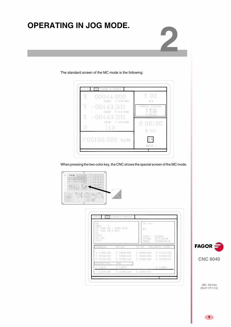
The standard screen of the MC mode is the following:
When pressing the two-color key, the CNC shows the special screen of the MC mode.

Operating manual
CNC 8040
2.
OP
ER
AT
ING
IN J
OG
MO
DE
.
Intr
oduc
tion.
·MC· OPTION(SOFT V11.1X)
10
2.1 Introduction.
2.1.1 Standard screen of the MC mode.
The standard screen of the MC mode offers the following data:
1. Clock.
2. This window may show the following data:
SBK when “single block” execution mode is selected.
DNC when the DNC mode is active.
P..... number of the program currently selected.
Message "In position" - "Execution" - "Interrupted" - "RESET".
PLC messages.
3. This window shows the CNC messages.
4. This window may show the following data:
X, Y, Z coordinates of the axes.
In small characters, the axis coordinates referred to machine reference zero.These values are useful when letting the user define a tool change point (see zone6) The CNC shows this data when text 33 of program 999997 has not beendefined.
The coordinates of the auxiliary axes that are defined.
The real spindle rpm.
5. The information shown in this window depends on the position of the left switch.
In all cases, it shows the axis feedrate "F" currently selected and the % of F beingapplied.
When feed-hold is active, the color of the feedrate value changes.

Operating manual
CNC 8040
OP
ER
AT
ING
IN J
OG
MO
DE
.
Intr
oduc
tion.
2.
·MC· OPTION(SOFT V11.1X)
11
Here are all the possible cases.
6. This window shows, in large characters, the selected tool number "T" and, in smallcharacters, the "D" offset associated with the tool. If the tool number and the offsetnumber are the same, the CNC will not show the “D” value.
This window also shows the coordinates of the tool change point referred tomachine reference zero. The CNC does not show this window when text 47 ofprogram 999997 has not been defined.
7. This window shows everything related to the spindle:
The real spindle speed "S".
The spindle status. It is represented with an icon and may be turning clockwise,counterclockwise or stopped.
The % of spindle speed being applied.
The active spindle speed gear (range). The CNC does not show this data whentext 28 of program 999997 has not been defined.
8. When accessing a work cycle, this window shows the help text associated withthe selected icon.
That help text must be defined in program P999997 and edited in the desiredlanguage. See chapter "1 General parameters".
9. Reserved.
Displaying the active PLC messages.
At the screen, press [+] of the alphanumeric keyboard, the CNC shows a window withall the active PLC messages. Besides, this window is also displayed whenever thereis a program in execution.
The [ ] [ ] [PG UP] [PG DW] keys are used to move around the messages. The[ESC] key is used to close the window.
The window is only displayed when there are more than one active message.

Operating manual
CNC 8040
2.
OP
ER
AT
ING
IN J
OG
MO
DE
.
Intr
oduc
tion.
·MC· OPTION(SOFT V11.1X)
12
2.1.2 Special screen of the MC mode.
The special screen of the MC mode offers the following data:
1. Clock.
2. This window may show the following data:
SBK when “single block” execution mode is selected.
DNC when the DNC mode is active.
P..... number of the program currently selected.
Message "In position" - "Execution" - "Interrupted" - "RESET".
PLC messages.
3. This window shows the CNC messages.
4. This window shows the lines of the program currently selected.
5. The X, Y, Z axes have the following fields:
The spindle (S) has the following fields:
The auxiliary axes only show the real current position of the axis.
COMANDO It indicates the programmed coordinate orposition that the axis must reach.
ACTUAL It indicates the actual (current) position of theaxis.
REST It indicates the distance which is left to run to theprogrammed coordinate.
FOLLOWING ERROR Difference between the theoretical value andthe real value of the position.
THEORETICAL Programmed theoretical S speed.
RPM Speed in rpm.
M/MIN Speed in meters per minute.
FOLLOWING ERROR When working with spindle orientation (M19), itindicates the difference between the theoreticaland the real speeds.

Operating manual
CNC 8040
OP
ER
AT
ING
IN J
OG
MO
DE
.
Intr
oduc
tion.
2.
·MC· OPTION(SOFT V11.1X)
13
6. This window shows the status of the "G" functions and the auxiliary "M" functionsthat are active. Likewise, it shows the value of the variables.
7. Reserved.
8. Reserved.
Displaying the active PLC messages.
At the screen, press [+] of the alphanumeric keyboard, the CNC shows a window withall the active PLC messages. Besides, this window is also displayed whenever thereis a program in execution.
The [ ] [ ] [PG UP] [PG DW] keys are used to move around the messages. The[ESC] key is used to close the window.
The window is only displayed when there are more than one active message.
PARTC It indicates the number of consecutive parts executed with thesame part-program.
Every time a new program is selected, this variable is reset to "0".
CYTIME It indicates the time elapsed while executing the part. It is given in"hours : minutes : seconds : hundredths of a second".
Every time a part-program execution starts, even when repetitive,this variable is reset to "0".
TIMER It indicates the count of the timer enabled by PLC. It is given in"hours : minutes : seconds".

Operating manual
CNC 8040
2.
OP
ER
AT
ING
IN J
OG
MO
DE
.
Intr
oduc
tion.
·MC· OPTION(SOFT V11.1X)
14
2.1.3 Standard screen of the MC mode. Configuration of two and halfaxes.
A two-and-a-half-axis configuration is a milling machine where the X and Y axes aremotorized and the Z axis is set as a DRO axis (display only). In this configuration,the Z axis is moved manually.
The CNC interface for this type of configuration looks like this.
Editing and execution.
The cycles are edited, stored and simulated just like a 3-axis configuration.
The most significant different lays in the execution because the operator must movethe Z axis by hand. The standard screen shows the operations to be carried out bythe operator. In each case, it shows the status of the Z axis and the various actionsto be executed by the operator.
• Move Z up (it shows an icon next to the final Z coordinate).
The operator must move the axis up manually. When the Z axis is in position, themessage will change.
• Move Z down (it shows an icon next to the final Z coordinate).
The operator must move the axis down manually. When the Z axis is in position,the message will change.
• Press CYCLE START.
The operator must press [CYCLE START] to begin the X-Y movement inautomatic.
• Moving in X-Y.
The machine is moving in X-Y. When a Z axis move is required, the machine willstop and it will request the operator's intervention.
• Tool inspection.
It went into tool inspection.

Operating manual
CNC 8040
OP
ER
AT
ING
IN J
OG
MO
DE
.
Intr
oduc
tion.
2.
·MC· OPTION(SOFT V11.1X)
15
Canned cycles.
Not all the cycles can be applied to a two-and-a-half-axis configuration. The followingcycles are permitted. In some of these cycles, some data has been eliminated toadapt them to the two-and-a-half-axis configuration. This data referred to operationsof the Z axis.
• Positioning 1 and 2.
• Profile milling and profile 1 milling.
• Surface milling.
• Slot milling.
• 2D profile pocket.
• Rectangular and circular boss.
• Simple, rectangular and circular pocket 1 and 2.
• Center punching.
• Drilling 1.
• Reaming.
• Boring 1 and 2.
• Multiple positioning, point to point, linear, in arc 1 and 2, in grid and rectangularpatterns.

Operating manual
CNC 8040
2.
OP
ER
AT
ING
IN J
OG
MO
DE
.
Intr
oduc
tion.
·MC· OPTION(SOFT V11.1X)
16
2.1.4 Selecting a program for simulation or execution.
When selecting a part-program or operation saved as part of a part-program forsimulation or execution, the CNC selects that part-program and shows it highlightednext to the green "start" symbol in the top center window.
When the top center window shows the part-program selected next to the green"start" symbol, the CNC acts as follows:
• If [START] is pressed, the CNC executes the part-program that is selected.
• If [CLEAR] is pressed, the CNC de-selects the part-program and removes it fromthe top center window.

Operating manual
CNC 8040
OP
ER
AT
ING
IN J
OG
MO
DE
.
Axi
s co
ntro
l.
2.
·MC· OPTION(SOFT V11.1X)
17
2.2 Axis control.
2.2.1 Work units.
When accessing the MC mode, the CNC assumes the work units “mm or inches”,“mm/min. or mm/rev”, etc. selected by machine parameter.
To modify those values, access the M mode and change the corresponding machineparameter.
2.2.2 Coordinate preset.
The coordinates must be preset on one axis at a time proceeding as follows:
1. Press the key of the desired axis, [X], [Y] or [Z].
The CNC will highlight the coordinate of that axis indicating that it is selected.
2. Key in the value to preset the axis.
To quit the preset mode, press [ESC].
3. Press [ENTER] for the CNC to assume that value as the new value for the point.
The CNC requests confirmation of the command. Press the [ENTER] to confirmit or [ESC] to quit the preset mode.
2.2.3 Managing the axis feedrate (F).
To set a particular axis feedrate value, proceed as follows:
1. Press the [F] key.
The CNC will highlight the current value that it is selected.
2. Key in the desired new feedrate value.
To quit the preset selection mode, press [ESC].
3. Press [START] for the CNC to assume that value as the new value for axisfeedrate.

Operating manual
CNC 8040
2.
OP
ER
AT
ING
IN J
OG
MO
DE
.
Hom
e se
arch
.
·MC· OPTION(SOFT V11.1X)
18
2.3 Home search.
Home search may be done in 2 ways:
• Homing all the axes.
• Homing a single axis.
Homing all the axes.
To home all the axes, press [ZERO].
The CNC requests confirmation of the command (text 48 of program 999997). Press[START], the CNC will execute the home search subroutine defined by the OEM ingeneral machine parameters P34 (REFPSUB).
Homing a single axis.
To home a single axis, press the key of the desired axis and the key for home search.
In either case, the CNC requests confirmation of the command (text 48 of program999997).
After searching home this way, the CNC will maintain the part zero or zerooffset active at the time.
A home search subroutine (general machine parameter P34 other than 0)must be defined when using this method. Otherwise, the CNC will display thecorresponding error.
i
It homes the X axis.
It homes the Y axis.
It homes the Z axis.
After searching home this way, the CNC will not maintain the part zero or zerooffset active at the time and assumes the machine reference zero as the newpart zero.
i

Operating manual
CNC 8040
OP
ER
AT
ING
IN J
OG
MO
DE
.
Zer
o of
fset
tabl
e.
2.
·MC· OPTION(SOFT V11.1X)
19
2.4 Zero offset table.
It is possible to manage the zero offset table (G54-G59) from the conversationalmode. This table contains the same values as that of the conversational mode.
Press the [ZERO] key to access the zero offset table as well as to get out of it. Thezero offset table may be accessed in the following ways.
• From the standard screen, as long as no axis is selected. The CNC will requestconfirmation of the command.
• From ISO mode, when the "zero offsets and presets" cycle is selected.
The zero offset table looks like this. It shows all the offsets, PLC offset included, andtheir value in each axis.
When scrolling the focus through the table, the elements appear in different colorsas follows.
How to edit the table data.
The following operations are possible in the zero offset table. Press [ENTER] tovalidate any changes.
• Editing a zero offset.
It is edited one axis at a time. Select a data with the focus and edit its value. Ifthe focus is placed on a zero offset (G54-G59), the editing begins on the first axisof that zero offset.
• Load the active zero offset into the table.
Place the focus on the zero offset to be defined (G54-G59) and press the[RECALL] key. The active preset is saved in the selected zero offset.
If instead of placing the focus on a zero offset, it is placed on one of the axes, onlythat axis will be affected.
Color Meaning
Green background.
Text in white.
The real value of the table and the value shown on thescreen are the same.
Red background.
White text.
The real value of the table and the value shown on thescreen are NOT the same.
The value on the table has been changed, but it has notbeen validated. Press [ENTER] to validate the change.
Blue background. The zero offset is active.There may be two active zero zero offsets at the sametime, one absolute (G54-G57) and another oneincremental (G58-G59).

Operating manual
CNC 8040
2.
OP
ER
AT
ING
IN J
OG
MO
DE
.
Zer
o of
fset
tabl
e.
·MC· OPTION(SOFT V11.1X)
20
• Deleting a zero offset.
Place the focus on the zero offset to be delete (G54-G59) and press the [CLEAR]key. All the axes of that zero offset are reset to zero.
If instead of placing the focus on a zero offset, it is placed on one of the axes, onlythat axis will be affected.

Operating manual
CNC 8040
OP
ER
AT
ING
IN J
OG
MO
DE
.
Jog.
2.
·MC· OPTION(SOFT V11.1X)
21
2.5 Jog.
When making a move in manual, both in jog and with handwheels, the moving axisappears in reverse video.
• With gantry axes, only the master axis is highlighted.
• With a path handwheel, no axis is highlighted; but it is in path-jog.
2.5.1 Moving an axis to a coordinate.
The movements of axes to a particular coordinate are made one at a time as follows.
2.5.2 Incremental move.
Turn the JOG switch to one of the JOG positions.
The incremental movement must be made one axis at a time. To do that, press theJOG keys for the direction of the axis to be jogged.
Every time a key is pressed, the corresponding axis moves the amount set by theswitch. This movement is made at the selected feedrate (F).
[target coordinate]
[target coordinate]
[target coordinate]
Switch position Distance
1 0.001 mm or 0.0001 inches
10 0.010 mm or 0.0010 inches
100 0.100 mm or 0.0100 inches
1000 1.000 mm or 0.1000 inches
10000 10.000 mm or 1.0000 inches

Operating manual
CNC 8040
2.
OP
ER
AT
ING
IN J
OG
MO
DE
.
Jog.
·MC· OPTION(SOFT V11.1X)
22
2.5.3 Continuous movement.
Place the movement selector in the continuous-jog position and select at the feedrateoverride switch (FEED) the percentage (0% to 120%) of the feedrate to be applied.
The continuous jog must be made one axis at a time. To do that, press the JOG keysfor the direction of the axis to be jogged.
The axis moves at a feedrate equal to the selected percentage (0% to 120%) offeedrate "F".
Depending on the status of the general logic input "LATCHMAN", the movement willbe carried out as follows:
• If the PLC sets this mark low, the axis will be jogged while pressing thecorresponding Jog key.
• If the PLC sets this mark high, the axes will start moving from the moment theJOG key is pressed until the same is pressed again, or another JOG key ispressed. In this case, the movement will be transferred to that indicated by thenew key.
The following cases are possible when working with "F" in mm/rev:
• The spindle is running.
• The spindle is stopped, but a spindle speed S has been selected.
• The spindle is stopped and no spindle speed S has been selected.
The spindle is running.
The spindle is stopped, but a spindle speed S has been selected.
The spindle is stopped and no spindle speed S has been selected.
If while jogging an axis, the rapid key is pressed, the axis will move at the maximumfeedrate possible, set by axis machine parameter "G00FEED". This feedrate will beapplied while that key is kept pressed and the previous feedrate will be restored whenthat key is released.
The CNC moves the axes at the programmed F.
The CNC calculates the feedrate F in mm/min for the theoretical S and moves theaxis.
For example if "F 2.000" and "S 500":
F (mm/min) = F (mm/rev) x S (mm/rev) = 2 x 500 = 1000 mm/min.
The axis moves at a feedrate of 1000 mm/min.
If F = 0, the CNC moves the axes in rapid.
If F is other than 0, the axes can only be moved by pressing the rapid key and anaxis key. The CNC moves the axis in rapid.

Operating manual
CNC 8040
OP
ER
AT
ING
IN J
OG
MO
DE
.
Jog.
2.
·MC· OPTION(SOFT V11.1X)
23
2.5.4 Path-jog.
The "path jog" mode acts when the switch is in one of the continuous or incrementaljog positions. This feature may be used to act upon the jog keys of an axis to moveboth axes of the plane at the same time for chamfering (straight sections) androunding (curved sections). The CNC assumes as "Path jog" the keys associated withthe X axis.
While in jog mode and having selected path-jog, the CNC shows the followinginformation:
For a linear movement (top figure), the path angle must be defined and for an arc(bottom figure), the center coordinates must be indicated. To define these variables,press the [F] key and then one of these keys: [ ] [ ] [ ] [ ].
Operation in path-jog mode
The "path jog" mode is only available with the X axis keys. When pressing one of thekeys associated with the X axis, the CNC behaves as follows:
The rest of the jog keys always work in the same way, whether "path jog" is on oroff. The rest of the keys move only the axis and in the indicated direction.
The movements in path-jog may be aborted by pressing the [STOP] key or settingthe jog switch to one of the handwheel positions.
This feature must be managed from the PLC. This feature is usually activatedand deactivated by means of an external push-button or a key configured forthat purpose, as well as the selection of the type of path.
i
The next example uses the [O2] key to activate and deactivate the path-jog modeand the [O3] key to indicate the type of movement.
• Activate / deactivate the path-jog mode.
DFU B29 R561 = CPL M5054
• It selects the type of movement, straight section or arc section.
DFU B31 R561 = CPL M5053
Switch position Path-jog Type of movement
Continuous jog OFF Only the axis and in the indicated direction
ON Both axes in the indicated direction and alongthe indicated path
Incremental jog OFF Only the axis, the selected distance and in theindicated direction
ON Both axes, the selected distance and in theindicated direction, but along the indicated path
Handwheel It ignores the keys.

Operating manual
CNC 8040
2.
OP
ER
AT
ING
IN J
OG
MO
DE
.
Jog.
·MC· OPTION(SOFT V11.1X)
24
Considerations about the jog movements
This mode assumes as axis feedrate the one selected in jog mode and it will also beaffected by the feedrate override switch. If F0 is selected, it assumes the oneindicated by machine parameter “JOGFEED (P43)”. This mode ignores the rapid jogkey.
Path-jog movements respect the travel limits and the work zones.

Operating manual
CNC 8040
OP
ER
AT
ING
IN J
OG
MO
DE
.
Jog.
2.
·MC· OPTION(SOFT V11.1X)
25
2.5.5 Movement with an electronic handwheel.
This option may be used to govern the movements of the machine using an electronichandwheel. To do that, turn the left switch to any of the handwheel positions.
The positions available are 1, 10 and 100; they indicate the multiplying factor beingapplied besides the internal x4 to the feedback pulses supplied by the electronichandwheel.
The machine has an electronic handwheel.
Once the desired switch position has been selected, press one of the JOG keys forthe axis to be jogged. The bottom of the screen shows the selected axis in smallcharacters and next to the handwheel symbol.
When using a FAGOR handwheel with an axis selector button, the axis may beselected as follows:
• Push the button on the back of the handwheel. The CNC select the first axis andit highlights it.
• When pressing the button again, the CNC selects the next axis and so on in arotary fashion.
• To deselect the axis, hold the button pressed for more than 2 seconds.
Once the axis has been selected, it will move as the handwheel is being turned andin the direction indicated by it.
The machine has two or three electronic handwheels.
Each axis will move as the corresponding handwheel is being turned according tothe switch position and in the direction indicated by it.
When the machine has a general handwheel and individual handwheels (associatedwith each axis of the machine), the individual handwheels have the highest priority;i.e. when moving an individual handwheel, the CNC will ignore the generalhandwheel.
Switch position Distance per turn
1 0.100 mm or 0.0100 inches
10 1.000 mm or 0.1000 inches
100 10.000 mm or 1.0000 inches
It may happen that depending on the turning speed and the selector switchposition, the CNC be demanded a faster feedrate than the maximum allowed(axis machine parameter "G00FEED"). The CNC will move the axis theindicated distance but at the maximum feedrate allowed.
i
Operating manual
CNC 8040
2.
OP
ER
AT
ING
IN J
OG
MO
DE
.
Jog.
·MC· OPTION(SOFT V11.1X)
26
2.5.6 Feed handwheel.
Usually, when making a part for the first time, the machine feedrate is controlled bymeans of the feedrate override switch.
From this version on, it is also possible to use the machine handwheels to controlthat feedrate. This way, the machining feedrate will depend on how fast thehandwheel is turned.
The following CNC variables return the number of pulses the handwheel has turned.
HANPF Provides the number of pulses of the 1st handwheel.
HANPS Provides the number of pulses of the 2nd handwheel.
HANPT Provides the number of pulses of the 3rd handwheel.
HANPFO Provides the number of pulses of the 4th handwheel.
This feature must be managed from the PLC. This feature is usually activatedand deactivated by means of an external push-button or a key configured forthat purpose.
i

Operating manual
CNC 8040
OP
ER
AT
ING
IN J
OG
MO
DE
.
Jog.
2.
·MC· OPTION(SOFT V11.1X)
27
2.5.7 Path-handwheel.
The "path handwheel" mode acts when the switch is in one of the handwheelpositions. With this feature, it is possible to jog two axes of the plane at the same timealong a linear path (chamfer) or circular path (rounding) with a single handwheel. TheCNC assumes as the path handwheel the general handwheel or, when this one ismissing, the one associated with the X axis.
While in handwheel mode and having selected path-handwheel, the CNC shows thefollowing information:
For a linear movement (top figure), the path angle must be defined and for an arc(bottom figure), the center coordinates must be indicated. To define these variables,press the [F] key and then one of these keys: [ ] [ ] [ ] [ ].
Operation in path-handwheel mode.
When selecting the path handwheel mode, the CNC behaves as follows.
• If there is a general handwheel, it will be the one working in path handwheel mode.The individual handwheels, if any, will remain associated with the correspondingaxes.
• If there is no general handwheel, the individual handwheel associated with theX axis then works in path-handwheel mode.
The movements in path-handwheel may be aborted by pressing the [STOP] key orsetting the jog switch to one of the continuous or incremental positions.
This feature must be managed from the PLC. This feature is usually activatedand deactivated by means of an external push-button or a key configured forthat purpose, as well as the selection of the type of path.
i
The next example uses the [O2] key to activate and deactivate the path-handwheelmode and the [O3] key to indicate the type of movement.
• Activate / deactivate the path-handwheel mode.
DFU B29 R561 = CPL M5054
• It selects the type of movement, straight section or arc section.
DFU B31 R561 = CPL M5053

Operating manual
CNC 8040
2.
OP
ER
AT
ING
IN J
OG
MO
DE
.
Too
l con
trol
.
·MC· OPTION(SOFT V11.1X)
28
2.6 Tool control.
The standard screen of the MC mode offers the following tool data.
This window displays the following information:
• In large characters, the tool "T" number currently selected.
• The "D" offset number associated with the tool.
• The position values of the tool change point. The CNC does not show this windowwhen text 47 of program 999997 has not been defined.
To select another tool, follow these steps:
1. Press the [T] key.
The CNC highlights the tool number.
2. Key in the number of the tool to be selected.
To quit the preset selection mode, press [ESC].
3. Press [START] for the CNC to select the new tool.
The CNC will manage the tool change.

Operating manual
CNC 8040
OP
ER
AT
ING
IN J
OG
MO
DE
.
Too
l con
trol
.
2.
·MC· OPTION(SOFT V11.1X)
29
2.6.1 Tool change.
Depending on the type of tool changer, the following options are possible:
• Machine with automatic tool changer.
• Machine with manual tool changer.
In either case, the CNC acts as follows:
• The CNC executes the subroutine associated with the tool change (generalmachine parameter P60 "TOOLSUB").
• The CNC sends to the PLC all the necessary information for it to manage the toolchange.
• The CNC assumes the new tool values (offsets, geometry, etc).
Example of how to manage a manual tool changer.
• Subroutine 55 is defined as the subroutine associated with the tools.
General machine parameter P60 "TOOLSUB" = 55.
The subroutine associated with the tools may contain the following information:
• The tool is selected after executing the subroutine.
General machine parameter P71 "TAFTERS" = YES.
• The movement to the change point only takes place when executing an operationor cycle of the MC mode.
• Once the subroutine is completed, the CNC executes function T??, sends to thePLC all the necessary information for it to manage the tool change and assumesthe new tool values (offsets, geometry, etc.).
( SUB 55)
(P100 = NBTOOL)
; Assigns the requested tool number to P100.
(P101 = MS3)
; If spindle counterclockwise P102=1.
G0 G53... XP?? YP?? ZP??; Movement to the tool change point.
M5
; Spindle stop.
(MSG "SELECT T?P100 AND PRESS START")
; Message to select the tool change.
M0; Stop the program stop and wait for START to be pressed.
(MSG "")
; Deletes previous message.
(IF P102 EQ 1 GOTO N10)
; Restores the spindle turning direction.
(IF P101 EQ 0 RET)
M3
(RET)
N10 M4
(RET)
When a cycle has been selected (CYCEXE other than 0)
The program is being executed (OPMODA bit 0 = 1).
Operating manual
CNC 8040
2.
OP
ER
AT
ING
IN J
OG
MO
DE
.
Too
l con
trol
.
·MC· OPTION(SOFT V11.1X)
30
Managing a machining center.
When having a machining center, general machine parameter "TOFFM06 (P28) =Yes", the CNC acts as follows:
If the execution of an operation or cycle involves a tool change, the CNC:
• Selects the desired tool in the magazine.
• Executes the subroutine associated with the tool (general machine parameter"TOOLSUB (P60)".
• Executes function M06 to make the tool change.
When selecting a new tool in jog mode or working in M mode, the CNC only selectsthe tool in the magazine and executes the associated subroutine. The user mustexecute function M06, either by programming a block in ISO mode or setting the PLCso the M06 is executed when pressing a particular key.
The next example uses the [O4] key: DFU B2 R562 = CNCEX1 (M06, M1)
In machining centers, the subroutine associated with the tool must not havethe M06 function.i

Operating manual
CNC 8040
OP
ER
AT
ING
IN J
OG
MO
DE
.
Too
l con
trol
.
2.
·MC· OPTION(SOFT V11.1X)
31
2.6.2 Variable tool change point.
If the manufacturer so wishes, he can let the user define the tool change point everytime. Obviously, this feature depends on the type of machine and type of tool changer.
This feature may be used to change the tool next to the part, thus avoiding movementsto a tool change point located far away from it.
To do this:
• Define the text 47 of program 999997 so the CNC requests the X, Y, Z coordinatesof the tool change point.
For example: ;47 $CHANGE POSITION
These coordinates must be referred to machine zero point, so the zero offsetsdo not affect the tool change point. Therefore, the CNC can show, next to the X,Y, Z coordinates and in small characters, the coordinates of the axes referred tomachine reference zero.
• Text 33 of program 999997 must be defined so the CNC shows the coordinatesof the axes referred to machine reference zero.
For example: ;33 $MACHINE ZERO
Since the operator can change the tool change point at any time, the subroutineassociated with the tools must consider those values. Arithmetic parameters P290,P291 and P292 contain the values set by the operator as tool change position in X,Y and Z respectively.
In subroutine 55 of the previous section, the line setting the movement to the toolchange point must be modified:
Where it says:
G0 G53 XP??? YP??? ZP??? ; Movement to the tool change point.
It must say:
G0 G53 XP290 YP291 ZP292 ;User-defined movement to the change point.
Define the coordinates of the tool change point (X, Y, Z).
1. Press the [T] key to select the "T" field.
2. Then press the [X], [Y] or [Z] key of the desired axis or the [ ] [ ] [ ] [ ] keys.
3. After placing the cursor on the coordinates of the axis to be defined, define thedesired values.
After placing the cursor on the coordinates of the axes to be defined, the value isentered in one of the following ways.
• Entering the value manually. Key in the desired value and press [ENTER].
• Assign the current machine position.
Arithmetic parameter P290.
Change position in X.
Arithmetic parameter P291.
Change position in Y.
Arithmetic parameter P292.
Change position in Z.

Operating manual
CNC 8040
2.
OP
ER
AT
ING
IN J
OG
MO
DE
.
Too
l con
trol
.
·MC· OPTION(SOFT V11.1X)
32
Jog the axis with the handwheel or the JOG keys up to the desired point. Press[RECALL] so the selected data assumes the value shown in the top right windowand press [ENTER].
The top right window shows the tool position at all times.

Operating manual
CNC 8040
OP
ER
AT
ING
IN J
OG
MO
DE
.
Too
l cal
ibra
tion.
2.
·MC· OPTION(SOFT V11.1X)
33
2.7 Tool calibration.
The calibration mode can have three editing levels. The second and third levels willonly be available when using a table-top probe installed on the machine.
What can be done in tool calibration mode.
The data that may be modified from the calibration cycles depend on when this modeis accessed. The following limitations must be borne in mind when accessing the toolcalibration mode with a program in execution or from tool inspection.
Without a program in execution nor in tool inspection.
When editing the active tool, it is possible:
• Modify all the data.
• Change the active tool (T ?? + [START]).
When NOT editing the active tool, it is possible:
• Modify all the data except the part dimensions.
• Change the active tool (T ?? + [START]).
Program in execution or interrupted.
When editing the active tool, it is possible:
• To modify the I and K data.
• Select another tool (T?? + [RECALL]) and modify the I and K data.
When NOT editing the active tool, it is possible:
• To modify the I, K and D data.
• Select another tool (T?? + [RECALL]) and modify the I, K and D data.
Program in tool inspection.
When editing the active tool, it is possible:
• To modify the I and K data.
• Select another tool (T?? + [RECALL]) and modify the I and K data.
• Change the active tool (T ?? + [START]).
When NOT editing the active tool, it is possible:
• To modify the I, K and D data.
• Select another tool (T?? + [RECALL]) and modify the I, K and D data.
• Change the active tool (T ?? + [START]).
This mode may be used to define the tools and calibrate them. The tools may becalibrated with or without using a probe.
This mode is also available while executing a program and during tool inspection.
Each level has its own screen and the main window of the cycle indicates, with tabs,the available levels and which one is selected. To change levels, use the [LEVELCYCLE] key or the [page up] and [page down] keys to scroll up and down throughthe various levels.

Operating manual
CNC 8040
2.
OP
ER
AT
ING
IN J
OG
MO
DE
.
Too
l cal
ibra
tion.
·MC· OPTION(SOFT V11.1X)
34
2.7.1 Define the tool in the tool table (level 1).
When accessing this level, the CNC shows the following screen.
1. Indicating the selected work mode: "Tool calibration".
2. Help graphics for calibrating the tool.
3. Window for tool calibration.
4. Current machine status.
Real X Y Z coordinates, real axis feedrate F, real spindle speed S and currentlyselected tool T.
5. Tool number and associated offset.
6. Length and offset values defined in the tool offset table for this tool.
7. Nominal life, real life, family and status of the tool defined in the tool table.
Define the tool data.
Proceed as follows to define a tool in the tool table:
Select the number of the tool to be defined.
1. Press the [T] key to select the "T" field.
2. Key in the desired tool number and press [RECALL].
If the tool is defined, the CNC will show the values stored in the table. If the toolis not defined, the CNC assigns an offset with the same number to it and all thedata is reset to 0.
Select the number of the offset tool to be associated with this tool.
1. The "D" field must be selected. If it is not, use the [ ] [ ] [ ] [ ] keys.
2. Key in the desired offset number to be associated with the tool and press[ENTER].
Define the tool dimensions.
The data for the tool is the following.
Even if the tool length (L) is known, it is recommended to measure it. See "2.7.2 Toolcalibration without a probe (level 1)." on page 36.
Once it is measured, the CNC updates the L and K fields. The CNC (R+I) assumesas the real radius and (L+K) as the real length of the tool.
R Radius.
I Radius wear offset.
L Length.
K Length wear offset.

Operating manual
CNC 8040
OP
ER
AT
ING
IN J
OG
MO
DE
.
Too
l cal
ibra
tion.
2.
·MC· OPTION(SOFT V11.1X)
35
To define these values, select the corresponding field with the [ ] [ ] [ ] [ ] keys,key in the desired value and press [ENTER].
Define the rest of the data related to the tool
Nominal life.
Machining time (in minutes) or the number of operations that that tool can carryout.
Real life.
Time it spends machining or number of operations carried out.
Family code.
It is used with an automatic tool changer.
0 ... 199 normal tools.
200 ... 255 special tools.
When requesting a new worn-out tool ("real life" greater than "nominal life"), theCNC will select the next tool of the same family, instead.
Tool status.
They are 2 fields for internal CNC data. They cannot be modified.
N = Normal (family 0-199).
S = Special (family 200-255).
A = Available
E = Expired ("real life" greater than "nominal life").
R = Rejected by the PLC.
To define these values, select the corresponding field with the [ ] [ ] [ ] [ ]keys, key in the desired value and press [ENTER].
Nominal life.
Real life.
Family code.Tool status.

Operating manual
CNC 8040
2.
OP
ER
AT
ING
IN J
OG
MO
DE
.
Too
l cal
ibra
tion.
·MC· OPTION(SOFT V11.1X)
36
2.7.2 Tool calibration without a probe (level 1).
Before measuring the tool, it must be defined in the tool table. See "2.7.1 Define thetool in the tool table (level 1)." on page 34.
There are 2 ways to calibrate a tool.
• When having a tool setting table.
Use the window that shows the tool dimensions to define that data.
• When not having any measuring device.
The measurements will be taken with the CNC. Use the window for toolcalibration.
Define the tool length or modify the length offsets.
This window shows the dimensions assigned to the selected tool.
The R and L data indicate the tool dimensions, radius and length. I and K indicatethe offset the CNC must apply to compensate for tool wear.
The CNC adds the value of the "I" offset to the radius (R) and the value of the "K"offset to the length (L) to calculate the real dimensions (R+I, L+K) that must be used.
• Every time the radius or length value is defined, the CNC sets the "I" and "K" fieldsto 0 respectively.
• The "I" and "K" data are accumulative. In other words, if the "I" has a value of 0.20and the value of 0.05 is entered, the CNC assigns the value of 0.25 (0,20+0,05)to the "I" field.
• If one sets I=0 or K=0, they are both reset to 0.
To change one of these values, select the corresponding field, key in the desiredvalue and press [ENTER].
Tool calibration.
The right window shows the tool dimensions and the lower left window shows thenecessary data to calibrate it.
To access the calibration window, (lower left window) and, thus calibrate the tool, thetool must be selected on the machine. If it is not, press the [T] key, key in the desirednumber of the tool to be calibrated and press [START].
Select the lower left window with the [ ] [ ] [ ] [ ] keys Enter the Z coordinate ofthe part to be used in the calibration and press [ENTER].
Tool calibration (only measuring the length).
R Radius.
I Radius wear offset.
L Length.
K Length wear offset.
Operating manual
CNC 8040
OP
ER
AT
ING
IN J
OG
MO
DE
.
Too
l cal
ibra
tion.
2.
·MC· OPTION(SOFT V11.1X)
37
1. Approach the tool to the part and touch it with it.
2. Then, press the keystroke sequence [Z] [ENTER].
The tool has been calibrated. The CNC assigns the corresponding length (L) to it andresets the K offset value to 0. The tool radius (R) must be entered manually.
To calibrate another tool:
1. Select it on the machine.
2. Approach the tool to the part and touch it with it.
3. Then, press the keystroke sequence [Z] [ENTER].
Modifying the tool data while executing a program.
It is possible to modifying the tool values (dimensions and geometry) withoutinterrupting the execution of a program.
To exit this screen, press [ESC].
To do that, press the tool calibration key. The CNC will show the tool calibrationscreen with all the data for the active tool and it will allow modifying its data or of anyother tool.

Operating manual
CNC 8040
2.
OP
ER
AT
ING
IN J
OG
MO
DE
.
Too
l cal
ibra
tion.
·MC· OPTION(SOFT V11.1X)
38
2.7.3 Tool calibration with a probe (level 2).
This calibration level requires the purchase of the right software options purchasedand the use of a table-top probe.
When accessing this level, the CNC shows the following screen.
A. Indicating the selected work mode.
B. Help graphics for calibrating the tool.
C. Current machine status.
D. Tool number and associated offset.
E. Calibration data.
F. Type of operation and wear values.
G. Probe position.
This level may be saved as part of a part-program using the [P.PROG] key orexecuted using the [START] key.
Defining the cycle data.
The following data must be defined. All the data will not always be available; the cyclewill show the necessary data depending on the selected operation.
• Safety distance (Ds), for the probe approach.
• Probing feedrate (F).
• Type of calibration or measurement.
The cycle allows calibrating or measuring the following dimensions; only the toollength along its shaft or on its tip, only the radius or the length and the radius.
• Speed (S) and turning direction of the tool. Select the turning direction oppositeto the cutting direction.
• Number of cutting edges (N) to be measured.
• The probe side to be used (X+ X- Y+ Y-). Only when calibrating or measuring theradius.
• The distance from the tool shaft to the probing point (d). Only when calibratingor measuring the length at one end.
• Distance referred to the theoretical tool tip being probed (h). This parameter maybe very useful with cutters whose bottom is not horizontal.
A
B
C
D
E
F
G

Operating manual
CNC 8040
OP
ER
AT
ING
IN J
OG
MO
DE
.
Too
l cal
ibra
tion.
2.
·MC· OPTION(SOFT V11.1X)
39
Type of operation.
The cycle may be used to do a measurement or a calibration. To select the desiredoperation, position the cursor on the "Measurement / Calibration" field and press thetwo-color key. To take a measurement, define the following data.
Measuring is only available when purchasing the software option: "Tool lifemonitoring".
Probe position.
In this zone, one must indicate whether the cycle assumes the probe position definedin the machine parameters or the position defined in this zone. To select one of them,use the cursor to select the "Machine parameters / Programmable parameters" fieldand press the two-color key.
Kmax Maximum length wear allowed.
Imax Maximum radius wear allowed.
StopChg
Cycle behavior when exceeding the maximum wear allowed. Use the two-color key to select one of them.
The "Stop" option interrupts the execution for the user to select anothertool. With the "Chg" option, the cycle replaces the tool with another oneof the same family.
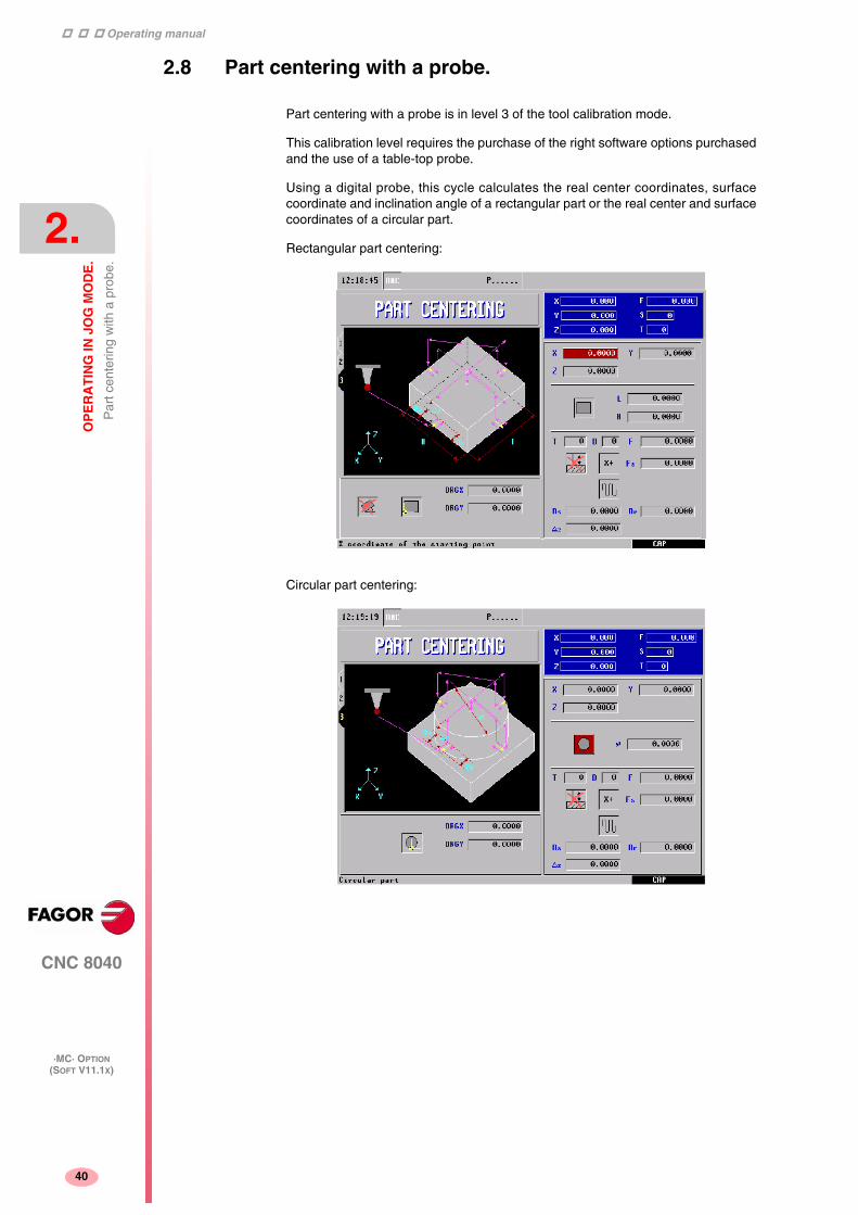
Operating manual
CNC 8040
2.
OP
ER
AT
ING
IN J
OG
MO
DE
.
Par
t cen
terin
g w
ith a
pro
be.
·MC· OPTION(SOFT V11.1X)
40
2.8 Part centering with a probe.
Part centering with a probe is in level 3 of the tool calibration mode.
This calibration level requires the purchase of the right software options purchasedand the use of a table-top probe.
Using a digital probe, this cycle calculates the real center coordinates, surfacecoordinate and inclination angle of a rectangular part or the real center and surfacecoordinates of a circular part.
Rectangular part centering:
Circular part centering:

Operating manual
CNC 8040
OP
ER
AT
ING
IN J
OG
MO
DE
.
Par
t cen
terin
g w
ith a
pro
be.
2.
·MC· OPTION(SOFT V11.1X)
41
Data to be entered:
Icon for selecting the axis and the direction (X+, X-, Y+, Y-) of the first probingmovement.
Icon to select part surface measuring.
Icon to select the type of part to be centered (rectangular or circular).
L, H: Part lengths (length and width if rectangular, diameter if circular).
∆Z: Distance for the probe to go up in Z for probing movements over the part.
Ds: Part approaching distance in part searching probing movements. If notprogrammed, it takes the approach distance left by the operator.
Dr: Withdrawal distance, after the part searching probing movement for measuring.X: X coordinate of the probe position where the first probing move will start. If not
programmed, it will assume the current X position of the probe.Y: Y coordinate of the probe position where the first probing move will start. If not
programmed, it will assume the current Y position of the probe.Z: Z coordinate of the probe position where the first probing move will start. If not
programmed, it will assume the current Z position of the probe.T: Probe's tool number. If not programmed or programmed with a 0 value, it generates
the corresponding error message.D: Tool offset number. If not programmed, it assumes the offset number assigned to
T in the tool table.Fs: Part searching probing feedrate. If not programmed or programmed with a 0 value,
it generates the corresponding error message.F: Probing feedrate for measuring. If not programmed or programmed with a 0 value,
it generates the corresponding error message.Fa: Probe positioning feedrate to the starting points of the part searching probing
movements. If not programmed, it is done in rapid (G0).Icon to preset the coordinates of a part reference point. Its possible values are:
• No preset:
• Preset at the center.
• Preset in each of the 4 corners if a rectangular part or in each of the 4 quadrantsif a circular part.
ORGX: X coordinate of the preset value. If not programmed, it assumes 0.
ORGY: Y coordinate of the preset value. If not programmed, it assumes 0.
ORGZ: If part surface measuring has been selected, Z coordinate of the preset value. If notprogrammed, it assumes 0.
Icon to apply or not the measured coordinate (pattern) rotation. Only for rectangularparts.

Operating manual
CNC 8040
2.
OP
ER
AT
ING
IN J
OG
MO
DE
.
Spi
ndle
con
trol
.
·MC· OPTION(SOFT V11.1X)
42
2.9 Spindle control.
The standard screen of the MC mode offers the following spindle data.
1. Real spindle speed in rpm.
2. Theoretical spindle speed in rpm.
To select another speed, press the [S] key. The CNC highlights the current value.
Enter the new value and press [START]. The CNC assumes that value andrefreshes the real spindle speed.
The maximum spindle speed is saved in the MDISL variable. This variable isupdated (refreshed) when programming function "G92 S" via ISO.
3. Percentage of the theoretical spindle speed being applied.
To modify the percentage (%), press the following keys.
4. Spindle status:
To modify the spindle status, press the following keys:
5. Spindle gear currently selected.
This value cannot be changed when using an automatic gear change.
When not using an automatic tool changer, press the [S] key and then use the[ ] key to highlight the current value. Enter the gear number to be selected andpress [ENTER] or [START].
Spindle clockwise,
Spindle counterclockwise
Spindle stopped.

Operating manual
CNC 8040
OP
ER
AT
ING
IN J
OG
MO
DE
.
Con
trol
ling
the
exte
rnal
dev
ices
.
2.
·MC· OPTION(SOFT V11.1X)
43
2.10 Controlling the external devices.
With this CNC, it is possible to activate and deactivate, via keyboard, up to 6 externaldevices, for example, the coolant.
The machine manufacturer must use the PLC program to activate and deactivate thedevices. The CNC will inform the PLC about the status of each key. Thecorresponding register bit will be set to 1 when the key is pressed and 0 when it isnot pressed.
The register bit for each key is:
The status of the lamp of each key must be controlled by the machine manufacturerthrough the PLC program using the input variables TCLED* indicated in the figure.
Examples:
Coolant control:
DFU B28R561 = CPL TCLED1 = CPL O33
Tailstock control (O1). A number of conditions must be met for activating ordeactivating the tailstock, such as spindle stopped, etc.
DFU B30R561 AND (Rest of conditions) = CPL TCLED2 = CPL O34

Operating manual
CNC 8040
2.
OP
ER
AT
ING
IN J
OG
MO
DE
.
ISO
man
agem
ent.
·MC· OPTION(SOFT V11.1X)
44
2.11 ISO management.
Access to the MDI mode or the ISO mode.
The ISO key may be used to access the MDI mode or the ISO mode.
To access the MDI mode, the CNC must be in jog mode and the ISO key must bepressed. The CNC will show a window at the bottom of the standard (or special)screen.
In this window, it is possible to edit a block in ISO code and then execute it, like inMDI in M mode.
Generating an ISO-coded program
In the conversational mode of the CNC, it is possible to generate an ISO-codedprogram from an operation (cycle) or on a part-program. See "6.5 Graphicrepresentation." on page 118.

45
CNC 8040
·MC· OPTION(SOFT V11.1X)
3WORKING WITH OPERATIONS OR CYCLES.
Use the following CNC keys to select the different machining operations or cycles.
User cycles.
The user cycle is edited like any other standard cycle of the MC mode. Once all therequired data has been defined, the user can simulate or execute the cycle like anyother standard cycle of the MC mode.
Cycles or operations of the CNC.
When pressing any other key, the CNC selects the corresponding standardmachining cycle, changes the display and turns the lamp of the key that has beenpressed (indicating the selected cycle).
Standard machining operations or cycles may be selected with each one of thefollowing keys:
When pressing [PCALL], the CNC shows all the user cycles defined by the machinemanufacturer with the WGDRAW application.
Boring. Surface milling and slot milling.
Reaming. Pocket with profile (2D and 3D).
Tapping. Rectangular and circular boss.
Drilling and center punching. Rectangular and circular pocket.
Profile milling. Positioning.
When the machining operation or cycle has several levels, [LEVEL CYCLE] must bepressed to select the desired cycle level.

Operating manual
CNC 8040
3.
WO
RK
ING
WIT
H O
PE
RA
TIO
NS
OR
CY
CL
ES
.
·MC· OPTION(SOFT V11.1X)
46
Some cycles may be carried out in the tool position or may be associated a multiplepositioning so the cycle may be repeated in several locations. The positioning movesmay be selected with each one of the following keys:
It is possible to combine ISO-coded blocks with standard and/or user cycles to createpart-programs. Chapter "5 Saving programs." describes in detail how to do it andhow to use those programs.
To de-select a cycle and return to the standard screen, press the key for the selectedcycle (the one with the lamp on) or the [ESC] key.
Multiple positioning in several locations.
Multiple positioning in a straight line.
Multiple positioning in an arc.
Multiple positioning in a rectangular pattern.
Multiple positioning in a grid pattern.
The operations or cycles can modify global parameters 150 through 299, bothincluded.i
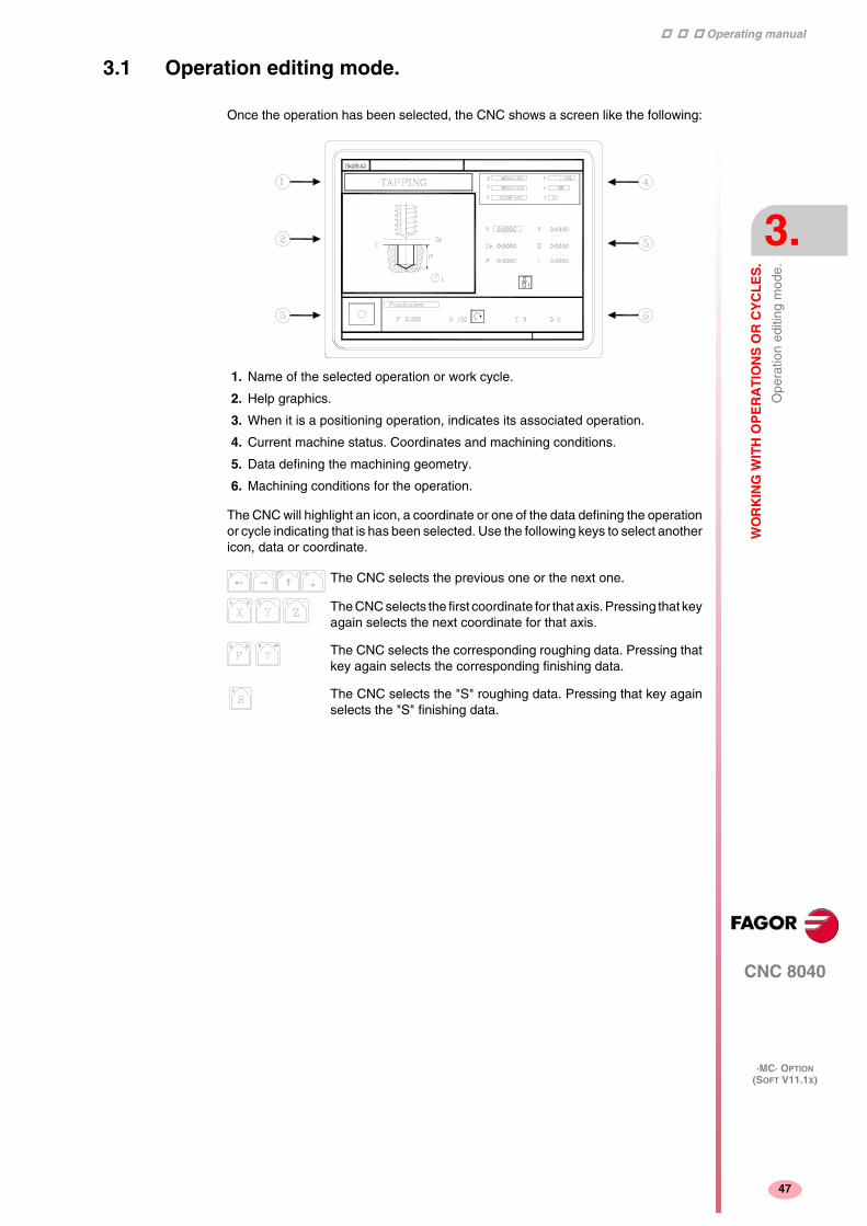
Operating manual
CNC 8040
WO
RK
ING
WIT
H O
PE
RA
TIO
NS
OR
CY
CL
ES
.
Ope
ratio
n ed
iting
mod
e.
3.
·MC· OPTION(SOFT V11.1X)
47
3.1 Operation editing mode.
Once the operation has been selected, the CNC shows a screen like the following:
1. Name of the selected operation or work cycle.
2. Help graphics.
3. When it is a positioning operation, indicates its associated operation.
4. Current machine status. Coordinates and machining conditions.
5. Data defining the machining geometry.
6. Machining conditions for the operation.
The CNC will highlight an icon, a coordinate or one of the data defining the operationor cycle indicating that is has been selected. Use the following keys to select anothericon, data or coordinate.
The CNC selects the previous one or the next one.
The CNC selects the first coordinate for that axis. Pressing that keyagain selects the next coordinate for that axis.
The CNC selects the corresponding roughing data. Pressing thatkey again selects the corresponding finishing data.
The CNC selects the "S" roughing data. Pressing that key againselects the "S" finishing data.

Operating manual
CNC 8040
3.
WO
RK
ING
WIT
H O
PE
RA
TIO
NS
OR
CY
CL
ES
.
Ope
ratio
n ed
iting
mod
e.
·MC· OPTION(SOFT V11.1X)
48
3.1.1 Definition of the machining conditions.
Some operations keep the machining conditions throughout the execution (boring,reaming, etc.). Other operations use some machining conditions for roughing andothers for finishing (pockets, bosses, etc.).
This section describes how to define all this data.
Axis feedrate (F).
Spindle speed (S).
Spindle turning direction
Machining tool (T).
Place the cursor on this data, key in the desired value and press [ENTER].
Press [ESC] to quit the tool calibration mode and return the cycle.
Roughing pass (∆).
Finishing stocks (δ, δz)
Place the cursor on this data, key in the desired value and press [ENTER].
Place the cursor on this data, key in the desired value and press [ENTER].
Place the cursor on this data and press the two-color key.
It is also possible to access the tool calibration mode to check or modify the data forthe selected tool. To do that, place the cursor on the "T" and press the key associatedwith tool calibration.
Place the cursor on this data, key in the desired value and press [ENTER].
Place the cursor on this data, key in the desired value and press [ENTER].
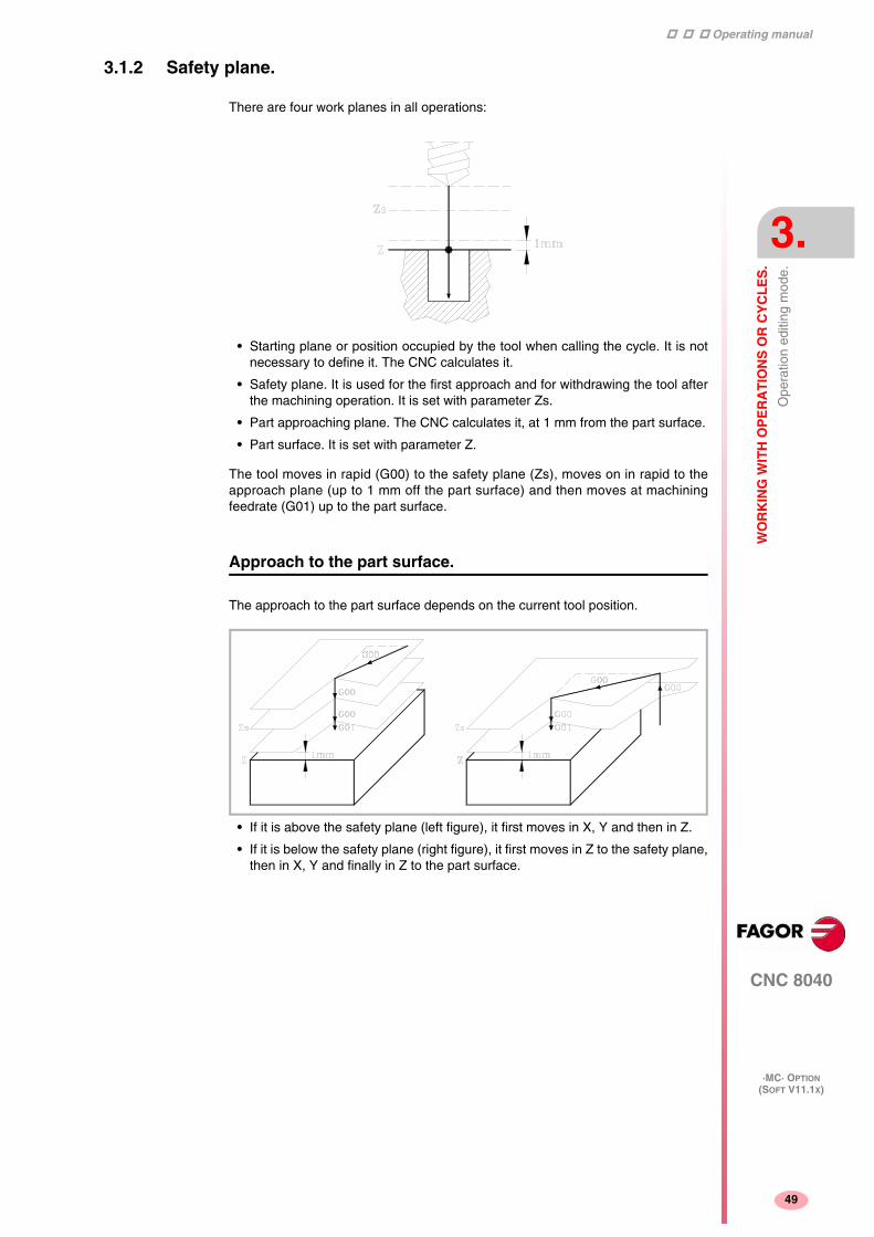
Operating manual
CNC 8040
WO
RK
ING
WIT
H O
PE
RA
TIO
NS
OR
CY
CL
ES
.
Ope
ratio
n ed
iting
mod
e.
3.
·MC· OPTION(SOFT V11.1X)
49
3.1.2 Safety plane.
There are four work planes in all operations:
• Starting plane or position occupied by the tool when calling the cycle. It is notnecessary to define it. The CNC calculates it.
• Safety plane. It is used for the first approach and for withdrawing the tool afterthe machining operation. It is set with parameter Zs.
• Part approaching plane. The CNC calculates it, at 1 mm from the part surface.
• Part surface. It is set with parameter Z.
The tool moves in rapid (G00) to the safety plane (Zs), moves on in rapid to theapproach plane (up to 1 mm off the part surface) and then moves at machiningfeedrate (G01) up to the part surface.
Approach to the part surface.
The approach to the part surface depends on the current tool position.
• If it is above the safety plane (left figure), it first moves in X, Y and then in Z.
• If it is below the safety plane (right figure), it first moves in Z to the safety plane,then in X, Y and finally in Z to the part surface.
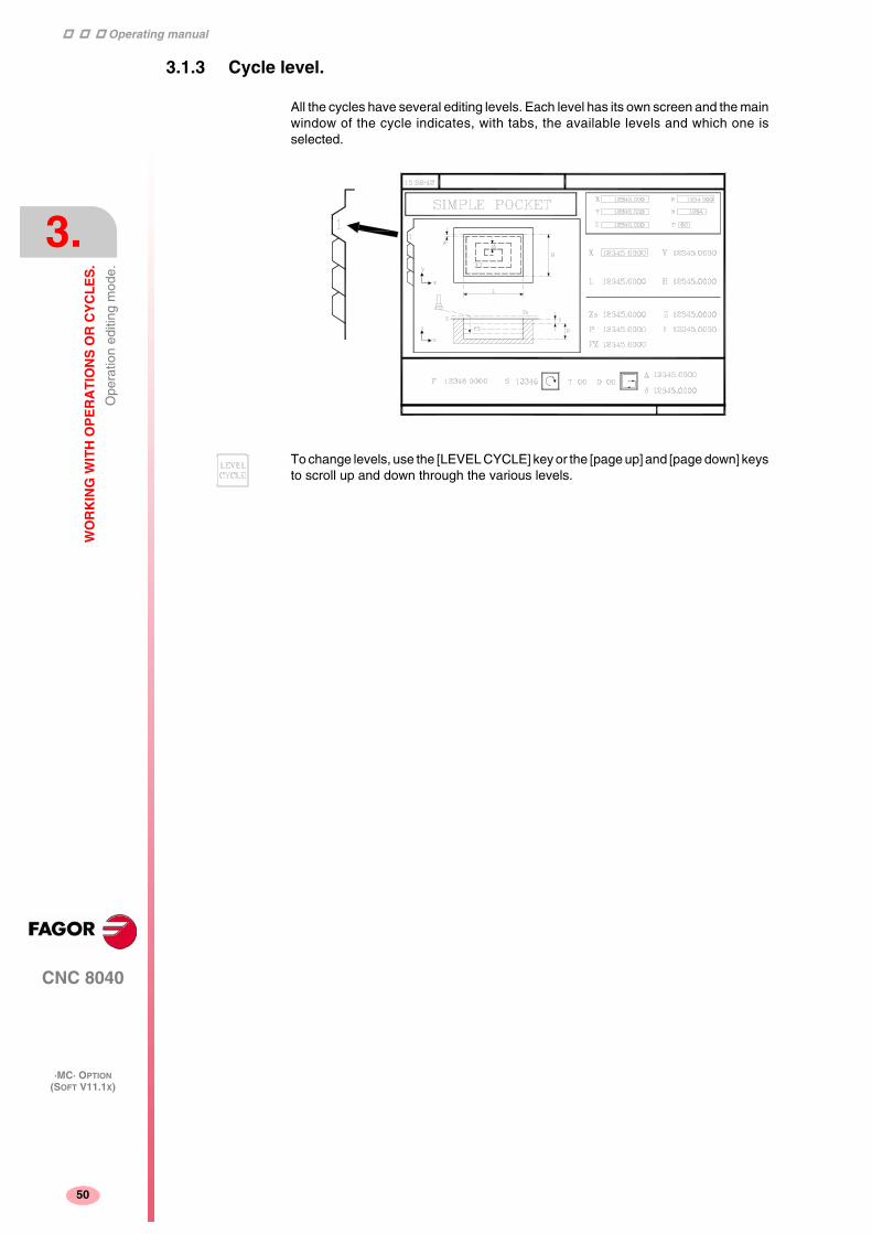
Operating manual
CNC 8040
3.
WO
RK
ING
WIT
H O
PE
RA
TIO
NS
OR
CY
CL
ES
.
Ope
ratio
n ed
iting
mod
e.
·MC· OPTION(SOFT V11.1X)
50
3.1.3 Cycle level.
All the cycles have several editing levels. Each level has its own screen and the mainwindow of the cycle indicates, with tabs, the available levels and which one isselected.
To change levels, use the [LEVEL CYCLE] key or the [page up] and [page down] keysto scroll up and down through the various levels.
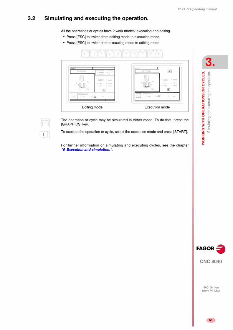
Operating manual
CNC 8040
WO
RK
ING
WIT
H O
PE
RA
TIO
NS
OR
CY
CL
ES
.
Sim
ulat
ing
and
exec
utin
g th
e op
erat
ion.
3.
·MC· OPTION(SOFT V11.1X)
51
3.2 Simulating and executing the operation.
All the operations or cycles have 2 work modes; execution and editing.
• Press [ESC] to switch from editing mode to execution mode.
• Press [ESC] to switch from executing mode to editing mode.
For further information on simulating and executing cycles, see the chapter"6 Execution and simulation.".
Editing mode Execution mode
The operation or cycle may be simulated in either mode. To do that, press the[GRAPHICS] key.
To execute the operation or cycle, select the execution mode and press [START].

Operating manual
CNC 8040
3.
WO
RK
ING
WIT
H O
PE
RA
TIO
NS
OR
CY
CL
ES
.
Sim
ulat
ing
and
exec
utin
g th
e op
erat
ion.
·MC· OPTION(SOFT V11.1X)
52
3.2.1 Background cycle editing.
It is possible to edit an operation or cycle while executing a program or part(background editing). The new operation edited may be saved as part of a part-program other than the one being executed.
The operation being edited in background cannot be executed or simulated, and thecurrent position of the machine cannot be assigned to a coordinate.
Use the following keys to inspect or change a tool while editing in background.
Pressing the [T] key without quitting background editing selects the T field of theoperation or of the canned cycle being edited.
Interrupts the execution and goes on editing in background.
To quit background editing.
To access tool inspection.
Background editing is not possible while executing an independent operationor cycle. It can only be done while executing a program or part.i

Operating manual
CNC 8040
WO
RK
ING
WIT
H O
PE
RA
TIO
NS
OR
CY
CL
ES
.
Pro
file
mill
ing
oper
atio
n.
3.
·MC· OPTION(SOFT V11.1X)
53
3.3 Profile milling operation.
Level 1.
The following data must be defined:
• The starting point (X1, Y1), the intermediate points (P1 through P12), the last point(Xn, Yn) and the machining conditions in Z (Zs, Z, P, I, Fz).
• Also, in the area for roughing operation data, it must be defined whether the millingoperation is carried out with or without tool compensation.
Level 2.
The following data must be defined:
• The starting point (X, Y), the "Profile program" number and the machiningconditions in Z (Zs, Z, P, I, Fz).
• Also, in the area for roughing operation data, it must be defined whether the millingoperation is carried out with or without tool compensation.
This key accesses the profile milling operation.
This cycle may be defined in two ways:

Operating manual
CNC 8040
3.
WO
RK
ING
WIT
H O
PE
RA
TIO
NS
OR
CY
CL
ES
.
Pro
file
mill
ing
oper
atio
n.
·MC· OPTION(SOFT V11.1X)
54
3.3.1 Data definition.
Coordinates of the first and last points.
The coordinates are defined one by one. After placing the cursor on the coordinateof the axes to be defined, the value is entered in one of the following ways.
• Entering the value manually. Key in the desired value and press [ENTER].
• Assign the current machine position.
Jog the axis with the handwheel or the JOG keys up to the desired point. Press[RECALL] so the selected data assumes the value shown in the top right windowand press [ENTER].
The top right window shows the tool position at all times.
Intermediate points (level 1).
The intermediate points are defined one by one. When not using the 12 definitionpoints, the first unused point must be defined with the same coordinates as the lastpoint of the profile.
The following must be defined for each point.
If a coordinate is left blank, the cycle will assume that it is the same as that of theprevious one.
The coordinates of each point may also be defined incrementally. To do that, selectthe desired coordinate with the cursor and press the two-color key. Bothcoordinates of the selected point will be shown preceded by the “∆” icon thatindicates the incremental value with respect to the previous point.
Machining conditions in Z (Zs, Z, P, I, Fz).
The machining conditions are defined one by one.
• The Zs and Z values are defined as the coordinates of the first and last points.
• To define the rest of the values (P, I, Fz), go to the corresponding window, keyin the desired value and press [ENTER].
If the penetration step is programmed with a positive sign (I+), the cyclerecalculates the step so all the penetrations are identical, this being equal to orless than the one programmed. If programmed with a negative sign (I-), the cycleis machined with the given pass (step) except the last pass that machines the rest.
• The X, Y coordinates are defined one by one like the coordinates of the first andlast points.
• Type of corner. To select the type of corner, place the cursor over this icon andpress the two-color key.
If defined... The CNC assumes...
X1 25.323 Y1 26.557 Point: X1 25.323 Y1 26.557
X2 Y2 78.998 Point: X2 25.323 Y2 78.998
X3 67.441 Y3 83.231 Point: X3 67.441 Y3 83.231
X4 Y4 Point: X4 67.441 Y4 83.231
X5 Y5 There are no more points, it is arepetition of the previous point.

Operating manual
CNC 8040
WO
RK
ING
WIT
H O
PE
RA
TIO
NS
OR
CY
CL
ES
.
Pro
file
mill
ing
oper
atio
n.
3.
·MC· OPTION(SOFT V11.1X)
55
Milling with or without tool radius compensation.
To select the type of corner, place the cursor over this icon and press the two-colorkey.
Without tool radius Compensation.
With lefthand tool radius compensation.
With righthand tool radius compensation.

Operating manual
CNC 8040
3.
WO
RK
ING
WIT
H O
PE
RA
TIO
NS
OR
CY
CL
ES
.
Pro
file
mill
ing
oper
atio
n.
·MC· OPTION(SOFT V11.1X)
56
3.3.2 Profile definition (level 2).
Defining the profile program.
The profile program may be defined as follows.
• Key in the profile program number directly.
If the "profile program" is known, key in the program number and press [ENTER].
• Access the "profile programs" to select one of them.
Press the [ ] key. The canned cycle will show a window with the profile programscurrently defined. Use the [ ] and [ ] keys to move around this window. Afterpositioning the cursor on the desired program, press [ENTER].
To exit this window without selecting any program, use the [ ] y [ ] keys.
Editing a new profile program.
To edit a new profile program, key in the program number (between 0 and 999) andpress [RECALL]. The CNC will show the window for the profile editor (see operationmanual).
Once the profile has been edited, the CNC requests the comment to be associatedwith the profile program being edited. Enter the desired comment and press [ENTER].If no comment is desired, press [ESC].
Copying a profile program.
Press the [ ] key. The canned cycle will show the profile programs currently defined.Place the cursor on the profile program to be copied and press [P.PROG]. The CNCrequests the number of the new profile and it allows changing its comment. If thenumber entered is the same as that of an existing profile, the CNC requestsconfirmation to replace it.
Modifying an existing profile program.
To modify a profile program, key in the program number and press [RECALL]. TheCNC will show, in the window for the profile editor, the profile that is currently defined.
With this profile, the following actions are possible:
• Adding new elements at the end of the current profile.
• Modifying the data of any element.
• Modifying or including chamfers, rounding, etc.
• Deleting elements of the profile.
Deleting an existing profile program.
Press the [ ] key. The canned cycle will show the profile programs currently defined.Place the cursor on the profile program to be deleted and press [CLEAR]. The CNCrequests confirmation.
The profile programs can also be accessed in the "M" mode because the CNCsaves them internally as P997xxx.
Example: Profile program 123 is internally saved as P997123.
When saving a part-program that contains a level-2 profile cycle into anexternal device, PC, floppy drive, etc. also save its associated profile programP997xxx.
i

Operating manual
CNC 8040
WO
RK
ING
WIT
H O
PE
RA
TIO
NS
OR
CY
CL
ES
.
Sur
face
mill
ing
and
slot
mill
ing
oper
atio
ns.
3.
·MC· OPTION(SOFT V11.1X)
57
3.4 Surface milling and slot milling operations.
Surface milling operation.
The following data must be defined:
• The type of surface milling, the starting point (X1, Y1), the dimensions of thesurface milling (L, H, E, α) and the machining conditions in Z (Zs, Z, P, I, Fz).
• Also, you must define the milling pass (∆) in the data area for the roughingoperation and the finishing stock (δz) in the data area for the finishing operation.
Slot milling operation.
The following data must be defined:
• The type of slot milling, the starting point (X1, Y1), the dimensions of the slot (L,H, E, α) and the machining conditions in Z (Zs, Z, P, I, Fz).
This key accesses the surface milling and slot milling operations.
• In the roughing area, define the milling pass (∆) and the machining direction.
• In the finishing area, define the finishing stocks (δ and δz), the number of finishingpasses and the machining direction.

Operating manual
CNC 8040
3.
WO
RK
ING
WIT
H O
PE
RA
TIO
NS
OR
CY
CL
ES
.
Sur
face
mill
ing
and
slot
mill
ing
oper
atio
ns.
·MC· OPTION(SOFT V11.1X)
58
3.4.1 Defining the surface milling data.
Type of surface milling.
Coordinates of starting point (X1, Y1).
Define one of the corners of the surface to be milled (X1, Y1). The coordinates aredefined one by one. After placing the cursor on the coordinate of the axes to bedefined, the value is entered in one of the following ways.
• Entering the value manually. Key in the desired value and press [ENTER].
• Assign the current machine position.
Jog the axis with the handwheel or the JOG keys up to the desired point. Press[RECALL] so the selected data assumes the value shown in the top right windowand press [ENTER].
The top right window shows the tool position at all times.
Surface to be milled (L, H, E, α).
After defining one of the corners (X1, Y1), define the length (L) and width (H) of thesurface to be milled. The sign of the L and H indicates the orientation referred to theX1, Y1 point.
• Once the surface to be milled has been defined, the icon shown at the bottom right(roughing and finishing area) may be used to select the corner to start milling thesurface.
• The data E and α are defined one by one. Place the cursor in the correspondingwindow, key in the desired value and press [ENTER].
When programming parameter "E" with a value smaller than the tool radius, theCNC executes the surface milling with an "E" value equal to the tool radius.
Machining conditions in Z (Zs, Z, P, I, Fz).
The machining conditions are defined one by one.
• The Zs and Z values are defined as the coordinates of the first and last points.
• To define the rest of the values (P, I, Fz), go to the corresponding window, keyin the desired value and press [ENTER].
If the penetration step is programmed with a positive sign (I+), the cyclerecalculates the step so all the penetrations are identical, this being equal to orless than the one programmed. If programmed with a negative sign (I-), the cycleis machined with the given pass (step) except the last pass that machines the rest.
Type of surface milling.
To select the type of surface milling, place the cursor over this icon and press the two-color key.
Operating manual
CNC 8040
WO
RK
ING
WIT
H O
PE
RA
TIO
NS
OR
CY
CL
ES
.
Sur
face
mill
ing
and
slot
mill
ing
oper
atio
ns.
3.
·MC· OPTION(SOFT V11.1X)
59
Milling pass (∆) and finishing stock (δz).
These data are defined one by one. Place the cursor in the corresponding window,key in the desired value and press [ENTER].

Operating manual
CNC 8040
3.
WO
RK
ING
WIT
H O
PE
RA
TIO
NS
OR
CY
CL
ES
.
Sur
face
mill
ing
and
slot
mill
ing
oper
atio
ns.
·MC· OPTION(SOFT V11.1X)
60
3.4.2 Defining the slot milling data.
Type of slot milling.
Coordinates of the starting point.
The coordinates are defined one by one. After placing the cursor on the coordinateof the axes to be defined, the value is entered in one of the following ways.
• Entering the value manually. Key in the desired value and press [ENTER].
• Assign the current machine position.
Jog the axis with the handwheel or the JOG keys up to the desired point. Press[RECALL] so the selected data assumes the value shown in the top right windowand press [ENTER].
The top right window shows the tool position at all times.
Dimensions of the slot (L, H, E, α).
These data are defined one by one. Place the cursor in the corresponding window,key in the desired value and press [ENTER].
When programming parameter "E" with a value smaller than the tool radius, the CNCexecutes the slot milling with an "E" value equal to the tool radius.
Machining conditions in Z (Zs, Z, P, I, Fz).
The machining conditions are defined one by one.
• The Zs and Z values are defined as the coordinates of the first and last points.
• To define the rest of the values (P, I, Fz), go to the corresponding window, keyin the desired value and press [ENTER].
If the penetration step is programmed with a positive sign (I+), the cyclerecalculates the step so all the penetrations are identical, this being equal to orless than the one programmed. If programmed with a negative sign (I-), the cycleis machined with the given pass (step) except the last pass that machines the rest.
Milling pass (∆) and finishing stock (δz).
These data are defined one by one. Place the cursor in the corresponding window,key in the desired value and press [ENTER].
Type of slot milling.
To select the type of slot milling, place the cursor over this icon and press the two-color key.

Operating manual
CNC 8040
WO
RK
ING
WIT
H O
PE
RA
TIO
NS
OR
CY
CL
ES
.
Sur
face
mill
ing
and
slot
mill
ing
oper
atio
ns.
3.
·MC· OPTION(SOFT V11.1X)
61
Clockwise milling of the different types of slots .

Operating manual
CNC 8040
3.
WO
RK
ING
WIT
H O
PE
RA
TIO
NS
OR
CY
CL
ES
.
Poc
ket c
ycle
with
a p
rofil
e
·MC· OPTION(SOFT V11.1X)
62
3.5 Pocket cycle with a profile
A pocket is composed by an external contour or profile (1) and a series of internalcontours or profiles (2). These internal profiles are called islands.
• In 2D pockets (top left figure), all the walls of the outside profile and of the islandsare vertical.
• In 3D pockets (top right figure), one, several or all the walls of the outside pocketand/or of the islands are not vertical (up to a maximum of 4).
Programming 2D pockets with profile.
When defining the profile, one must indicate, besides the outside contour of thepocket, the contour or contours of the islands.
The machining in Z is defined with the following parameters:
Zs Safety plane coordinate.
Z Part surface coordinate.
P Pocket depth.
I Step in Z.
Fz Penetrating feedrate in Z.
The following must be defined in the data area for the roughing operation:
β Sideways penetration angle.
∆ The milling pass.
The following must be defined in the data area for the finishing operation:
θ Sideways penetration angle.
δ Finishing stock on the side walls.
δz Finishing stock at the bottom.
N Number of finishing passes in Z.
This key accesses the pocket-with-profile operation.
There are two types of pocket with profile; 2D and 3D.
Pocket with 2D profile Pocket with 2D profile

Operating manual
CNC 8040
WO
RK
ING
WIT
H O
PE
RA
TIO
NS
OR
CY
CL
ES
.
Poc
ket c
ycle
with
a p
rofil
e
3.
·MC· OPTION(SOFT V11.1X)
63
Programming 3D pockets with profile.
Pocket identification number (POCK. 3D).
Several 3D pockets are possible. The CNC associates to each 3D pocket all itsdata (surface profile, depth profile, machining conditions, etc.).
Surface profile or profile in the XY plane. Profile (P. XY).
One must indicate, besides the outside contour of the pocket, the contour orcontours of the possible islands.
Depth profile for the first profile defined. Profile (P. Z1).
They usually correspond to the outside contour of the pocket.
Depth profile for the second profile defined. Profile (P. Z2).
They usually correspond to the contour of the first island defined.
Depth profile for the third profile defined. Profile (P. Z3).
They usually correspond to the contour of the second island defined.
Depth profile for the fourth profile defined. Profile (P. Z4).
They usually correspond to the contour of the third island defined.
The machining in Z is defined with the following parameters:
Zs Safety plane coordinate.
Z Part surface coordinate.
P Pocket depth.
I1 Roughing step in Z.
Fz Penetrating feedrate in Z.
I2 Semi-finishing step in Z.
The following must be defined in the data area for the roughing operation:
β Sideways penetration angle.
∆ The milling pass.
The following must be defined in the data area for the finishing operation:
R Tool tip radius.
δ Finishing stock on the side walls.
ε Finishing pass.
Once all the profiles have been defined, the configuration of the 3D pocket must bevalidated. To do that, place the cursor on the icon (a) and press [ENTER] to validatethe pocket. The cycle will show the icon (b).(a) (b)
Direction of the finishing passes on the walls.
The pocket configuration program and the profile programs can also beaccessed in the "M" mode because the CNC saves them internally as:
P995xxx - 3D pocket configuration.
P998xxx - The profiles of the XY plane, both in 2D and 3D pockets.
P996xxx - The depth profiles of the 3D pockets.
i

Operating manual
CNC 8040
3.
WO
RK
ING
WIT
H O
PE
RA
TIO
NS
OR
CY
CL
ES
.
Poc
ket c
ycle
with
a p
rofil
e
·MC· OPTION(SOFT V11.1X)
64
3.5.1 Data definition.
Machining conditions in Z (Zs, Z).
To define the values (Zs and Z), after going to the corresponding window, the valueis entered in one of the following ways.
• Entering the value manually. Key in the desired value and press [ENTER].
• Assign the current machine position.
Jog the axis with the handwheel or the JOG keys up to the desired point. Press[RECALL] so the selected data assumes the value shown in the top right windowand press [ENTER].
The top right window shows the tool position at all times.
Machining conditions in Z (P, Fz, I, I1, I2).
The machining conditions are defined one by one.
• To define the values (P, Fz, I, I1, I2), go to the corresponding window, key in thedesired value and press [ENTER].
If the penetration step is programmed with a positive sign (I+), the cyclerecalculates the step so all the penetrations are identical, this being equal to orless than the one programmed. If programmed with a negative sign (I-), the cycleis machined with the given pass (step) except the last pass that machines the rest.
Milling pass (∆) and finishing pass (ε).
Place the cursor in the corresponding window, roughing or finishing operation, keyin the desired value and press [ENTER].
Sideways penetration angles (β, θ).
Place the cursor in the corresponding window, roughing or finishing operation, keyin the desired value and press [ENTER].
Finishing stocks: on the side walls (δ) and at the bottom (δz).
Place the cursor in the corresponding window, finishing operation, key in the desiredvalue and press [ENTER].
Finishing tool tip radius (R).
Place the cursor in the corresponding window, finishing operation, key in the desiredvalue and press [ENTER].
Direction of the finishing passes on the walls.
To select the direction of the finishing passes on the walls, place the cursor over thisicon and press the two-color key.
Operating manual
CNC 8040
WO
RK
ING
WIT
H O
PE
RA
TIO
NS
OR
CY
CL
ES
.
Poc
ket c
ycle
with
a p
rofil
e
3.
·MC· OPTION(SOFT V11.1X)
65
3.5.2 Profile definition.
Defining the profile program.
The profile program may be defined as follows.
• Key in the profile program number directly.
If the "profile program" is known, key in the program number and press [ENTER].
• Access the "profile programs" to select one of them.
Press the [ ] key. The canned cycle will show a window with the profile programscurrently defined. There are 3 different directories, one for the pocketconfiguration profiles, another one for the profiles in the XY plane and anotherone for the depth profiles Use the [ ] and [ ] keys to move around this window.After positioning the cursor on the desired program, press [ENTER].
To exit this window without selecting any program, use the [ ] y [ ] keys.
Editing a new profile program.
To edit a new profile program, key in the program number (between 0 and 999) andpress [RECALL]. The CNC will show the window for the profile editor (see operationmanual).
Once the profile has been edited, the CNC requests the comment to be associatedwith the profile program being edited. Enter the desired comment and press [ENTER].If no comment is desired, press [ESC].
Copying a profile program.
Press the [ ] key. The canned cycle will show the profile programs currently defined.Place the cursor on the profile program to be copied and press [P.PROG]. The CNCrequests the number of the new profile and it allows changing its comment. If thenumber entered is the same as that of an existing profile, the CNC requestsconfirmation to replace it.
Modifying an existing profile program.
To modify a profile program, key in the program number and press [RECALL]. TheCNC will show, in the window for the profile editor, the profile that is currently defined.
With this profile, the following actions are possible:
• Adding new elements at the end of the current profile.
• Modifying the data of any element.
• Modifying or including chamfers, rounding, etc.
• Deleting elements of the profile.
Deleting an existing profile program.
Press the [ ] key. The canned cycle will show the profile programs currently defined.Place the cursor on the profile program to be deleted and press [CLEAR]. The CNCrequests confirmation.
The profile programs can also be accessed in the "M" mode because the CNCsaves them internally as:
P995xxx - 3D pocket configuration.
P998xxx - The profiles of the XY plane, both in 2D and 3D pockets.
P996xxx - The depth profiles of the 3D pockets.
When saving a part-program that contains a pocket-with-profile cycle into anexternal device, PC, floppy drive, etc. also save its associated profileprograms.
i

Operating manual
CNC 8040
3.
WO
RK
ING
WIT
H O
PE
RA
TIO
NS
OR
CY
CL
ES
.
Poc
ket c
ycle
with
a p
rofil
e
·MC· OPTION(SOFT V11.1X)
66
3.5.3 Profile definition examples.
Example of how to define a 2D profile without islands:
2D pocket.
Configuration.
Profile.
Corners.
End.
Save profile.
Profile 1 [RECALL]
Abscissa axis: X Ordinate axis: Y
Autozoom: Yes Validate
Starting point X 20 Y -8 Validate
Straight X 20 Y -40 Validate
Straight X 145 Y -40 Validate
Straight X 145 Y -25 Validate
Clockwise arc Xf 145 Yf 25 R 25 Validate
Straight X 145 Y 40 Validate
Straight X 20 Y 40 Validate
Straight X 20 Y 8 Validate
Straight X 55 Y 8 Validate
Straight X 55 Y -8 Validate
Straight X 20 Y -8 Validate
Lower left corner [ENTER] Chamfer 15 [ENTER]
Upper left corner [ENTER] Chamfer 15 [ENTER]
[ESC]

Operating manual
CNC 8040
WO
RK
ING
WIT
H O
PE
RA
TIO
NS
OR
CY
CL
ES
.
Poc
ket c
ycle
with
a p
rofil
e
3.
·MC· OPTION(SOFT V11.1X)
67
Example of how to define a 2D profile with islands:
2D pocket.
Configuration.
Profile (outside profile).
Corners.
New profile (island).
End.
Save profile.
Profile 2 [RECALL]
Abscissa axis: X Ordinate axis: Y
Autozoom: Yes Validate
Starting point X 20 Y 0 Validate
Straight X 20 Y -40 Validate
Straight X 145 Y -40 Validate
Straight X 145 Y 40 Validate
Straight X 20 Y 40 Validate
Straight X 20 Y 0 Validate
Lower left corner [ENTER] Chamfer 15 [ENTER]
Lower right corner [ENTER] Chamfer 15 [ENTER]
Upper right corner [ENTER] Chamfer 15 [ENTER]
Upper left corner [ENTER] Chamfer 15 [ENTER]
[ESC]
Profile
Starting point X 115 Y -25 Validate
Straight X 115 Y 0 Validate
Clockwise arc Xf 90 Yf 25 Xc 115 Yc 25 R 25 Validate
Straight X 50 Y 25 Validate
Straight X 50 Y 0 Validate
Clockwise arc Xf 75 Yf -25 Xc 50 Yc -25 R 25 Validate
Straight X 115 Y -25 Validate
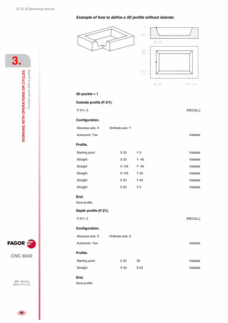
Operating manual
CNC 8040
3.
WO
RK
ING
WIT
H O
PE
RA
TIO
NS
OR
CY
CL
ES
.
Poc
ket c
ycle
with
a p
rofil
e
·MC· OPTION(SOFT V11.1X)
68
Example of how to define a 3D profile without islands:
3D pocket = 1
Outside profile (P.XY).
Configuration.
Profile.
End.
Save profile.
Depth profile (P.Z1).
Configuration.
Profile.
End.
Save profile.
P.XY= 3 [RECALL]
Abscissa axis: X Ordinate axis: Y
Autozoom: Yes Validate
Starting point X 20 Y 0 Validate
Straight X 20 Y -40 Validate
Straight X 145 Y -40 Validate
Straight X 145 Y 40 Validate
Straight X 20 Y 40 Validate
Straight X 20 Y 0 Validate
P.XY= 3 [RECALL]
Abscissa axis: X Ordinate axis: Z
Autozoom: Yes Validate
Starting point X 20 Z0 Validate
Straight X 30 Z-20 Validate

Operating manual
CNC 8040
WO
RK
ING
WIT
H O
PE
RA
TIO
NS
OR
CY
CL
ES
.
Poc
ket c
ycle
with
a p
rofil
e
3.
·MC· OPTION(SOFT V11.1X)
69
Example of how to define a 3D profile with islands:
3D pocket = 2
Outside profile (P.XY).
Configuration.
Profile (pocket profile).
Profile (island profile).
End.
Save profile.
Depth profile (P.Z1).
Configuration.
Profile (pocket depth profile).
P.XY= 4 [RECALL]
Abscissa axis: X Ordinate axis: Y
Autozoom: Yes Validate
Starting point X 20 Y 0 Validate
Straight X 20 Y -40 Validate
Straight X 145 Y -40 Validate
Straight X 145 Y 40 Validate
Straight X 20 Y 40 Validate
Straight X 20 Y 0 Validate
Circle X 62.5 Y0 Xc 82.5 Yc 0 Validate
P.Z1= 2 [RECALL]
Abscissa axis: X Ordinate axis: Z
Autozoom: Yes Validate
Starting point X 20 Z0 Validate
Straight X 30 Z-20 Validate
Operating manual
CNC 8040
3.
WO
RK
ING
WIT
H O
PE
RA
TIO
NS
OR
CY
CL
ES
.
Poc
ket c
ycle
with
a p
rofil
e
·MC· OPTION(SOFT V11.1X)
70
End.
Save profile.
Depth profile (P.Z2).
Configuration.
Profile (island depth profile).
End.
Save profile.
P.Z1= 3 [RECALL]
Abscissa axis: X Ordinate axis: Z
Autozoom: Yes Validate
Starting point X 77.5 Z0 Validate
Straight X 62.5 Z-20 Validate

Operating manual
CNC 8040
WO
RK
ING
WIT
H O
PE
RA
TIO
NS
OR
CY
CL
ES
.
Rec
tang
ular
and
circ
ular
bos
s cy
cles
.
3.
·MC· OPTION(SOFT V11.1X)
71
3.6 Rectangular and circular boss cycles.
Rectangular boss cycle.
The following data must be defined:
• The starting point (X1, Y1), the dimensions of the boss (L, H), the inclination angle(α), the amount of stock to be removed (Q), the type of corner and the machiningconditions in Z (Zs, Z, P, I, Fz).
Circular boss cycle.
The following data must be defined:
• The center coordinates, (Xc, Yc), the radius of the boss (R), the amount of stockto be removed (Q) and the machining conditions in Z (Zs, Z, P, I, Fz).
This key accesses the circular boss and rectangular boss operations.
• In the roughing area, define the milling pass (∆) and the machining direction.
• In the finishing area, define the finishing stocks (δ and δz), the number of finishingpasses and the machining direction.
• In the roughing area, define the milling pass (∆) and the machining direction.
• In the finishing area, define the finishing stocks (δ and δz), the number of finishingpasses and the machining direction.
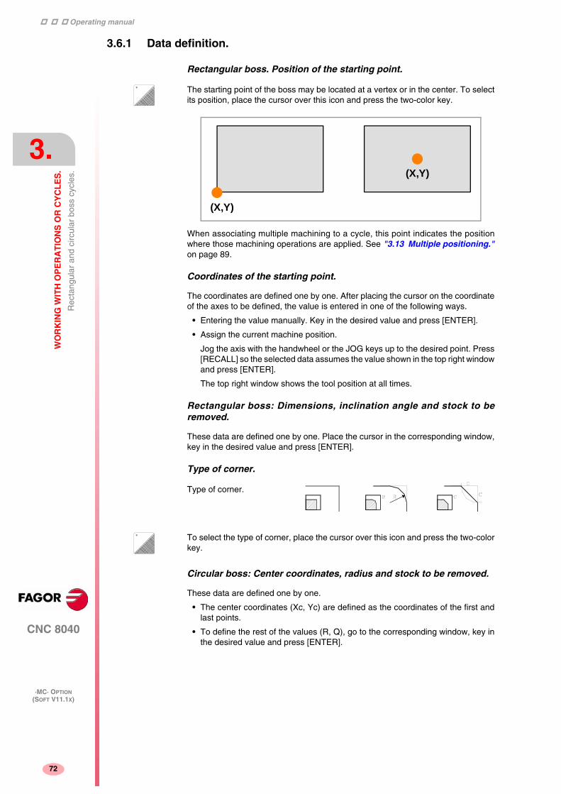
Operating manual
CNC 8040
3.
WO
RK
ING
WIT
H O
PE
RA
TIO
NS
OR
CY
CL
ES
.
Rec
tang
ular
and
circ
ular
bos
s cy
cles
.
·MC· OPTION(SOFT V11.1X)
72
3.6.1 Data definition.
Rectangular boss. Position of the starting point.
When associating multiple machining to a cycle, this point indicates the positionwhere those machining operations are applied. See "3.13 Multiple positioning."on page 89.
Coordinates of the starting point.
The coordinates are defined one by one. After placing the cursor on the coordinateof the axes to be defined, the value is entered in one of the following ways.
• Entering the value manually. Key in the desired value and press [ENTER].
• Assign the current machine position.
Jog the axis with the handwheel or the JOG keys up to the desired point. Press[RECALL] so the selected data assumes the value shown in the top right windowand press [ENTER].
The top right window shows the tool position at all times.
Rectangular boss: Dimensions, inclination angle and stock to beremoved.
These data are defined one by one. Place the cursor in the corresponding window,key in the desired value and press [ENTER].
Type of corner.
Circular boss: Center coordinates, radius and stock to be removed.
These data are defined one by one.
• The center coordinates (Xc, Yc) are defined as the coordinates of the first andlast points.
• To define the rest of the values (R, Q), go to the corresponding window, key inthe desired value and press [ENTER].
The starting point of the boss may be located at a vertex or in the center. To selectits position, place the cursor over this icon and press the two-color key.
Type of corner.
(X,Y)
(X,Y)
To select the type of corner, place the cursor over this icon and press the two-colorkey.

Operating manual
CNC 8040
WO
RK
ING
WIT
H O
PE
RA
TIO
NS
OR
CY
CL
ES
.
Rec
tang
ular
and
circ
ular
bos
s cy
cles
.
3.
·MC· OPTION(SOFT V11.1X)
73
Machining conditions in Z (Zs, Z, P, I, Fz).
The machining conditions are defined one by one.
• The Zs and Z values are defined as the coordinates of the first and last points.
• To define the rest of the values (P, I, Fz), go to the corresponding window, keyin the desired value and press [ENTER].
If the penetration step is programmed with a positive sign (I+), the cyclerecalculates the step so all the penetrations are identical, this being equal to orless than the one programmed. If programmed with a negative sign (I-), the cycleis machined with the given pass (step) except the last pass that machines the rest.
Milling pass (∆). Finishing stock on the side walls (δ) and at the bottom(δz). Number of finishing passes (N).
Place the cursor in the window for the finishing operation, key in the desired valueand press [ENTER].

Operating manual
CNC 8040
3.
WO
RK
ING
WIT
H O
PE
RA
TIO
NS
OR
CY
CL
ES
.
Rec
tang
ular
and
circ
ular
poc
ket c
ycle
s.
·MC· OPTION(SOFT V11.1X)
74
3.7 Rectangular and circular pocket cycles.
Rectangular pocket cycle (level 1).
The following data must be defined:
• The starting point (X, Y), the pocket dimensions (L, H) and the machiningconditions in Z (Zs, Z, P, I, Fz).
Rectangular pocket cycle (level 2).
The following data must be defined:
• The starting point (X, Y), the pocket dimensions (L, H), the inclination angle (α),the type of corner and the machining conditions in Z (Zs, Z, P, I, Fz).
This key accesses the circular pocket and rectangular pocket operations.
• Also, one must define the milling pass (∆), the finishing stock (δ) and themachining direction.
• In the roughing area, one must define the sideways penetration angle (β), themilling pass (∆) and the machining direction.
• In the finishing area, one must define the sideways penetration angle (θ), thefinishing stocks (δ and δz), the number of finishing passes (N) and the machiningdirection.

Operating manual
CNC 8040
WO
RK
ING
WIT
H O
PE
RA
TIO
NS
OR
CY
CL
ES
.
Rec
tang
ular
and
circ
ular
poc
ket c
ycle
s.
3.
·MC· OPTION(SOFT V11.1X)
75
Circular pocket cycle (level 1).
The following data must be defined:
• The center coordinates (Xc, Yc), the pocket radius (R) and the machiningconditions in Z (Zs, Z, P, I, Fz).
Circular pocket cycle (level 2).
This level is the right one to machine pre-emptied pockets or crowns.
The following data must be defined:
• The center coordinates (Xc, Yc), the inside radius (Ri) and the outside radius (Re)of the pocket and the machining conditions in Z (Zs, Z, P, I, Fz).
• In the roughing area, one must define the sideways penetration angle (β), themilling pass (∆) and the machining direction.
• In the finishing area, one must define the sideways penetration angle (θ), thefinishing stocks (δ and δz), the number of finishing passes (N) and the machiningdirection.
• In the roughing area, one must define the sideways penetration angle (β), themilling pass (∆) and the machining direction.
• In the finishing area, one must define the sideways penetration angle (θ), thefinishing stocks (δ and δz), the number of finishing passes (N) and the machiningdirection.

Operating manual
CNC 8040
3.
WO
RK
ING
WIT
H O
PE
RA
TIO
NS
OR
CY
CL
ES
.
Rec
tang
ular
and
circ
ular
poc
ket c
ycle
s.
·MC· OPTION(SOFT V11.1X)
76
3.7.1 Data definition.
Rectangular pocket. Position of the starting point.
When associating multiple machining to a cycle, this point indicates the positionwhere those machining operations are applied. See "3.13 Multiple positioning."on page 89.
Coordinates of the starting point.
The coordinates are defined one by one. After placing the cursor on the coordinateof the axes to be defined, the value is entered in one of the following ways.
• Entering the value manually. Key in the desired value and press [ENTER].
• Assign the current machine position.
Jog the axis with the handwheel or the JOG keys up to the desired point. Press[RECALL] so the selected data assumes the value shown in the top right windowand press [ENTER].
The top right window shows the tool position at all times.
Rectangular pocket: Dimensions and inclination angle.
These data are defined one by one. Place the cursor in the corresponding window,key in the desired value and press [ENTER].
Type of corner.
Circular pocket: Center coordinate and radii.
These data are defined one by one.
• The center coordinates (Xc, Yc) are defined as the coordinates of the first andlast points.
• To define the radii (R, Ri, Re), go to the corresponding window, key in the desiredvalue and press [ENTER].
Machining conditions in Z (Zs, Z, P, I, Fz).
The machining conditions are defined one by one.
• The Zs and Z values are defined as the coordinates of the first and last points.
• To define the rest of the values (P, I, Fz), go to the corresponding window, keyin the desired value and press [ENTER].
The starting point of the pocket may be located at a vertex or in the center. To selectits position, place the cursor over this icon and press the two-color key.
Type of corner.
(X,Y)
(X,Y)
To select the type of corner, place the cursor over this icon and press the two-colorkey.
If the pocket dimensions do not allow the specified corner rounding or chamfer, theCNC will do the chamfer or the rounding with the maximum value possible.

Operating manual
CNC 8040
WO
RK
ING
WIT
H O
PE
RA
TIO
NS
OR
CY
CL
ES
.
Rec
tang
ular
and
circ
ular
poc
ket c
ycle
s.
3.
·MC· OPTION(SOFT V11.1X)
77
If the penetration step is programmed with a positive sign (I+), the cyclerecalculates the step so all the penetrations are identical, this being equal to orless than the one programmed. If programmed with a negative sign (I-), the cycleis machined with the given pass (step) except the last pass that machines the rest.
Milling pass (∆). Finishing stock on the side walls (δ) and at the bottom(δz). Number of finishing passes (N).
Place the cursor in the window for the finishing operation, key in the desired valueand press [ENTER].
Sideways penetration angles (β, θ).
In the rectangular pocket, the penetration is carried out from the pocket centerfollowing the first machining path. The path is followed as many times as needed soit ends back in the center of the pocket.
In the circular pocket, the penetration is carried out from the pocket center followinga helical path with a radius equal to that of the tool and keeping the machiningdirection. The penetration (in feed) always ends in the center of the pocket.
Place the cursor in the corresponding window, roughing or finishing operation, keyin the desired value and press [ENTER].

Operating manual
CNC 8040
3.
WO
RK
ING
WIT
H O
PE
RA
TIO
NS
OR
CY
CL
ES
.
Pos
ition
ing
(2 le
vels
)
·MC· OPTION(SOFT V11.1X)
78
3.8 Positioning (2 levels)
Level 1.
The following data must be defined:
• The target point ((X, Y, Z)), the axis moving order and the type of feedrate.
Level 2.
The following data must be defined:
• The target point ((X, Y, Z)), the axis moving order, the type of feedrate and theauxiliary "M" functions that will be executed before and after the movement.
This key accesses the positioning operations.

Operating manual
CNC 8040
WO
RK
ING
WIT
H O
PE
RA
TIO
NS
OR
CY
CL
ES
.
Pos
ition
ing
(2 le
vels
)
3.
·MC· OPTION(SOFT V11.1X)
79
3.8.1 Data definition.
Coordinates of the starting point.
The coordinates are defined one by one. After placing the cursor on the coordinateof the axes to be defined, the value is entered in one of the following ways.
• Entering the value manually. Key in the desired value and press [ENTER].
• Assign the current machine position.
Jog the axis with the handwheel or the JOG keys up to the desired point. Press[RECALL] so the selected data assumes the value shown in the top right windowand press [ENTER].
The top right window shows the tool position at all times.
Order in which the axes move.
Type of feedrate.
Auxiliary (miscellaneous) "M" functions.
The functions will be executed in the same order they are inserted on the list.
Select the corresponding window with the [ ][ ] keys Use the [ ] and [ ] keys tomove around the window.
To delete a function, select it and press [CLEAR]
To select the moving order, place the cursor over this icon and press the two-colorkey.
All three axes at the same time.
First the Z axis and then the plane (X and Y axes at the same time).
First the plane (X and Y axes at the same time) and then the Z axis.
To select the type of feedrate, place the cursor over this icon and press the two-colorkey.
Programmed feedrate.
Rapid traverse.

Operating manual
CNC 8040
3.
WO
RK
ING
WIT
H O
PE
RA
TIO
NS
OR
CY
CL
ES
.
Bor
ing
oper
atio
n.
·MC· OPTION(SOFT V11.1X)
80
3.9 Boring operation.
Boring operation (level 1).
The following data must be defined:
• The machining point (X, Y), the coordinate of the safety plane (Zs), the coordinateof the part surface (Z), the total machining depth (P) and the dwell at the bottom (t).
Boring operation (level 2).
This level is only available when using spindle orientation. This level may be used,after the quail has penetrated, to orient the spindle, retract the quail before the exitmovement, thus preventing the part from scratching.
The following data must be defined:
• The machining point (X, Y), the coordinate of the safety plane (Zs), the coordinateof the part surface (Z), the total machining depth (P) and the dwell at the bottom(t) and the data for quail orientation and retraction (αs, ∆x, ∆y).
This key accesses the boring operations.

Operating manual
CNC 8040
WO
RK
ING
WIT
H O
PE
RA
TIO
NS
OR
CY
CL
ES
.
Bor
ing
oper
atio
n.
3.
·MC· OPTION(SOFT V11.1X)
81
3.9.1 Data definition.
Coordinates of the machining point.
The coordinates are defined one by one. After placing the cursor on the coordinateof the axes to be defined, the value is entered in one of the following ways.
• Entering the value manually. Key in the desired value and press [ENTER].
• Assign the current machine position.
Jog the axis with the handwheel or the JOG keys up to the desired point. Press[RECALL] so the selected data assumes the value shown in the top right windowand press [ENTER].
The top right window shows the tool position at all times.
Machining conditions in Z (Zs, Z, P, I, t).
The machining conditions are defined one by one.
• The Zs and Z values are defined as the coordinates of the machining point.
• To define the rest of the values (P, t), go to the corresponding window, key in thedesired value and press [ENTER].
Exit type at level 1.
The exit movement may be done in two ways:
Data for quail orientation and retraction (αs, Dx, Dy).
These data are defined one by one. Place the cursor in the corresponding window,key in the desired value and press [ENTER].
It first orients the quail, it then moves back in XY and finally goes up in rapid (G00)with the spindle stopped.
To select the type of exit, place the cursor over this icon and press the two-color key.
At machining feedrate (G01) and with the spindle turning.
In rapid (G00) and with the spindle stopped.

Operating manual
CNC 8040
3.
WO
RK
ING
WIT
H O
PE
RA
TIO
NS
OR
CY
CL
ES
.
Rea
min
g op
erat
ion.
·MC· OPTION(SOFT V11.1X)
82
3.10 Reaming operation.
Reaming operation.
The following data must be defined:
• The machining point (X, Y), the coordinate of the safety plane (Zs), the coordinateof the part surface (Z), the total machining depth (P) and the dwell at the bottom (t).
This key accesses the reaming operation.

Operating manual
CNC 8040
WO
RK
ING
WIT
H O
PE
RA
TIO
NS
OR
CY
CL
ES
.
Rea
min
g op
erat
ion.
3.
·MC· OPTION(SOFT V11.1X)
83
3.10.1 Data definition.
Coordinates of the machining point.
The coordinates are defined one by one. After placing the cursor on the coordinateof the axes to be defined, the value is entered in one of the following ways.
• Entering the value manually. Key in the desired value and press [ENTER].
• Assign the current machine position.
Jog the axis with the handwheel or the JOG keys up to the desired point. Press[RECALL] so the selected data assumes the value shown in the top right windowand press [ENTER].
The top right window shows the tool position at all times.
Machining conditions in Z (Zs, Z, P, I, t).
The machining conditions are defined one by one.
• The Zs and Z values are defined as the coordinates of the machining point.
• To define the rest of the values (P, t), go to the corresponding window, key in thedesired value and press [ENTER].

Operating manual
CNC 8040
3.
WO
RK
ING
WIT
H O
PE
RA
TIO
NS
OR
CY
CL
ES
.
Tap
ping
ope
ratio
n.
·MC· OPTION(SOFT V11.1X)
84
3.11 Tapping operation.
Tapping operation.
The following data must be defined:
• The machining point (X, Y), the coordinate of the safety plane (Zs), the coordinateof the part surface (Z), the total machining depth (P) and the dwell at the bottom(t) and the type of tapping.
This key accesses the tapping operation.

Operating manual
CNC 8040
WO
RK
ING
WIT
H O
PE
RA
TIO
NS
OR
CY
CL
ES
.
Tap
ping
ope
ratio
n.
3.
·MC· OPTION(SOFT V11.1X)
85
3.11.1 Data definition.
Coordinates of the machining point.
The coordinates are defined one by one. After placing the cursor on the coordinateof the axes to be defined, the value is entered in one of the following ways.
• Entering the value manually. Key in the desired value and press [ENTER].
• Assign the current machine position.
Jog the axis with the handwheel or the JOG keys up to the desired point. Press[RECALL] so the selected data assumes the value shown in the top right windowand press [ENTER].
The top right window shows the tool position at all times.
Machining conditions in Z (Zs, Z, P, I, t).
The machining conditions are defined one by one.
• The Zs and Z values are defined as the coordinates of the machining point.
• To define the rest of the values (P, t), go to the corresponding window, key in thedesired value and press [ENTER].
Type of tapping.
Thread definition.
The cycle offers two ways to define the thread:
• Defining the pitch (p) the spindle speed (S).
• Defining the feedrate (F) the spindle speed (S).
To select one of the ways, the "Penetration" area shows an icon with 2 states [p, S]and [F, S]. To select the desired one, select the icon and press the two-color key, thecycle will show the selected fields.
Rigid tapping. Without a clutch.
Non-rigid tapping. With a clutch.
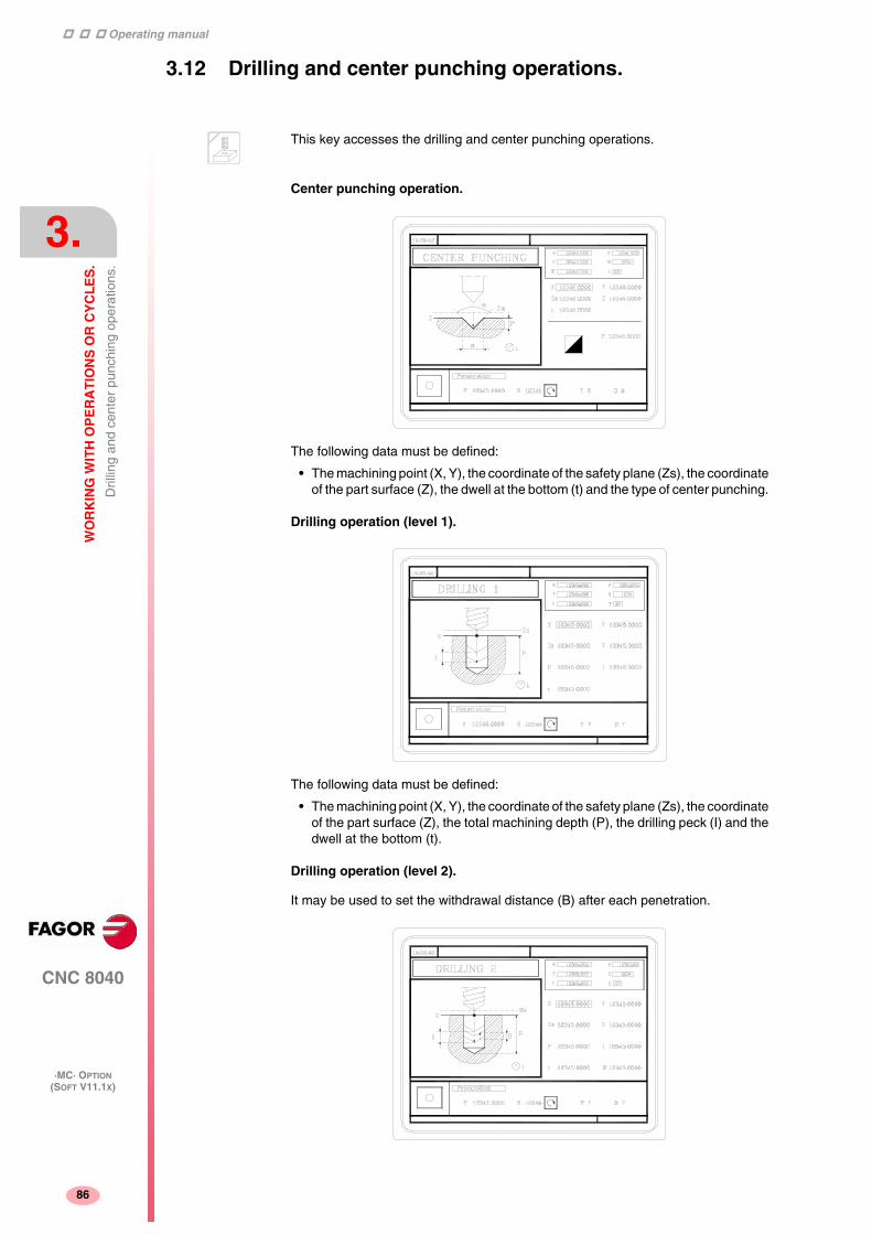
Operating manual
CNC 8040
3.
WO
RK
ING
WIT
H O
PE
RA
TIO
NS
OR
CY
CL
ES
.
Dril
ling
and
cent
er p
unch
ing
oper
atio
ns.
·MC· OPTION(SOFT V11.1X)
86
3.12 Drilling and center punching operations.
Center punching operation.
The following data must be defined:
• The machining point (X, Y), the coordinate of the safety plane (Zs), the coordinateof the part surface (Z), the dwell at the bottom (t) and the type of center punching.
Drilling operation (level 1).
The following data must be defined:
• The machining point (X, Y), the coordinate of the safety plane (Zs), the coordinateof the part surface (Z), the total machining depth (P), the drilling peck (I) and thedwell at the bottom (t).
Drilling operation (level 2).
It may be used to set the withdrawal distance (B) after each penetration.
This key accesses the drilling and center punching operations.

Operating manual
CNC 8040
WO
RK
ING
WIT
H O
PE
RA
TIO
NS
OR
CY
CL
ES
.
Dril
ling
and
cent
er p
unch
ing
oper
atio
ns.
3.
·MC· OPTION(SOFT V11.1X)
87
The following data must be defined:
• The machining point (X, Y), the coordinate of the safety plane (Zs), the coordinateof the part surface (Z), the total machining depth (P), the drilling peck (I) and thedwell at the bottom (t) and the withdrawal distance after each penetration (B).
Drilling operation (level 3).
It may be used to set the withdrawal coordinate (Zr) after each penetration.
The following data must be defined:
• The machining point (X, Y), the coordinate of the safety plane (Zs), the coordinateof the part surface (Z), the withdrawal coordinate (Zr), the total machining depth(P), the drilling peck (I) and the dwell at the bottom (t).

Operating manual
CNC 8040
3.
WO
RK
ING
WIT
H O
PE
RA
TIO
NS
OR
CY
CL
ES
.
Dril
ling
and
cent
er p
unch
ing
oper
atio
ns.
·MC· OPTION(SOFT V11.1X)
88
3.12.1 Data definition.
Coordinates of the machining point.
The coordinates are defined one by one. After placing the cursor on the coordinateof the axes to be defined, the value is entered in one of the following ways.
• Entering the value manually. Key in the desired value and press [ENTER].
• Assign the current machine position.
Jog the axis with the handwheel or the JOG keys up to the desired point. Press[RECALL] so the selected data assumes the value shown in the top right windowand press [ENTER].
The top right window shows the tool position at all times.
Machining conditions in Z (Zs, Z, Zr, P, I, t, B).
The machining conditions are defined one by one.
• The Zs and Z values are defined as the coordinates of the machining point.
• To define the rest of the values (Zr, P, I, t, B), go to the corresponding window,key in the desired value and press [ENTER].
Type of center punching.
• Defining the total machining depth (P).
• Defining the angle of the punch (α) and the diameter of the point (Φ).
To define the values (P, α, Φ), go to the corresponding window, key in the desiredvalue and press [ENTER].
To select the type of tapping, place the cursor over this icon and press the two-colorkey. The type of center punching may be defined in two ways.

Operating manual
CNC 8040
WO
RK
ING
WIT
H O
PE
RA
TIO
NS
OR
CY
CL
ES
.
Mul
tiple
pos
ition
ing.
3.
·MC· OPTION(SOFT V11.1X)
89
3.13 Multiple positioning.
Some cycles may be carried out in the tool position or may be associated a multiplepositioning so the cycle may be repeated in several locations. Multiple positioningmay be associated with the following cycles.
• Boring, reaming, tapping, drilling and center punching operations.
• 2D and 3D pockets.
• Bosses.
Use the following keys to select multiple positioning. The positioning moves may beselected with each one of the following keys:
When using one of these keys, the CNC selects the corresponding positioning andchanges the display on the screen. The CNC keeps the lamp for the selectedoperation (pocket, boss, boring, reaming, etc.) on and the bottom of the screen showsthe data for that operation.
Associating a multiple positioning with a cycle.
A multiple positioning may be associated with a cycle as follows:
1. Definition of the machining cycle, including the position of the starting point.
2. Selection of the type of positioning to be associated with.
3. Programming of the different points of the positioning.
The cycle assumes as first positioning point the starting point of the machiningoperation. This point may be modified when defining the positioning.
In 2D and 3D pockets, the reference points for the positioning must be the startingpoint of the outside profile.
To de-select a cycle and return to the standard screen, press the key for the selectedcycle (the one with the lamp on) or the [ESC] key.
Multiple positioning in pockets and bosses.
The screens of the pockets and bosses will indicate with icons which positioning theyhave associated or whether they are alone.
Multiple positioning in several locations.
Multiple positioning in a straight line.
Multiple positioning in an arc.
Multiple positioning in a rectangular pattern.
Multiple positioning in a grid pattern.

Operating manual
CNC 8040
3.
WO
RK
ING
WIT
H O
PE
RA
TIO
NS
OR
CY
CL
ES
.
Mul
tiple
pos
ition
ing.
·MC· OPTION(SOFT V11.1X)
90
In the positioning, an icon will show the pocket or boss to be repeated and the bottomscreen will give information on its geometry (except in profile pockets). The startingposition of rectangular pockets and bosses may be changed; the positioningmovements will be different depending on whether the starting point is at the vertexor in the center.
When machining pockets and bosses at the different positions, proceed as follows:
• There is neither roughing or finishing operation.
The machining takes place point to point; the whole cycle is executed at each point(there is no tool change).
• There is a roughing and finishing operation with the same tool and it is not possibleto program "M" functions between them.
The machining takes place point to point; the whole cycle is executed at each point(there is no tool change).
• There is a roughing and finishing operation with a different tool or it is possibleto program "M" functions between them.
It first does the roughing and then all the finishing operations (only one toolchange).
Rectangular pocket in different multiple positionings.
The availability of "M" functions in the cycles is determined with g.m.p."CODISET (P147)". i
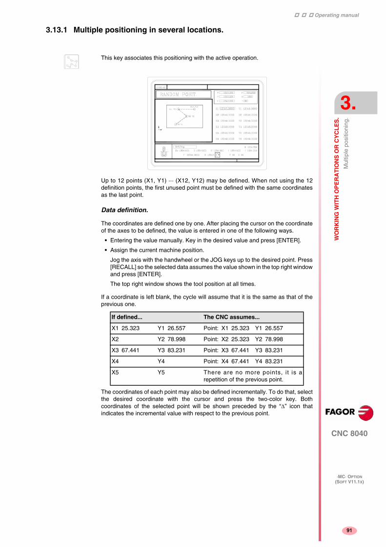
Operating manual
CNC 8040
WO
RK
ING
WIT
H O
PE
RA
TIO
NS
OR
CY
CL
ES
.
Mul
tiple
pos
ition
ing.
3.
·MC· OPTION(SOFT V11.1X)
91
3.13.1 Multiple positioning in several locations.
Up to 12 points (X1, Y1) ··· (X12, Y12) may be defined. When not using the 12definition points, the first unused point must be defined with the same coordinatesas the last point.
Data definition.
The coordinates are defined one by one. After placing the cursor on the coordinateof the axes to be defined, the value is entered in one of the following ways.
• Entering the value manually. Key in the desired value and press [ENTER].
• Assign the current machine position.
Jog the axis with the handwheel or the JOG keys up to the desired point. Press[RECALL] so the selected data assumes the value shown in the top right windowand press [ENTER].
The top right window shows the tool position at all times.
If a coordinate is left blank, the cycle will assume that it is the same as that of theprevious one.
The coordinates of each point may also be defined incrementally. To do that, selectthe desired coordinate with the cursor and press the two-color key. Bothcoordinates of the selected point will be shown preceded by the “∆” icon thatindicates the incremental value with respect to the previous point.
This key associates this positioning with the active operation.
If defined... The CNC assumes...
X1 25.323 Y1 26.557 Point: X1 25.323 Y1 26.557
X2 Y2 78.998 Point: X2 25.323 Y2 78.998
X3 67.441 Y3 83.231 Point: X3 67.441 Y3 83.231
X4 Y4 Point: X4 67.441 Y4 83.231
X5 Y5 There are no more points, i t is arepetition of the previous point.

Operating manual
CNC 8040
3.
WO
RK
ING
WIT
H O
PE
RA
TIO
NS
OR
CY
CL
ES
.
Mul
tiple
pos
ition
ing.
·MC· OPTION(SOFT V11.1X)
92
3.13.2 Multiple positioning in a straight line.
Data definition.
The coordinates are defined one by one. After placing the cursor on the coordinateof the axes to be defined, the value is entered in one of the following ways.
• Entering the value manually. Key in the desired value and press [ENTER].
• Assign the current machine position.
Jog the axis with the handwheel or the JOG keys up to the desired point. Press[RECALL] so the selected data assumes the value shown in the top right windowand press [ENTER].
The top right window shows the tool position at all times.
To define the rest of the values (I, N, α, L), go to the corresponding window, key inthe desired value and press [ENTER].
This key associates this positioning with the active operation.
The positioning may be defined in 5 ways. To select the desired type, place the cursorover the icon and press the two-color key. The icon shows the selected option andthe total number of options available.
1) Coordinates of the starting point. (X1, Y1)
Coordinates of the last point. (Xn, Yn)Distance between machining operations. (I)
2) Coordinates of the starting point. (X1, Y1)
Coordinates of the last point. (Xn, Yn)Number of points to machine. (N)
3) Coordinates of the starting point. (X1, Y1)
Inclination angle. (α)
Distance to travel. (L)Distance between machining operations. (I)
4) Coordinates of the starting point. (X1, Y1)
Inclination angle. (α)Distance to travel. (L)
Number of points to machine. (N)
5) Coordinates of the starting point. (X1, Y1)Inclination angle. (α)
Number of points to machine. (N)
Distance between machining operations. (I)

Operating manual
CNC 8040
WO
RK
ING
WIT
H O
PE
RA
TIO
NS
OR
CY
CL
ES
.
Mul
tiple
pos
ition
ing.
3.
·MC· OPTION(SOFT V11.1X)
93
3.13.3 Multiple positioning in an arc.
Multiple positioning in an arc (level 1).
This key associates this positioning with the active operation.
The positioning may be defined in 6 ways. To select the desired type, place the cursorover the icon and press the two-color key. The icon shows the selected option andthe total number of options available.
1) Coordinates of the starting point. (X1, Y1)
Center coordinates. (Xc, Yc)Angle of the last point. (τ)
Angular distance between machining operations. (β:
2) Coordinates of the starting point. (X1, Y1)
The radius. (R)Angle of the starting point. (α)
Angle of the last point. (τ)
Angular distance between machining operations. (β:
3) Coordinates of the starting point (X1, Y1)
Center coordinates (Xc, Yc)
Number of points to machine (N)Angle of the last point (τ)
4) Coordinates of the starting point (X1, Y1)
Center coordinates (Xc, Yc)Number of points to machine (N)
Angular distance between machining operations (β:
5) Coordinates of the starting point (X1, Y1)Radius (R)
Angle of the starting point (α)
Number of points to machine (N)Angle of the last point (τ)
6) Coordinates of the starting point (X1, Y1)
Radius (R)Angle of the starting point (α)
Number of points to machine (N)
Angular distance between machining operations (β:

Operating manual
CNC 8040
3.
WO
RK
ING
WIT
H O
PE
RA
TIO
NS
OR
CY
CL
ES
.
Mul
tiple
pos
ition
ing.
·MC· OPTION(SOFT V11.1X)
94
Multiple positioning in an arc (level 2).
The following data must be defined:
• Center coordinates (Xc, Yc).
• The starting point in Polar coordinates; Radius (R) and angle (α).
2 of the following data must be defined. When defining all 3 of them (if they are otherthan 0), the cycle assumes the (N) and (β) values.
(N) Number of points to machine.
(β) Angular distance between machining operations.
(τ) Angle of the last point.
Data definition.
The coordinates are defined one by one. After placing the cursor on the coordinateof the axes to be defined, the value is entered in one of the following ways.
• Entering the value manually. Key in the desired value and press [ENTER].
• Assign the current machine position.
Jog the axis with the handwheel or the JOG keys up to the desired point. Press[RECALL] so the selected data assumes the value shown in the top right windowand press [ENTER].
The top right window shows the tool position at all times.
To define the rest of the values (R, N, α, β, τ), go to the corresponding window, keyin the desired value and press [ENTER].

Operating manual
CNC 8040
WO
RK
ING
WIT
H O
PE
RA
TIO
NS
OR
CY
CL
ES
.
Mul
tiple
pos
ition
ing.
3.
·MC· OPTION(SOFT V11.1X)
95
3.13.4 Multiple positioning in a rectangular pattern.
Data definition.
The coordinates are defined one by one. After placing the cursor on the coordinateof the axes to be defined, the value is entered in one of the following ways.
• Entering the value manually. Key in the desired value and press [ENTER].
• Assign the current machine position.
Jog the axis with the handwheel or the JOG keys up to the desired point. Press[RECALL] so the selected data assumes the value shown in the top right windowand press [ENTER].
The top right window shows the tool position at all times.
To define the rest of the values (Lx, Ly, Ix, Iy, α, β, Nx, Ny), go to the correspondingwindow, key in the desired value and press [ENTER].
This key associates this positioning with the active operation.
The positioning may be defined in 3 ways. To select the desired type, place the cursorover the icon and press the two-color key. The icon shows the selected option andthe total number of options available.
1) Coordinates of the starting point (X1, Y1)
X and Y lengths (Lx, Ly)X and Y distances between machining operations. (Ix, Iy)
Rotation angle (α)
Angle between paths (β:
2) Coordinates of the starting point (X1, Y1)
X and Y lengths (Lx, Ly)
Number of machining operations on X and Y (Nx, Ny)
Rotation angle (α)Angle between paths (β:
3) Coordinates of the starting point (X1, Y1)
X and Y distances between machining operations. (Ix, Iy)Number of machining operations on X and Y (Nx, Ny)
Rotation angle (α)
Angle between paths (β:

Operating manual
CNC 8040
3.
WO
RK
ING
WIT
H O
PE
RA
TIO
NS
OR
CY
CL
ES
.
Mul
tiple
pos
ition
ing.
·MC· OPTION(SOFT V11.1X)
96
3.13.5 Multiple positioning in a grid pattern.
Data definition.
The coordinates are defined one by one. After placing the cursor on the coordinateof the axes to be defined, the value is entered in one of the following ways.
• Entering the value manually. Key in the desired value and press [ENTER].
• Assign the current machine position.
Jog the axis with the handwheel or the JOG keys up to the desired point. Press[RECALL] so the selected data assumes the value shown in the top right windowand press [ENTER].
The top right window shows the tool position at all times.
To define the rest of the values (Lx, Ly, Ix, Iy, α, β, Nx, Ny), go to the correspondingwindow, key in the desired value and press [ENTER].
This key associates this positioning with the active operation.
The positioning may be defined in 3 ways. To select the desired type, place the cursorover the icon and press the two-color key. The icon shows the selected option andthe total number of options available.
1) Coordinates of the starting point (X1, Y1)
X and Y lengths (Lx, Ly)X and Y distances between machining operations. (Ix, Iy)
Rotation angle (α)
Angle between paths (β:
2) Coordinates of the starting point (X1, Y1)
X and Y lengths (Lx, Ly)
Number of machining operations on X and Y (Nx, Ny)
Rotation angle (α)Angle between paths (β:
3) Coordinates of the starting point (X1, Y1)
X and Y distances between machining operations. (Ix, Iy)Number of machining operations on X and Y (Nx, Ny)
Rotation angle (α)
Angle between paths (β:
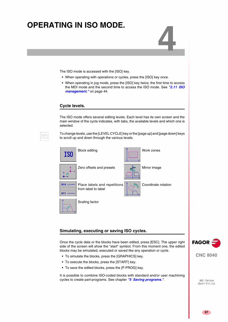
97
CNC 8040
·MC· OPTION(SOFT V11.1X)
4OPERATING IN ISO MODE.
The ISO mode is accessed with the [ISO] key.
• When operating with operations or cycles, press the [ISO] key once.
• When operating in jog mode, press the [ISO] key twice; the first time to accessthe MDI mode and the second time to access the ISO mode. See "2.11 ISOmanagement." on page 44.
Cycle levels.
The ISO mode offers several editing levels. Each level has its own screen and themain window of the cycle indicates, with tabs, the available levels and which one isselected.
Simulating, executing or saving ISO cycles.
Once the cycle data or the blocks have been edited, press [ESC]. The upper rightside of the screen will show the "start" symbol. From this moment one, the editedblocks may be simulated, executed or saved like any operation or cycle.
• To simulate the blocks, press the [GRAPHICS] key.
• To execute the blocks, press the [START] key.
• To save the edited blocks, press the [P.PROG] key.
It is possible to combine ISO-coded blocks with standard and/or user machiningcycles to create part-programs. See chapter "5 Saving programs.".
To change levels, use the [LEVEL CYCLE] key or the [page up] and [page down] keysto scroll up and down through the various levels.
Block editing Work zones
Zero offsets and presets Mirror image
Place labels and repetitionsfrom label to label
Coordinate rotation
Scaling factor

Operating manual
CNC 8040
4.
OP
ER
AT
ING
IN IS
O M
OD
E.
Edi
ting
bloc
ks in
ISO
mod
e.
·MC· OPTION(SOFT V11.1X)
98
4.1 Editing blocks in ISO mode.
When accessing the ISO mode, the CNC displays a special screen for editing up to6 program blocks either in ISO code or in high level language. After editing a block,press [ENTER] to validate it.
Once the block or blocks have been edited, press [ESC]. The upper right side of thescreen will show the "start" symbol. From this moment one, the edited blocks maybe simulated, executed or saved like any operation or cycle.
G95 G96 S120 M3
G0 Z100
G1 X30 F0.1
Example:

Operating manual
CNC 8040
OP
ER
AT
ING
IN IS
O M
OD
E.
Pro
gram
min
g as
sist
ance
.
4.
·MC· OPTION(SOFT V11.1X)
99
4.2 Programming assistance.
4.2.1 Zero offsets and presets.
4.2.2 Work zones.
4.2.3 Place labels and repetitions from label to label.
The icon may be used to select the following options:
• Machine zero. It cancels any zero offset and assumes themachine zero (home) as reference.
• Absolute zero offset. It permits defining, enabling or defining+ enabling the absolute zero offsets (G54 to G57).
• The zero offset is selected with an icon.
• Incremental offset: It permits defining, enabling or defining +enabling the incremental zero offsets (G58 or G59). The zerooffset to be activated is selected with an icon.
• Preset: The preset value for the active axes may be edited onthe screen. If any of them is not to be preset, leave its fieldempty.
The cycle internally generates a block with function G53,G54...G59 or G92.
Pressing the [ZERO] key accesses the zero offset table.
The icons may be used to defined the following options:
• Select the work zone to act upon. Up to five different zonesmay be defined.
• Type of action to carry out with the zone. A zone may bedefined, enabled, defined+enabled or disabled.
• Define the type of zone. Each one of them may be definedeither as a no-entry or no-exit zone.
The numeric fields permit editing the lower and upper limits of thezone. The limits are defined on the X, Y, Z axes. To only defineeither the upper or the lower limit, leave the values of the other limitblank.
The cycle internally generates up to three blocks with functionsG20, G21 and G22.
This cycle permits editing labels and repetition blocks betweentwo labels. It is selected with an icon.
• Edit labels. There is a field to enter the block number ananother one to add a comment.
The cycle generates this type of a block: N10; -> Comment.
• Block repetition. The repetition takes place between the firstand final labels programmed, the number of times that isindicated.
The cycle internally generates an RPT block.

Operating manual
CNC 8040
4.
OP
ER
AT
ING
IN IS
O M
OD
E.
Pro
gram
min
g as
sist
ance
.
·MC· OPTION(SOFT V11.1X)
100
4.2.4 Mirror image.
4.2.5 Scaling factor.
4.2.6 Coordinate rotation.
The icons may be used to select the following options:
• Select the action to be carried out. It is possible to cancel theactive mirror image, define a new one canceling the previousones or define a new one and add it to the one that is currentlyactive.
• Select the axes upon which mirror image is applied. For a newmirror image, it is possible to choose from the X, Y or X-Y axes.For an additive mirror image, it is possible to choose betweenthe X and Y axes. This icon is not displayed when selecting tocancel the mirror image.
The cycle internally generates an ISO block that contains acombination of functions G10, G11 and G12.
An icon is used to indicate whether to cancel the existing scalingfactor or activate a new one. In the latter case, a numeric field isdisplayed to define the value of the scaling factor.
The cycle internally generates a block with function G72.
An icon is used to select the action to be carried out. It is possibleto cancel the active coordinate rotation, define a new onecanceling the previous one or define a new one adding it to the onecurrently active.
To define or activate a coordinate rotation, it shows three numericfields to edit the angle and the center of rotation.
The cycle internally generates two blocks with function G73.

101
CNC 8040
·MC· OPTION(SOFT V11.1X)
5SAVING PROGRAMS.
Part-programs may be edited, simulated and executed.
Each one of these programs is made up by concatenating simple operations or cyclesand/or blocks edited in ISO code. Chapter "3 Working with operations or cycles."describes how to edit or define those operations or cycles.
This chapter indicates how to operate with those part-programs through the followingsections and sub-sections.
• List of saved programs.
• Seeing the contents of a program.
• Editing a new part-program.
• Deleting a new part program.
• Copying a part-program into another one.
• Modifying a part-program.

Operating manual
CNC 8040
5.
SA
VIN
G P
RO
GR
AM
S.
List
of s
aved
pro
gram
s.
·MC· OPTION(SOFT V11.1X)
102
5.1 List of saved programs.
The CNC will display the following information:
Press one of these keys to exit the directory or list of part-programs:
List of part-programs.
The left side shows the list of part-programs that are saved in the CNC's memory.Use the [ ][ ] keys to move the pointer over the list of programs. Use the [SHIFT][ ]and [SHIFT][ ] keys to scroll a page at a time.
It is possible to select the program by typing its number directly. If the desired programdoes not exist, the cursor will go to the nearest previous one. For example, to findprogram number 123, press the keystroke sequence [1], [2] and [3]. The time intervalbetween keystrokes must be shorter than 1.5 seconds. A longer interval starts a newsequence.
Cycles that make up the part-program.
The right column shows the cycles and/or blocks edited in ISO code that make upthe part. Once the list of programs has been selected, the following operations arepossible:
• Creating a new part-program.
• Seeing the contents of a part-program.
• Deleting a new part program.
• Copying a part-program into another one.
• Modifying a part-program.
Press [P.PROG] to access the list of saved part-programs.
It is not possible to access the list of part-programs directly if the "Tool calibration"mode is selected. First, quit this mode; in other words, first press [ESC] and then[P.PROG].

Operating manual
CNC 8040
SA
VIN
G P
RO
GR
AM
S.
See
ing
the
cont
ents
of a
pro
gram
.
5.
·MC· OPTION(SOFT V11.1X)
103
5.2 Seeing the contents of a program.
To see the contents of a part-program, select it on the left column using the pointer.To do that, use the [ ][ ] keys. The right column shows the cycles that make up thepart.
Once an operation has been selected, the following is possible:
• To see the operation in detail.
• To delete the operation.
• To move the operation to another position.
• To modify the operation.
5.2.1 Seeing one of the operations in detail.
In this moment it is possible to:
• Simulate the operation. See chapter "6 Execution and simulation.".
• Execute the operation. See chapter "6 Execution and simulation.".
• To modify the operation.
• Save the operation. Replacing the previous one or inserting it as a new one.
When pressing [ENTER] or one of the [ ][ ] keys, the pointer switches to the rightcolumn. Now, the [ ][ ] keys may be used to move the pointer over the blocks orcycles that make up the part.
So, use the [ ][ ] keys to move up and down on each column and [ ][ ]keys to switch columns.i
Once the desired operation has been selected using the pointer, press [RECALL].The CNC will show all the data for that operation.

Operating manual
CNC 8040
5.
SA
VIN
G P
RO
GR
AM
S.
Edi
ting
a ne
w p
art-
prog
ram
.
·MC· OPTION(SOFT V11.1X)
104
5.3 Editing a new part-program.
To edit a new program, proceed as follows:
1. Press [P.PROG] to access the list of part-programs stored.
2. Select, with the pointer, the option "Creating new part" on the left column.
3. Press the [P.PROG] key. The bottom of the screen will request the number to beassigned to the new part-program and it will offer the first one available.
4. Enter the number of the desired program and press [ENTER].
It must be a number between 1 and 899999. Both included.
5. The CNC requests the comment to be associated with the part-program.
It is not necessary to associate a comment.
6. Press the [ENTER] or [ESC].
The CNC includes the new part-program in the list (left column).
From this moment on, all the desired operations may be saved in the desired order.
Operating manual
CNC 8040
SA
VIN
G P
RO
GR
AM
S.
Sav
ing
an IS
O b
lock
or
a cy
cle.
5.
·MC· OPTION(SOFT V11.1X)
105
5.4 Saving an ISO block or a cycle.
The block or cycle may be added at the end of the program, after the last operationor insert it between 2 existing operations.
To save the block or cycle, proceed as follows:
1. Define the desired block or cycle assigning the relevant data to it.
2. Press [P.PROG] to access the list of part-programs stored.
3. Select, with the pointer, the desired program number on the left column and switchover to the right column.
4. Place the pointer on the operation after which the block or cycle is to be savedand press [ENTER].
Example:
To insert the "Drilling 1 + linear positioning" operation, once the operation has beendefined, place the pointer on the "Circular pocket" operation and press [ENTER].
To insert the "Profile 1" operation, once the operation has been defined, place thepointer on the last operation "Threading + Grid pattern positioning" operation andpress [ENTER].
Current program Desired program
Bidirectional surface milling in X Bidirectional surface milling in X
Rectangular pocket Rectangular pocket
Circular pocket Circular pocket
Drilling 1 + linear positioning
Drilling 1 + grid pattern positioning Drilling 1 + grid pattern positioning
Threading + Grid pattern positioning Threading + Grid pattern positioning
Profile 1

Operating manual
CNC 8040
5.
SA
VIN
G P
RO
GR
AM
S.
Del
etin
g a
new
par
t pro
gram
.
·MC· OPTION(SOFT V11.1X)
106
5.5 Deleting a new part program.
To delete a part-program, proceed as follows:
1. Press [P.PROG] to access the list of part-programs stored.
2. Select, with the pointer, the part-program to be deleted from the left column.
3. Press [CLEAR].
The bottom of the screen will show a message requesting confirmation of the deletingoperation.
• If [ENTER] is pressed, the CNC will delete the selected program and will updatethe list of saved programs.
• If [ESC] is pressed, the program will not be deleted and it will quit deletingoperation.

Operating manual
CNC 8040
SA
VIN
G P
RO
GR
AM
S.
Cop
ying
a p
art-
prog
ram
into
ano
ther
one
.
5.
·MC· OPTION(SOFT V11.1X)
107
5.6 Copying a part-program into another one.
To copy a part-program into another one, proceed as follows:
1. Press [P.PROG] to access the list of part-programs stored.
2. Select, with the pointer, the part-program to be copied from the left column.
3. Press the [P.PROG] key.
The bottom of the screen will show a message requesting the number to beassigned to the copy.
4. Enter the number of the desired program and press [ENTER].
It must be a number between 1 and 899999. Both included.
5. If there is already a part-program with that number, the bottom of the screen willshow a message asking to either replace it or cancel the operation?
If [ENTER] is pressed, the CNC will request a new program. If [ESC] is pressed,the CNC will not delete the current program and will copy the program.
6. The CNC requests the comment to be associated with the new part-program (thecopy).
It is not necessary to associate a comment.
7. Press the [ENTER] or [ESC]. The CNC updates the list of saved part-programs.

Operating manual
CNC 8040
5.
SA
VIN
G P
RO
GR
AM
S.
Mod
ifyin
g a
part
-pro
gram
.
·MC· OPTION(SOFT V11.1X)
108
5.7 Modifying a part-program.
To modify a part-program, proceed as follows:
1. Press [P.PROG] to access the list of part-programs stored.
2. Select, with the pointer, the part-program to be modified from the left column.
Once the program has been selected, the following operations are possible:
• To delete an operation.
• To move an operation to another position.
• To add or insert a new operation.
• To modify an existing operation.
5.7.1 To delete an operation.
To delete an operation, proceed as follows:
1. Select, with the pointer, the operation to be deleted from the right column.
2. Press [CLEAR].
The bottom of the screen will show a message requesting confirmation of the deletingoperation.
• If [ENTER] is pressed, the CNC will delete the selected operation and will updatethe right column.
• If [ESC] is pressed, the operation will not be deleted and it will quit deletingoperation.
5.7.2 To add or insert a new operation.
To add or insert an operation follow the same steps as for saving an operation.
1. Define the desired block or cycle assigning the relevant data to it.
2. Press [P.PROG] to access the list of part-programs stored.
3. Place the pointer on the operation after which the block or cycle is to be savedand press [ENTER].

Operating manual
CNC 8040
SA
VIN
G P
RO
GR
AM
S.
Mod
ifyin
g a
part
-pro
gram
.
5.
·MC· OPTION(SOFT V11.1X)
109
5.7.3 To move an operation to another position.
To move an operation to another position, proceed as follows:
1. Select, with the pointer, the operation to be moved from the right column.
Example:
Select the "Rectangular pocket" operation and press the two-color key. Then positionthe cursor on the "Threading + Grid pattern positioning" operation and press[ENTER].
2. Press the two-color key.
The CNC will highlight that operation.
3. Place the cursor on the operation after which the operation is to be placed andpress [ENTER].
Current program Desired program
Bidirectional surface milling in X Bidirectional surface milling in X
Rectangular pocket Circular pocket
Circular pocket Drilling 1 + linear positioning
Drilling 1 + linear positioning Drilling 1 + grid pattern positioning
Drilling 1 + grid pattern positioning Threading + Grid pattern positioning
Threading + Grid pattern positioning Rectangular pocket
Profile 1 Profile 1

Operating manual
CNC 8040
5.
SA
VIN
G P
RO
GR
AM
S.
Mod
ifyin
g a
part
-pro
gram
.
·MC· OPTION(SOFT V11.1X)
110
5.7.4 To modify an existing operation.
To modify an operation, proceed as follows:
1. Select, with the pointer, the block or cycle to be modified from the right column.
2. Press the [RECALL] key.
The CNC will show the editing page for that operation.
3. Modify all the desired data.
To save the modified operation, proceed as follows:
1. Press [P.PROG] to access the list of part-programs stored.
The CNC shows the pointer on the same operation. To select another position,use the [ ][ ] keys; the new operation will be inserted after the selected one.
2. Press the [ENTER] key.
To place the modified operation in its previous location, the CNC will show a messageasking to either replace the previous operation or keep it inserting the new one after it.
The following example modifies the "rectangular pocket" operation
Current program Option "Replace" Option "Insert"
1.- Rectangular pocket 1.- Rectangular pocket 1.- Rectangular pocket
2.- Circular pocket 2.- Circular pocket 2.- Rectangular pocket
3.- Circular pocket
It is possible to select an existing operation, modify it and then insert it inanother position and even in another part-program.i
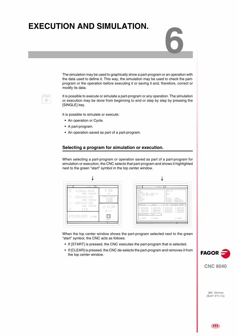
111
CNC 8040
·MC· OPTION(SOFT V11.1X)
6EXECUTION AND SIMULATION.
The simulation may be used to graphically show a part-program or an operation withthe data used to define it. This way, the simulation may be used to check the part-program or the operation before executing it or saving it and, therefore, correct ormodify its data.
It is possible to simulate or execute:
• An operation or Cycle.
• A part-program.
• An operation saved as part of a part-program.
Selecting a program for simulation or execution.
When selecting a part-program or operation saved as part of a part-program forsimulation or execution, the CNC selects that part-program and shows it highlightednext to the green "start" symbol in the top center window.
When the top center window shows the part-program selected next to the green"start" symbol, the CNC acts as follows:
• If [START] is pressed, the CNC executes the part-program that is selected.
• If [CLEAR] is pressed, the CNC de-selects the part-program and removes it fromthe top center window.
It is possible to execute or simulate a part-program or any operation. The simulationor execution may be done from beginning to end or step by step by pressing the[SINGLE] key.

Operating manual
CNC 8040
6.
EX
EC
UT
ION
AN
D S
IMU
LA
TIO
N.
Sim
ulat
ing
or e
xecu
ting
an o
pera
tion
or c
ycle
.
·MC· OPTION(SOFT V11.1X)
112
6.1 Simulating or executing an operation or cycle.
All the operations or cycles have 2 work modes; execution and editing.
Simulation.
Execution.
An operation or cycle can only be executed in the cycle execution mode.
The operation or cycle cannot be executed when the cycle editing mode is selected.Press [ESC] to quit the editing mode and switch to execution mode.
Editing mode Execution mode
The operation or cycle may be simulated in both work modes. To do that, press the[GRAPHICS] key. The CNC shows the graphic screen of the M model.
Press [START] to execute an operation or cycle.

Operating manual
CNC 8040
EX
EC
UT
ION
AN
D S
IMU
LA
TIO
N.
Sim
ulat
ing
or e
xecu
ting
a pa
rt-p
rogr
am.
6.
·MC· OPTION(SOFT V11.1X)
113
6.2 Simulating or executing a part-program.
Proceed as follows to simulate or execute a part-program:
1. Press [P.PROG] to access the list of part-programs stored.
2. Select on the left column the program to be simulated or executed.
Press [GRAPHICS] to simulate the part-program and [START] to execute it. Whenexecuting a program, the CNC executes the initial subroutine 9998 and the finalsubroutine 9999.
If an error occurs in a cycle during simulation or execution, when accessing the listof programs again, the cursor will be placed on the cycle that came up with the error.When program 999998 is displayed on the screen or the error is not an executionerror, the cursor will go to the beginning or to the end of the program depending onits length.
6.2.1 Simulating or executing a portion of a part-program.
Proceed as follows to simulate or execute a portion of a part-program:
1. Press [P.PROG] to access the list of part-programs stored.
2. Select the program from the left column and the operation (on the right column)from which to begin executing or simulating the part program.
Press [GRAPHICS] to simulate the selected portion and [START] to execute it. Whenexecuting a portion of a program, the CNC does not execute the initial subroutine9998, but it executes the final subroutine 9999. If the program is executed from thefirst operation on, it executes both subroutines.
Operating manual
CNC 8040
6.
EX
EC
UT
ION
AN
D S
IMU
LA
TIO
N.
Sim
ulat
ing
or e
xecu
ting
an o
pera
tion
that
has
bee
n sa
ved.
·MC· OPTION(SOFT V11.1X)
114
6.3 Simulating or executing an operation that has beensaved.
Proceed as follows to simulate or execute an operation that has been saved as a partof program:
1. Press [P.PROG] to access the list of part-programs stored.
2. Select the program that contains it from the left column and the operation to besimulated or executed from the right column.
3. Press the [RECALL] key.
Press [GRAPHICS] to simulate the operation and [START] to execute it.

Operating manual
CNC 8040
EX
EC
UT
ION
AN
D S
IMU
LA
TIO
N.
Exe
cutio
n m
ode.
6.
·MC· OPTION(SOFT V11.1X)
115
6.4 Execution mode.
During execution, both screens show (in the top center window) the number of theprogram and the number of the cycle being executed. However, when detecting anRPT or GOTO instruction, the cycle number will disappear.
When pressing [START] to execute an operation or part-program, the CNC showsthe standard screen of the MC mode.
When pressing the two-color key, the CNC shows the special screen of the MC mode.
Once the operation or part has been selected, it may be executed as often as desired;to do that, once the execution has finished, pressed the [START] again.
To interrupt the execution, press [STOP]. Once the execution has been interrupted,a tool change may be done. See "6.4.1 Tool inspection." on page 116.
While executing an operation or a part, the [GRAPHICS] key may be pressed toaccess the graphics display mode.
Operating manual
CNC 8040
6.
EX
EC
UT
ION
AN
D S
IMU
LA
TIO
N.
Exe
cutio
n m
ode.
·MC· OPTION(SOFT V11.1X)
116
6.4.1 Tool inspection.
The PLC mark M5050 "TOOLINSP" determines when tool inspection is enabled.
Once tool inspection has been selected, it is possible:
• To move the axes to the tool change point.
• To select another tool.
• To modify the tool values.
• To resume program execution.
To move the axes to the tool change point.
To move the axes with the handwheels or the jog keypad to the point where the toolwill be changed.
To select another tool.
The standard screen of the MC mode must be selected in order to be able to makea tool change.
Press the [T] key. The CNC highlights the tool number.
Modifying the tool values (dimensions and geometry).
It is possible to modify the dimensions of the tool (offsets I, K to compensate for wear)or the values for tool geometry.
Press the [ESC] key to exit this screen and go back to the previous one (still in toolinspection).
Resuming program execution.
There may be 2 cases; either only one axis moved or several did.
• Only one axis moved.
The CNC repositions it and resumes the execution.
TOOLINSP=0 Tool inspection is possible after pressing [STOP].
TOOLINSP=1 Pressing [STOP] interrupts the execution of the program. To movethe axes and do a tool inspection, press the [T] key once theexecution of the program has been interrupted.
Type in the number of the tool to be selected and press [START] so the CNC selectsthe new tool. The CNC will manage the tool change.
Press the key associated with tool calibration. The CNC shows the screen for toolcalibration.
Press the [START] key to resume program execution. The CNC will reposition thetool by moving it to the point where tool inspection began.

Operating manual
CNC 8040
EX
EC
UT
ION
AN
D S
IMU
LA
TIO
N.
Exe
cutio
n m
ode.
6.
·MC· OPTION(SOFT V11.1X)
117
• Several axes moved.
The CNC will show a window with the following options to choose the order theaxes will be repositioned.
PLANE The axes of the X-Y plane move at the same time.
Y-X When moving the axes of the plane, the Y axis moves first and thenthe X.
X-Y When moving the axes of the plane, the X axis moves first and thenthe Y.
Z Move the Z axis.
For example, to move first the Z axis, then the Y and finally the X axis, select [Z] [Y-X].

Operating manual
CNC 8040
6.
EX
EC
UT
ION
AN
D S
IMU
LA
TIO
N.
Gra
phic
rep
rese
ntat
ion.
·MC· OPTION(SOFT V11.1X)
118
6.5 Graphic representation.
The operation manual, M model, "Graphics" section of the "Execution / Simulation"chapter describes how to use the graphics display. However, here is a briefdescription of the softkeys.
Type of graphic.
Display area.
With this option it is possible to re-define the display area by defining the maximumand minimum values for each axis.
Use the [ ][ ] keys to select the maximum and minimum values. Once all the datahas been defined, press [ENTER].
When selecting a new display area, the CNC clears the screen and shows the axesor the part unmachined.
When pressing the [GRAPHICS] key, the CNC shows the graphics screen of the Mmodel. To quit the graphics mode, press either [GRAPHICS] or [ESC].
During simulation, the top center window shows the number of the program and thenumber of the cycle being executed. However, when detecting an RPT or GOTOinstruction, the cycle number will disappear.
3D It draws the part in three dimensions.
XY, XZ, YZ They draw the part in the selected plane.
COMBINED VIEW It divides the screen in four quadrants and draws the graphcorresponding to each plane XY, XZ, YZ and the three-dimensional graph.
TOP VIEW It draws a top view (XY plane) with different shades of gray thatindicate the depth of the part.
It also displays the XZ and YZ sections for the areas shown bythe indicators of the top view (XY plane).
SOLID It shows a three-dimensional block that will be “machined” asthe part-program is being run.
The display area cannot be changed while executing or simulating the part. If it is,interrupt the execution or simulation by pressing the [STOP] key.

Operating manual
CNC 8040
EX
EC
UT
ION
AN
D S
IMU
LA
TIO
N.
Gra
phic
rep
rese
ntat
ion.
6.
·MC· OPTION(SOFT V11.1X)
119
Zoom.
With this option, it is possible to enlarge or reduce the graphics display area.
It shows a window superimposed on the current graphics and another one over thedrawing at the lower right-hand side of the screen. These new windows indicate thenew display area being selected.
Use the [ ][ ][ ][ ] keys to move the window around, the softkeys "ZOOM+""ZOOM-" to enlarge or shrink its size and press [ENTER] for those new values to beassumed.
Every time a new display area is selected, the CNC keeps the current graphicrepresentation. It does not delete it.
Graphic parameters.
• Simulation speed.
Select on the top right side of the screen the percentage of simulation speed tobe applied.
Use the [ ][ ] keys to select the percentage and press [ENTER] for the CNCto assume that value.
• Tool path colors.
It only makes sense in line graphics (not in solid ones). It lets you choose the colorsto represent rapid traverse, the tool path without compensation, the tool path withcompensation and threading.
Use the [ ][ ] keys to select, on the right side of the screen, the type of path anduse the [ ][ ] keys to select the color to be applied.
Press [ENTER] for the CNC to assume those values.
• Colors of solid.
It only makes sense in solid graphics (not in line graphics). It lets you use the colorsto represent the cutter, the part, the axes and the clamps.
Use the [ ][ ] keys to select, on the right side of the screen, the type of path anduse the [ ][ ] keys to select the color to be applied.
Press [ENTER] for the CNC to assume those values.
Clear Screen.
When selecting this option, the CNC clears the screen and shows the axes or thepart unmachined.
When pressing [START] to resume or re-start the execution or simulation, it deletesthe current graphic representation and starts a new one with the new values.
The zoom function cannot be used while executing or simulating the part. If it is,interrupt the execution or simulation by pressing the [STOP] key.
The screen cannot be cleared while executing or simulating the part. If it is, interruptthe simulation by pressing the [STOP] key.
Operating manual
CNC 8040
6.
EX
EC
UT
ION
AN
D S
IMU
LA
TIO
N.
Gra
phic
rep
rese
ntat
ion.
·MC· OPTION(SOFT V11.1X)
120
Starting graphic simulation.
During graphic simulation, the CNC takes into account the simulation speed and theposition of the feedrate override switch (FEED 0%-120%).
When selecting a new simulation speed, the CNC applies 100% of it regardless ofthe position of the switch. Once the switch is turned, the CNC begins to apply theselected %.
To interrupt the simulation, press [STOP].
ISO.
In the conversational mode of the CNC, it is possible to generate an ISO-codedprogram with some basic G functions as well as M and T functions from an operation(cycle) or on a part-program.
To enable this feature, set general machine parameter ISOSIMUL (P183) with avalue other than zero. This parameter identifies the number of the ISO programgenerated in user RAM memory.
The program generated from the conversational program is an ISO-coded programcreated in RAM memory. This program may be later edited, copied or executed atthe CNC itself.
To generate the ISO program, use the simulation in conversational mode through the"GRAPHICS" key. This can be done in a whole program on the PPROG screen orin any of the particular TC or MC cycles.
Once inside the graphic simulation screen, the ISO generation maybe selected usingthe <ISO> softkey. Then, pressing [CYCLE START] will generate the programdefined by machine parameter ISOSIMUL (that will only contain ISO instructions)while it simulates it graphically.
When generating that program, parametric programming, rounding (G36), tangentialentry (G37), tangential output (G38), chamfer (G39) and path tangent to previouspath (G8) are resolved and generated only using G1, G2 and G3 blocks.
If the program already exists, it will be deleted without requesting confirmation. If thegenerated program exceeds the available user memory, the CNC will issue thecorresponding error message, but it will keep in memory the portion of the ISOprogram generated so far.
Once the type of graphics, the display area, the graphic parameters, etc have beenselected, press the [START] key to start graphic simulation.
To quit the simulation mode, press either [GRAPHICS] or [ESC].

Operating manual
CNC 8040
EX
EC
UT
ION
AN
D S
IMU
LA
TIO
N.
Gra
phic
rep
rese
ntat
ion.
6.
·MC· OPTION(SOFT V11.1X)
121
Description of the functions used to generate an ISO-coded program:
The ISO-coded program is mainly generated to control axes. It provides informationof the moving conditions and indications on feedrate using the following set offunctions
• G functions: Motion preparatory functions to determe the geometry and workconditions.
Rigid tapping cycles G84 (mill) and G86 (lathe) only generate the equivalent ISOblock.
• "F" and "S" functions: Functions to control the feedrate of the axes and thespindle turning speed.
• T and D functions: Tool control functions.
If the T function has an associated subroutine, the blocks of this subroutine areignored when generating the program set by g.m.p. ISOSIMUL (P183).
• M function: Complementary or auxiliary functions.
If the M functions have an associated subroutine, the blocks of this subroutineare ignored when generating the program set by g.m.p ISOSIMUL (P183).
Function Meaning
G2 (G3) G6 X Y I J In the circular interpolation, the center will beprogrammed with respect to the origin, notreferred to the starting point of the circle.

CNC 8040
6.
EX
EC
UT
ION
AN
D S
IMU
LA
TIO
N.
·MC· OPTION(SOFT V11.1X)
122
Operating manual