Embed Size (px)
Citation preview

Clock and Asynchronous Signals
Z. Jerry ShiComputer Science and Engineering
University of ConnecticutUniversity of Connecticut
Thank John Wakerly for providing his slides and figures.

Functional timing

Delays in state machines
Setup-time margin = t_clk – t_ffpd_max – t_comb_max – t_setup > 0Hold-time margin = t_ffpd_min + t_comb_min – t_hold > 0
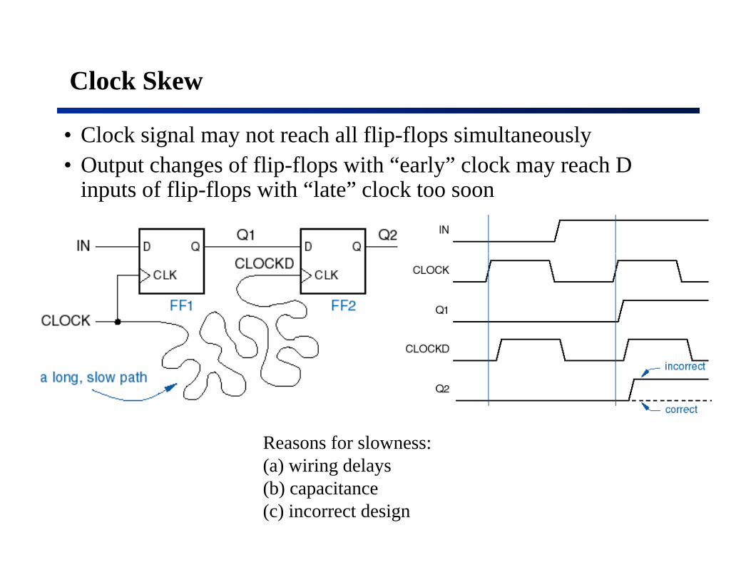
Clock Skew
• Clock signal may not reach all flip-flops simultaneously• Output changes of flip-flops with “early” clock may reach D
inputs of flip-flops with “late” clock too soon
Reasons for slowness:(a) wiring delays( ) g y(b) capacitance(c) incorrect design
Clock-skew calculation
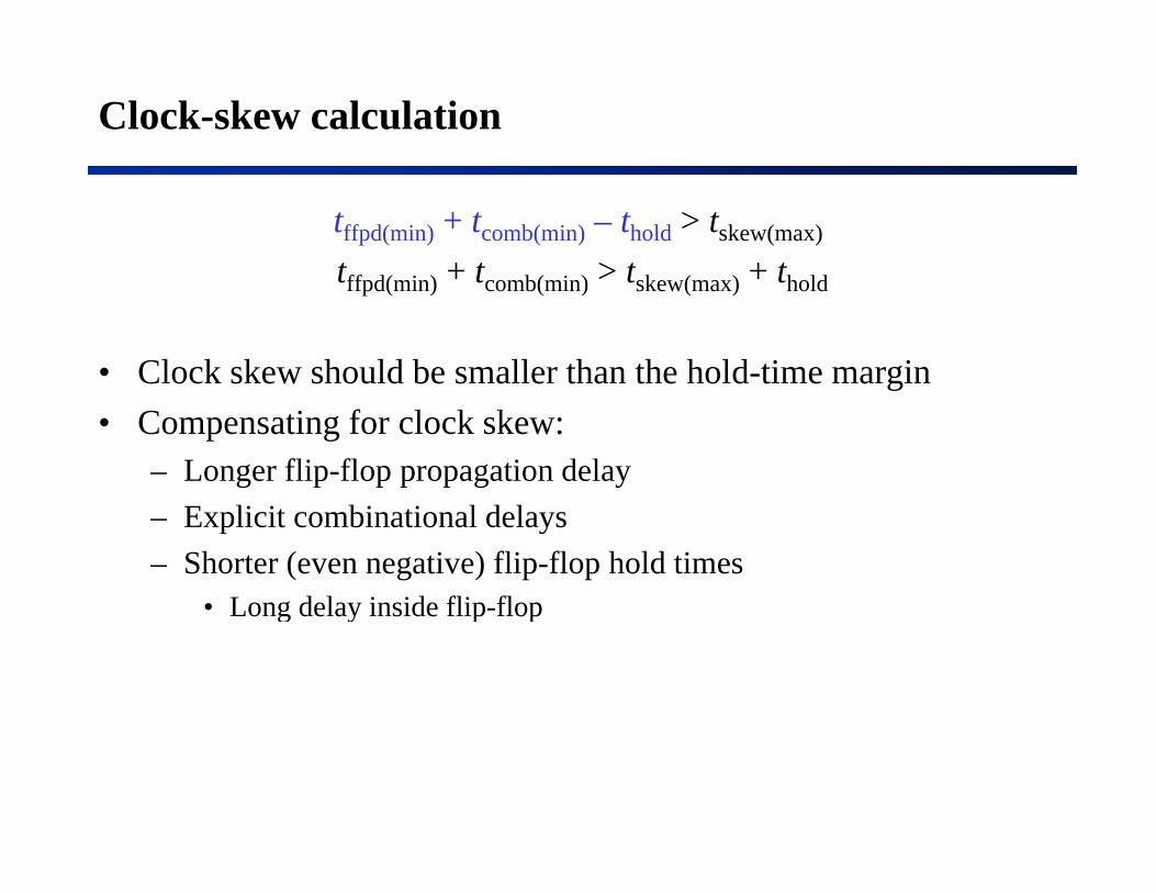
tffpd(min) + tcomb(min) – thold > tskew(max)
tff d( i ) + t b( i ) > t k ( ) + th ldtffpd(min) + tcomb(min) > tskew(max) + thold
• Clock skew should be smaller than the hold-time marging• Compensating for clock skew:
– Longer flip-flop propagation delay– Explicit combinational delays– Shorter (even negative) flip-flop hold times
• Long delay inside flip-flopLong delay inside flip flop

Example of bad clock distribution

Clock distribution in ASICs
• This is what a typical ASIC router will do if you don’t lay out• This is what a typical ASIC router will do if you don t lay out the clock by hand.

“Clock-tree” solution
• Often laid out by hand (H-tree)y ( )• Wide,fast metal (low R ==> fast RC time constant)

Gating the clock
• Definitely a no no• Definitely a no-no– Glitches possible if control signal (CLKEN) is generated by
the same clock– Excessive clock skew in any case

If you really must gate the clock...

Control unit and data unit
• Divide large state machines into smaller machines• Data unitData unit
– Data processing• Storing, moving, combing, etc.
– Registers, specialized functions (adder, shifter), memory• Control unit
Starting stopping actions in data units– Starting, stopping actions in data units– Testing conditions– Deciding what to do next

Synchronous System Structure
Everything is clocked by the same commonsame, common clock

Typical synchronous-system timing
• Outputs have one complete clock period to propagate to inputs• Must take into account flip-flop setup times at next clock period

Simplified PowerPC core block diagram
InstructionU it MMUUnit
Load/Store Unit
LSU
GPR File
ALU

Abstract view of instruction execution unit for MIPS

Datapath
n
n
Register
File
Mul ALU Shifter
nn

Asynchronous inputs
• Not all inputs are synchronized with the clock• Examples:Examples:
– Keystrokes– Sensor inputs– Data received from a network (transmitter has its own clock)
• Inputs must be synchronized with the system clock before being applied to a synchronous systemsystem clock before being applied to a synchronous system

A simple synchronizer

Only one synchronizer per input

Even worse
• Combinational delays to the two synchronizers are likely to be different

The way to do it
O h i i• One synchronizer per input• Carefully locate the synchronization points in a system• But still a problem -- the synchronizer output may becomeBut still a problem the synchronizer output may become
metastable when setup and hold time are not met

Synchronizer failure
• Synchronizer failure: a system uses a synchronizer output while the output is still in the metsastable statep– Use input signals that meet the published specification– Wait “long enough” so FF comes out of metastability on its own
• Metastability resolution time – The maximum time that the output can remain metastable without
causing synchronizer failure, e.g., g y , g ,tr = tclk – tcomb – tsetup
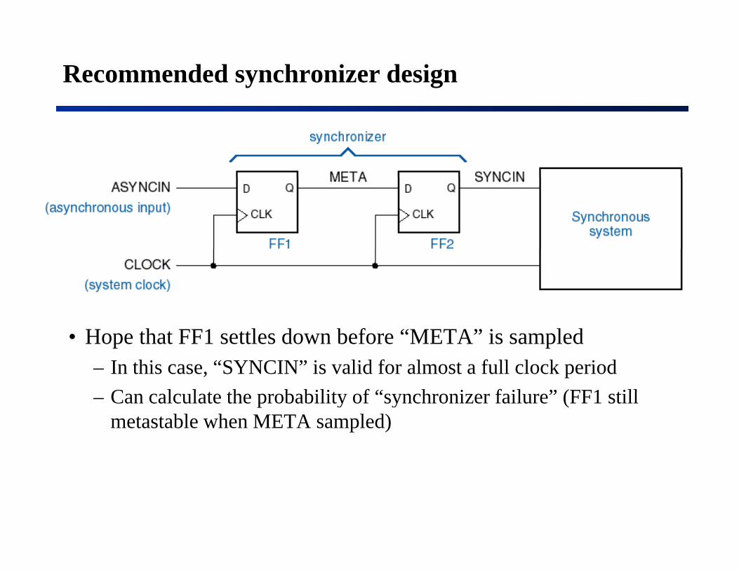
Recommended synchronizer design
• Hope that FF1 settles down before “META” is sampled– In this case, “SYNCIN” is valid for almost a full clock period
C l l t th b bilit f “ h i f il ” (FF1 till– Can calculate the probability of “synchronizer failure” (FF1 still metastable when META sampled)

Metastability decision window

Metastability resolution time

Flip-flop metastable behavior
• Probability of flip-flop output being in the metastable state is an exponentially decreasing function of tr (time since clock edge, a.k.a. “resolution time”)
• Mean time between synchronization failures (MTBF):
etMTBFrt
=/
)(τ
where
afTtMTBF r ⋅⋅
=0
)(
τ and T0 are parameters for a particular flip-flopf is the clock frequency, anda is the number of asynchronous transitions / sec y

Typical flip-flop metastability parameters
/
afTetMTBF
rt
r ⋅⋅=
0
/
)(τ
MTBF = 1000 yrs.f 25 MHf = 25 MHza = 100 KHztr = ?
Is 1000 years enough?
• If MTBF = 1000 years and you ship 52,000 copies of the product, then some system experiences a mysterious failure every weeky p y y
• Real-world MTBFs must be much higher• How to get better MTBFs?
– Use faster flip-flops• But clock speeds keep getting faster, thwarting this approach
– Wait for multiple clock ticks to get a longer metastabilty resolution– Wait for multiple clock ticks to get a longer metastabilty resolution time• Waiting longer usually doesn’t hurt performance
l h i i i l “ d i ” h d h k• …unless there is a critical “round-trip” handshake

Multiple-cycle synchronizer
• Clock-skew problemp

Deskewed multiple-cycle synchronizer
• Necessary in really high-speed systems• DSYNCIN is valid for almost an entire clock period