Embed Size (px)
Citation preview
Clinical Manual ®
®
®
®
ClinicalManual
TM

© 2000 Respironics, Inc. All rights reserved.
BiPAP systems are the subject of one or more of U.S. Patents #5148802, #5239995, #5313937,#5433193, Canadian Patent #2, 024, 477, European Patent #EP0425092, German Patent #69021681.5-08, and other pending U.S. and foreign patents. BiPAP, Harmony, Plateau, Whisper Swivel, ComfortFlap, Spectrum, Monarch, Softcap, Quick Clip, Oasis, and Auto-Trak Sensitivity are registered trade-marks of Respironics, Inc.

i
ContentsChapter 1: Introduction .......................................................................................... 1-11.1 Vision Overview................................................................................................. 1-11.2 Manual Overview ............................................................................................... 1-21.3 Symbol Key........................................................................................................ 1-31.4 Product Support .................................................................................................. 1-4Chapter 2: Warnings, Cautions, and Notes ........................................................... 2-12.1 Warnings............................................................................................................. 2-12.3 Notes................................................................................................................... 2-42.2 Cautions.............................................................................................................. 2-42.4 Important Information Concerning CO2 Rebreathing ........................................ 2-52.5 Intended Use....................................................................................................... 2-62.6 Contraindications ............................................................................................... 2-62.7 Patient Cautions.................................................................................................. 2-62.8 Invasive Applications ......................................................................................... 2-7Chapter 3: Principles of Operation ........................................................................ 3-13.1 Introduction ........................................................................................................ 3-13.2 Design and Operation ......................................................................................... 3-2
3.2.1 ELECTRONICS SYSTEM ......................................................................................................... 3-23.2.2 OXYGEN MODULE ............................................................................................................... 3-43.2.3 PNEUMATIC SYSTEM............................................................................................................. 3-53.2.4 STANDBY MODE .................................................................................................................. 3-63.2.5 FLOW ANALYSIS .................................................................................................................. 3-7
3.3 BiPAP® Auto-Trak Sensitivity™........................................................................ 3-83.3.1 LEAK TOLERANCE ............................................................................................................... 3-83.3.2 SENSITIVITY ........................................................................................................................ 3-9
3.4 Description of System Alarms.......................................................................... 3-123.4.1 CHECK VENTILATOR .......................................................................................................... 3-123.4.2 VENTILATOR INOPERATIVE .................................................................................................. 3-123.4.3 EXHALATION PORT ALARM ................................................................................................. 3-12
3.5 User Interface ................................................................................................... 3-133.6 Exhalation Port Test ......................................................................................... 3-14

ii
Chapter 4: Controls and Displays .......................................................................... 4-14.1 Overview ............................................................................................................ 4-14.2 Patient Circuit Connections ................................................................................ 4-24.3 Adjustment Knob ............................................................................................... 4-24.4 Soft Keys ............................................................................................................ 4-3
4.4.1 SOFT KEY OPERATION............................................................................................................ 4-34.4.2 SOFT KEY DESCRIPTORS...................................................................................................... 4-3
4.5 Hard Keys—Operational .................................................................................... 4-44.5.1 MONITORING HARD KEY ..................................................................................................... 4-44.5.2 PARAMETERS HARD KEY ..................................................................................................... 4-54.5.3 MODE HARD KEY ............................................................................................................... 4-54.5.4 ALARMS HARD KEY ............................................................................................................ 4-5
4.6 Hard Keys—Graph Control ............................................................................... 4-64.6.1 SCALE HARD KEY ............................................................................................................... 4-64.6.2 FREEZE/UNFREEZE HARD KEY ............................................................................................. 4-6
4.7 Hard Keys—Alarm ............................................................................................ 4-74.7.1 ALARM SILENCE HARD KEY ................................................................................................ 4-74.7.2 ALARM RESET HARD KEY ................................................................................................... 4-7
4.8 Ventilator Warning Indicators ............................................................................ 4-84.8.1 VENTILATOR INOPERATIVE INDICATOR.................................................................................... 4-84.8.2 CHECK VENTILATOR INDICATOR ............................................................................................ 4-8
4.9 Graphic Display.................................................................................................. 4-94.9.1 MODE/MESSAGE AREA ........................................................................................................ 4-94.9.2 GRAPHIC DISPLAY AREA ...................................................................................................... 4-94.9.3 DATA DISPLAY AREA ........................................................................................................... 4-94.9.4 DATA VALUES ................................................................................................................... 4-10
4.10 Rear Panel ........................................................................................................ 4-134.10.1 POWER ENTRY MODULE..................................................................................................... 4-134.10.2 START/STOP SWITCH .......................................................................................................... 4-134.10.3 OXYGEN MODULE ............................................................................................................. 4-144.10.4 DIAGNOSTIC CONNECTOR................................................................................................... 4-144.10.5 NURSE CALL/REMOTE ALARM CONNECTOR......................................................................... 4-144.10.6 GROUNDING STUD ............................................................................................................. 4-14
4.11 Internal Alarm Battery...................................................................................... 4-144.12 Parameter Retention ......................................................................................... 4-144.13 Options............................................................................................................. 4-15Chapter 5: Operational Flow Charts ..................................................................... 5-15.1 Start-up Flow Chart ............................................................................................ 5-15.2 Change Mode Flow Chart .................................................................................. 5-25.3 Modify Parameters Flow Chart .......................................................................... 5-35.4 Modify Alarms Flow Chart ................................................................................ 5-4
iii
Chapter 6: Setting Up and Starting the Vision System ........................................ 6-16.1 Setting Up the Vision System............................................................................. 6-16.2 Starting the Vision System ................................................................................. 6-36.3 Changing the Language...................................................................................... 6-7Chapter 7: Performance Verification ..................................................................... 7-1Chapter 8: CPAP Mode ........................................................................................... 8-18.1 Overview ............................................................................................................ 8-18.2 Changing to the CPAP Mode ............................................................................. 8-28.3 Modifying Parameters in the CPAP Mode ......................................................... 8-48.4 Modifying Alarm Parameters ............................................................................. 8-6Chapter 9: S/T Mode ............................................................................................... 9-19.1 Overview ............................................................................................................ 9-19.2 Changing to the S/T Mode ................................................................................. 9-39.3 Modifying Parameters in the S/T Mode ............................................................. 9-79.4 Modifying Alarm Parameters ............................................................................. 9-9Chapter 10: Options Screen .................................................................................. 10-110.1 Overview .......................................................................................................... 10-110.2 Using the Options Screen ................................................................................. 10-2
10.2.1 ERROR MESSAGES............................................................................................................. 10-210.2.2 TESTING THE ALARMS ........................................................................................................ 10-310.2.3 DISPLAYING SYSTEM INFORMATION ..................................................................................... 10-410.2.4 CHANGING THE GRAPHIC DISPLAY ...................................................................................... 10-410.2.5 RESETTING THE TIME AT PRESSURE..................................................................................... 10-510.2.6 ADJUSTING THE DISPLAY .................................................................................................... 10-510.2.7 TOTAL OPERATING TIME .................................................................................................... 10-610.2.8 RETURNING TO THE MONITORING SCREEN ........................................................................... 10-6
Chapter 11: Modifying Graphic Displays ........................................................... 11-111.1 Overview .......................................................................................................... 11-111.2 Modifying the Display Graph Scales ............................................................... 11-2
11.2.1 MODIFYING THE SCALES .................................................................................................... 11-211.2.2 RETURNING TO THE MONITORING SCREEN ........................................................................... 11-4
11.3 Summary of Display Graph Scale Ranges and Increments.............................. 11-411.4 Freezing and Unfreezing the Graphs................................................................ 11-5Chapter 12: Alarms and Troubleshooting ........................................................... 12-112.1 Alarms Overview ............................................................................................. 12-1
12.1.1 ALARM INDICATIONS.......................................................................................................... 12-212.1.2 ALARM SILENCE AND RESET .............................................................................................. 12-2
12.2 Alarms .............................................................................................................. 12-312.3 Mask Discomfort and Corrective Actions ...................................................... 12-10
iv
Chapter 13: Oxygen Delivery with the Vision Ventilator................................... 13-113.1 Overview .......................................................................................................... 13-113.2 Oxygen Module ................................................................................................ 13-2Chapter 14: Cleaning and Routine Maintenance ............................................... 14-114.1 Overview .......................................................................................................... 14-114.2 Cleaning the Vision Unit .................................................................................. 14-1
14.2.1 CLEANING THE FRONT PANEL ............................................................................................. 14-114.2.2 CLEANING THE ENCLOSURE................................................................................................ 14-1
14.3 Replacing the Inlet Filter .................................................................................. 14-114.4 Changing the System Fuses.............................................................................. 14-314.5 Voltage Selection .............................................................................................. 14-314.6 Preventive Maintenance ................................................................................... 14-314.7 Internal Battery Maintenance ........................................................................... 14-4
14.7.1 BATTERY FUNCTION ........................................................................................................... 14-414.7.2 LOW BATTERY CONDITION ................................................................................................. 14-414.7.3 CHARGING THE INTERNAL BATTERY ..................................................................................... 14-5
Chapter 15: Accessories ........................................................................................ 15-115.1 Circuit Configurations ...................................................................................... 15-1
15.1.1 STANDARD NONINVASIVE CIRCUIT ...................................................................................... 15-215.1.2 NONINVASIVE CIRCUIT WITH HEATED HUMIDIFIER ................................................................ 15-215.1.3 INVASIVE CIRCUIT .............................................................................................................. 15-3
15.2 Circuits and Accessories ................................................................................... 15-415.3 Exhalation Ports ................................................................................................ 15-415.4 Masks and Related Accessories ........................................................................ 15-415.5 Humidifiers....................................................................................................... 15-4Chapter 16: Specifications .................................................................................... 16-1
ENVIRONMENTAL .......................................................................................................................... 16-1PHYSICAL ..................................................................................................................................... 16-1ELECTRICAL ................................................................................................................................. 16-1PRESSURE..................................................................................................................................... 16-1CONTROL ACCURACY .................................................................................................................... 16-2DISPLAY ACCURACY...................................................................................................................... 16-2TRIGGER...................................................................................................................................... 16-2OXYGEN MODULE INLET ............................................................................................................... 16-2INTERNAL BATTERIES .................................................................................................................... 16-2INLET FILTER ................................................................................................................................ 16-2NURSE CALL /REMOTE ALARM CONNECTOR.................................................................................... 16-2CONTROL RANGES & INCREMENTS................................................................................................. 16-3DISPLAY RANGES & I NCREMENTS.................................................................................................. 16-4CO
2 REBREATHING CHARTS—NON-INVASIVE APPLICATIONS............................................................ 16-5
CO2 REBREATHING CHARTS—INVASIVE APPLICATIONS.................................................................... 16-7

1-1
BiPAP Vision Clinical Manual
Chapter 1: Introduction
1.1 Vision Overview The BiPAP® Vision ventilator, shown in Figure 1-1, is a microprocessor-controlled positive pressure ventilatory assist system. The Vision systemincorporates a user interface with multifunction keys, real time graphic dis-plays, and integral patient and system alarms. Figure 1-1 shows the contents ofthe Vision package.
The system operates in the Continuous Positive Airway Pressure (CPAP) andPressure Support (S/T) modes.
The Vision ventilator contains a variety of integrated safety and self-diagnosticfeatures. All system functions are checked at start-up and during operation.
Pressure regulation is achieved by monitoring proximal airway pressure andadjusting flows accordingly to ensure that the set pressure equals the proximalpressure.
MODE: S/T MONITORING
IPAP
15
cm H2O
cm H2O
EPAP
6
Rate
Options
12
BPM
%O2
55
%
VT 1000
ml
PIP 15 cm H
2O
MinVent 14 L/min
PS = 9 cm H2O
P (cm H2O)
Vol (ml)
Flow (L/min)
The First Name In Innovative Respiratory Care
ClinicalManual
Vision Ventilator Vision Clinical Manual
Figure 1-1. Contents of the Vision Package.
NOTE: This manual is for use only in the United States and its territories.
1-2
BiPAP Vision Clinical Manual
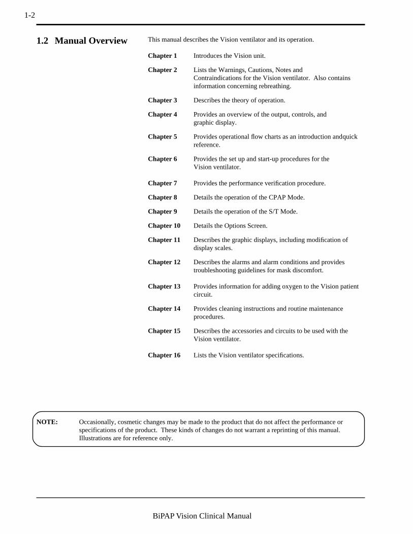
1.2 Manual Overview This manual describes the Vision ventilator and its operation.
Chapter 1 Introduces the Vision unit.
Chapter 2 Lists the Warnings, Cautions, Notes andContraindications for the Vision ventilator. Also containsinformation concerning rebreathing.
Chapter 3 Describes the theory of operation.
Chapter 4 Provides an overview of the output, controls, andgraphic display.
Chapter 5 Provides operational flow charts as an introduction andquickreference.
Chapter 6 Provides the set up and start-up procedures for theVision ventilator.
Chapter 7 Provides the performance verification procedure.
Chapter 8 Details the operation of the CPAP Mode.
Chapter 9 Details the operation of the S/T Mode.
Chapter 10 Details the Options Screen.
Chapter 11 Describes the graphic displays, including modification ofdisplay scales.
Chapter 12 Describes the alarms and alarm conditions and providestroubleshooting guidelines for mask discomfort.
Chapter 13 Provides information for adding oxygen to the Vision patientcircuit.
Chapter 14 Provides cleaning instructions and routine maintenanceprocedures.
Chapter 15 Describes the accessories and circuits to be used with theVision ventilator.
Chapter 16 Lists the Vision ventilator specifications.
NOTE: Occasionally, cosmetic changes may be made to the product that do not affect the performance orspecifications of the product. These kinds of changes do not warrant a reprinting of this manual.Illustrations are for reference only.

1-3
BiPAP Vision Clinical Manual
1.3 Symbol Key The following symbols are used on the Vision unit:
Ventilator Inoperative
Check Ventilator
Audible Alarm Silence
Alarm Reset
Symbol Meaning
Adjustment
MONITORING
PARAMETERS
ALARMS
SCALE
FREEZE/UNFREEZE
PRESSURE
MAIN POWER
Display the Monitoring Screen
Display the Parameters Screen
Display the Change Alarms Screen
Adjust the graphic scales
Freeze or Unfreeze the graphic display
Attachment port for proximal pressure line
Indicates unit is connected to power source
Type BF
Fuse
Attention, consultaccompanying documents
Vent Inop
Check Vent
1-4
BiPAP Vision Clinical Manual
1.4 Product Support You may contact Respironics, Inc. with any questions or for product support atthe following location:
2-1
BiPAP Vision Clinical Manual
Chapter 2: Warnings, Cautions, and Notes
2.1 Warnings
WARNING: Indicates the possibility of injury to the patient or the operator.CAUTION: Indicates the possibility of damage to the device.NOTE: Places emphasis on an operating characteristic.
• This manual serves as a reference. The instructions in this manual arenot intended to supersede the institution’s protocol regarding the use ofthe Vision ventilator.
• The operator must verify that all gas connectors have color codes inaccordance with EN 60601-1/A13:1995.
• The following BiPAP Vision System operational characteristics differfrom conventional ventilators as described in ASTM F 1100 andshould be reviewed before use:
• The BiPAP Vision provides continuous positive airway pressure(CPAP) and positive pressure ventilation and is indicated forassisted ventilation. This system does not provide ventilationwith guaranteed tidal volume delivery. Patients requiringventilation at predetermined tidal volumes are not candidates forpressure support or pressure-limited ventilation.
• The BiPAP Vision requires an intentional leak port instead of anactively controlled exhalation valve to remove exhaled gasesfrom the circuit. Therefore, specific masks and circuits using anintentional leak port are required for normal operation. Thepressurized air from the Vision causes a continuous flow of air toexhaust from the leak port, flushing exhaled gas from the circuit.The machine should be turned on and the intentional leak portshould be checked, both visually and using the exhalation porttest, before application. Use only Respironics-specified circuitaccessories.
• The continuous flow of air through the leak port flushes exhaledgases from the circuit. The ability to completely exhaust exhaledgas from the circuit is dependent upon the EPAP setting and I:Eratio. At low EPAP pressures or with short expiratory times (i.e.,high breathing rates) the leak rate through the intentional leakport may be inadequate to clear all exhaled gas from the circuit.Some rebreathing may occur.
• The Vision ventilator is an assist ventilator and is intended to augmentthe ventilation of a spontaneously breathing patient. It is not intendedto provide the total ventilatory requirements of the patient.
• The Vision ventilator is intended for use with a Respironics, Inc.patient circuit only. See Chapter 15 for approved patient circuitconfigurations and accessories.

2-2
BiPAP Vision Clinical Manual
Warnings (continued) • Proper operation of the Plateau™ Exhalation Valve or any otherexhalation port used with the BiPAP Vision must be regularly verifiedby inspection during use. Occlusion or partial occlusion of theexhalation port may result in asphyxia.
• To reduce the risk of contamination, a low resistance main flowbacteria filter must be placed in-line between the unit and the patient.
• All patient settings must be determined via appropriate assessment andmonitoring as determined by the prescribing physician. Deliveredpressures must be monitored at the patient connection with the unitcycling to validate pressure delivery.
• The Vision ventilator is not suitable for use in the presence of aflammable anesthetic mixture with air or with oxygen or nitrous oxide.
• Oxygen supports combustion. Oxygen should not be used whilesmoking or in the presence of an open flame.
• The functionality of this machine may be adversely affected by theoperation of high frequency (diathermy) equipment, defibrillators, orshort wave therapy equipment in the general vicinity.
• When the Oxygen Module is in use, the Vision ventilator will displaythe set oxygen concentration, which may not be the actual oxygenconcentration delivered to the patient. An external oxygen analyzer,added to the patient circuit, is recommended to monitor deliveredoxygen concentrations. See Chapter 13 for details concerning the useof oxygen with the Vision ventilator.
• When using the Oxygen Module, the operator must verify that thecorrect supply gas (O2) is connected to the O2 inlet.
• Do not use antistatic or electrically conductive hoses or tubing with theVision system.
• In the event of a power failure, an audible and visual alarm willactivate. Disconnect the Vision ventilator from the patient immedi-ately. As in most ventilators with passive exhalation ports, whenpower is lost, sufficient air will not be provided through the circuit andexhaled air may be rebreathed.
• The air flow for breathing produced by this device can be as much as10 °F (5.5 °C) higher than room temperature. Caution should beexercised if the room temperature is greater than 95 °F (35 °C).
• If the “Ventilator Inoperative” indicator illuminates, immediatelydiscontinue use, disconnect the patient circuit from the patient, andcontact Respironics, Inc. or an authorized service center.
• When the Vision ventilator is used with a humidifier, always positionthe humidifier lower than both the ventilator and the patient.
• Never attach oxygen tubing or any positive pressure source to thePressure Port on the front panel of the Vision ventilator.
2-3
BiPAP Vision Clinical Manual
• If you detect any unexplained changes in the performance or displaysof the Vision unit, seek the assistance of a Respironics-approvedservice person.
• Repairs and adjustments must be performed by Respironics-authorizedservice personnel ONLY. Service done by inexperienced, unqualifiedpersonnel or installation of unauthorized parts could cause injury,invalidate the warranty, or result in costly damage.
• To avoid electrical shock, disconnect the electrical supply beforechanging the fuses.
• For continued protection against risk of fire, replace fuses with thoseof the same type and rating only.
• Electrical cords and cables should be periodically inspected.
• To avoid electrical shock, unplug the Vision unit before cleaning it.
• The Nurse Call/Remote Alarm feature should be considered a backupto the Vision unit’s primary alarm system. Do not rely solely on theNurse Call/Remote Alarm feature.
Warnings (continued)
2-4
BiPAP Vision Clinical Manual
• Federal law (U.S.) restricts this device to sale by or on the order of aphysician.
• For pressure monitoring, use only the pressure tubing provided withthe Respironics circuit.
• Take care to avoid exposure of the Vision ventilator to temperatures ator near the extremes of those specified in Chapter 16. If exposure tosuch temperatures has occurred, the unit should be allowed to come toroom temperature before being turned on.
• The unit must be positioned on its base for proper operation.
• Always use an inlet filter when the Vision ventilator is operating.
• If using the Oxygen Module, do not exceed 100 psig oxygen supplypressure.
• Connections to the rear-panel diagnostic connector must be made byauthorized service personnel only.
• Before making any connection to the rear-panel nurse call connector,verify that the equipment being connected does not violate theelectrical specifications noted in Chapter 16.
• The Inspiratory Positive Airway Pressure (IPAP) and ExpiratoryPositive Airway Pressure (EPAP) controls are coupled. The unit willnot deliver an EPAP level that is higher than the set IPAP level.
• This device contains a rechargeable NiCAD battery which is used bythe alarms in the event of a power failure.
Additional Warnings, Cautions, and Notes are located throughoutthis manual.
2.2 Cautions
2.3 Notes

2-5
BiPAP Vision Clinical Manual
As with any ventilator used for mask ventilation, there are conditions underwhich patient CO2 rebreathing can occur while using the Respironics BiPAPVision ventilator. The following guidelines are provided to alert the user tothese conditions and to suggest methods for reducing the potential for CO2rebreathing. If rebreathing is a significant concern for a particular patient andthese guidelines are not sufficient to acceptably reduce the potential for CO2rebreathing, an alternative means of ventilation should be considered.
• Never leave the mask on the patient while the BiPAP Vision unit is notoperating. When the BiPAP Vision unit is not operating, the exhala-tion port (Respironics Disposable Circuit, Whisper Swivel, or PlateauExhalation Valve) does not allow sufficient exhaust to eliminate CO2from the circuit. Substantial CO2 rebreathing will occur.
• Patient monitoring should be performed initially and with each changein ventilator settings, circuit configuration, or patient condition todetect changes in respiratory status that may indicate excessive CO2rebreathing
• In general, as pressure decreases, the potential for CO2 rebreathingincreases. Lower pressures produce less flow through the exhalationport, which may not purge all CO2 from the circuit to preventrebreathing. Higher tidal volumes further increase the volume of CO2rebreathed by the patient in such circumstances. Testing performedwith the BiPAP Vision demonstrates that, under certain conditions,CO2 rebreathing can occur. See Chart 1 in Chapter 16.
• In general, as inspiratory time increases, the potential for CO2rebreathing increases. A higher inspiratory time decreases exhalationtime, allowing less CO2 to be purged from the circuit before the nextcycle. In such circumstances, higher tidal volumes further increase thevolume of CO2 rebreathed by the patient. Testing performed with theBiPAP Vision system demonstrates that under certain conditions, whenapproaching an I:E ratio of 1:1, CO2 rebreathing may occur. See Chart2 in Chapter 16.
• The Plateau Exhalation Valve reduces the level of CO2 rebreathingcompared to the level associated with the Whisper Swivel when lowpressures, long inspiratory time, and/or large tidal volumes are present.Accordingly, Respironics recommends the Plateau Exhalation Valvebe used instead of the Whisper Swivel to help reduce CO2 rebreathingin such situations. See Charts 1 and 2 in Chapter 16.
• Reducing deadspace can also lower potential CO2 rebreathing. Chart 3in Chapter 16 provides the approximate total volume of each of thepatient interface accessories that can be used with the BiPAP Visionventilator. Note that except for the Respironics Mouthpiece Adapter,the deadspace volume will be reduced when the mask is placed on thepatient’s face. Nevertheless, Chart 3 in Chapter 16 can be helpful inselecting an appropriate patient interface to reduce the amount ofdeadspace in the patient circuit. For comparison purposes, note thatthe testing which produced the data in Charts 1 and 2 was conductedusing a medium nasal mask.
2.4 Important Information Concerning CO 2 Rebreathing
2-6
BiPAP Vision Clinical Manual
2.5 Intended Use
2.6 Contraindications
2.7 Patient Cautions
The Vision ventilator is intended for use in a hospital or alternate care setting asan assist ventilator for the treatment of appropriate adult patients (30 Kg orgreater) with acute respiratory failure, acute or chronic respiratoryinsufficiency, or sleep apnea syndrome.
The use of the Vision ventilator is contraindicated on patients with severerespiratory failure without a spontaneous respiratory drive.
The use of the Vision ventilator for noninvasive positive pressure therapy maybe contraindicated on patients:
• incapable of maintaining life-sustaining ventilation in the event of abrief circuit disconnection or loss of therapy,
• unable to maintain a patent airway or adequately clearsecretions,
• at risk for aspiration of gastric contents,
• with acute sinusitis or otitis media,
• with a history of allergy or hypersensitivity to the mask materialswhere the risk from allergic reaction outweighs the benefit of ventila-tory assistance,
• with epistaxis, causing pulmonary aspiration of blood, or
• with hypotension.
• Advise the patient to immediately report any unusual chest discomfort,shortness of breath, or severe headache.
• If skin irritation or breakdown develops from the use of the mask,refer to Chapter 12 for appropriate action.
• The following are potential side effects of noninvasive positivepressure therapy:
Ear discomfortConjunctivitisSkin abrasions due to noninvasive interfacesAerophagia (gastric distention)
2-7
BiPAP Vision Clinical Manual
2.8 Invasive Applications The Vision ventilator may be used to provide invasive ventilation to appropri-ate patients. The following guidelines should be considered prior to use:
• The Vision ventilator is an assist ventilator and is intended to augmentthe ventilation of a spontaneously breathing patient. It is not intendedto provide the total ventilatory requirements of the patient.
• The Vision uses a single limb circuit and requires an intentional leakport instead of an actively controlled exhalation valve to removeexhaled gases from the circuit. Therefore, the Respironics invasivecircuit and accessories illustrated in Chapter 15 are required fornormal operation.
• A heated humidification system should always be used duringinvasive applications. See Chapter 15 for recommendations concern-ing humidification.
• In general, as pressure decreases, the potential for CO2 rebreathingincreases. Lower pressures produce less flow through the exhalationport, which may not purge all CO2 from the circuit to preventrebreathing. The Plateau™ Exhalation Valve reduces the level of CO2rebreathing compared to the level associated with the WhisperSwivel® when low pressures are present. Accordingly, if CO2rebreathing is a concern, use the Plateau Exhalation Valve instead ofthe Whisper Swivel at low EPAP levels.
• Occlusion of the exhalation port could lead to patient asphyxia.Always visually inspect the exhalation port and perform the Exhala-tion Port Test prior to patient use as described in this manual. TheExhalation Port Test will allow the BiPAP Vision to identify anoccluded exhalation port prior to administering therapy. Also, theBiPAP Vision has an exhalation port alarm which is intended toidentify a low flow condition (which could be caused by a partial ortotal occlusion of the exhalation port) during therapy. The exhalationport alarm is not a substitute for operator vigilance in ensuring that theexhalation port remains clear at all times. Periodically check theexhalation port during therapy.

2-8
BiPAP Vision Clinical Manual
3-1
BiPAP Vision Clinical Manual
Chapter 3: Principles of Operation
3.1 Introduction
This chapter describes the BiPAP Vision ventilator design and methods of operation. System and patient safety func-tions are described as well.
The BiPAP Vision ventilator is a microprocessor-controlled assist ventilatorthat operates in either a Continuous Positive Airway Pressure (CPAP) Mode ora Spontaneous/Timed (S/T) Mode.
The BiPAP Vision ventilator draws ambient air through an inlet filter, pressur-izes it in the blower assembly, and then regulates it at the preset pressure level.An oxygen module can provide a controlled source of supplemental oxygen, upto 100%, to the patient. The ventilator continuously monitors machine pressure(set pressure) against proximal airway pressure (patient pressure) to ensureaccurate and responsive delivery of pressure, despite most circuit leaks.
The unique design and operation of the ventilator makes it especially suited formask applications. Designed with the BiPAP® Auto-Trak Sensitivity™ featurethat automatically adjusts to changing circuit conditions, the ventilator iscapable of ensuring optimum patient-ventilator synchrony despite changes inbreathing patterns and circuit leaks.
The patient circuit consists of a smooth inner lumen 22 mm ID tube, a proximalpressure line, and an intentional leak port known as the exhalation port. Theexhalation port continually exhausts gas from the circuit during inspiration andexpiration.
The BiPAP Vision ventilator incorporates a number of safety features and self-diagnostic systems. All system internal functions are checked automatically atstartup and periodically throughout normal operation. Malfunctions of aprincipal component or system are announced by audible and visual alarms.Integrated patient alarms are provided and are announced on a message displayarea, as well as with an audible tone.
A Liquid Crystal Display (LCD) video screen mounted on the front of the unitprovides the primary user interface for operation of the ventilator. The displayincludes real time graphics for pressure, volume, and flow, control features,calculated patient parameters, and alarm conditions. User interaction with thedevice is accomplished by panel selections and rotation of the adjustment knob.

3-2
BiPAP Vision Clinical Manual
The modular system design employs subsystems, each of which provides aspecific function. Modules are used to expand the capability of a subsystem.The major subystems and modules are shown in Figure 3-1.
3.2 Design andOperation
ACInlet
Power SupplySub-System
(PSS)
Main ControllerSub-System
(MCS)
Pressure Air FlowSub-System
(PAS)
Display/ControlSub-System
(D/CS)
Air FlowModule(AFM)
BlowerPVA(pressure valveassembly)
AFM(mass airflowsensor)
Keypad and LCD
O2 InjectionPoint
To MCS
Air F
ilter
AmbientAir
Exhaust
PatientCircuit
Patient PressureTubing
Power Distribution
Data Flow
Air Flow
KEY
PowerSwitch
MODE: S/T MONITORINGIPAP
15
cm H2O
cm H2O
EPAP
6
Rate
Options
12
BPM
%O2
55
%
VT 1000 ml PIP 15 cm H2OMinVent 14 L/min
PS = 9 cm H2OP (cm H
2O)
Vol (ml)
Flow (L/min)
PVA(pressure valveassembly
NOTE: Pressure generated by thePAS is compensated to atmosphericconditions (ATPS).
Figure 3-1. BiPAP Vision Electronics and Air Flow Systems.
3.2.1 ELECTRONICS SYSTEM
3-3
BiPAP Vision Clinical Manual
PSS The Power Supply Subsystem (PSS) provides DC power to the Vision unitfrom an AC source.
The Main Controller Subsystem (MCS) performs all control, data acquisition,and calculations required to deliver the user-selected parameters. In addition,the MCS performs the startup test and is responsible for reporting all errors.This subsystem may also be called the Main Control (MC) Board.
The Pressure Air Flow Subsystem (PAS) controls the blower and valves toregulate gas flow into the patient circuit to maintain the preset pressure at thepatient connection. This subsystem may also be called the Pressure Control(PC) Board.
The Display/Control Subsystem (D/CS) processes user input from the keyboardand passes information to the MCS. The D/CS receives relevant display datafor the display screen from the MCS. This subsystem may also be called theDisplay Control (DC) board.
The Air Flow Module (AFM), including the mass airflow sensor, providesmeasurement of gas flow from the PAS, allowing the PAS to measure totalflow in order to maintain the preset pressure.
The Pressure Valve Assembly (PVA) regulates system flow and pressure. TheIn Line Flow Restrictor Valve (ILFR) and the Pressure Regulation Valve(PRV) make up this assembly.
MCS
PAS
D/CS
AFM
PVA
3-4
BiPAP Vision Clinical Manual
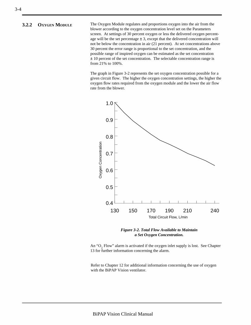
The Oxygen Module regulates and proportions oxygen into the air from theblower according to the oxygen concentration level set on the Parametersscreen. At settings of 30 percent oxygen or less the delivered oxygen percent-age will be the set percentage ± 3, except that the delivered concentration willnot be below the concentration in air (21 percent). At set concentrations above30 percent the error range is proportional to the set concentration, and thepossible range of inspired oxygen can be estimated as the set concentration± 10 percent of the set concentration. The selectable concentration range isfrom 21% to 100%.
The graph in Figure 3-2 represents the set oxygen concentration possible for agiven circuit flow. The higher the oxygen concentration settings, the higher theoxygen flow rates required from the oxygen module and the lower the air flowrate from the blower.
An “O2 Flow” alarm is activated if the oxygen inlet supply is lost. See Chapter13 for further information concerning the alarm.
0.4
0.5
0.6
0.7
0.8
0.9
1.0
240210190170150130Total Circuit Flow, L/min
Oxy
gen
Con
cent
ratio
n
Figure 3-2. Total Flow Available to Maintaina Set Oxygen Concentration.
3.2.2 OXYGEN MODULE
Refer to Chapter 12 for additional information concerning the use of oxygenwith the BiPAP Vision ventilator.

3-5
BiPAP Vision Clinical Manual
Figure 3-3 provides a representation of the method for generation, control anddelivery of therapy.
Ambient air is drawn through the air inlet filter and pressurized in the blowerassembly. System flow and pressure are then regulated at the blower outlet bythe Pressure Valve Assembly (PVA). There are two valves in the valveassembly that work in tandem to produce the desired pressure in the circuit.During the IPAP phase, flow from the blower is directed through the patientcircuit at the preset pressure. During expiration and transition to the EPAPphase, the PVA responds as necessary to allow excess flow to be exhaustedfrom the system to attain EPAP.
A pneumotach located in the Air Flow Module (AFM) is positioned after thePVA and immediately before the machine outlet. The AFM monitors total gasflow and machine pressure and transmits the data to the main controller system.
The proximal pressure is measured at the patient connection and compared tothe set pressure. The delivered pressure is thereby controlled and maintained atthe patient connection.
Blower
AFM(mass airflowsensor)
O2 InjectionPointTo PAS
Air F
ilter
AmbientAir
Exhaust
ToPatient
Proximal PressureLine
PVA
Figure 3-3. The BiPAP Vision Pneumatic System.
3.2.3 PNEUMATIC SYSTEM

3-6
BiPAP Vision Clinical Manual
3.2.4 STANDBY MODE The Standby mode, activated when the Standby key on the Monitoring screenis pressed, decreases the output flow to an idle state. This feature allows theclinician to place the ventilator in Standby while performing mask fittings,setting the prescription, etc. The Standby mode may be selected when nopatient is connected to the Vision ventilator.
When the Standby mode is activated, the graph display area is blanked andSTANDBY flashes in the middle of the screen. All measured parameters arezeroed.
In the Standby mode, all patient alarms are deactivated. Only the Vent Inop andCheckVent alarms are active. The following keys remain active:
• PARAMETERS• MODE• ALARMS• Options
If you make any changes to the system (e.g., parameters changes, alarmsettings, etc.), the changes are effective when you exit the Standby mode.
The Standby mode is manually deactivated by pressing the Standby key asecond time. As a safety feature, the Standby mode is automatically deactivatedif the Vision senses that a patient is connected to the circuit and is triggeringspontaneous breaths.

3-7
BiPAP Vision Clinical Manual
The accuracy and responsiveness of the system is maintained by continuousanalysis of the delivered flow. The flow measured at the Air Flow Module(AFM) is analyzed to derive a signal proportional to the Total Flow Rate (Vtot)in the patient circuit. This signal contains a component derived from the flowdelivered to the patient (Estimated Patient Flow Rate, [Vest]) as well as acomponent derived from circuit leaks (Estimated Leak Flow Rate, [Vleak]).Circuit leaks are comprised of intentional leak through the exhalation port aswell as any unintentional leaks that may be present in the circuit or at thepatient connection (Vleak = intentional + unintentional leaks).
Vtot = Vest + Vleak
Leak (Vleak)
Total Flow (Vtot)
PatientFlow (Vest)
(Intentional + Unintentional)
VisionUnit
Figure 3-4. Data Locations for Flow Analysis.
3.2.5 FLOW ANALYSIS
3-8
BiPAP Vision Clinical Manual
Leak tolerance is the unit’s ability to respond to changes in leaks. The BiPAPVision ventilator uses two primary mechanisms to identify and adjust to leaks.
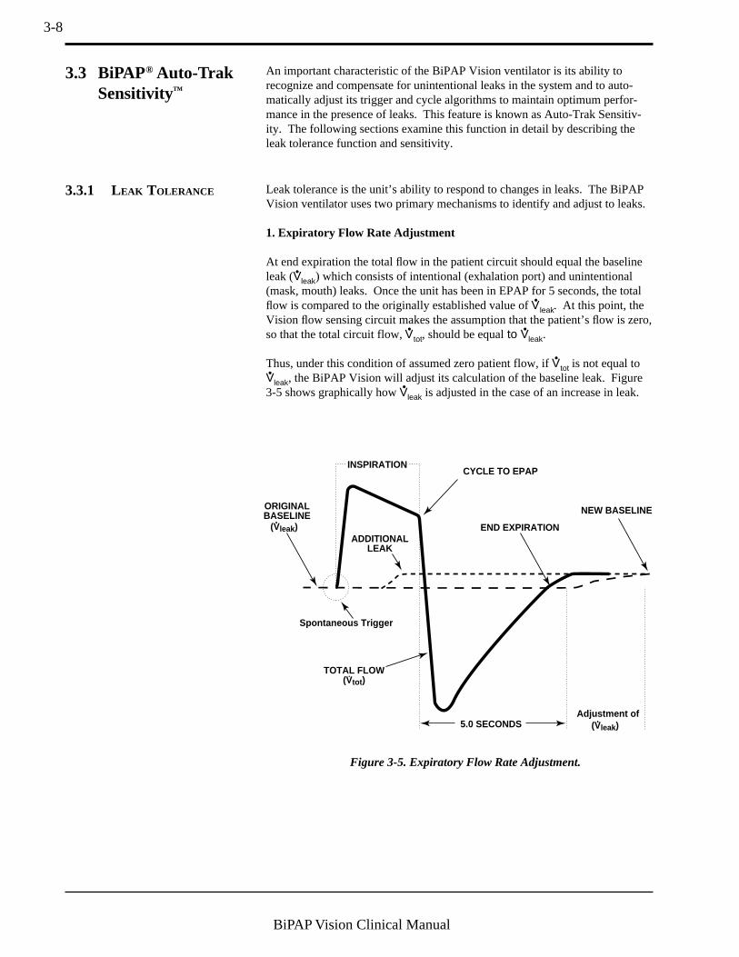
1. Expiratory Flow Rate Adjustment
At end expiration the total flow in the patient circuit should equal the baselineleak (Vleak) which consists of intentional (exhalation port) and unintentional(mask, mouth) leaks. Once the unit has been in EPAP for 5 seconds, the totalflow is compared to the originally established value of Vleak. At this point, theVision flow sensing circuit makes the assumption that the patient’s flow is zero,so that the total circuit flow, Vtot, should be equal to Vleak.
Thus, under this condition of assumed zero patient flow, if Vtot is not equal toVleak, the BiPAP Vision will adjust its calculation of the baseline leak. Figure3-5 shows graphically how Vleak is adjusted in the case of an increase in leak.
CYCLE TO EPAP
END EXPIRATIONADDITIONAL
LEAK
NEW BASELINEORIGINALBASELINE
INSPIRATION
5.0 SECONDSAdjustment of
Spontaneous Trigger
(Vleak)
(Vleak)
TOTAL FLOW(Vtot)
Figure 3-5. Expiratory Flow Rate Adjustment.
3.3.1 LEAK TOLERANCE
An important characteristic of the BiPAP Vision ventilator is its ability torecognize and compensate for unintentional leaks in the system and to auto-matically adjust its trigger and cycle algorithms to maintain optimum perfor-mance in the presence of leaks. This feature is known as Auto-Trak Sensitiv-ity. The following sections examine this function in detail by describing theleak tolerance function and sensitivity.
3.3 BiPAP® Auto-TrakSensitivity™
3-9
BiPAP Vision Clinical Manual
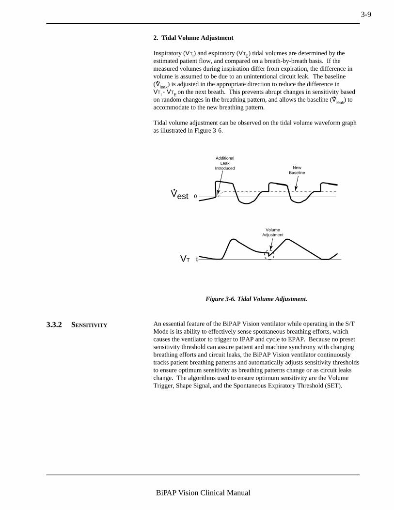
2. Tidal Volume Adjustment
Inspiratory (VTI) and expiratory (VTE) tidal volumes are determined by theestimated patient flow, and compared on a breath-by-breath basis. If themeasured volumes during inspiration differ from expiration, the difference involume is assumed to be due to an unintentional circuit leak. The baseline(Vleak) is adjusted in the appropriate direction to reduce the difference inVTI - VTE on the next breath. This prevents abrupt changes in sensitivity basedon random changes in the breathing pattern, and allows the baseline (Vleak) toaccommodate to the new breathing pattern.
Tidal volume adjustment can be observed on the tidal volume waveform graphas illustrated in Figure 3-6.
An essential feature of the BiPAP Vision ventilator while operating in the S/TMode is its ability to effectively sense spontaneous breathing efforts, whichcauses the ventilator to trigger to IPAP and cycle to EPAP. Because no presetsensitivity threshold can assure patient and machine synchrony with changingbreathing efforts and circuit leaks, the BiPAP Vision ventilator continuouslytracks patient breathing patterns and automatically adjusts sensitivity thresholdsto ensure optimum sensitivity as breathing patterns change or as circuit leakschange. The algorithms used to ensure optimum sensitivity are the VolumeTrigger, Shape Signal, and the Spontaneous Expiratory Threshold (SET).
Vest
VT
0
0
AdditionalLeak
Introduced NewBaseline
VolumeAdjustment
Figure 3-6. Tidal Volume Adjustment.
3.3.2 SENSITIVITY
3-10
BiPAP Vision Clinical Manual
The volume trigger is one method used to trigger IPAP during spontaneousbreathing in the S/T Mode. The volume trigger threshold is 6 cc of accumu-lated volume above the baseline leak (Vleak). When patient effort generatesinspiratory flow causing 6 cc of volume to accumulate above baseline (Vleak),IPAP is triggered:
Volume trigger threshold = 6 cc volume above Vleak baseline
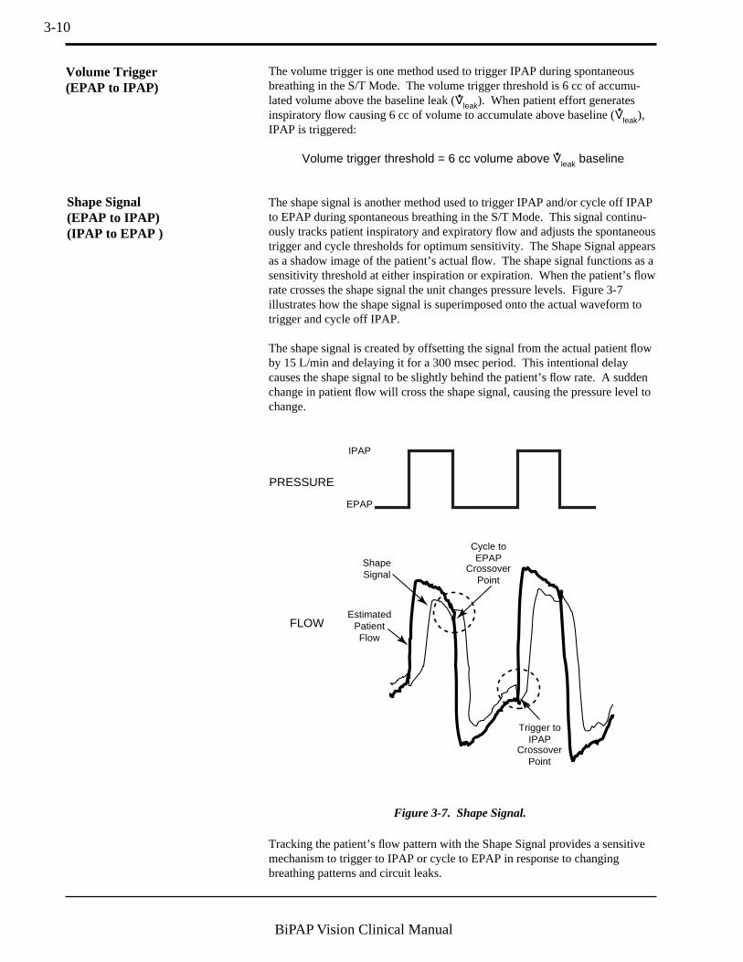
The shape signal is another method used to trigger IPAP and/or cycle off IPAPto EPAP during spontaneous breathing in the S/T Mode. This signal continu-ously tracks patient inspiratory and expiratory flow and adjusts the spontaneoustrigger and cycle thresholds for optimum sensitivity. The Shape Signal appearsas a shadow image of the patient’s actual flow. The shape signal functions as asensitivity threshold at either inspiration or expiration. When the patient’s flowrate crosses the shape signal the unit changes pressure levels. Figure 3-7illustrates how the shape signal is superimposed onto the actual waveform totrigger and cycle off IPAP.
The shape signal is created by offsetting the signal from the actual patient flowby 15 L/min and delaying it for a 300 msec period. This intentional delaycauses the shape signal to be slightly behind the patient’s flow rate. A suddenchange in patient flow will cross the shape signal, causing the pressure level tochange.
Tracking the patient’s flow pattern with the Shape Signal provides a sensitivemechanism to trigger to IPAP or cycle to EPAP in response to changingbreathing patterns and circuit leaks.
ShapeSignal
IPAP
EPAP
CrossoverPoint
Cycle toEPAP
CrossoverPoint
Trigger toIPAP
EstimatedPatientFlow
PRESSURE
FLOW
Figure 3-7. Shape Signal.
Shape Signal(EPAP to IPAP)(IPAP to EPAP )
Volume Trigger(EPAP to IPAP)

3-11
BiPAP Vision Clinical Manual
A second method used to cycle off IPAP during spontaneous breathing in theS/T Mode is called Spontaneous Expiratory Threshold (SET). The SET is anelectronic signal that rises in proportion to the inspiratory flow rate on eachbreath. When the Spontaneous Expiratory Threshold (SET) and actual patientflow value are equal, the unit cycles to EPAP.
A maximum IPAP time of 3.0 seconds acts as a safety mechanism to limit thetime spent at the IPAP level during spontaneous breathing in the S/T Mode.Once the time limit is reached, the unit automatically cycles off IPAP to theEPAP level.
As flow begins to decrease during IPAP, a flow reversal can occur due to alarge leak around the mask or because the patient’s mouth is open. When theVision unit senses this flow reversal, the unit automatically cycles to the EPAPlevel.
The sensitivity criteria for spontaneous breathing in the S/T mode can besummarized as follows:
Spontaneous Trigger to IPAP
A transition from EPAP to IPAP will occur when one of the following condi-tions is met:• Patient flow exceeds the shape signal• 6 cc inspired volume accumulates above baseline flow (Vleak)
Cycle to EPAP
The transition from IPAP to EPAP will occur when one of the followingconditions is met:• Patient flow is less than the shape signal• Spontaneous Expiratory Threshold (SET) is achieved• A 3.0 second maximum IPAP time has occurred (safety feature)• Flow reversal occurs during IPAP (safety feature)
SpontaneousExpiratoryThreshold
PRESSURE
FLOW
EPAP
IPAP
Figure 3-8. Spontaneous Expiratory Threshold.
Spontaneous ExpiratoryThreshold(IPAP to EPAP)
Maximum IPAP Time(IPAP to EPAP)
Summary
Flow Reversal(IPAP to EPAP)
3-12
BiPAP Vision Clinical Manual
The ventilator incorporates self-diagnostic testing capabilities and a number ofsafety features. System internal functions are checked automatically at start- upand periodically throughout operation. The microprocessors continuouslyobtain readings from internal sensors to monitor machine functions andoperating conditions. Device malfunctions or abnormal operating conditionsare analyzed and reported according to the level of severity. Two primaryalarm functions, Check Ventilator and Ventilator Inoperative, are available toidentify a system malfunction.
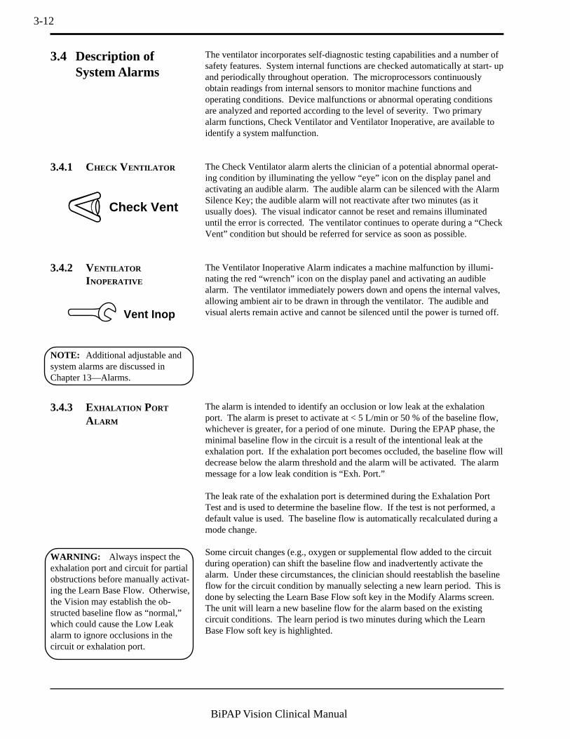
The Check Ventilator alarm alerts the clinician of a potential abnormal operat-ing condition by illuminating the yellow “eye” icon on the display panel andactivating an audible alarm. The audible alarm can be silenced with the AlarmSilence Key; the audible alarm will not reactivate after two minutes (as itusually does). The visual indicator cannot be reset and remains illuminateduntil the error is corrected. The ventilator continues to operate during a “CheckVent” condition but should be referred for service as soon as possible.
The Ventilator Inoperative Alarm indicates a machine malfunction by illumi-nating the red “wrench” icon on the display panel and activating an audiblealarm. The ventilator immediately powers down and opens the internal valves,allowing ambient air to be drawn in through the ventilator. The audible andvisual alerts remain active and cannot be silenced until the power is turned off.
3.4 Description ofSystem Alarms
3.4.1 CHECK VENTILATOR
3.4.2 VENTILATOR
I NOPERATIVE
Check Vent
Vent Inop
NOTE: Additional adjustable andsystem alarms are discussed inChapter 13—Alarms.
3.4.3 EXHALATION PORT
ALARM
The alarm is intended to identify an occlusion or low leak at the exhalationport. The alarm is preset to activate at < 5 L/min or 50 % of the baseline flow,whichever is greater, for a period of one minute. During the EPAP phase, theminimal baseline flow in the circuit is a result of the intentional leak at theexhalation port. If the exhalation port becomes occluded, the baseline flow willdecrease below the alarm threshold and the alarm will be activated. The alarmmessage for a low leak condition is “Exh. Port.”
The leak rate of the exhalation port is determined during the Exhalation PortTest and is used to determine the baseline flow. If the test is not performed, adefault value is used. The baseline flow is automatically recalculated during amode change.
Some circuit changes (e.g., oxygen or supplemental flow added to the circuitduring operation) can shift the baseline flow and inadvertently activate thealarm. Under these circumstances, the clinician should reestablish the baselineflow for the circuit condition by manually selecting a new learn period. This isdone by selecting the Learn Base Flow soft key in the Modify Alarms screen.The unit will learn a new baseline flow for the alarm based on the existingcircuit conditions. The learn period is two minutes during which the LearnBase Flow soft key is highlighted.
WARNING: Always inspect theexhalation port and circuit for partialobstructions before manually activat-ing the Learn Base Flow. Otherwise,the Vision may establish the ob-structed baseline flow as “normal,”which could cause the Low Leakalarm to ignore occlusions in thecircuit or exhalation port.
3-13
BiPAP Vision Clinical Manual
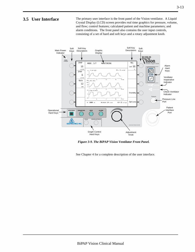
The primary user interface is the front panel of the Vision ventilator. A LiquidCrystal Display (LCD) screen provides real time graphics for pressure, volume,and flow; control features; calculated patient and machine parameters; andalarm conditions. The front panel also contains the user input controls,consisting of a set of hard and soft keys and a rotary adjustment knob.
3.5 User Interface
Figure 3-9. The BiPAP Vision Ventilator Front Panel.
Graph ControlHard Keys
OperationalHard Keys
AlarmHardKeys
Soft KeyDescriptors
Soft KeyDescriptors
SoftKeysMain Power
Indicator
AdjustmentKnob
Pressure LinePort
PatientInterface
Port
GraphicDisplay
Ventilator Inoperative Indicator
Check Ventilator Indicator
SoftKeys
MODE: S/T MONITORINGIPAP
15
cm H2O
cm H2O
EPAP
6
Rate
Options
Standby
12
BPM
%O2
55
%
VT 1000 ml PIP 15 cm H2OMinVent 14 L/min
PS = 9 cm H2OP (cm H2O)
Vol (ml)
Flow (L/min)
set
See Chapter 4 for a complete description of the user interface.

3-14
BiPAP Vision Clinical Manual
When the Start/Stop switch is turned to START and the system completes aself test, the system Start-up screen is displayed. The Start-up screen allowsthe user to perform the Exhalation Port Test. The Exhalation Port Test charac-terizes the patient circuit by analyzing the leak rate of the exhalation port.During the test, the system learns the intentional exhalation port leak over thecomplete pressure range. The learned leak value is then stored in systemmemory and is used to perform leak calculations and provide an accuratedisplay of patient leak and tidal volume in the Data Display Area. When a testis performed successfully, the Data Display shows the unintentional leak (thedisplay will appear as “Pt. Leak” in the Data Display Area). If the test is notperformed or cannot be completed successfully, the system is unable toaccurately know the intentional leak and will display the total leak value(intentional + unintentional). The display will appear as “Tot. Leak” in theData Display Area.
3.6 Exhalation Port Test
NOTE: Perform the Exhalation Port Test at system power up and when exhalation ports are changed. See Section 6.2,Starting the Vision System.
NOTE: The Exhalation Port Test must be performed when using the Plateau Exhalation Valve (PEV), because the leakrate of the PEV is significantly different than the Disposable Exhalation Port or the Whisper Swivel.
WARNING: Failure to perform the Exhalation Port Test prior to initializing therapy may result in inaccurate estimatedtidal volume and minute ventilation readings. Subsequently, inaccurate minute ventilation readingscould alter the accuracy of the low minute ventilation alarm when set below 3 L/min.

4-1
BiPAP Vision Clinical Manual
Figure 4-1
This chapter describes the front panel controls, displays, and interface connec-tions, the rear panel connections and controls, and the available Vision options.
4.1 Overview Figure 4-1 illustrates the Vision front panel. The front panel includes:
• a set of control keys• a rotary adjustment knob• a graphic display panel• a patient interface port• a pressure line port
The Vision unit has eight hard keys and ten soft keys to control the ventilator,graphics, and alarms.
A hard key performs a single function regardless of the screen or display. Thehard keys are:
Chapter 4: Controls and Displays
Graph ControlHard Keys
OperationalHard Keys
AlarmHardKeys
Soft KeyDescriptors
Soft KeyDescriptors
SoftKeysMain Power
Indicator
AdjustmentKnob
Proximal Pressure Line Port
PatientInterface
Port
GraphicDisplay
Ventilator Inoperative Indicator
Check Ventilator Indicator
SoftKeys
MODE: S/T MONITORINGIPAP
15
cm H2O
cm H2O
EPAP
6
Rate
Options
Standby
12
BPM
%O2
55
%
VT 1000 ml PIP 15 cm H2OMinVent 14 L/min
PS = 9 cm H2OP (cm H2O)
Vol (ml)
Flow (L/min)
set
• MONITORING• PARAMETERS• MODE• ALARMS
• SCALE• FREEZE/UNFREEZE• ALARM SILENCE• ALARM RESET
The function of a soft key changes with the displayed screen. The soft keyfunction is displayed in its adjacent soft key descriptor.

4-2
BiPAP Vision Clinical Manual
4.2 Patient Circuit Connections
Pressure Line Port
The Pressure Line Port accepts the 1/8" ID Proximal Pressure Line from thepatient circuit to monitor patient pressure.
Patient Interface Port
The Patient Interface Port accepts a 22 mm ID bacteria filter.
The adjustment knob is a rotary knob that changes the value of a parameter thatis selected with a soft key. It is active only when a soft key selection has beenmade.
To increase the value of a selected parameter, turn the knob clockwise; todecrease the value of a selected parameter, turn the knob counterclockwise.The knob has detents, each of which corresponds to one increment of theparameter value. The increment is equal to the resolution of the parameter.
For example, when the IPAP parameter is selected, each detent will change thevalue of the parameter by 1 cm H2O.
4.3 Adjustment Knob

4-3
BiPAP Vision Clinical Manual
4.4.2 SOFT KEY
DESCRIPTORS
When a soft key is active, the adjacent descriptor is highlighted and displaysdata pertinent to the soft key.
When modifying or setting parameters, the descriptor displays the set value andthe parameter units. The CPAP, IPAP, EPAP, and Rate descriptors also displaythe measured value in a smaller size below the set value when the parameter isselected.EPAP
15
cm H2O
set
15
ParameterSet Value
MeasuredValue
ParameterUnits
4.4 Soft Keys
4.4.1 SOFT KEY OPERATION The BiPAP Vision ventilator has 10 soft keys aligned vertically along the sidesof the LCD screen (5 keys on each side). The functions of the soft keys varywith the screen displayed. Soft keys are used to select parameters for adjust-ment, to display screens, or to provide information. When a soft key is pressed,the adjacent descriptor is highlighted in reverse video indicating the parameterlocated in the descriptor box is active and can be modified by using the adjust-ment knob. A second press of the same soft key deselects the descriptor box.If a descriptor area is blank, the soft key adjacent to it is inactive. The soft keycontrols are described in each pertinent section.
NOTE: If there is no user activity forthree minutes, the displayreturns to the Monitoringscreen.

4-4
BiPAP Vision Clinical Manual
4.5 Hard Keys—Operational
The hard keys are:
• MONITORING• PARAMETERS
MONITORING
4.5.1 MONITORING HARD KEY
BPM
VT 1000 ml MinVent 4 L/min
OperationalHard Keys
Flow (L/min)
In addition to the soft keys, the Vision ventilator user interface consists of fourmain screens, each displayed by one of the four Operational Hard Keys.
Purpose: Display the Monitoring screen for the active mode. Allows theoperator to return to the Monitoring screen from any screen. Noparameter, alarm, or mode changes can be made while theMonitoring screen is displayed.
Active: At all times
Note: If there is no user activity (e.g., pressing any keys) for threeminutes while displaying any other screen, the system automati-cally returns to the Monitoring screen.
• MODE• ALARMS
MODE: S/T MONITORINGIPAP
15
cm H2O
cm H2O
EPAP
6
Rate
Options
12
BPM
%O2
55
%
VT 1000 ml PIP 15 cm H2OMinVent 14 L/min
PS = 9 cm H2OP (cm H
2O)
Vol (ml)
Flow (L/min)
set
The Monitoring screen can be considered the “home”screen of the display. It displays the current operatingmode, contains graphic displays of pressure, tidal volume,and flow, and includes numerical data displays for calcu-lated and measured parameters. When using the optionaloxygen module, the screen also displays the set oxygenconcentration.

4-5
BiPAP Vision Clinical Manual
4.5.3 MODE HARD KEY
MODE
4.5.4 ALARMS HARD KEY
ALARMS
4.5.2 PARAMETERS HARD KEY
PARAMETERS Purpose: Display the Modify Parameters screen for the active mode. TheModify Parameters screen allows the operator to change aparameter for the active mode.
Active: At all times
Purpose: Display the Change Mode screen. Real time graphic and numericdisplays for the current mode provide for continuous monitoringof the patient and ventilator while making changes.
Active: At all times
Purpose: Display the Modify Alarms screen.
Active: At all times
CHANGE MODE
CPAP
OPERATING IN: S/TP (cm H2O)
Vol (ml)
Flow (L/min)
The Change Mode screen allows the operator to reviewand select a new operating mode. Selecting a new modefrom the Change Mode screen will initiate the changemode sequence and permit the user to adjust the parametersfor the new mode before activating the mode.
P (cm H2O)
Vol (ml)
Flow (L/min)
MODE: S/T MODIFY
PARAMETERS
IPAP
cm H2O
%O2
IPAP
Rise Time
%
15
15
set
EPAP
cm H2O
6
6
set
Rate
PS = 9 cm H2O
BPM
12
12
set
0.1set
Timed Insp
sec
sec
3.0set
55set
VT 700 ml PIP 8 cm H2OMinVent 14 L/min
Ti/Ttot 15 % Pt. Leak 1 L/min Pt. Trig 5 %
The Modify Parameters screen allow the operator to reviewand adjust the parameters for the current operational mode.It displays the current operating mode, contains graphicdisplays of pressures, tidal volume, and flow, and includesnumerical displays for calculated and measured param-eters.
MODE: S/T MODIFY
ALARMS
Hi P
30
13
cm H2O
VT 700 ml PIP 8 cm H2OMinVent 14 L/min
Ti/Ttot 15 % Pt. Trig 5 %Pt. Leak 1 L/min
Lo P
cm H2O
set
set
Lo P Delay
Learn
Base
Flow
16
sec
set
Apnea
Help
Disabled
sec
set
Lo MinVent
20set
Hi Rate
80
BPM
set
Lo Rate
5
BPM
set
L/minP (cm H2O)
Vol (ml)
Flow (L/min)
The Modify Alarms screen allows the operator to reviewand change the alarm limits for the active mode. Whileviewing the Modify Alarms screen, real-time graphic andcalculated numeric displays for the active mode provide forcontinuous monitoring of the patient and ventilator.

4-6
BiPAP Vision Clinical Manual
The Graph Control Hard Keys are:
• SCALE• FREEZE/UNFREEZE
4.6 Hard Keys—Graph Control
4.6.1 SCALE HARD KEY
4.6.2 FREEZE/UNFREEZE
HARD KEY
Graph ControlHard Keys
Purpose: Display the Modify Scale screen. The Modify Scale screenallows the operator to change the graph scales.
Active: At all times, except in the Change Mode screen.
Purpose: Freeze the graph displays if the displays are scrolling when thekey is pressed. Conversely, it unfreezes the display if the displaysare frozen when the key is pressed.
Active: At all times except in the Change Mode screen.
Note: Real-time pressure, flow, and volume data are not plotted whenthe graphs are frozen. When the Freeze Key is active the message“Freeze Active” is displayed in the Mode/Message Area.
4-7
BiPAP Vision Clinical Manual
4.7 Hard Keys—Alarm
4.7.1 ALARM SILENCE HARD
KEY
4.7.2 ALARM RESET HARD
KEY
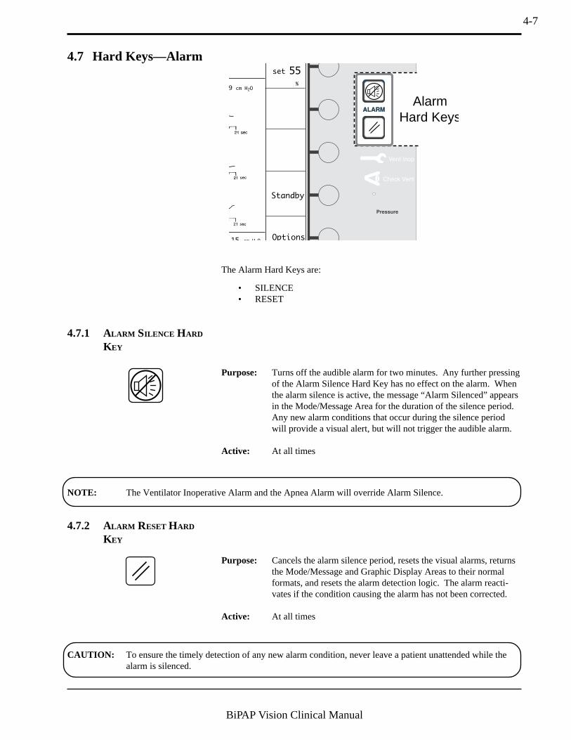
The Alarm Hard Keys are:
• SILENCE• RESET
Options
Standby
55
%
15 cm H O
9 cm H2O
set
AlarmHard Keys
CAUTION: To ensure the timely detection of any new alarm condition, never leave a patient unattended while thealarm is silenced.
Purpose: Turns off the audible alarm for two minutes. Any further pressingof the Alarm Silence Hard Key has no effect on the alarm. Whenthe alarm silence is active, the message “Alarm Silenced” appearsin the Mode/Message Area for the duration of the silence period.Any new alarm conditions that occur during the silence periodwill provide a visual alert, but will not trigger the audible alarm.
Active: At all times
Purpose: Cancels the alarm silence period, resets the visual alarms, returnsthe Mode/Message and Graphic Display Areas to their normalformats, and resets the alarm detection logic. The alarm reacti-vates if the condition causing the alarm has not been corrected.
Active: At all times
NOTE: The Ventilator Inoperative Alarm and the Apnea Alarm will override Alarm Silence.

4-8
BiPAP Vision Clinical Manual
4.8 Ventilator Warning Indicators
4.8.1 VENTILATOR
I NOPERATIVE INDICATOR
Vent Inop
4.8.2 CHECK VENTILATOR
I NDICATOR
Check Vent
Purpose: Alerts of a machine malfunction by illuminating the red “wrench”icon on the display panel and activating an audible alarm. Theventilator immediately powers down and opens the internal valvesallowing ambient air to be drawn through the ventilator byspontaneous breathing.
The audible and visual alerts remain active and cannot be silenceduntil the Start/Stop switch is placed in the Stop position.
Purpose: Alerts of a potential abnormal operating condition by illuminatingthe yellow “eye” icon on the display panel and activating anaudible alarm. The audible alarm can be temporarily silencedwith the Alarm Silence Key. However, the visual indicatorcannot be reset and remains illuminated until the error is cor-rected. The unit should be referred for service.
4-9
BiPAP Vision Clinical Manual
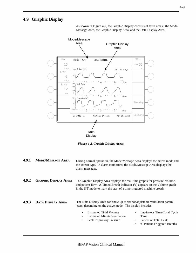
4.9 Graphic DisplayAs shown in Figure 4-2, the Graphic Display consists of three areas: the Mode/Message Area, the Graphic Display Area, and the Data Display Area.
4.9.1 MODE/MESSAGE AREA During normal operation, the Mode/Message Area displays the active mode andthe screen type. In alarm conditions, the Mode/Message Area displays thealarm messages.
4.9.2 GRAPHIC DISPLAY AREA The Graphic Display Area displays the real-time graphs for pressure, volume,and patient flow. A Timed Breath Indicator (V) appears on the Volume graphin the S/T mode to mark the start of a time-triggered machine breath.
Figure 4-2. Graphic Display Areas.
MODE: S/T MONITORINGIPAP
15
cm H2O
cm H2O
EPAP
6
Rate
Options
Standby
12
BPM
%O2
55
%
VT 1000 ml PIP 15 cm H2OMinVent 14 L/min
PS = 9 cm H2O
Mode/MessageArea Graphic Display
Area
DataDisplay
P (cm H2O)
Vol (ml)
Flow (L/min)
set
4.9.3 DATA DISPLAY AREA The Data Display Area can show up to six nonadjustable ventilation param-eters, depending on the active mode. The display includes:
• Estimated Tidal Volume• Estimated Minute Ventilation• Peak Inspiratory Pressure
• Inspiratory Time/Total CycleTime
• Patient or Total Leak• % Patient Triggered Breaths
4-10
BiPAP Vision Clinical Manual
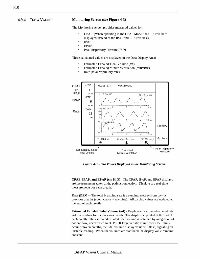
Monitoring Screen (see Figure 4-3)
The Monitoring screen provides measured values for:
• CPAP (When operating in the CPAP Mode, the CPAP value isdisplayed instead of the IPAP and EPAP values.)
• IPAP• EPAP• Peak Inspiratory Pressure (PIP)
Three calculated values are displayed in the Data Display Area:
• Estimated Exhaled Tidal Volume (VT)• Estimated Exhaled Minute Ventilation (MinVent)• Rate (total respiratory rate)
MODE: S/T MONITORINGIPAP
15
cm H2O
cm H2O
EPAP
6
Rate
Options
Standby
12
BPM
VT 1000 ml PIP 15 cm H2OMinVent 14 L/min
PS = 9 cm H2O
CPAPor
IPAP
EPAP
Rate
Estimated ExhaledTidal Volume
EstimatedMinute Ventilation
Peak InspiratoryPressure
P (cm H2O)
Vol (ml)
Flow (L/min)
4.9.4 DATA VALUES
Figure 4-3. Data Values Displayed in the Monitoring Screen.
CPAP, IPAP, and EPAP (cm H2O) - The CPAP, IPAP, and EPAP displays
are measurements taken at the patient connection. Displays are real-timemeasurements for each breath.
Rate (BPM) - The total breathing rate is a running average from the sixprevious breaths (spontaneous + machine). All display values are updated atthe end of each breath.
Estimated Exhaled Tidal Volume (ml) - Displays an estimated exhaled tidalvolume reading for the previous breath. The display is updated at the end ofeach breath. The estimated exhaled tidal volume is obtained by integration ofpatient flow, uncorrected to BTPS. If large variations in flow (>15 L/min)occur between breaths, the tidal volume display value will flash, signaling anunstable reading. When the volumes are stabilized the display value remainsconstant.

4-11
BiPAP Vision Clinical Manual
Estimated Exhaled Minute Ventilation (L/min) - Displays the estimatedexhaled minute ventilation based on a running average of the previous sixbreaths. The display is updated at the end of each breath.
Peak Inspiratory Pressure (cm H2O) - Displays the peak pressure levelobtained during the breath. The measurement is proximal to the patientconnection. The display is updated at the end of each inspiration.
Parameters Screen (see Figure 4-4)
Additional calculated values are displayed in the Data Display Area when theParameters screen is active for the CPAP or S/T Mode.
Leak (L/min) - Displays either the Patient Leak or Total Leak.
Patient Leak - When the exhalation port test is successfullyperformed, the ventilator learns the intentional leak rate at theexhalation port and subtracts this value from the total leak.Therefore, the remaining leaks are a result of unintentionalleaks typically found at the patient connection. The patientleak is the average leak value calculated over the entirebreathing cycle. The display value is updated after eachbreath.
Total Leak - If the exhalation port test is not performed, thetotal (intentional + unintentional) leak is displayed. Total leakis the average leak value calculated during the entire breathingcycle. The display value is updated after each breath.
Vol (ml)
P (cm H2O)
Flow (L/min)
MODE: S/T MODIFY
PARAMETERS
IPAP
cm H2O
%O2
IPAP
Rise Time
%
15
15
set
EPAP
cm H2O
6
6
set
Rate
PS = 9 cm H2O
BPM
12
12
set
0.2set
Timed Insp
sec
sec
3.0set
55set
VT 700 ml PIP 8 cm H2OMinVent 14 L/min
Ti/Ttot 15 % Pt. Leak 10 L/min Pt. Trig 5 %
Inspiratory Time/Total Cycle Time
Patient LeakPercentage of
Patient-TriggeredBreaths
Figure 4-4. Data Values Displayed in the Parameters Screen.
4-12
BiPAP Vision Clinical Manual
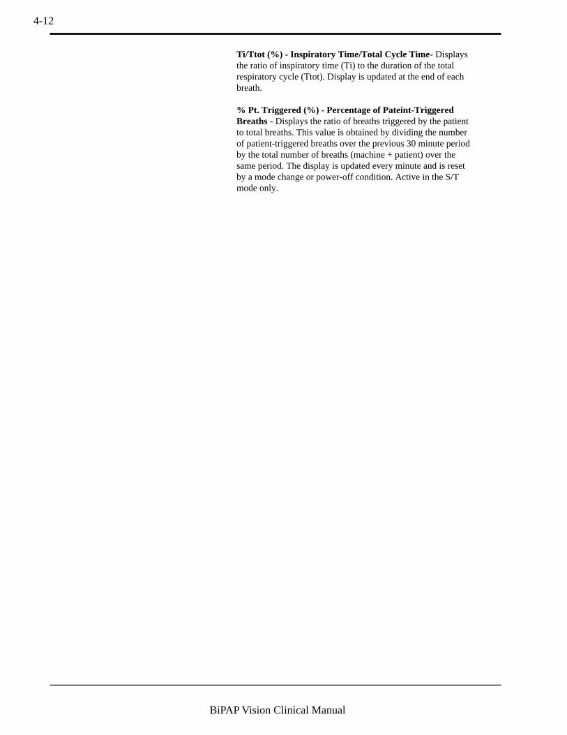
Ti/Ttot (%) - Inspiratory Time/Total Cycle Time - Displaysthe ratio of inspiratory time (Ti) to the duration of the totalrespiratory cycle (Ttot). Display is updated at the end of eachbreath.
% Pt. Triggered (%) - Percentage of Pateint-TriggeredBreaths - Displays the ratio of breaths triggered by the patientto total breaths. This value is obtained by dividing the numberof patient-triggered breaths over the previous 30 minute periodby the total number of breaths (machine + patient) over thesame period. The display is updated every minute and is resetby a mode change or power-off condition. Active in the S/Tmode only.

4-13
BiPAP Vision Clinical Manual
4.10 Rear Panel Figure 4-5 shows the rear panel of the Vision unit. The rear panel includes:
• Power entry module• Inlet filter and cover (see section 15.3)• Oxygen Module (see chapter 14)• Start/Stop switch• Power cord retainer
580123
Oxygen Inlet Pressure Range: 50 to 100 psig
580NEW
100 - 240 V - T6.3 A, 250 V, 5 x 20 mm
100 - 240 V , 50/60 Hz
CLASS ITYPE BF
3.0 A Max.
WARNING: Disconnect power supply before servicing.
WARNING: For continued protection against risk of fire, replace with same type and rating of fuse.
WARNING: Equipment not suitable for use in the presence of flammable anaesthetic mixture.
WARNING: Proper grounding is essential for safety.
CAUTION: Federal law restricts this device to sale by or on the order of a physician.CAUTION: Do not immerse the device.
Warnings & Cautions
NRTL/C
¤ VD E
0123
Figure 4-5. BiPAP Vision Rear Panel.
4.10.1 POWER ENTRY MODULE
The AC Inlet accepts a standard hospital-grade grounded power cord.
The module contains two fuses, placed in individual fuse drawers. The factory-set inlet voltage is set to the proper voltage for the country of operation.Chapter 14 describes how the fuses are inserted. See Chapter 16 for the properfuse size and rating.
4.10.2 START /STOP SWITCH
The Start/Stop switch is a push-button type switch, with “START” at the inposition. The Start switch begins operation, but power is always applied to theVision unit when the power cord is plugged into an operational wall outlet.
115V
Voltage Settingis Visible in Window
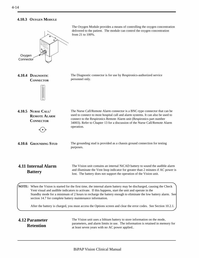
4-14
BiPAP Vision Clinical Manual
The Oxygen Module provides a means of controlling the oxygen concentrationdelivered to the patient. The module can control the oxygen concentrationfrom 21 to 100%.
4.10.3 OXYGEN MODULE
4.11 Internal AlarmBattery
4.12 ParameterRetention
The Vision unit contains an internal NiCAD battery to sound the audible alarmand illuminate the Vent Inop indicator for greater than 2 minutes if AC power islost. The battery does not support the operation of the Vision unit.
The Vision unit uses a lithium battery to store information on the mode,parameters, and alarm limits in use. The information is retained in memory forat least seven years with no AC power applied..
NOTE: When the Vision is started for the first time, the internal alarm battery may be discharged, causing the CheckVent visual and audible indicators to activate. If this happens, start the unit and operate in theStandby mode for a minimum of 2 hours to recharge the battery enough to eliminate the low battery alarm. Seesection 14.7 for complete battery maintenance information.
After the battery is charged, you must access the Options screen and clear the error codes. See Section 10.2.1.
¤
Serial #
Warnings & Cautions
!
CAUTION:Do not operate with cover removed.
WARNING: Disconnect supply before servicing.
Recommended Oxygen Pressure Range:
35 to 100 psigCAUTION:
When servicing, use only approved
replacement parts.
WARNING: Do not exceed maximum working
pressure.
OxygenConnector
4.10.4 DIAGNOSTIC
CONNECTOR
The Diagnostic connector is for use by Respironics-authorized servicepersonnel only.
4.10.5 NURSE CALL /REMOTE ALARM
CONNECTOR
The Nurse Call/Remote Alarm connector is a BNC-type connector that can beused to connect to most hospital call and alarm systems. It can also be used toconnect to the Respironics Remote Alarm unit (Respironics part number34003). Refer to Chapter 13 for a discussion of the Nurse Call/Remote Alarmoperation.
4.10.6 GROUNDING STUD The grounding stud is provided as a chassis ground connection for testingpurposes.

4-15
BiPAP Vision Clinical Manual
4.13 Options To display which, if any, of the options are installed on your machine, press theOPTIONS Soft Key on the Monitoring screen, then press the System Info SoftKey on the Options screen. The Mode/Message Area displays the softwareversion and which modules are installed. Chapter 10 details the operation anddisplay of the Options screen.

4-16
BiPAP Vision Clinical Manual
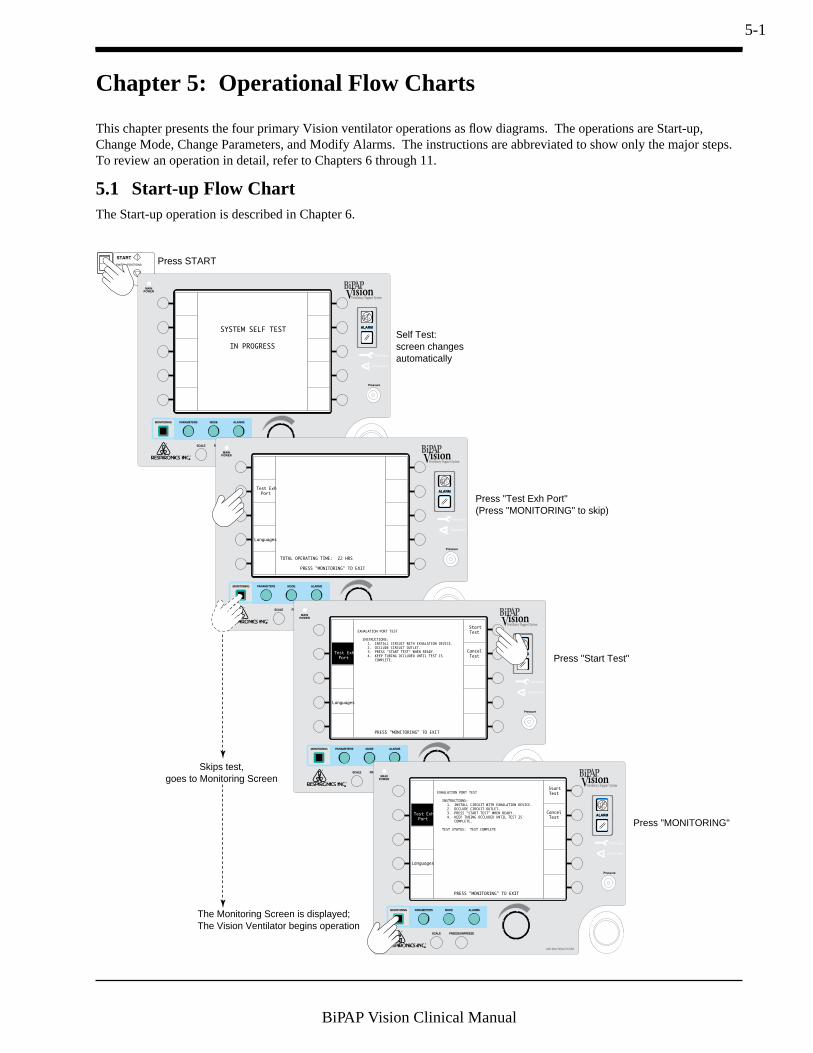
5-1
BiPAP Vision Clinical Manual
Chapter 5: Operational Flow Charts
This chapter presents the four primary Vision ventilator operations as flow diagrams. The operations are Start-up,Change Mode, Change Parameters, and Modify Alarms. The instructions are abbreviated to show only the major steps.To review an operation in detail, refer to Chapters 6 through 11.
SYSTEM SELF TEST
IN PROGRESS
Test Exh
Port
Languages
TOTAL OPERATING TIME: 22 HRS
PRESS "MONITORING" TO EXIT
Test Exh
Port
EXHALATION PORT TEST
INSTRUCTIONS:
1. INSTALL CIRCUIT WITH EXHALATION DEVICE.
2. OCCLUDE CIRCUIT OUTLET.
3. PRESS "START TEST" WHEN READY.
4. KEEP TUBING OCCLUDED UNTIL TEST IS
COMPLETE.
Start
Test
Cancel
Test
PRESS "MONITORING" TO EXIT
Test Exh
Port
EXHALATION PORT TEST
INSTRUCTIONS:
1. INSTALL CIRCUIT WITH EXHALATION DEVICE.
2. OCCLUDE CIRCUIT OUTLET.
3. PRESS "START TEST" WHEN READY.
4. KEEP TUBING OCCLUDED UNTIL TEST IS
COMPLETE.
TEST STATUS: TEST COMPLETE
Start
Test
Cancel
Test
PRESS "MONITORING" TO EXIT
Press START
Press "Test Exh Port"(Press "MONITORING" to skip)
Press "Start Test"
Press "MONITORING"
Self Test:screen changesautomatically
The Monitoring Screen is displayed;The Vision Ventilator begins operation
Skips test,goes to Monitoring Screen
Languages
Languages
5.1 Start-up Flow ChartThe Start-up operation is described in Chapter 6.
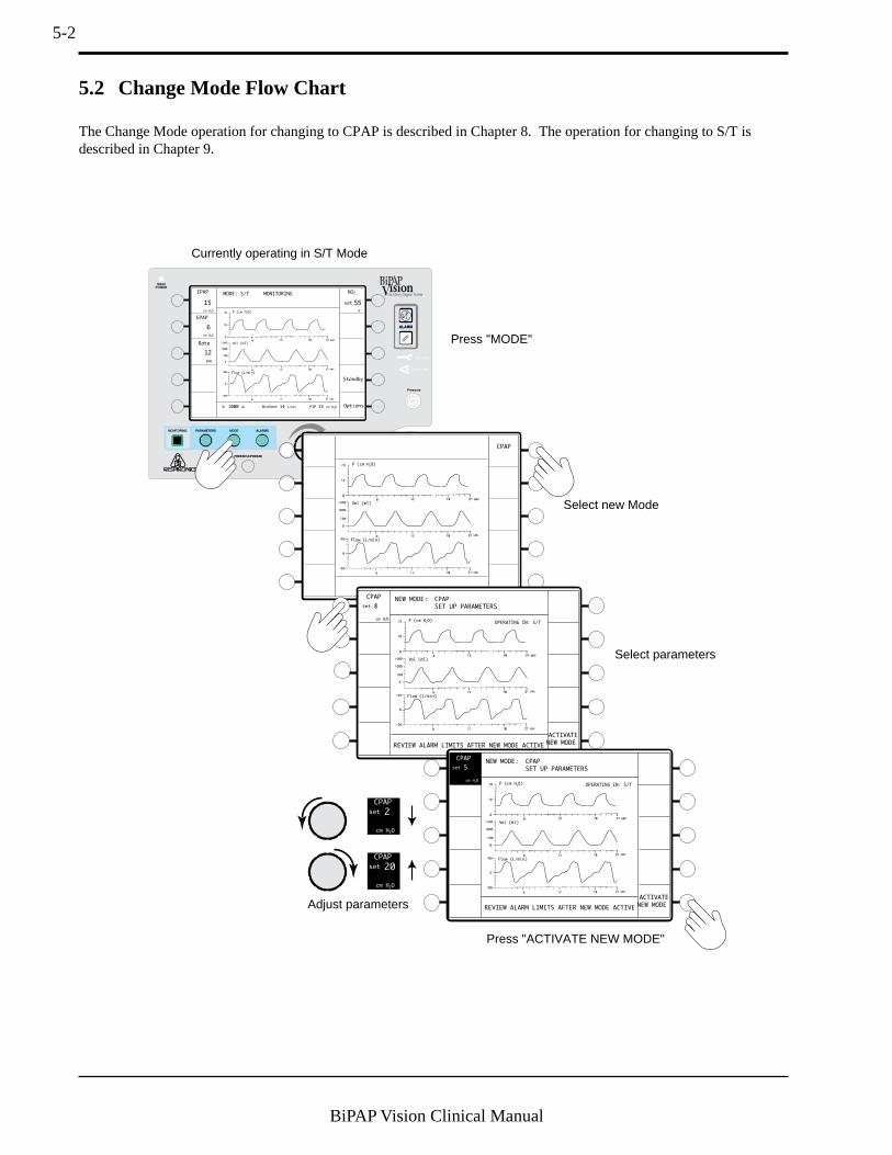
5-2
BiPAP Vision Clinical Manual
5.2 Change Mode Flow Chart
MODE: S/T MONITORINGIPAP
15
cm H2O
cm H2O
EPAP
6
Rate
Options
Standby
12
BPM
%O2
55
%
VT 1000 ml PIP 15 cm H2OMinVent 14 L/min
P (cm H2O)
Vol (ml)
Flow (L/min)
Press "MODE"
Select new Mode
Select parameters
Adjust parameters
Press "ACTIVATE NEW MODE"
CPAP
2
cm H2O
set
CPAP
20
cm H2O
set
CPAP
NEW MODE: CPAP
SET UP PARAMETERS
REVIEW ALARM LIMITS AFTER NEW MODE ACTIVE
CPAP
ACTIVATE
NEW MODE
cm H2O
8set
OPERATING IN: S/T
NEW MODE: CPAP
SET UP PARAMETERS
REVIEW ALARM LIMITS AFTER NEW MODE ACTIVE
ACTIVATE
NEW MODE
OPERATING IN: S/T
Currently operating in S/T Mode
P (cm H2O)
Vol (ml)
Flow (L/min)
P (cm H2O)
Vol (ml)
Flow (L/min)
P (cm H2O)
Vol (ml)
Flow (L/min)
CPAP
cm H2O
5set
set
The Change Mode operation for changing to CPAP is described in Chapter 8. The operation for changing to S/T isdescribed in Chapter 9.

5-3
BiPAP Vision Clinical Manual
5.3 Modify Parameters Flow Chart
Press "PARAMETERS"
Operating in S/T Mode, for example
Select parameter
Adjust parameter
EPAP
2
cm H2O
set
10
EPAP
20
cm H2O
set
10
MODE: S/T MONITORINGIPAP
15
cm H2O
cm H2O
EPAP
6
Rate
Options
Standby
12
BPM
%O2
55
%
VT 1000 ml PIP 15 cm H2OMinVent 14 L/min
PS = 9 cm H2O
MODE: S/T MODIFY
PARAMETERS
IPAP
cm H2O
%O2
IPAP
Rise Time
%
15
15
set
EPAP
cm H2O
6
6
set
Rate
PS = 9 cm H2O
BPM
12
12
set
0.1set
Timed Insp
sec
sec
3.0set
55set
VT 700 ml PIP 15 cm H2OMinVent 14 L/min
Ti/Ttot 15 % Pt. Leak 1 L/min Pt. Trig 5 %
Press "MONITORING"
MODE: S/T MODIFY
PARAMETERS
IPAP
cm H2O
%O2
IPAP
Rise Time
%
15
15
set
Rate
PS = 7 cm H2O
BPM
12
12
set
0.1set
Timed Insp
sec
sec
3.0set
55set
VT 700 ml PIP 15 cm H2OMinVent 14 L/min
Ti/Ttot 15 % Pt. Leak 1 L/min Pt. Trig 85 %
set
P (cm H2O)
Vol (ml)
Flow (L/min)
P (cm H2O)
Vol (ml)
Flow (L/min)
P (cm H2O)
Vol (ml)
Flow (L/min)
EPAP
cm H2O
8
10
set
The Modify Parameters operation for changing to CPAP is described in Chapter 8. The operation for modifying S/Tparameters is described in Chapter 9.

5-4
BiPAP Vision Clinical Manual
5.4 Modify Alarms Flow Chart
MODE: S/T MONITORINGIPAP
15
cm H2O
cm H2O
EPAP
6
Rate
Options
Standby
12
BPM
%O2
55
%
VT 1000 ml PIP 15 cm H2OMinVent 14 L/min
PS = 9 cm H2O
Select alarm to adjust
Press "ALARMS"
Adjust parameter
Press "MONITORING"
Hi Rate
4
BPM
set
Hi Rate
120set
BPM
Select Help for instructions if needed
MODE: S/T MODIFY
ALARMS
Hi P
30
10
cm H2O
VT 700 ml PIP 15 cm H2OMinVent 14 L/min
Ti/Ttot 15 % Pt. Trig 5 %Pt. Leak 1 L/min
Lo P
cm H2O
set
set
Lo P Delay
Learn
Base
Flow
16
sec
set
Apnea
Help
Disabled
sec
set
Lo MinVent
10set
Hi Rate
80
BPM
set
Lo Rate
5
BPM
set
L/min
Help
MODE: S/T MODIFY
ALARMS
Hi P
30
cm H2O
VT 700 ml PIP 15 cm H2OMinVent 14 L/min
Ti/Ttot 15 % Pt. Trig 85 %Pt. Leak 1 L/min
Lo P
cm H2O
set
Lo P Delay
Learn
Base
Flow
16
10
sec
set
Apnea
Disabled
sec
set
Lo MinVent
10set
L/min
Lo Rate
5set
BPM
Operating in S/T Mode, for example
Hi Rate
30set
BPM
Help
P (cm H2O)
Vol (ml)
Flow (L/min)
P (cm H2O)
Vol (ml)
Flow (L/min)
P (cm H2O)
Vol (ml)
Flow (L/min)
set
The Modify Alarms operation for changing to CPAP is described in Chapter 8. The operation for modifying S/T alarmsis described in Chapter 9.
The sample displays show the optional Alarm Module installed.
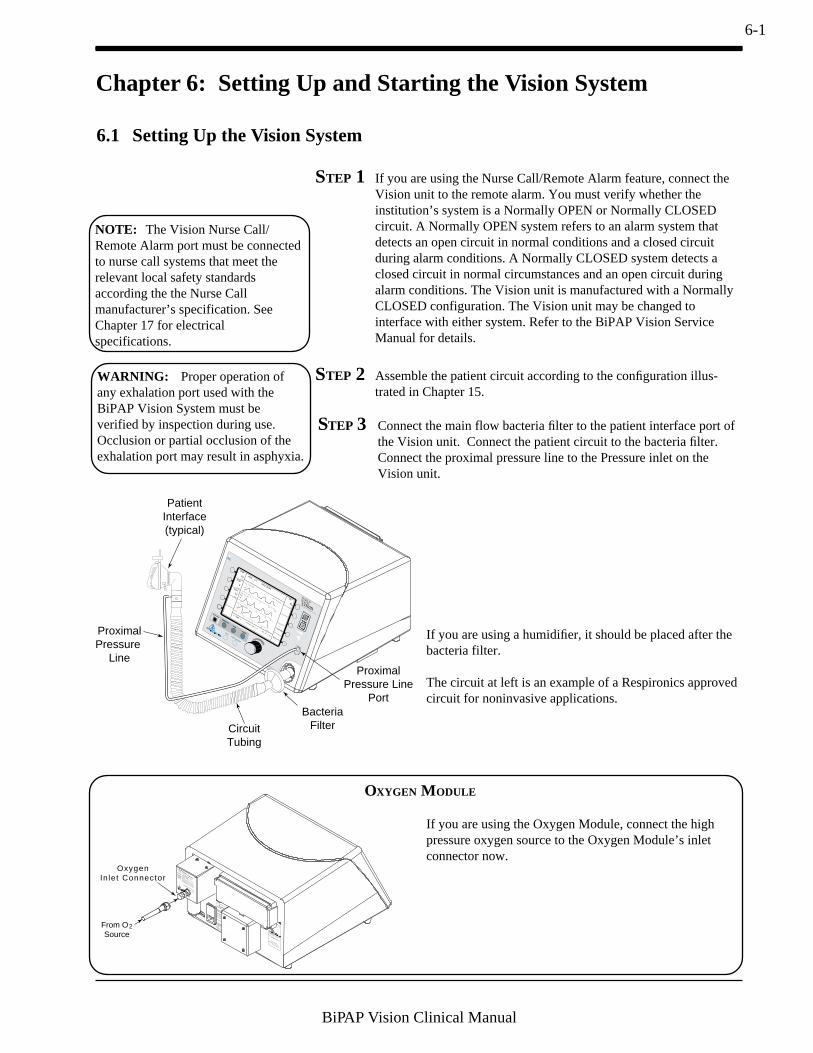
6-1
BiPAP Vision Clinical Manual
Chapter 6: Setting Up and Starting the Vision System
6.1 Setting Up the Vision System
STEP 3 Connect the main flow bacteria filter to the patient interface port ofthe Vision unit. Connect the patient circuit to the bacteria filter.Connect the proximal pressure line to the Pressure inlet on theVision unit.
If you are using a humidifier, it should be placed after thebacteria filter.
The circuit at left is an example of a Respironics approvedcircuit for noninvasive applications.
MODE: S/T MONITORING
IPAP
15
cm H2O
cm H2O
EPAP
6
Rate
Options
Standby
12
BPM
%O2
55
%
VT 1000
ml
PIP 15 cm H
2O
MinVent 14 L/min
PS = 9 cm H2O
P (cm H2O)
Vol (ml)
Flow (L/min)
CircuitTubing
BacteriaFilter
ProximalPressure Line
Port
ProximalPressure
Line
PatientInterface(typical)
STEP 2 Assemble the patient circuit according to the configuration illus-trated in Chapter 15.
115 VAC/60 Hz 230 VAC/50 Hz
Single Phase TBD
T Type
115 VAC - T 8 A - 1/4" x 1 1/4"
230 VAC - T 4 A - 5 x 20 mmTYPE BF
CLASS I
Warnings & Cautions
!
CAUTION:The voltage selection switch must be
set for the proper line voltage.
WARNING: For continued protection against risk
of fire, replace with the same type
and rating of fuse.
WARNING: Disconnect supply before servicing.
WARNING: DO NOT connect to an electrical
outlet controlled by a wall switch.
WARNING: This is an assist ventilator and is
intended to augment the ventilation
of a spontaneously breathing patient.
DANGER:Explosion Hazard. Do not use in the
presence of flammable anesthetics.IP22
CAUTION:U.S. federal law restricts the sale or
use of this device by or on the order
of a physician.
¤
Serial #
Warnings & Cautions
!
CAUTION:Do not operate with cover removed.
WARNING: Disconnect supply before servicing.
Recommended Oxygen Pressure Range:
35 to 100 psigCAUTION:
When servicing, use only approved
replacement parts.
WARNING: Do not exceed maximum working
pressure.
¤
¤
1 001 Mu r r y R i dge D r i v e
Murrysvi l le, Pennsylvania
15668 - 8550 U .S .A .
Serial #
Model # E123456D
When servicing, use only approved
replacement parts.
From O2Source
OxygenInlet Connector
OXYGEN MODULE
If you are using the Oxygen Module, connect the highpressure oxygen source to the Oxygen Module’s inletconnector now.
STEP 1 If you are using the Nurse Call/Remote Alarm feature, connect theVision unit to the remote alarm. You must verify whether theinstitution’s system is a Normally OPEN or Normally CLOSEDcircuit. A Normally OPEN system refers to an alarm system thatdetects an open circuit in normal conditions and a closed circuitduring alarm conditions. A Normally CLOSED system detects aclosed circuit in normal circumstances and an open circuit duringalarm conditions. The Vision unit is manufactured with a NormallyCLOSED configuration. The Vision unit may be changed tointerface with either system. Refer to the BiPAP Vision ServiceManual for details.
NOTE: The Vision Nurse Call/Remote Alarm port must be connectedto nurse call systems that meet therelevant local safety standardsaccording the the Nurse Callmanufacturer’s specification. SeeChapter 17 for electricalspecifications.
WARNING: Proper operation ofany exhalation port used with theBiPAP Vision System must beverified by inspection during use.Occlusion or partial occlusion of theexhalation port may result in asphyxia.
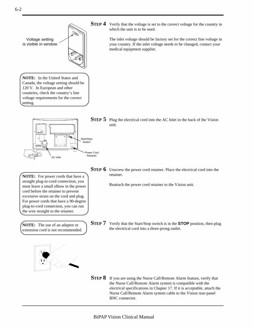
6-2
BiPAP Vision Clinical Manual
STEP 7 Verify that the Start/Stop switch is in the STOP position, then plugthe electrical cord into a three-prong outlet.
NOTE: The use of an adaptor orextension cord is not recommended.
NOTE: In the United States andCanada, the voltage setting should be120 V. In European and othercountries, check the country’s linevoltage requirements for the correctsetting.
AC Inlet
580123
Oxygen Inlet Pressure Range: 50 to 100 psig
Model # 582080
Start/StopSwitch
580NEW
100 - 240 V - T6.3 A, 250 V, 5 x 20 mm
100 - 240 V , 50/60 Hz
CLASS ITYPE BF
3.0 A Max.
WARNING: Disconnect power supply before servicing.
WARNING: For continued protection against risk of fire, replace with same type and rating of fuse.
WARNING: Equipment not suitable for use in the presence of flammable anaesthetic mixture.
WARNING: Proper grounding is essential for safety.
CAUTION: Federal law restricts this device to sale by or on the order of a physician.CAUTION: Do not immerse the device.
Warnings & Cautions
NRTL/C
¤ VD E
0123
115V Serial #
Power CordRetainer
STEP 6 Unscrew the power cord retainer. Place the electrical cord into theretainer.
Reattach the power cord retainer to the Vision unit.
115V
Voltage settingis visible in window
STEP 4 Verify that the voltage is set to the correct voltage for the country inwhich the unit is to be used.
The inlet voltage should be factory set for the correct line voltage inyour country. If the inlet voltage needs to be changed, contact yourmedical equipment supplier.
STEP 5 Plug the electrical cord into the AC Inlet in the back of the Visionunit.
NOTE: For power cords that have astraight plug-to-cord connection, youmust leave a small elbow in the powercord before the retainer to preventexcessive strain on the cord and plug.For power cords that have a 90-degreeplug-to-cord connection, you can runthe wire straight to the retainer.
STEP 8 If you are using the Nurse Call/Remote Alarm feature, verify thatthe Nurse Call/Remote Alarm system is compatible with theelectrical specifications in Chapter 17. If it is acceptable, attach theNurse Call/Remote Alarm system cable to the Vision rear-panelBNC connector.

6-3
BiPAP Vision Clinical Manual
STEP 1 Turn the Start/Stop Switch to the START position.
SYSTEM SELF TEST
IN PROGRESS
The Vision unit initiates the self-test, which takes from 15to 60 seconds.
6.2 Starting the Vision System
After completing the self-test, the unitdisplays the Set Up screen.
The Set Up screen contains soft keysto run the Exhalation Port Test and tochange languages.
The bottom of the graphic displayshows the total number of operatinghours and instructions to exit the Set-up Screen.
The Exhalation Port Test characterizes the patient circuit by analyzing the leakrate of the exhalation port. During the test, the system learns the intentionalexhalation port leak over the complete pressure range. The learned leak valueis then stored in system memory and is used to perform leak calculations andprovide an accurate display of patient leak and tidal volume in the Data DisplayArea. When a test is performed successfully, the Data Display shows theunintentional leak. The display will appear as “Pt. Leak” in the Data DisplayArea. If the test is not performed or cannot be completed successfully, thesystem is unable to accurately know the intentional leak and will display thetotal leak value (intentional + unintentional). The display will appear as “Tot.Leak” in the Data Display Area.
Test Exh
Port
Languages
TOTAL OPERATING TIME: 22 HRS
PRESS "MONITORING" TO EXIT
NOTE: The Exhalation Port Test isrecommended before each use, withcircuit changes, or with changes in theexhalation port. Completing the testensures the accuracy of leak calcula-tions and displays.
WARNING: Failure to perform theExhalation Port Test prior to initializ-ing therapy may result in inaccurateestimated tidal volume readings andfailure of the Low Minute VentilationAlarm to sound at settings below3 L/min. If an emergency situationrequires initiation of therapy withoutperforming the Exhalation Port Test,the Exhalation Port Test should beperformed as soon as possible after thepatient has been stabilized.

6-4
BiPAP Vision Clinical Manual
NOTE: To cancel the test at anytime, press the Cancel Test soft key.
EXHALATION PORT TEST
INSTRUCTIONS:
1. INSTALL CIRCUIT WITH EXHALATION DEVICE.
2. OCCLUDE CIRCUIT OUTLET.
3. PRESS "START TEST" WHEN READY.
4. KEEP TUBING OCCLUDED UNTIL TEST IS
COMPLETE.
Test Exh
Port
Languages
Start
Test
Cancel
Test
PRESS "MONITORING" TO EXIT
STEP 4 Press the Start Test soft key to initiate the Exhalation Port Test.The test will take approximately 15 seconds to complete.
Test Exh
Port
Languages
TOTAL OPERATING TIME: 22 HRS
PRESS <<MONITORING>> TO EXIT
The Test Exh Port descriptor ishighlighted; the system displays theTest Exh Port Screen.
The screen provides instructions toperform the test.
STEP 2 Press the Test Exh Port soft key.
STEP 3 Verify the assembly of the patient circuit. Completely occlude themask or circuit outlet during the test sequence.
NOTE: The exhalation port must beconnected to the circuit to successfullycomplete the Exhalation Port Test.
NOTE: If the exhalation port isdesigned as an integral part of themask, the mask must be attached whenperforming the Exhalation Port Test.
NOTE: When using a Spectrum® FullFace Mask, the preferred technique totest the exhalation port is to removethe mask and occlude the maskconnection port of the exhalationvalve. The Spectrum Full Face Maskuses a fresh air entrainment valve thatmay interfere with the Exhalation PortTest.
EXHALATION PORT TEST
INSTRUCTIONS:
1. INSTALL CIRCUIT WITH EXHALATION DEVICE.
2. OCCLUDE CIRCUIT OUTLET.
3. PRESS "START TEST" WHEN READY.
4. KEEP TUBING OCCLUDED UNTIL TEST IS
COMPLETE.
Test Exh
Port
Languages
Start
Test
Cancel
Test
PRESS "MONITORING" TO EXIT

6-5
BiPAP Vision Clinical Manual
STEP 5A Status: Test Complete.
Press the MONITORING hard key to begin system operation.
The system begins operation in thelast mode and at the settings in usebefore the unit was powered down.
Test Exh
Port
Languages
EXHALATION PORT TEST
INSTRUCTIONS:
1. INSTALL CIRCUIT WITH EXHALATION DEVICE.
2. OCCLUDE CIRCUIT OUTLET.
3. PRESS "START TEST" WHEN READY.
4. KEEP TUBING OCCLUDED UNTIL TEST IS
COMPLETE.
TEST STATUS: TEST COMPLETE
MODE: S/T MONITORINGIPAP
15
cm H2O
cm H2O
EPAP
6
Rate
Options
Standby
12
BPM
%O2
55
%
VT 1000 ml PIP 15 cm H2OMinVent 14 L/min
P (cm H2O)
Vol (ml)
Flow (L/min)
set
EXHALATION PORT TEST
INSTRUCTIONS:
1. INSTALL CIRCUIT WITH EXHALATION DEVICE.
2. OCCLUDE CIRCUIT OUTLET.
3. PRESS "START TEST" WHEN READY.
4. KEEP TUBING OCCLUDED UNTIL TEST IS
COMPLETE.
TEST STATUS: TEST COMPLETE
Test Exh
Port
Languages
Start
Test
Cancel
Test
PRESS "MONITORING" TO EXIT
The system begins the Exhalation Leak Test.Three status messages are possible:
a. TEST COMPLETE—The circuit displays normal leakconditions at the exhalation port—See STEP 5A.
b. LOW FLOW, CHECK CIRCUIT, REPEAT TEST—See STEP 5B.
c. EXCESSIVE FLOW, CHECK CIRCUIT, REPEATTEST—See STEP 5C.
d. OCCLUDED EXHALATION PORT, CHECK CIR-CUIT, REPEAT TEST—See STEP 5D.
e. PROXLINE DISCONNECT, CHECK CIRCUIT,REPEAT TEST—See STEP 5E.
f. PRESSURE REGULATION ERROR, CHECK CIR-CUIT, REPEAT TEST—See STEP 5F.
g. INTERMITTENT EXCESSIVE FLOW, CHECKCIRCUIT, REPEAT TEST—See STEP 5G.

6-6
BiPAP Vision Clinical Manual
STEP 5CStatus: Excessive Flow. The circuit displays a higherthan normal leak rate at the exhalation port .
Potential causes:• Excess leak in circuit; check tubing and connectors• Not a tight seal; check seal at circuit outlet or mask during test
Repeat the test.
STEP 5DStatus: Occluded exhalation port. The leak rate wasless than predicted.
Potential causes:• No exhalation port; add exhalation port• Exhalation port blocked
Repeat the test.
STEP 5E Status: Proxline disconnect. The proximal pressure lineis disconnected.
Potential causes:• Disconnected proximal pressure line• Obstruction (possible kink) in circuit• Obstruction (possible kink) in proximal pressure line
Repeat the test.
STEP 5F Status: Pressure regulation error. The leak testpressures cannot be attained.
Potential causes:• An internal pressure line or sensor malfunction
Repeat the test.
STEP 5GStatus: Intermittent excessive flow. The leak rate wasintermittently high during the test.
Potential causes:• The circuit was occluded, but the circuit end was opened or poorly
sealed during the test
STEP 5B Status: Low Flow. The leak rate was intermittently lowduring the test.
Potential causes:• The exhalation port was open but then partially blocked during the
test
Repeat the test.
STEP 6 Complete the Performance Verification in Chapter 7before each new patient setup.
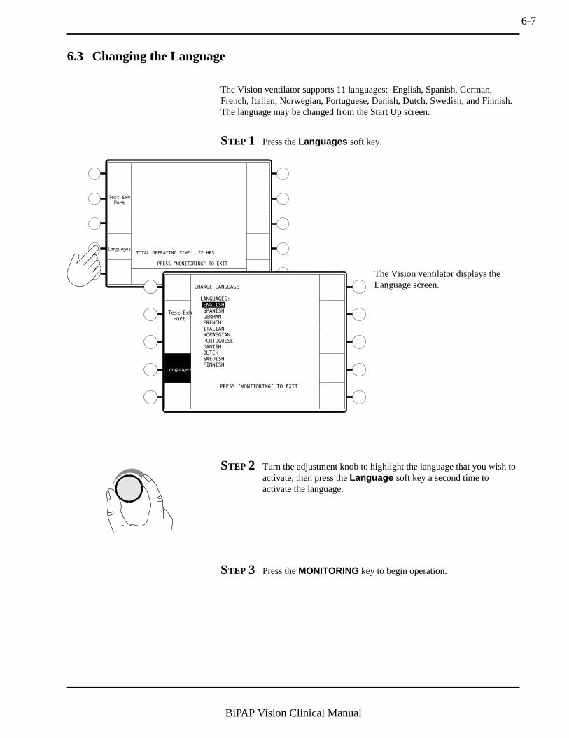
6-7
BiPAP Vision Clinical Manual
6.3 Changing the Language
The Vision ventilator supports 11 languages: English, Spanish, German,French, Italian, Norwegian, Portuguese, Danish, Dutch, Swedish, and Finnish.The language may be changed from the Start Up screen.
STEP 1 Press the Languages soft key.
Test Exh
Port
Languages
PRESS "MONITORING" TO EXIT
TOTAL OPERATING TIME: 22 HRS
Test Exh
Port
PRESS "MONITORING" TO EXIT
CHANGE LANGUAGE
LANGUAGES:
ENGLISH
SPANISH
GERMAN
FRENCH
ITALIAN
NORWEGIAN
PORTUGUESE
DANISH
DUTCH
SWEDISH
FINNISH
Languages
The Vision ventilator displays theLanguage screen.
STEP 2 Turn the adjustment knob to highlight the language that you wish toactivate, then press the Language soft key a second time toactivate the language.
STEP 3 Press the MONITORING key to begin operation.

6-8
BiPAP Vision Clinical Manual
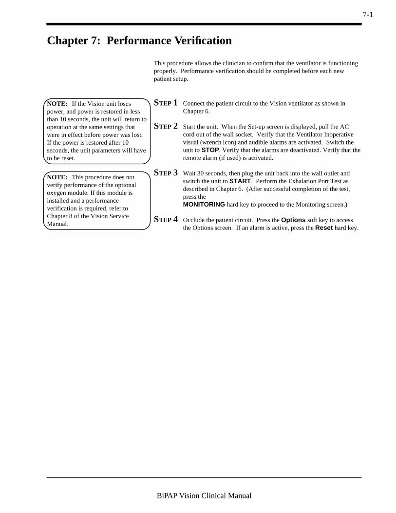
7-1
BiPAP Vision Clinical Manual
Chapter 7: Performance Verification
STEP 1 Connect the patient circuit to the Vision ventilator as shown inChapter 6.
STEP 2 Start the unit. When the Set-up screen is displayed, pull the ACcord out of the wall socket. Verify that the Ventilator Inoperativevisual (wrench icon) and audible alarms are activated. Switch theunit to STOP. Verify that the alarms are deactivated. Verify that theremote alarm (if used) is activated.
STEP 3 Wait 30 seconds, then plug the unit back into the wall outlet andswitch the unit to START. Perform the Exhalation Port Test asdescribed in Chapter 6. (After successful completion of the test,press theMONITORING hard key to proceed to the Monitoring screen.)
STEP 4 Occlude the patient circuit. Press the Options soft key to accessthe Options screen. If an alarm is active, press the Reset hard key.
This procedure allows the clinician to confirm that the ventilator is functioningproperly. Performance verification should be completed before each newpatient setup.
NOTE: If the Vision unit losespower, and power is restored in lessthan 10 seconds, the unit will return tooperation at the same settings thatwere in effect before power was lost.If the power is restored after 10seconds, the unit parameters will haveto be reset.
NOTE: This procedure does notverify performance of the optionaloxygen module. If this module isinstalled and a performanceverification is required, refer toChapter 8 of the Vision ServiceManual.

7-2
BiPAP Vision Clinical Manual
STEP 5 Press the Test Alarms soft key to verify that both the audible toneand the alarm messages activate for all available alarms. TheVentilator Inoperative and Check Ventilator icons should illuminateduring the test. The Vision front panel should look likeFigure 7-1
Figure 7-1. The Alarm Test Screen.
Illuminated
Alarm Messagesin Mode/Message
Area
P (cm H2O)
Vol (ml)
Flow (L/min)
OPERATING IN: S/T
TOTAL OPERATING TIME: 50 HRS
PRESS "MONITORING" TO EXIT
Error
Messages
Time at P
49
Reset
Test
Alarms
System
Info
Bar
Graph
Brightness
Contrast
Invert
hrs
ALARM
O2 Flow
Lo MinVent
Hi Rate
Lo Rate
Hi P
Lo P
Apnea
ProxLine Disc
Low Leak
P Regulation
Disconnect
NOTE: Each alarm function has bothan audible and visual component.Verify that both components are activeduring the alarm test. If eithercomponent is not active, have theventilator serviced.
STEP 6 If the CPAP Mode is active, press the MODE hard key, select the S/T Mode key, and set the parameters as shown below. Activate thenew mode. If the S/T Mode is active, press the MONITORINGhard key then press the PARAMETERS hard key. In either case,set the parameters as follows:
IPAP = 15 cm H2OEPAP = 5 cm H2ORate= 16 BPMTimed Insp = 1.0 secIPAP Rise Time = 0.1 sec
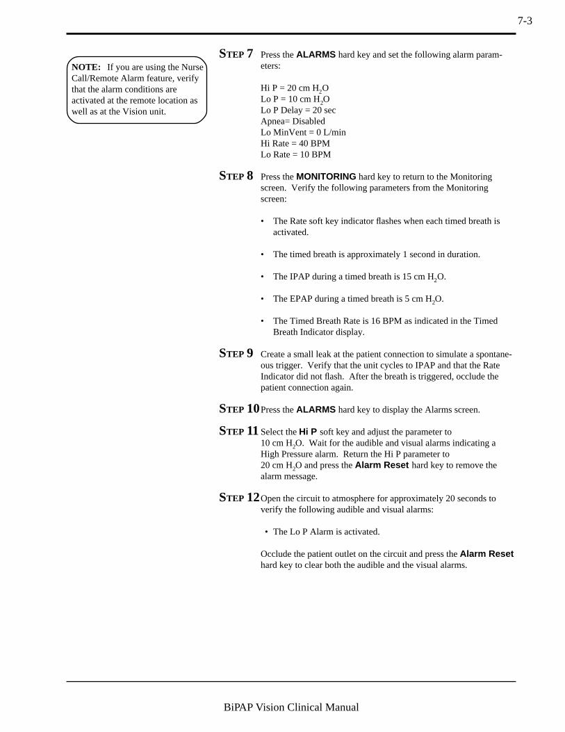
7-3
BiPAP Vision Clinical Manual
STEP 7 Press the ALARMS hard key and set the following alarm param-eters:
Hi P = 20 cm H2OLo P = 10 cm H2OLo P Delay = 20 secApnea= DisabledLo MinVent = 0 L/minHi Rate = 40 BPMLo Rate = 10 BPM
STEP 8 Press the MONITORING hard key to return to the Monitoringscreen. Verify the following parameters from the Monitoringscreen:
• The Rate soft key indicator flashes when each timed breath isactivated.
• The timed breath is approximately 1 second in duration.
• The IPAP during a timed breath is 15 cm H2O.
• The EPAP during a timed breath is 5 cm H2O.
• The Timed Breath Rate is 16 BPM as indicated in the TimedBreath Indicator display.
STEP 9 Create a small leak at the patient connection to simulate a spontane-ous trigger. Verify that the unit cycles to IPAP and that the RateIndicator did not flash. After the breath is triggered, occlude thepatient connection again.
STEP 10Press the ALARMS hard key to display the Alarms screen.
STEP 11Select the Hi P soft key and adjust the parameter to10 cm H2O. Wait for the audible and visual alarms indicating aHigh Pressure alarm. Return the Hi P parameter to20 cm H2O and press the Alarm Reset hard key to remove thealarm message.
STEP 12Open the circuit to atmosphere for approximately 20 seconds toverify the following audible and visual alarms:
• The Lo P Alarm is activated.
Occlude the patient outlet on the circuit and press the Alarm Resethard key to clear both the audible and the visual alarms.
NOTE: If you are using the NurseCall/Remote Alarm feature, verifythat the alarm conditions areactivated at the remote location aswell as at the Vision unit.

7-4
BiPAP Vision Clinical Manual
STEP 13Press the Apnea soft key and adjust the parameter to 20 sec.Maintain the occlusion of the patient connection for a minimum of20 seconds to verify that the audible tone and the Apnea AlarmMessage are activated. Adjust the Apnea setting to the Disabledsetting. Press the Alarm Reset key to clear the visual alarms.
The Vision ventilator is ready for use if it has successfully passed the Perfor-mance Verification.
Adjust the Vision ventilator to the appropriate patient settings after the Perfor-mance Verification and before patient use.
WARNING: The Vision ventilatorrequires service if it fails to performwithin the stated specifications.

8-1
BiPAP Vision Clinical Manual
Chapter 8: CPAP Mode
8.1 Overview The CPAP Mode delivers Continuous Positive Airway Pressure to the patientcircuit.
The active CPAP controls are:
• CPAP• %O2
During operation, the Monitoring screen continuously displays measured datafor:
• CPAP• Rate (total breaths per minute)
The Data Display Area (in Monitoring screen) displays:
• Estimated Exhaled Tidal Volume• Estimated Minute Ventilation• Peak Inspiratory Pressure
In the Modify Parameters screen, the Data Display Area also displays:
• Ti/Ttot• Leak (Patient or Total)
The Graphic Display Area shows real-time graphic displays for:
• Pressure• Tidal Volume• Flow
Alarms are available and are immediately activated once the mode is inoperation. Alarms for the CPAP Mode are accessed from the Alarms screenwhen the CPAP Mode is activated.
NOTE: If the Vision unit losespower, and power is restored in lessthan 10 seconds, the unit will return tooperation at the same settings thatwere in effect before power was lost.

8-2
BiPAP Vision Clinical Manual
8.2 Changing to the CPAP Mode
STEP 2 Press the CPAP soft key.
CHANGE MODE
CPAP
OPERATING IN: S/TP (cm H2O)
Vol (ml)
Flow (L/min)
MODE: S/T MONITORINGIPAP
15
cm H2O
cm H2O
EPAP
6
Rate
Options
Standby
12
BPM
%O2
%
VT 1000 ml PIP 15 cm H2OMinVent 14 L/min
PS = 9 cm H2OP (cm H
2O)
Vol (ml)
Flow (L/min)
55set
CHANGE MODE
CPAP
OPERATING IN: S/TP (cm H2O)
Vol (ml)
Flow (L/min)
The Change Mode screen is displayed. Available modesare displayed in the right column ofdescriptors.
STEP 1 If the unit is operating in the S/T Mode, press the MODE Key.
P (cm H2O)
Vol (ml)
Flow (L/min)
8set
OPERATING IN: S/T
NEW MODE: CPAP
SET UP PARAMETERS
REVIEW ALARM LIMITS AFTER NEW MODE ACTIVE
CPAP
cm H2O
ACTIVATE
NEW MODE
The New Mode screen for the CPAP Mode isdisplayed.
This screen allows you to review or make adjustments tothe CPAP parameters before activating the new mode.
WARNING: At low baseline CPAP pressures, the flow through the exhalation port may not adequately clear allexhaled gas from the tubing. Some rebreathing may occur. Refer to Chapter 2 for guidelines onrebreathing.
NOTE: The ACTIVATE NEW MODE descriptor flashes to indicate that the CPAP Mode and selected parameters arenot active until you press the ACTIVATE NEW MODE soft key.
NOTE: The S/T Mode remains active and is displayed in the graphics area on the screen until the ACTIVATE NEWMODE soft key is pressed.

8-3
BiPAP Vision Clinical Manual
STEP 3 Press the soft key corresponding to the parameter you wish to adjust.
The selected parameter is highlighted.
Increment: 1 cm H2O
Range: 4 to 20 cm H2O
%O2
21
%
set
CPAP
4
cm H2O
set
Adjusting CPAP
P (cm H2O)
Vol (ml)
Flow (L/min)
NEW MODE: CPAP
SET UP PARAMETERS
REVIEW ALARM LIMITS AFTER NEW MODE ACTIVE
CPAP
cm H2O
ACTIVATE
NEW MODE
8set
OPERATING IN: S/T
CPAP
STEP 4 Turn the adjustment knob to modify the selected parameter.
STEP 5 When you have completed parameter adjustments, press the flashingACTIVATE NEW MODE soft key.
P (cm H2O)
Vol (ml)
Flow (L/min)
OPERATING IN: S/T
NEW MODE: CPAP
SET UP PARAMETERS
REVIEW ALARM LIMITS AFTER NEW MODE ACTIVE
CPAP
cm H2O
8set
ACTIVATE
NEW MODE
MODE: CPAP MONITORINGCPAP
8
cm H2O
Rate
Options
Standby
12
BPM
%O2
%
VT 700 ml PIP 8 cm H2OMinVent 14 L/min
P (cm H2O)
Vol (ml)
Flow (L/min)
55set
NOTE: When CPAP settings are determined and the mode is activated, press the ALARMS key to view the CPAPalarm settings. See Section 8.4, “Modifying Alarm Parameters,” for instructions.
If no user interaction occurs for a 3-minute time span, the unit defaults to the Monitoring screen.
The unit begins CPAP delivery and the display immedi-ately changes to the Monitoring screen.
Verify CPAP operation at the intended parameters byviewing the parameter and graphics displays on the screen.The Mode/Message Area should indicate CPAP.
Press the CPAP soft key and turnthe adjustment knob.
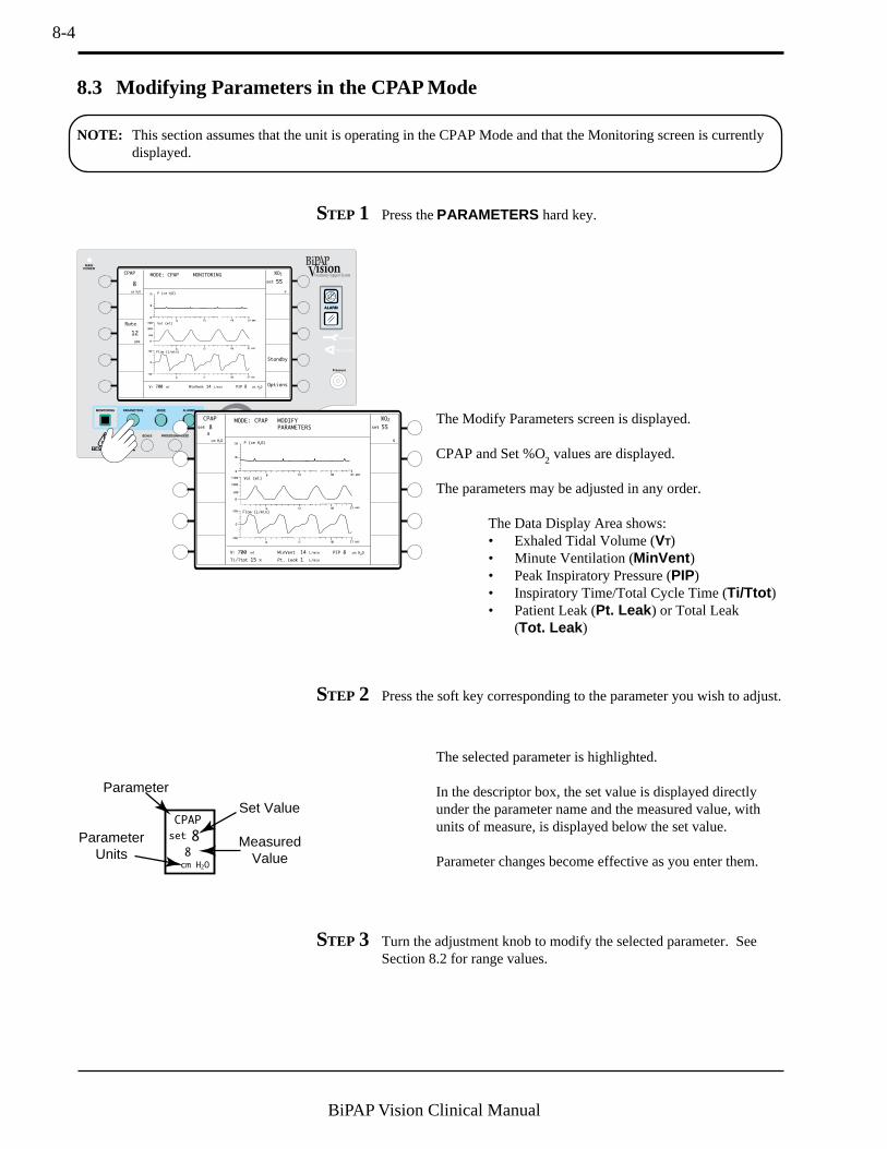
8-4
BiPAP Vision Clinical Manual
8.3 Modifying Parameters in the CPAP Mode
The Modify Parameters screen is displayed.
CPAP and Set %O2 values are displayed.
The parameters may be adjusted in any order.
The Data Display Area shows:• Exhaled Tidal Volume (VT)• Minute Ventilation (MinVent )• Peak Inspiratory Pressure (PIP)• Inspiratory Time/Total Cycle Time (Ti/Ttot )• Patient Leak (Pt. Leak ) or Total Leak
(Tot. Leak )
MODE: CPAP MONITORINGCPAP
8
cm H2O
Rate
Options
Standby
12
BPM
%O2
%
VT 700 ml PIP 8 cm H2OMinVent 14 L/min
P (cm H2O)
Vol (ml)
Flow (L/min)
55set
NOTE: This section assumes that the unit is operating in the CPAP Mode and that the Monitoring screen is currentlydisplayed.
STEP 1 Press the PARAMETERS hard key.
P (cm H2O)
Vol (ml)
Flow (L/min)
MODE: CPAP MODIFY
PARAMETERS
CPAP
cm H2O
%O2
%
8
8
set 55set
VT 700 ml PIP 8 cm H2OMinVent 14 L/min
Ti/Ttot 15 % Pt. Leak 1 L/min
STEP 2 Press the soft key corresponding to the parameter you wish to adjust.
The selected parameter is highlighted.
In the descriptor box, the set value is displayed directlyunder the parameter name and the measured value, withunits of measure, is displayed below the set value.
Parameter changes become effective as you enter them.
STEP 3 Turn the adjustment knob to modify the selected parameter. SeeSection 8.2 for range values.
CPAP
8
cm H2O
set
8
Parameter
Set Value
MeasuredValue
ParameterUnits
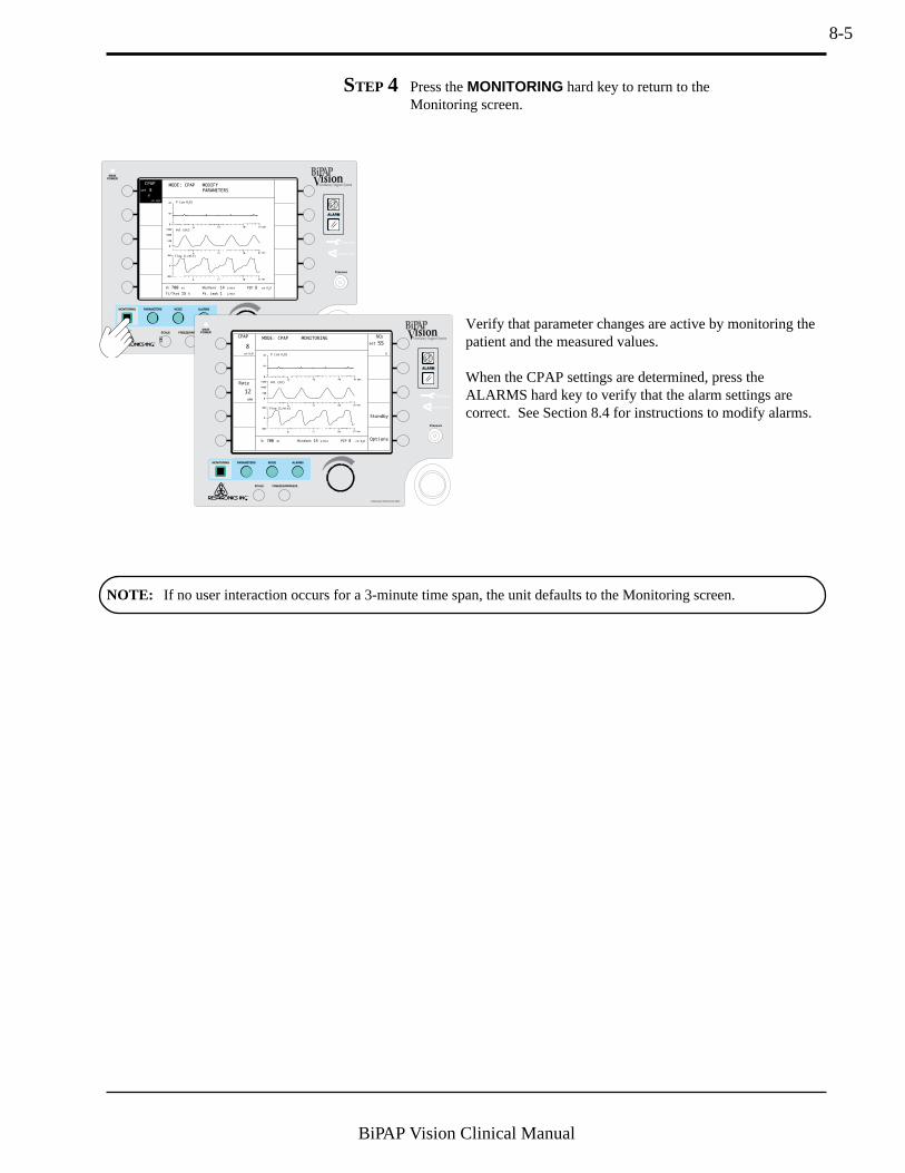
8-5
BiPAP Vision Clinical Manual
STEP 4 Press the MONITORING hard key to return to theMonitoring screen.
P (cm H2O)
Vol (ml)
Flow (L/min)
MODE: CPAP MODIFY
PARAMETERS
VT 700 ml MinVent 14 L/min
Ti/Ttot 15 % Pt. Leak 1 L/min
CPAP
cm H2O
8
8
set
PIP 8 cm H2O
MODE: CPAP MONITORINGCPAP
8
cm H2O
Rate
Options
Standby
12
BPM
%O2
%
VT 700 ml PIP 8 cm H2OMinVent 14 L/min
P (cm H2O)
Vol (ml)
Flow (L/min)
55set
NOTE: If no user interaction occurs for a 3-minute time span, the unit defaults to the Monitoring screen.
Verify that parameter changes are active by monitoring thepatient and the measured values.
When the CPAP settings are determined, press theALARMS hard key to verify that the alarm settings arecorrect. See Section 8.4 for instructions to modify alarms.
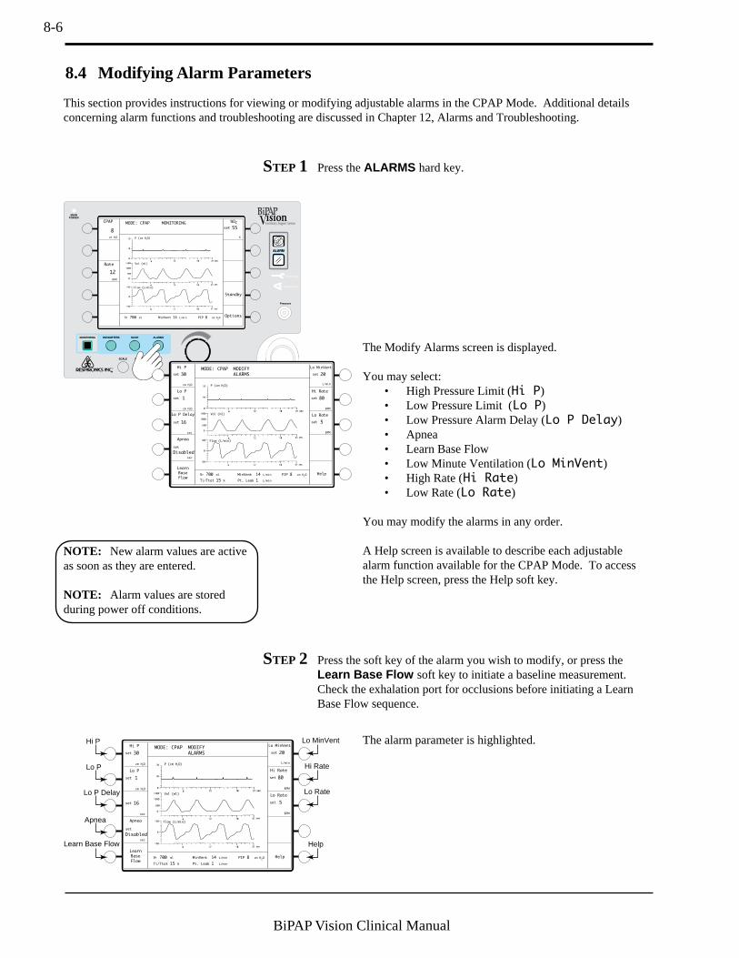
8-6
BiPAP Vision Clinical Manual
8.4 Modifying Alarm Parameters
STEP 1 Press the ALARMS hard key.
MODE: CPAP MONITORINGCPAP
8
cm H2O
Rate
Options
Standby
12
BPM
%O2
%
VT 700 ml PIP 8 cm H2OMinVent 14 L/min
P (cm H2O)
Vol (ml)
Flow (L/min)
55set
MODE: CPAP MODIFY
ALARMS
Hi P Lo MinVent
30
cm H2O
VT 700 ml PIP 8 cm H2OMinVent 14 L/min
Ti/Ttot 15 % Pt. Leak 1 L/min
set 20set
Lo P
1
cm H2O
set
Hi Rate
80
BPM
set
Lo Rate
5
BPM
set
Lo P Delay
Learn
Base
Flow
16
sec
L/min
set
Apnea
Help
Disabled
sec
set
P (cm H2O)
Vol (ml)
Flow (L/min)
STEP 2 Press the soft key of the alarm you wish to modify, or press theLearn Base Flow soft key to initiate a baseline measurement.Check the exhalation port for occlusions before initiating a LearnBase Flow sequence.
MODE: CPAP MODIFY
ALARMS
Hi P
30
cm H2O
VT 700 ml PIP 8 cm H2OMinVent 14 L/min
Ti/Ttot 15 % Pt. Leak 1 L/min
set
Lo P
1
cm H2O
set
Learn
Base
Flow
16
sec
set
Apnea
Help
Disabled
sec
set
Lo MinVent
20set
Hi Rate
80
BPM
set
Lo Rate
5
BPM
set
L/minP (cm H
2O)
Vol (ml)
Flow (L/min)
Hi P
Lo P
Lo P Delay
Apnea
HelpLearn Base Flow
Lo MinVent
Hi Rate
Lo Rate
The alarm parameter is highlighted.
This section provides instructions for viewing or modifying adjustable alarms in the CPAP Mode. Additional detailsconcerning alarm functions and troubleshooting are discussed in Chapter 12, Alarms and Troubleshooting.
NOTE: New alarm values are activeas soon as they are entered.
NOTE: Alarm values are storedduring power off conditions.
The Modify Alarms screen is displayed.
You may select:• High Pressure Limit (Hi P)• Low Pressure Limit (Lo P)• Low Pressure Alarm Delay (Lo P Delay)• Apnea• Learn Base Flow• Low Minute Ventilation (Lo MinVent)• High Rate (Hi Rate)• Low Rate (Lo Rate)
You may modify the alarms in any order.
A Help screen is available to describe each adjustablealarm function available for the CPAP Mode. To accessthe Help screen, press the Help soft key.
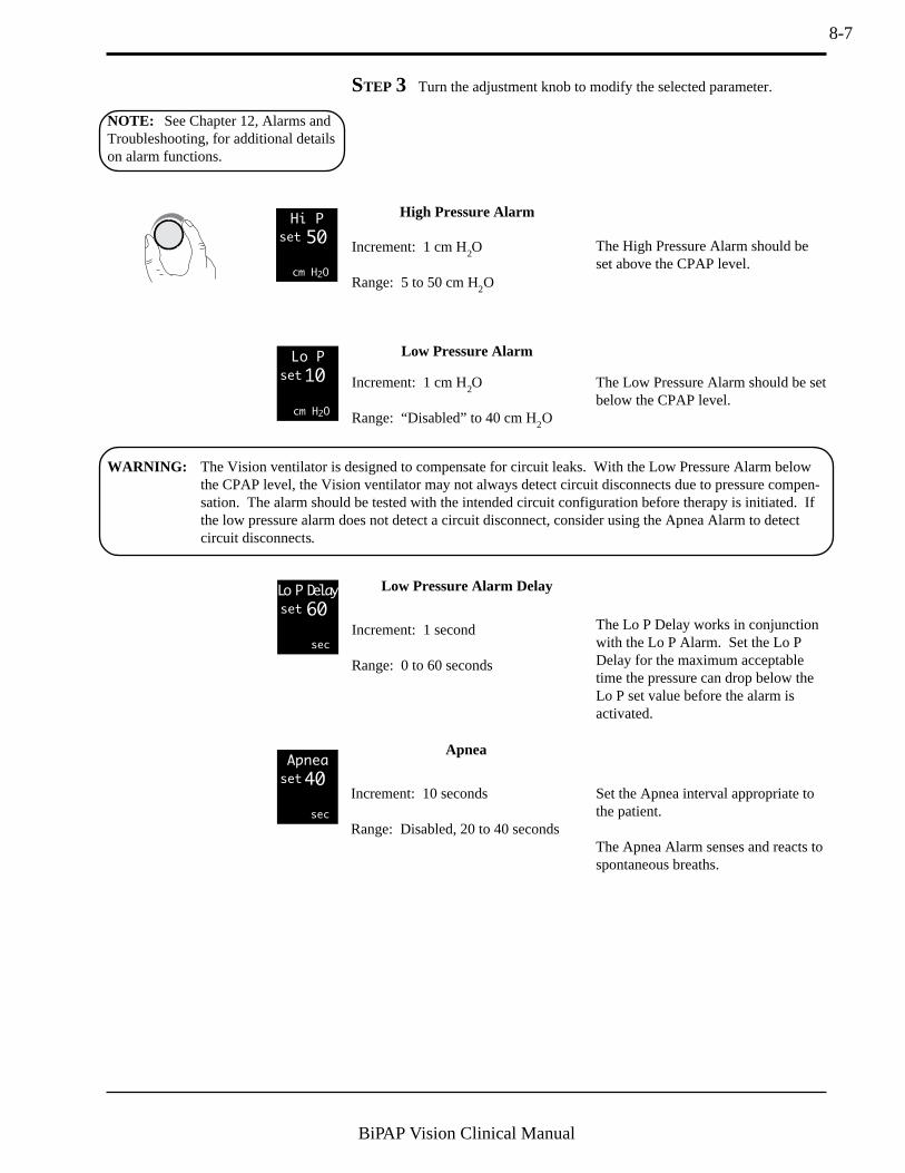
8-7
BiPAP Vision Clinical Manual
High Pressure Alarm
Increment: 1 cm H2O
Range: 5 to 50 cm H2O
Hi P
50
cm H2O
set
STEP 3 Turn the adjustment knob to modify the selected parameter.
Low Pressure Alarm
Increment: 1 cm H2O
Range: “Disabled” to 40 cm H2O
Low Pressure Alarm Delay
Increment: 1 second
Range: 0 to 60 seconds
Lo P
10
cm H2O
set
Lo P Delay
60
sec
set
Apnea
40
sec
set
Apnea
Increment: 10 seconds
Range: Disabled, 20 to 40 seconds
The High Pressure Alarm should beset above the CPAP level.
The Low Pressure Alarm should be setbelow the CPAP level.
WARNING: The Vision ventilator is designed to compensate for circuit leaks. With the Low Pressure Alarm belowthe CPAP level, the Vision ventilator may not always detect circuit disconnects due to pressure compen-sation. The alarm should be tested with the intended circuit configuration before therapy is initiated. Ifthe low pressure alarm does not detect a circuit disconnect, consider using the Apnea Alarm to detectcircuit disconnects.
Set the Apnea interval appropriate tothe patient.
The Apnea Alarm senses and reacts tospontaneous breaths.
NOTE: See Chapter 12, Alarms andTroubleshooting, for additional detailson alarm functions.
The Lo P Delay works in conjunctionwith the Lo P Alarm. Set the Lo PDelay for the maximum acceptabletime the pressure can drop below theLo P set value before the alarm isactivated.
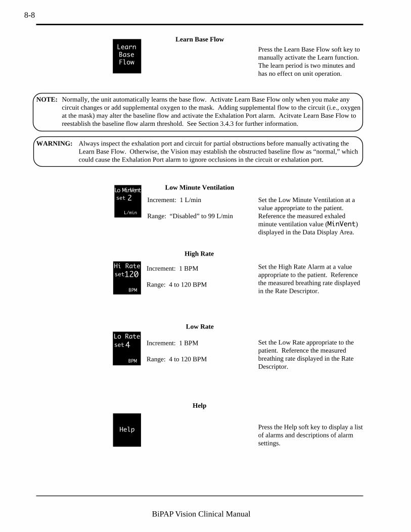
8-8
BiPAP Vision Clinical Manual
Increment: 1 BPM
Range: 4 to 120 BPM
High Rate
Increment: 1 BPM
Range: 4 to 120 BPM
Low Rate
Hi Rate
120
BPM
set
Lo Rate
4
BPM
set
Set the High Rate Alarm at a valueappropriate to the patient. Referencethe measured breathing rate displayedin the Rate Descriptor.
Set the Low Rate appropriate to thepatient. Reference the measuredbreathing rate displayed in the RateDescriptor.
Low Minute Ventilation
Increment: 1 L/min
Range: “Disabled” to 99 L/min
Lo MinVent
2
L/min
set Set the Low Minute Ventilation at avalue appropriate to the patient.Reference the measured exhaledminute ventilation value (MinVent)displayed in the Data Display Area.
Help
Help
Press the Help soft key to display a listof alarms and descriptions of alarmsettings.
Learn
Base
Flow
Learn Base Flow
Press the Learn Base Flow soft key tomanually activate the Learn function.The learn period is two minutes andhas no effect on unit operation.
NOTE: Normally, the unit automatically learns the base flow. Activate Learn Base Flow only when you make anycircuit changes or add supplemental oxygen to the mask. Adding supplemental flow to the circuit (i.e., oxygenat the mask) may alter the baseline flow and activate the Exhalation Port alarm. Acitvate Learn Base Flow toreestablish the baseline flow alarm threshold. See Section 3.4.3 for further information.
WARNING: Always inspect the exhalation port and circuit for partial obstructions before manually activating theLearn Base Flow. Otherwise, the Vision may establish the obstructed baseline flow as “normal,” whichcould cause the Exhalation Port alarm to ignore occlusions in the circuit or exhalation port.
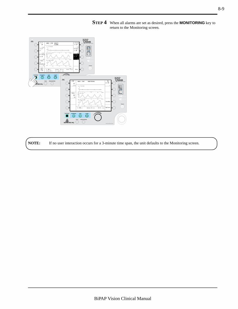
8-9
BiPAP Vision Clinical Manual
STEP 4 When all alarms are set as desired, press the MONITORING key toreturn to the Monitoring screen.
MODE: CPAP MODIFY
ALARMS
Hi P
30
cm H2O
VT 700 ml PIP 8 cm H2OMinVent 14 L/min
Ti/Ttot 15 % Pt. Leak 1 L/min
Lo P
cm H2O
set
Lo P Delay
Learn
Base
Flow
16
sec
set
Apnea
Help
Disabled
sec
set
Lo MinVent
20set
Hi Rate
80
BPM
set
L/min
Lo Rate
5
BPM
set
P (cm H2O)
Vol (ml)
Flow (L/min)
NOTE: If no user interaction occurs for a 3-minute time span, the unit defaults to the Monitoring screen.
MODE: CPAP MONITORINGCPAP
8
cm H2O
Rate
Options
Standby
12
BPM
%O2
%
VT 700 ml PIP 8 cm H2OMinVent 14 L/min
P (cm H2O)
Vol (ml)
Flow (L/min)
55set

8-10
BiPAP Vision Clinical Manual
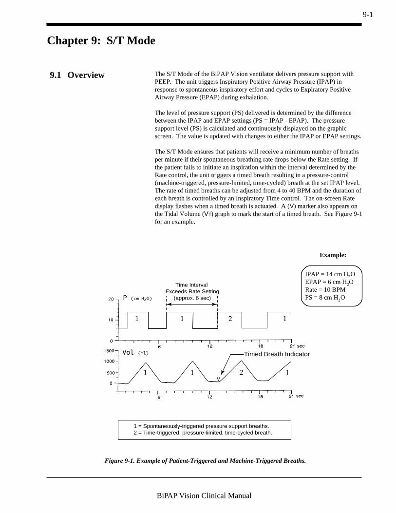
9-1
BiPAP Vision Clinical Manual
Chapter 9: S/T Mode
The S/T Mode of the BiPAP Vision ventilator delivers pressure support withPEEP. The unit triggers Inspiratory Positive Airway Pressure (IPAP) inresponse to spontaneous inspiratory effort and cycles to Expiratory PositiveAirway Pressure (EPAP) during exhalation.
The level of pressure support (PS) delivered is determined by the differencebetween the IPAP and EPAP settings (PS = IPAP - EPAP). The pressuresupport level (PS) is calculated and continuously displayed on the graphicscreen. The value is updated with changes to either the IPAP or EPAP settings.
The S/T Mode ensures that patients will receive a minimum number of breathsper minute if their spontaneous breathing rate drops below the Rate setting. Ifthe patient fails to initiate an inspiration within the interval determined by theRate control, the unit triggers a timed breath resulting in a pressure-control(machine-triggered, pressure-limited, time-cycled) breath at the set IPAP level.The rate of timed breaths can be adjusted from 4 to 40 BPM and the duration ofeach breath is controlled by an Inspiratory Time control. The on-screen Ratedisplay flashes when a timed breath is actuated. A (V) marker also appears onthe Tidal Volume (VT) graph to mark the start of a timed breath. See Figure 9-1for an example.
9.1 Overview
Vol (ml)
P (cm H2O)
Timed Breath Indicator
Time Interval Exceeds Rate Setting
(approx. 6 sec)
1 1 1
1
2
1 1 2
1 = Spontaneously-triggered pressure support breaths.2 = Time-triggered, pressure-limited, time-cycled breath.
Figure 9-1. Example of Patient-Triggered and Machine-Triggered Breaths.
IPAP = 14 cm H2OEPAP = 6 cm H2ORate = 10 BPMPS = 8 cm H2O
Example:
9-2
BiPAP Vision Clinical Manual
The active S/T controls include:
• IPAP• EPAP• Rate
• Timed Inspiration• IPAP Rise Time• %O2
During operation, the Monitoring screen continuously displays measured datafor:
• IPAP• EPAP• Rate (total breaths per minute)
The Data Display Area (in the Monitoring screen) displays:
• Estimated Exhaled Tidal Volume• Estimated Minute Ventilation• Peak Inspiratory Pressure
In the Modify Parameters screen, the Data Display Area also displays:
• Ti/Ttot• Leak (Patient or Total)• % Patient-Triggered Breaths
The Graphic Display Area shows real-time graphic displays for:
• Pressure• Tidal Volume• Flow
Alarms are available and are immediately activated once the mode is inoperation. Alarms for the S/T Mode are accessed from the Alarms screen whenthe S/T Mode is activated.
NOTE: If the Vision unit losespower, and power is restored in lessthan 10 seconds, the unit will return tooperation at the same settings thatwere in effect before power was lost.

9-3
BiPAP Vision Clinical Manual
9.2 Changing to the S/T Mode
MODE: CPAP MONITORINGCPAP
8
cm H2O
Rate
Options
Standby
12
BPM
%O2
%
VT 700 ml PIP 8 cm H2OMinVent 14 L/min
P (cm H2O)
Vol (ml)
Flow (L/min)
55set
The Change Mode screen is displayed. Available modesare displayed in the right column of descriptors.
NOTE: The CPAP Mode remains active and is displayed in the Graphic Area on the screen until you press the ACTI-VATE NEW MODE soft key.
STEP 2 Press the S/T soft key.
CHANGE MODE
S/T
OPERATING IN: CPAPP (cm H2O)
Vol (ml)
Flow (L/min)
The New Mode/Set-up Parameters screen for theS/T Mode is displayed. You may select for adjustment:
• IPAP• EPAP• Rate• Timed Inspiration• IPAP Rise Time
STEP 1 If the unit is not operating in the S/T Mode, press the MODEhard key.
CHANGE MODE
S/T
OPERATING IN: CPAPP (cm H2O)
Vol (ml)
Flow (L/min)
P (cm H2O)
Vol (ml)
Flow (L/min)
NEW MODE: S/T
SET UP PARAMETERS
IPAP
cm H2O
IPAP
Rise Time
15set
EPAP
cm H2O
6set
Rate
OPERATING IN: CPAP
BPM
12set
0.1set
Timed Insp
sec
sec
3.0set
REVIEW ALARM LIMITS AFTER NEW MODE ACTIVE
ACTIVATE
NEW MODE
NOTE: The ACTIVATE NEW MODE descriptor flashes to indicate that the S/T Mode and selected parameters are notactive until you press the ACTIVATE NEW MODE soft key.

9-4
BiPAP Vision Clinical Manual
NOTE: IPAP cannot be set lower than EPAP. The Vision ventilator will signal with a soft click if you attempt to setIPAP lower than EPAP and will stop any further adjustment of the value.
IPAP
40
cm H2O
set Increment: 1 cm H2O
Range: 4 to 40 cm H2O
EPAP
20
cm H2O
set
Adjusting EPAP
Adjusting IPAP
Increment: 1 cm H2O
Range: 4 to 20 cm H2O
STEP 4 Turn the adjustment knob to modify the selected parameter.
STEP 3 Press the soft key corresponding to the parameter you wish to set.
The selected parameter is highlighted.P (cm H
2O)
Vol (ml)
Flow (L/min)
NEW MODE: S/T
SET UP PARAMETERS
IPAP
cm H2O
IPAP
Rise Time
15set
EPAP
cm H2O
6set
Rate
OPERATING IN: CPAP
BPM
12set
0.1set
Timed Insp
sec
sec
3.0set
REVIEW ALARM LIMITS AFTER NEW MODE ACTIVE
ACTIVATE
NEW MODE
IPAP
EPAP
Rate
Timed Insp
IPAP Rise Time
ACTIVATE
NEW MODE
The IPAP Control determines thepressure level during inspiration.
The EPAP Control establishes thebaseline pressure (PEEP).
NOTE: EPAP cannot be set higher than IPAP. The Vision ventilator will signal with a soft click if you attempt to setEPAP higher than IPAP and will stop any further adjustment of the value.
WARNING: At low EPAP pressures, the flow through the exhalation port may not adequately clear all exhaled gasfrom the tubing. Some rebreathing may occur. Refer to Chapter 2 for guidelines on rebreathing.
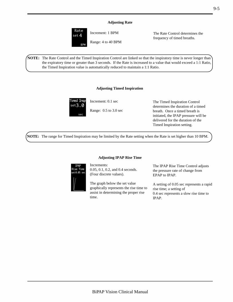
9-5
BiPAP Vision Clinical Manual
Adjusting IPAP Rise Time
15set0.05 sec
IPAP
Rise Time
Increments:0.05, 0.1, 0.2, and 0.4 seconds.(Four discrete values).
The graph below the set valuegraphically represents the rise time toassist in determining the proper risetime.
NOTE: The Rate Control and the Timed Inspiration Control are linked so that the inspiratory time is never longer thanthe expiratory time or greater than 3 seconds. If the Rate is increased to a value that would exceed a 1:1 Ratio,the Timed Inspiration value is automatically reduced to maintain a 1:1 Ratio.
Rate
4
BPM
set
Increment: 1 BPM
Range: 4 to 40 BPM
Adjusting Rate
Timed Insp
3.0
sec
set
Increment: 0.1 sec
Range: 0.5 to 3.0 sec
Adjusting Timed Inspiration
The Rate Control determines thefrequency of timed breaths.
The Timed Inspiration Controldetermines the duration of a timedbreath. Once a timed breath isinitiated, the IPAP pressure will bedelivered for the duration of theTimed Inspiration setting.
The IPAP Rise Time Control adjuststhe pressure rate of change fromEPAP to IPAP.
A setting of 0.05 sec represents a rapidrise time; a setting of0.4 sec represents a slow rise time toIPAP.
NOTE: The range for Timed Inspiration may be limited by the Rate setting when the Rate is set higher than 10 BPM.

9-6
BiPAP Vision Clinical Manual
Vol (ml)
P (cm H2O)
Flow (L/min)
NEW MODE: S/T
SET UP PARAMETERS
IPAP
cm H2O
IPAP
Rise Time
15set
EPAP
cm H2O
6set
OPERATING IN: CPAP
0.1set
Timed Insp
sec
sec
3.0set
REVIEW ALARM LIMITS AFTER NEW MODE ACTIVE
ACTIVATE
NEW MODE
Rate
BPM
12set
ACTIVATE
NEW MODE The unit begins operating in the S/T Mode and thedisplay changes to the Monitoring screen. Verify S/Toperation at the intended pressures by viewing themeasured values and graphics display on the screen.The Mode/Message Area should indicate S/T Mode.
Verify the desired pressure support level by observingthe graphic display and the Pressure Support (PS) valuedisplayed above the pressure graphic.
STEP 5 Press the flashing ACTIVATE NEW MODE soft key.
MODE: S/T MONITORINGIPAP
15
cm H2O
cm H2O
EPAP
6
Rate
Options
Standby
12
BPM
%O2
%
VT 1000 ml PIP 15 cm H2OMinVent 14 L/min
PS = 9 cm H2O
Vol (ml)
P (cm H2O)
Flow (L/min)
55set
NOTE: Once S/T settings are determined and the mode is activated, press the ALARMS hard key to view theS/T alarm settings. See Section 9.4 for detailed instructions.

9-7
BiPAP Vision Clinical Manual
NOTE: This section assumes that the S/T Monitoring screen is currently displayed.
STEP 1 Press the PARAMETERS hard key.
MODE: S/T MONITORINGIPAP
15
cm H2O
cm H2O
EPAP
6
Rate
Options
Standby
12
BPM
%O2
%
VT 1000 ml PIP 15 cm H2OMinVent 14 L/min
PS = 9 cm H2OP (cm H2O)
Vol (ml)
Flow (L/min)
55set
P (cm H2O)
Vol (ml)
Flow (L/min)
MODE: S/T MODIFY
PARAMETERS
IPAP
cm H2O
%O2
IPAP
Rise Time
%
15
15
set
EPAP
cm H2O
6
6
set
Rate
PS = 9 cm H2O
BPM
12
12
set
0.1set
Timed Insp
sec
sec
3.0set
55set
VT 700 ml PIP 8 cm H2OMinVent 14 L/min
Ti/Ttot 15 % Pt. Leak 1 L/min Pt. Trig 5 %
The Modify Parameters screen is displayed.
Available for modification:
• IPAP• EPAP• Rate
9.3 Modifying Parameters in the S/T Mode
STEP 2 Press the soft key corresponding to the parameter you wishto modify.
The selected parameter is highlighted.
In the Modify Parameters screen, the set value is displayeddirectly under the parameter name, and the measured valueand units of measure are displayed below the set value.
Parameter changes take effect as you enter them.
STEP 3 Turn the adjustment knob to modify the selected parameter.
See Section 9.2 for ranges.
• Timed Inspiration• %O2• IPAP Rise Time
The parameters may be modified in any order.
For reference while making changes, the Data Display Area shows:
• Estimated Tidal Volume (VT)• Estimated Minute Ventilation (MinVent )• Peak Inspiratory Pressure (PIP)• Inspiratory Time/Total Cycle Time (Ti/Ttot )• Patient Leak (Pt. Leak ) or Total Leak (Tot. Leak )• % Patient-Triggered Breaths (Pt. Trig )
EPAP
6
cm H2O
set
6
Parameter
Set Value
MeasuredValue
ParameterUnits
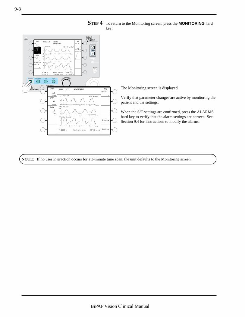
9-8
BiPAP Vision Clinical Manual
The Monitoring screen is displayed.
Verify that parameter changes are active by monitoring thepatient and the settings.
When the S/T settings are confirmed, press the ALARMShard key to verify that the alarm settings are correct. SeeSection 9.4 for instructions to modify the alarms.
MODE: S/T MODIFY
PARAMETERS
IPAP
cm H2O
%O2
IPAP
Rise Time
%
15
15
set
Rate
PS = 9 cm H2O
BPM
12
12
set
0.1set
Timed Insp
sec
sec
3.0set
55set
VT 700 ml PIP 8 cm H2OMinVent 14 L/min
Ti/Ttot 15 % Pt. Leak 1 L/min Pt. Trig 5 %
EPAP
cm H2O
6
6
set
P (cm H2O)
Vol (ml)
Flow (L/min)
STEP 4 To return to the Monitoring screen, press the MONITORING hardkey.
MODE: S/T MONITORINGIPAP
15
cm H2O
cm H2O
EPAP
6
Rate
Options
Standby
12
BPM
%O2
%
VT 1000 ml PIP 15 cm H2OMinVent 14 L/min
PS = 9 cm H2OP (cm H
2O)
Vol (ml)
Flow (L/min)
55set
NOTE: If no user interaction occurs for a 3-minute time span, the unit defaults to the Monitoring screen.

9-9
BiPAP Vision Clinical Manual
9.4 Modifying Alarm Parameters
STEP 1 Press the ALARMS hard key.
MODE: S/T MONITORINGIPAP
15
cm H2O
cm H2O
EPAP
6
Rate
Options
Standby
12
BPM
%O2
%
VT 1000 ml PIP 15 cm H2OMinVent 14 L/min
PS = 9 cm H2OP (cm H
2O)
Vol (ml)
Flow (L/min)
55set
MODE: S/T MODIFY
ALARMS
Hi P
30
13
cm H2O
VT 700 ml PIP 8 cm H2OMinVent 14 L/min
Ti/Ttot 15 % Pt. Trig 5 %Pt. Leak 1 L/min
Lo P
cm H2O
set
set
Lo P Delay
Learn
Base
Flow
16
sec
set
Apnea
Help
Disabled
sec
set
Lo MinVent
20set
Hi Rate
80
BPM
set
Lo Rate
5
BPM
set
L/minP (cm H2O)
Vol (ml)
Flow (L/min)
The Modify Alarms screen is displayed.
You may select:• High Pressure Limit (Hi P)• Low Pressure Limit (Lo P)• Low Pressure Alarm Delay (Lo P Delay )• Apnea• Learn Base Flow• High Rate (Hi Rate )• Low Rate (Lo Rate )• Low Minute Ventilation (Lo MinVent )
You may modify the alarms in any order.
Also available is a Help screen that describes eachadjustable alarm function available for the S/T Mode.To access the Help screen, press the Help soft key.
STEP 2 Press the soft key of the alarm you wish to modify, or press theLearn Base Flow soft key to initiate a baseline measurement.
Check the exhalation port for occlusions before initiating aLearn Base Flow sequence.
MODE: S/T MODIFY
ALARMS
Hi P
30
cm H2O
VT 700 ml PIP 8 cm H2OMinVent 14 L/min
Ti/Ttot 15 % Pt. Leak 1 L/min Pt. Trig 5 %
set
Lo P
10
cm H2O
set
Lo P Delay
16
sec
set
Apnea
Help
Disabled
sec
set
Lo MinVent
20set
Hi Rate
80
BPM
set
Lo Rate
5
BPM
set
L/min
P (cm H2O)
Vol (ml)
Flow (L/min)
Hi P
Lo P
Lo P Delay
Apnea
Help
Lo MinVent
Hi Rate
Lo Rate
Learn
Base
Flow
Learn Base Flow
The alarm parameter is highlighted.
This section provides instructions for viewing or modifying adjustable alarms in the S/T Mode. Additional detailsconcerning alarm functions and troubleshooting are discussed in Chapter 12, Alarms and Troubleshooting.
NOTE: New alarm values are activeas soon as they are entered.
NOTE: Alarm values are storedduring power off conditions.

9-10
BiPAP Vision Clinical Manual
High Pressure Alarm
Increment: 1 cm H2O
Range: 5 to 50 cm H2O
Hi P
50
cm H2O
set
STEP 3 Turn the adjustment knob to modify theselected parameter.
Low Pressure Alarm
Increment: 1 cm H2O
Range: “Disabled” to 40 cm H2O
Low Pressure Alarm Delay
Increment: 1 second
Range: “Disabled” to 60 seconds
Lo P
10
cm H2O
set
Lo P Delay
60
sec
set
Apnea
40
sec
set
Apnea Alarm
Increment: 10 seconds
Range: Disabled, 20 to 40 seconds
The High Pressure Alarm should beset above the IPAP level.
The Low Pressure Alarm should be setbelow the IPAP level and above theEPAP level. When set in this manner,the alarm works in conjunction withthe Low Pressure Delay to indicate ifthere is a failure to trigger between thetwo pressure levels. See the illustra-tion below:
WARNING: In the S/T Mode, the low pressure setting should be set below the IPAP level and above the EPAP levelto detect a failure to trigger to the IPAP level. Setting the Low Pressure Alarm below the EPAP levelmay not detect a failure to trigger.
Set the Apnea interval appropriate tothe patient. The alarm senses sponta-neous breaths only.
NOTE: See Chapter 12, Alarms andTroubleshooting, for additional detailson alarm functions.
EPAP
IPAP
Hi P Alarm
Lo P Alarm
The Lo P Delay works in conjunctionwith the Lo P Alarm. Set the Lo PDelay for the maximum acceptabletime the pressure can drop below theLo P set value before the alarm isactivated.
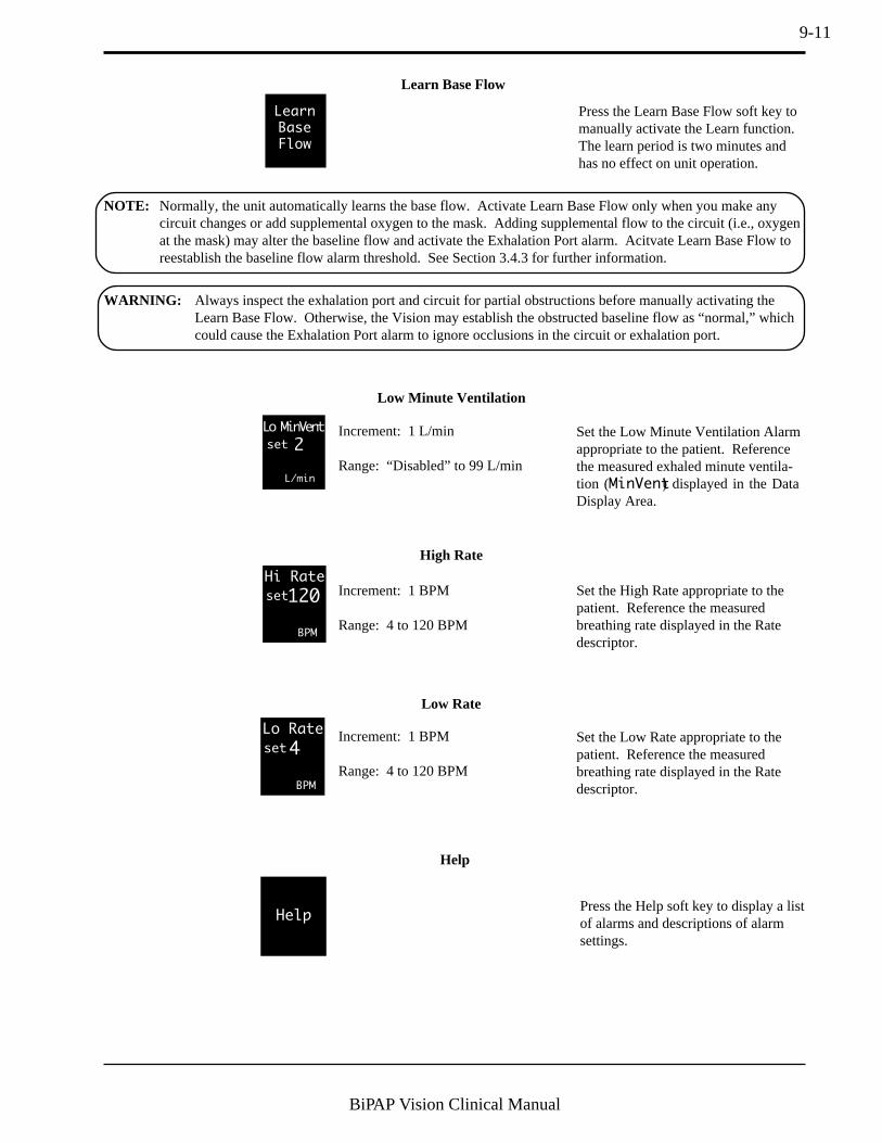
9-11
BiPAP Vision Clinical Manual
Low Minute Ventilation
Increment: 1 L/min
Range: “Disabled” to 99 L/min
Increment: 1 BPM
Range: 4 to 120 BPM
High Rate
Increment: 1 BPM
Range: 4 to 120 BPM
Low Rate
Lo MinVent
2
L/min
set
Hi Rate
120
BPM
set
Lo Rate
4
BPM
set
Set the Low Minute Ventilation Alarmappropriate to the patient. Referencethe measured exhaled minute ventila-tion (MinVent) displayed in the DataDisplay Area.
Set the High Rate appropriate to thepatient. Reference the measuredbreathing rate displayed in the Ratedescriptor.
Set the Low Rate appropriate to thepatient. Reference the measuredbreathing rate displayed in the Ratedescriptor.
Learn
Base
Flow
Learn Base Flow
Help
Help
Press the Help soft key to display a listof alarms and descriptions of alarmsettings.
Press the Learn Base Flow soft key tomanually activate the Learn function.The learn period is two minutes andhas no effect on unit operation.
NOTE: Normally, the unit automatically learns the base flow. Activate Learn Base Flow only when you make anycircuit changes or add supplemental oxygen to the mask. Adding supplemental flow to the circuit (i.e., oxygenat the mask) may alter the baseline flow and activate the Exhalation Port alarm. Acitvate Learn Base Flow toreestablish the baseline flow alarm threshold. See Section 3.4.3 for further information.
WARNING: Always inspect the exhalation port and circuit for partial obstructions before manually activating theLearn Base Flow. Otherwise, the Vision may establish the obstructed baseline flow as “normal,” whichcould cause the Exhalation Port alarm to ignore occlusions in the circuit or exhalation port.

9-12
BiPAP Vision Clinical Manual
STEP 4 When all alarms are set as desired, press the MONITORING key toreturn to the Monitoring screen.
MODE: S/T MODIFY
ALARMS
Hi P
30
cm H2O
VT 700 ml PIP 8 cm H2OMinVent 14 L/min
Ti/Ttot 15 % Pt. Trig 5 %Pt. Leak 1 L/min
Lo P
cm H2O
set
Lo P Delay
Learn
Base
Flow
16
sec
set
Apnea
Help
Disabled
sec
set
Hi Rate
80
BPM
set
Lo MinVent
20set
L/minP (cm H2O)
Vol (ml)
Flow (L/min)
Lo Rate
5
BPM
set
NOTE: If no user interaction occurs for a 3-minute time span, the unit defaults to the Monitoring screen.
MODE: S/T MONITORINGIPAP
15
cm H2O
cm H2O
EPAP
6
Rate
Options
Standby
12
BPM
%O2
55
%
VT 1000 ml PIP 15 cm H2OMinVent 14 L/min
P (cm H2O)
Vol (ml)
Flow (L/min)
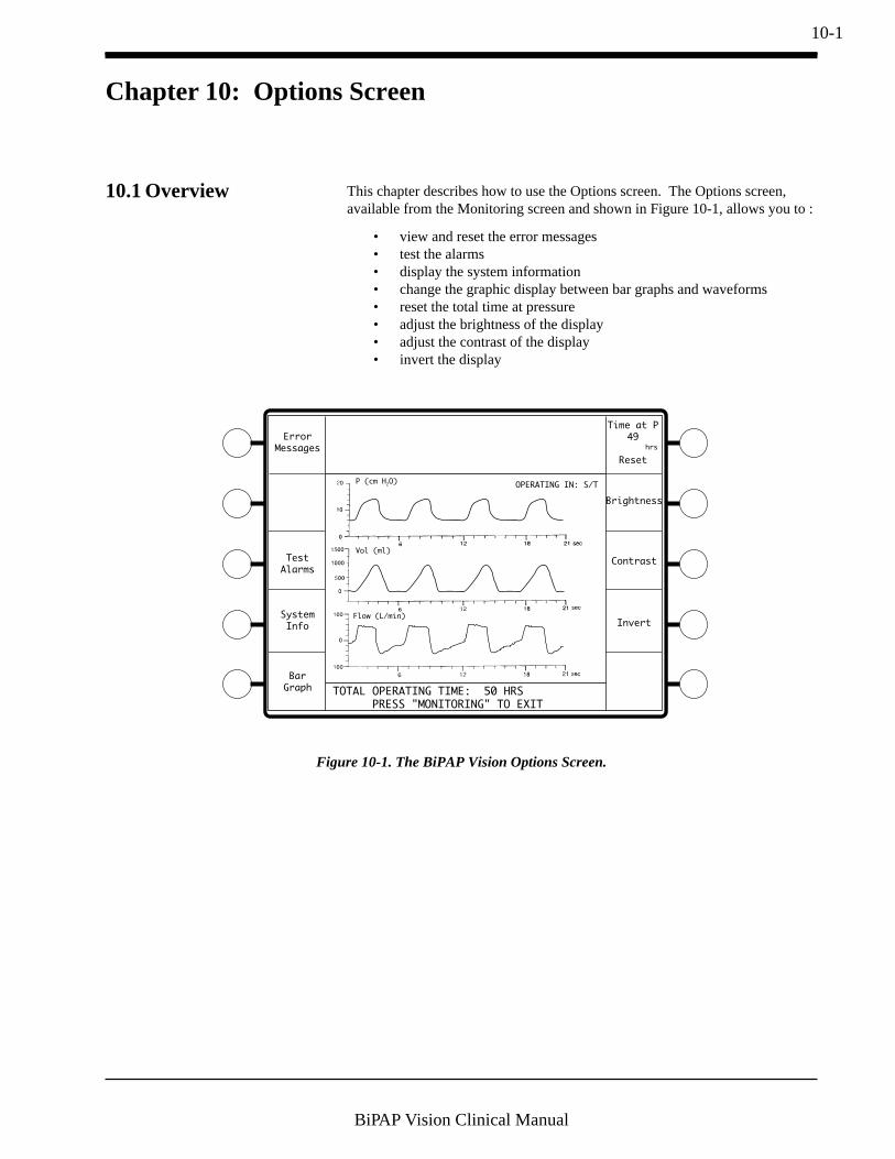
10-1
BiPAP Vision Clinical Manual
Chapter 10: Options Screen
10.1 Overview This chapter describes how to use the Options screen. The Options screen,available from the Monitoring screen and shown in Figure 10-1, allows you to :
• view and reset the error messages• test the alarms• display the system information• change the graphic display between bar graphs and waveforms• reset the total time at pressure• adjust the brightness of the display• adjust the contrast of the display• invert the display
P (cm H2O)
Vol (ml)
Flow (L/min)
OPERATING IN: S/T
TOTAL OPERATING TIME: 50 HRS
PRESS "MONITORING" TO EXIT
Error
Messages
Time at P
49
Reset
Test
Alarms
System
Info
Bar
Graph
Brightness
Contrast
Invert
hrs
Figure 10-1. The BiPAP Vision Options Screen.

10-2
BiPAP Vision Clinical Manual
10.2 Using the Options Screen
MODE: S/T MONITORINGIPAP
15
cm H2O
cm H2O
EPAP
6
Rate
Options
Standby
12
BPM
%O2
%
VT 1000 ml PIP 15 cm H2OMinVent 14 L/min
PS = 9 cm H2OP (cm H
2O)
Vol (ml)
Flow (L/min)
55set
— Press the Options soft key in the Monitoring screen.
P (cm H2O)
Vol (ml)
Flow (L/min)
OPERATING IN: S/T
TOTAL OPERATING TIME: 50 HRS
PRESS "MONITORING" TO EXIT
Error
Messages
Time at P
49
Reset
Test
Alarms
System
Info
Bar
Graph
Brightness
Contrast
Invert
hrs
The Options screen is displayed.
You may select:
• Error Messages• Test Alarms• System Info• Bar Graph
10.2.1 ERROR MESSAGES
Error messages are displayed in theMode/Message Area for reference tothe Service Manual.
When the errors have beencorrected, clear the message bypressing the Clear Error Messages softkey.
P (cm H2O)
Vol (ml)
Flow (L/min)
OPERATING IN: S/T
TOTAL OPERATING TIME: 50 HRS
PRESS "MONITORING" TO EXIT
Error
Messages
Time at P
49
Reset
Test
Alarms
Brightness
Contrast
Invert
hrs
System
Info
Bar
Graph
The Check Ventilator condition stores an error message in the Error Messagescreen. The error message history is helpful for troubleshooting the Visionventilator and should be checked by the biomedical personnel before contactingan authorized service center or the manufacturer.
P (cm H2O)
Vol (ml)
Flow (L/min)
OPERATING IN: S/T
TOTAL OPERATING TIME: 50 HRS
PRESS "MONITORING" TO EXIT
Error
Messages
Errors: 100 101 202
MCS: NONE
PAS: NONE
DCS: NONE
Clear
Error
Messages
Time at P
49
Reset
Test
Alarms
Brightness
Contrast
Invert
hrs
System
Info
Bar
Graph
NOTE: Repairs should be performedby authorized service personnel only.
• Time at PressureReset
• Brightness• Contrast• Invert

10-3
BiPAP Vision Clinical Manual
10.2.2 TESTING THE ALARMS
P (cm H2O)
Vol (ml)
Flow (L/min)
OPERATING IN: S/T
TOTAL OPERATING TIME: 50 HRS
PRESS "MONITORING" TO EXIT
Error
Messages
Time at P
49
Reset
Test
Alarms
System
Info
Bar
Graph
Brightness
Contrast
Invert
hrs
— Press the Test Alarms soft key.
ALARM
O2 Flow
Lo MinVent
Hi Rate
Lo Rate
Hi P
Lo P
Apnea
ProxLine Disc
Exh. Port
P Regulation
Disconnect
All alarm messages are displayed in the Mode/Message area, the Ventilator Inoperative andCheck Ventilator indicators activate, and theaudible alarm sounds.
The Vision unit allows you to test all of the audible and visual alarm indicators.The Test Alarms Control activates a solid audible tone and visual alarms for aminimum of 4 seconds.
NOTE: The alarms should be listed in the Mode/Message Area as shown above. If either the visual or audible alarmsfail to operate, discontinue using the unit and refer it for service.
NOTE: For details on each alarm function, see Chapter 12, Alarms and Troubleshooting.
NOTE: The Alarm Test should beperformed before each new setup.Refer to Chapter 7, PerformanceVerification.

10-4
BiPAP Vision Clinical Manual
10.2.3 DISPLAYING SYSTEM
I NFORMATION
System Information provides the following information:
• The installed software version• Verifies the installation of the oxygen module• The alarm package that is installed.
P (cm H2O)
Vol (ml)
Flow (L/min)
OPERATING IN: S/T
TOTAL OPERATING TIME: 50 HRS
PRESS "MONITORING" TO EXIT
Error
Messages
Time at P
49
Reset
Test
Alarms
System
Info
Bar
Graph
Brightness
Contrast
Invert
hrs
— Press the System Info soft key.
1. Software Version: 9.4
2. Oxygen Module: Yes
3. Alarm Module: Standard Alarms
1. Software Version: 9.4
2. Oxygen Module: Yes
3. Alarm Module: Standard Alarms
Error
Messages
Time at P
49
Reset
Test
Alarms
System
Info
Brightness
Contrast
Invert
hrs
The display lists the system information.
NOTE: A “NO” response in the Oxygen Module line maymean that the module is not functional.
The Alarm Module line will display “Optional AlarmModule” if the optional alarm module is installed.
10.2.4 CHANGING THE GRAPHIC
DISPLAY
You may choose to display the Pressure, Volume, and Flow as waveforms or asbar graphs.
P (cm H2O)
Vol (ml)
Flow (L/min)
OPERATING IN: S/T
TOTAL OPERATING TIME: 50 HRS
PRESS "MONITORING" TO EXIT
Error
Messages
Time at P
49
Reset
Test
Alarms
System
Info
Bar
Graph
Brightness
Contrast
Invert
hrs
P Vol Flow
0
4
8
12
16
20
0
300
600
900
1200
1500
-100
0
-66
-33
33
66
100 (cm H2
O) (ml) (L/min)
OPERATING IN: S/T
TOTAL OPERATING TIME: 50 HRS
PRESS "MONITORING" TO EXIT
Error
Messages
Time at P
49
Reset
Test
Alarms
System
Info
Waveform
Brightness
Contrast
Invert
hrs
— Press the Bar Graph soft key.
The Pressure, Volume, and Flow data are displayed as bargraphs. The Bar Graph soft key Descriptor changes to“Waveform”.
To return to the waveforms, press the Waveform soft key.
NOTE: In the U.S., the “optional”alarm package is installed in all Visionmodels.
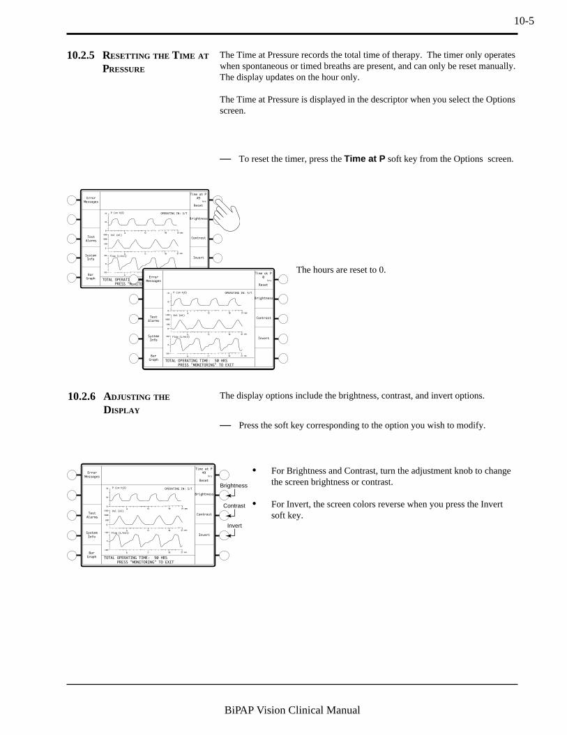
10-5
BiPAP Vision Clinical Manual
10.2.6 ADJUSTING THE
DISPLAY
— Press the soft key corresponding to the option you wish to modify.
P (cm H2O)
Vol (ml)
Flow (L/min)
OPERATING IN: S/T
TOTAL OPERATING TIME: 50 HRS
PRESS "MONITORING" TO EXIT
Error
Messages
Time at P
49
Reset
Test
Alarms
Brightness
Contrast
Invert
hrs
Brightness
Contrast
InvertSystem
Info
Bar
Graph
The display options include the brightness, contrast, and invert options.
• For Brightness and Contrast, turn the adjustment knob to changethe screen brightness or contrast.
• For Invert, the screen colors reverse when you press the Invertsoft key.
10.2.5 RESETTING THE TIME AT
PRESSURE
— To reset the timer, press the Time at P soft key from the Options screen.
The hours are reset to 0.
P (cm H2O)
Vol (ml)
Flow (L/min)
OPERATING IN: S/T
TOTAL OPERATING TIME: 50 HRS
PRESS "MONITORING" TO EXIT
Error
Messages
Time at P
49
Reset
Test
Alarms
Brightness
Contrast
Invert
hrs
System
Info
Bar
Graph
The Time at Pressure records the total time of therapy. The timer only operateswhen spontaneous or timed breaths are present, and can only be reset manually.The display updates on the hour only.
The Time at Pressure is displayed in the descriptor when you select the Optionsscreen.
P (cm H2O)
Vol (ml)
Flow (L/min)
OPERATING IN: S/T
TOTAL OPERATING TIME: 50 HRS
PRESS "MONITORING" TO EXIT
Error
Messages
Time at P
0
Reset
Test
Alarms
Brightness
Contrast
Invert
hrs
System
Info
Bar
Graph
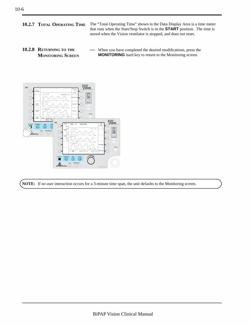
10-6
BiPAP Vision Clinical Manual
10.2.8 RETURNING TO THE
M ONITORING SCREEN
— When you have completed the desired modifications, press theMONITORING hard key to return to the Monitoring screen.
P (cm H2O)
Vol (ml)
Flow (L/min)
OPERATING IN: S/T
TOTAL OPERATING TIME: 50 HRS
PRESS "MONITORING" TO EXIT
Error
Messages
Time at P
49
Reset
Test
Alarms
Brightness
Contrast
Invert
hrs
System
Info
Bar
Graph
MODE: S/T MONITORINGIPAP
15
cm H2O
cm H2O
EPAP
6
Rate
Options
Standby
12
BPM
%O2
%
VT 1000 ml PIP 15 cm H2OMinVent 14 L/min
PS = 9 cm H2OP (cm H2O)
Vol (ml)
Flow (L/min)
55set
10.2.7 TOTAL OPERATING TIME The “Total Operating Time” shown in the Data Display Area is a time meterthat runs when the Start/Stop Switch is in the START position. The time isstored when the Vision ventilator is stopped, and does not reset.
NOTE: If no user interaction occurs for a 3-minute time span, the unit defaults to the Monitoring screen.

11-1
BiPAP Vision Clinical Manual
Chapter 11: Modifying Graphic Displays
11.1 Overview The Vision unit provides real-time Pressure, Volume, and Flow graphics on allscreens. The graphics can be displayed as waveforms or as bar graphs. SeeChapter 10 for instructions to change the graph type. Figure 11-1 illustrates thewaveform graphics. Figure 11-2 illustrates the bar graphics.
This chapter describes the methods of modifying the Pressure, Volume, Flow,and Time scales. It also describes how to freeze and unfreeze the graphics.
MODE: S/T MONITORINGIPAP
15
cm H2O
EPAP
6
cm H2O
Rate
Options
12
BPM
%O2
%
VT 700 ml PIP 15 cm H2OMinVent 14 L/min
PressureWaveform
VolumeWaveform
FlowWaveform
PS = 9 cm H2OP (cm H2O)
Vol (ml)
Flow (L/min)
55set
Figure 11-1. Real-time Waveforms.
MODE: S/T MONITORINGIPAP
15
cm H2O
cm H2O
EPAP
6
Rate
Options
12
BPM
%O2
%
VT 1000 ml PIP 15 cm H2OMinVent 14 L/min
PS = 9 cm H2O
PressureBar
VolumeBar
FlowBar
55set
P Vol Flow
0
4
8
12
16
20
0
300
600
900
1200
1500
-100
0
-66
-33
33
66
100 (cm H2
O) (ml) (L/min)
Figure 11-2. Real-time Bar Graphs.
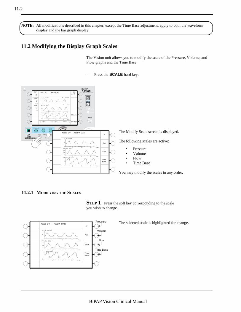
11-2
BiPAP Vision Clinical Manual
11.2 Modifying the Display Graph Scales
— Press the SCALE hard key.
STEP 1 Press the soft key corresponding to the scaleyou wish to change.
MODE: S/T MONITORINGIPAP
15
cm H2O
cm H2O
EPAP
6
Rate
Options
Standby
12
BPM
%O2
%
VT 1000 ml PIP 15 cm H2OMinVent 14 L/min
PS = 9 cm H2OP (cm H2O)
Vol (ml)
Flow (L/min)
55set
The Modify Scale screen is displayed.
The following scales are active:
• Pressure• Volume• Flow• Time Base
You may modify the scales in any order.
8
8
P (cm H2O)
Vol (ml)
Flow (L/min)
MODE: S/T MODIFY SCALE
P
Vol
Flow
Time
Base
8
8
P (cm H2O)
Vol (ml)
Flow (L/min)
MODE: S/T MODIFY SCALE
P
Vol
Flow
Time
Base
Pressure
Volume
Flow
Time Base
The selected scale is highlighted for change.
The Vision unit allows you to modify the scale of the Pressure, Volume, andFlow graphs and the Time Base.
11.2.1 MODIFYING THE SCALES
NOTE: All modifications described in this chapter, except the Time Base adjustment, apply to both the waveformdisplay and the bar graph display.

11-3
BiPAP Vision Clinical Manual
Increment: 5 cm H2O
Full Scale Range: 0 cm H2O to50 cm H2O
P (cm H2O)
20
0
40
Pressure Scale
Volume Scale
Vol (ml)
Increment: 500 ml
Full Scale Range: 0 ml to4000 ml
50
- 50
0
Flow (L/min) Increment: 50 L/min
Full Scale Range: -300 L/min to+300 L/min
Flow Scale
STEP 2 Turn the adjustment knob as needed.
Flow (L/min)
15
Increment: 3 seconds
Full Scale Range: 3 sec to 24 sec
Time Base
NOTE: The Time Base adjustmentsimultaneously adjusts the time basescale of all waveforms.
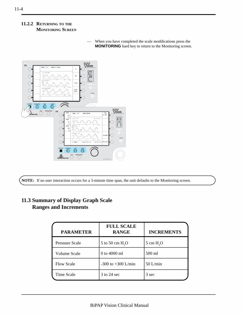
11-4
BiPAP Vision Clinical Manual
11.3 Summary of Display Graph ScaleRanges and Increments
11.2.2 RETURNING TO THE
M ONITORING SCREEN
— When you have completed the scale modifications press theMONITORING hard key to return to the Monitoring screen.
8
8
MODE: S/T MODIFY SCALE
P
Vol
Flow
Time
Base
P (cm H2O)
Vol (ml)
Flow (L/min)
MODE: S/T MONITORINGIPAP
15
cm H2O
cm H2O
EPAP
6
Rate
Options
Standby
12
BPM
%O2
%
VT 1000 ml PIP 15 cm H2OMinVent 14 L/min
PS = 9 cm H2O
Vol (ml)
P (cm H2O)
Flow (L/min)
55set
NOTE: If no user interaction occurs for a 3-minute time span, the unit defaults to the Monitoring screen.
PARAMETER
Pressure Scale
Volume Scale
Flow Scale
Time Scale
FULL SCALERANGE
5 to 50 cm H2O
0 to 4000 ml
-300 to +300 L/min
3 to 24 sec
INCREMENTS
5 cm H2O
500 ml
50 L/min
3 sec

11-5
BiPAP Vision Clinical Manual
11.4 Freezing and Unfreezing the Graphs
The graphs stop scrolling but the Data Display Arearemains active and continues to update with each breath.
When the Freeze graph is active, the message “FREEZEACTIVE” appears in the Mode/Message Area.
• To unfreeze the graphs, press the FREEZE/UNFREEZE key a secondtime. The graphs resume scrolling. The screen is erased and starts a newscroll from the left.
• Press the FREEZE/UNFREEZE hard key.
MODE: S/T MONITORINGIPAP
15
cm H2O
cm H2O
EPAP
6
Rate
Options
12
BPM
%O2
%
VT 1000 ml PIP 15 cm H2OMinVent 14 L/min
PS = 9 cm H2O
Vol (ml)
P (cm H2O)
Flow (L/min)
FREEZE ACTIVE55set

11-6
BiPAP Vision Clinical Manual

12-1
BiPAP Vision Clinical Manual
Chapter 12: Alarms and Troubleshooting
12.1 Alarms Overview This chapter describes the alarm parameters, how to troubleshoot alarmconditions, and how to troubleshoot mask problems.
The Vision unit contains two types of alarms: System and Adjustable. SystemAlarms are integral to the Vision unit to check system operations such as ACpower and internal alarm battery. System Alarms are not adjustable.
Adjustable Alarms are used to monitor patient parameters, such as highpressure and apnea. These alarms can be adjusted through the Modify Alarmsscreen.
The Vision ventilator may be connected from the Nurse Call/Remote Alarmconnector to most hospital call and alarm systems. You must verify whether theinstitution’s system is a Normally OPEN or Normally CLOSED circuit. ANormally OPEN system refers to an alarm system that detects an open circuit innormal conditions and a closed circuit during alarm conditions. A NormallyCLOSED system detects a closed circuit in normal circumstances and an opencircuit during alarm conditions. The Vision unit is manufactured with aNormally OPEN configuration. The Vision unit may be changed to interfacewith either system. Refer to the BiPAP Vision Service Manual for details.
WARNING: For the following reasons, attention by qualified medical personnel is required whenever a patient isattached to a ventilator:
a. Some malfunctions require immediate corrective action.
b. No monitor, or any combination of monitors, can give absolute assurance of warning in the event ofany and every form of malfunction of the ventilator or gas delivery system. A trained caregiver shouldbe able to respond in a timely manner to alarm conditions. The attention level required when a patient isattached to an assist ventilator must be determined by the physician based on the requirements of thepatient.
WARNING: The Adjustable Alarm settings should be reevaluated whenever a change in settings is made on theventilator.
NOTE: The alarm test should be performed before using the ventilator, and should be verified daily. Verify that boththe audible and visual alarm indicators are active during the alarm test. If either component is not active, havethe ventilator serviced.

12-2
BiPAP Vision Clinical Manual
12.1.1 ALARM INDICATIONS
P (cm H2O)
Vol (ml)
Flow (L/min)
OPERATING IN: S/T
Hi P
IPAP
15
cm H2O
cm H2O
EPAP
6
Rate
Options
Standby
12
BPM
%O2
VT 1000 ml PIP 15 cm H2OMinVent 14 L/min
ALARM
Flashing"ALARM"
Visualalarm
indication
55set
Figure 12-1. Alarm Indications.
12.1.2 ALARM SILENCE AND
RESET
The audible indicator of most alarms is self-cancellable if the alarm condition iscorrected. The Alarm Silence hard key turns off the audible alarm for twominutes. Any further pressing of the Alarm Silence hard key has no effect onthe alarm. When the alarm silence is active, the message “Alarm Silenced”appears in the Mode/Message Area for the duration of the silence period. Anynew alarm conditions, except Apnea and Vent Inop, that occur during thesilence period will provide a visual alert, but will not trigger the audible alarm.
The visual indicator in the Mode/Message Area is cancelled only when theAlarm Reset hard key is pressed. The Alarm Reset hard key cancels the alarmsilence period and resets the visual indicators and alarm logic. The alarmimmediately reactivates if the condition causing the alarm has not beencorrected.
The Nurse Call/Remote Alarm feature self-cancels if the alarm condition iscorrected. The Alarm Silence key turns off the Nurse Call/Remote Alarmfeature for two minutes.
All alarms contain an audible and visual element. In the event of an alarmcondition, the audible alarm sounds and the screen changes to show the alarmcondition in the Mode/Message Area. See Figure 12-1. The audible element isdescribed in Section 12.2 for each type of alarm condition.
NOTE: During an alarm condition,items that are accessed with theOptions soft key and that use theMode/Message area for display areinaccessible. The displays areautomatically returned when thealarm condition is cleared and reset.
NOTE: The Apnea and VentilatorInoperative alarms override the silenceperiod and trigger both a visual andaudible alarm.
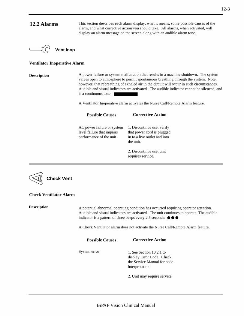
12-3
BiPAP Vision Clinical Manual
Corrective ActionPossible Causes
AC power failure or systemlevel failure that impairsperformance of the unit
1. Discontinue use; verifythat power cord is pluggedin to a live outlet and intothe unit.
2. Discontinue use; unitrequires service.
This section describes each alarm display, what it means, some possible causes of thealarm, and what corrective action you should take. All alarms, when activated, willdisplay an alarm message on the screen along with an audible alarm tone.
12.2 Alarms
Check Vent
Vent Inop
Ventilator Inoperative Alarm
Description
Check Ventilator Alarm
1. See Section 10.2.1 todisplay Error Code. Checkthe Service Manual for codeinterpretation.
2. Unit may require service.
System error
Corrective ActionPossible Causes
Description
A power failure or system malfunction that results in a machine shutdown. The systemvalves open to atmosphere to permit spontaneous breathing through the system. Note,however, that rebreathing of exhaled air in the circuit will occur in such circumstances.Audible and visual indicators are activated. The audible indicator cannot be silenced, andis a continuous tone:
A Ventilator Inoperative alarm activates the Nurse Call/Remote Alarm feature.
A potential abnormal operating condition has occurred requiring operator attention.Audible and visual indicators are activated. The unit continues to operate. The audibleindicator is a pattern of three beeps every 2.5 seconds:
A Check Ventilator alarm does not activate the Nurse Call/Remote Alarm feature.
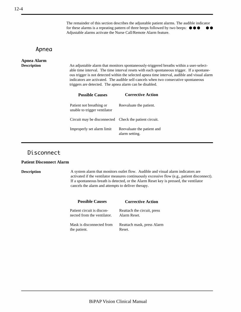
12-4
BiPAP Vision Clinical Manual
Corrective ActionPossible Causes
Disconnect
Patient not breathing orunable to trigger ventilator
Circuit may be disconnected
Improperly set alarm limit
Reevaluate the patient.
Check the patient circuit.
Reevaluate the patient andalarm setting.
Apnea
Apnea AlarmAn adjustable alarm that monitors spontaneously-triggered breaths within a user-select-able time interval. The time interval resets with each spontaneous trigger. If a spontane-ous trigger is not detected within the selected apnea time interval, audible and visual alarmindicators are activated. The audible self-cancels when two consecutive spontaneoustriggers are detected. The apnea alarm can be disabled.
Patient Disconnect Alarm
A system alarm that monitors outlet flow. Audible and visual alarm indicators areactivated if the ventilator measures continuously excessive flow (e.g., patient disconnect).If a spontaneous breath is detected, or the Alarm Reset key is pressed, the ventilatorcancels the alarm and attempts to deliver therapy.
Patient circuit is discon-nected from the ventilator.
Mask is disconnected fromthe patient.
Reattach the circuit, pressAlarm Reset.
Reattach mask, press AlarmReset.
Description
Description
Corrective ActionPossible Causes
The remainder of this section describes the adjustable patient alarms. The audible indicatorfor these alarms is a repeating pattern of three beeps followed by two beeps:Adjustable alarms activate the Nurse Call/Remote Alarm feature.
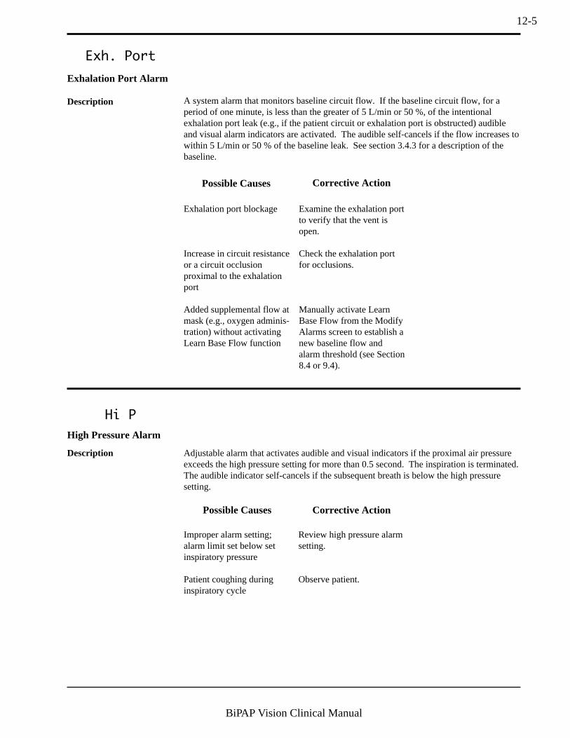
12-5
BiPAP Vision Clinical Manual
Exh. Port
Exhalation Port Alarm
A system alarm that monitors baseline circuit flow. If the baseline circuit flow, for aperiod of one minute, is less than the greater of 5 L/min or 50 %, of the intentionalexhalation port leak (e.g., if the patient circuit or exhalation port is obstructed) audibleand visual alarm indicators are activated. The audible self-cancels if the flow increases towithin 5 L/min or 50 % of the baseline leak. See section 3.4.3 for a description of thebaseline.
Exhalation port blockage
Increase in circuit resistanceor a circuit occlusionproximal to the exhalationport
Added supplemental flow atmask (e.g., oxygen adminis-tration) without activatingLearn Base Flow function
Examine the exhalation portto verify that the vent isopen.
Check the exhalation portfor occlusions.
Manually activate LearnBase Flow from the ModifyAlarms screen to establish anew baseline flow andalarm threshold (see Section8.4 or 9.4).
Description
Corrective ActionPossible Causes
Hi P
Improper alarm setting;alarm limit set below setinspiratory pressure
Patient coughing duringinspiratory cycle
Review high pressure alarmsetting.
Observe patient.
High Pressure Alarm
Description Adjustable alarm that activates audible and visual indicators if the proximal air pressureexceeds the high pressure setting for more than 0.5 second. The inspiration is terminated.The audible indicator self-cancels if the subsequent breath is below the high pressuresetting.
Corrective ActionPossible Causes
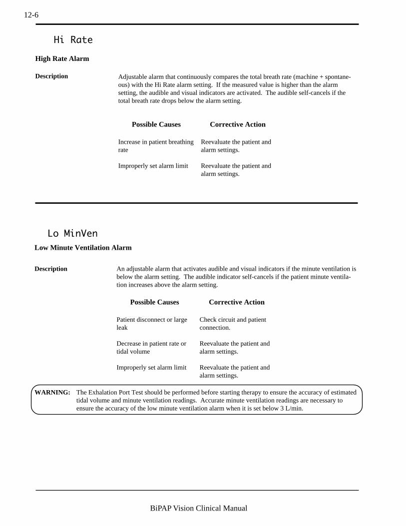
12-6
BiPAP Vision Clinical Manual
Lo MinVen
Low Minute Ventilation Alarm
Description An adjustable alarm that activates audible and visual indicators if the minute ventilation isbelow the alarm setting. The audible indicator self-cancels if the patient minute ventila-tion increases above the alarm setting.
Patient disconnect or largeleak
Decrease in patient rate ortidal volume
Improperly set alarm limit
Check circuit and patientconnection.
Reevaluate the patient andalarm settings.
Reevaluate the patient andalarm settings.
Corrective ActionPossible Causes
WARNING: The Exhalation Port Test should be performed before starting therapy to ensure the accuracy of estimatedtidal volume and minute ventilation readings. Accurate minute ventilation readings are necessary toensure the accuracy of the low minute ventilation alarm when it is set below 3 L/min.
Hi Rate
High Rate Alarm
Description Adjustable alarm that continuously compares the total breath rate (machine + spontane-ous) with the Hi Rate alarm setting. If the measured value is higher than the alarmsetting, the audible and visual indicators are activated. The audible self-cancels if thetotal breath rate drops below the alarm setting.
Increase in patient breathingrate
Improperly set alarm limit
Reevaluate the patient andalarm settings.
Reevaluate the patient andalarm settings.
Corrective ActionPossible Causes
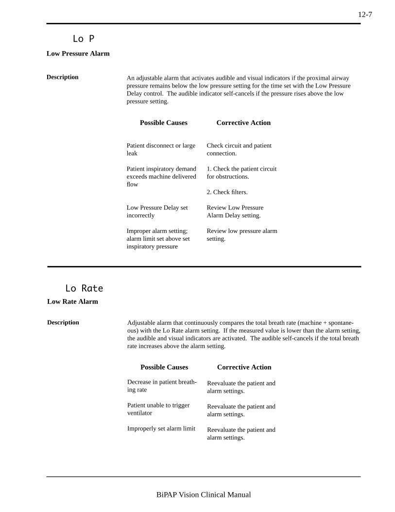
12-7
BiPAP Vision Clinical Manual
Lo P
Patient disconnect or largeleak
Patient inspiratory demandexceeds machine deliveredflow
Low Pressure Delay setincorrectly
Improper alarm setting;alarm limit set above setinspiratory pressure
Check circuit and patientconnection.
1. Check the patient circuitfor obstructions.
2. Check filters.
Review Low PressureAlarm Delay setting.
Review low pressure alarmsetting.
Low Pressure Alarm
Description An adjustable alarm that activates audible and visual indicators if the proximal airwaypressure remains below the low pressure setting for the time set with the Low PressureDelay control. The audible indicator self-cancels if the pressure rises above the lowpressure setting.
Corrective ActionPossible Causes
Lo Rate
Low Rate Alarm
Description Adjustable alarm that continuously compares the total breath rate (machine + spontane-ous) with the Lo Rate alarm setting. If the measured value is lower than the alarm setting,the audible and visual indicators are activated. The audible self-cancels if the total breathrate increases above the alarm setting.
Decrease in patient breath-ing rate
Patient unable to triggerventilator
Improperly set alarm limit
Reevaluate the patient andalarm settings.
Reevaluate the patient andalarm settings.
Reevaluate the patient andalarm settings.
Corrective ActionPossible Causes
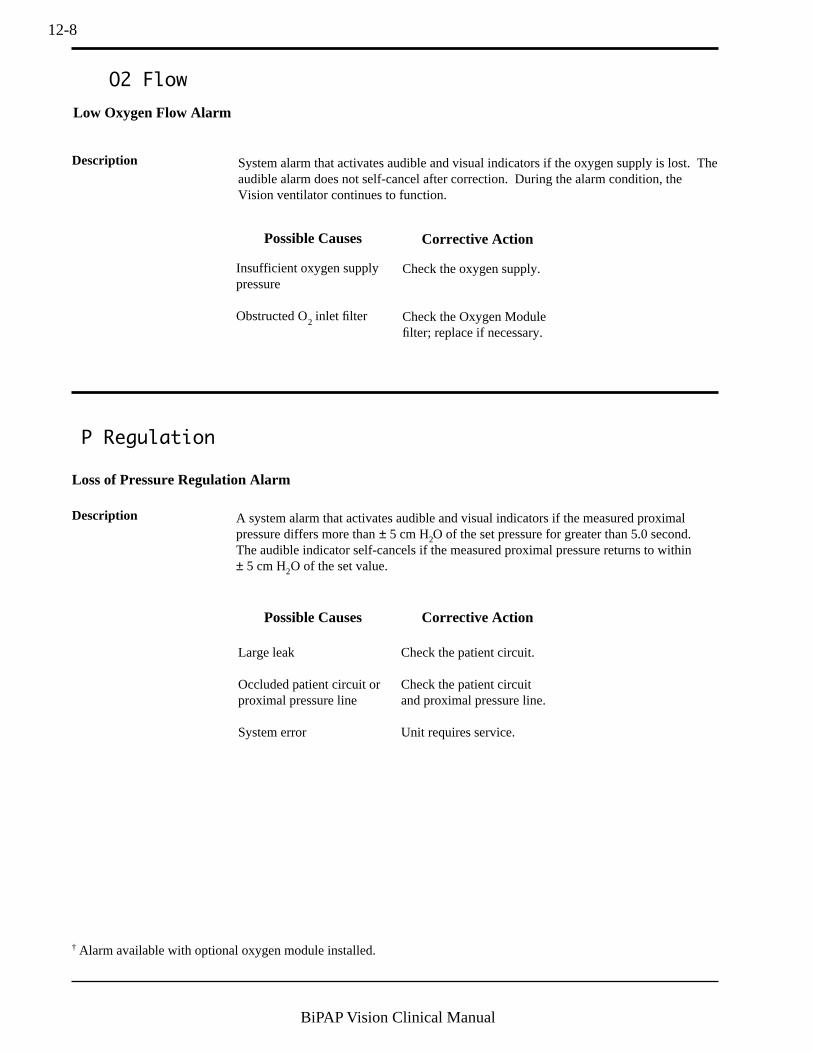
12-8
BiPAP Vision Clinical Manual
Corrective ActionPossible Causes
P Regulation
Loss of Pressure Regulation Alarm
Description A system alarm that activates audible and visual indicators if the measured proximalpressure differs more than ± 5 cm H2O of the set pressure for greater than 5.0 second.The audible indicator self-cancels if the measured proximal pressure returns to within± 5 cm H2O of the set value.
Large leak
Occluded patient circuit orproximal pressure line
System error
Check the patient circuit.
Check the patient circuitand proximal pressure line.
Unit requires service.
O2 Flow
Insufficient oxygen supplypressure
Obstructed O2 inlet filter
Check the oxygen supply.
Check the Oxygen Modulefilter; replace if necessary.
Low Oxygen Flow Alarm
Description System alarm that activates audible and visual indicators if the oxygen supply is lost. Theaudible alarm does not self-cancel after correction. During the alarm condition, theVision ventilator continues to function.
Corrective ActionPossible Causes
† Alarm available with optional oxygen module installed.

12-9
BiPAP Vision Clinical Manual
ProxLine Disc
Proximal Pressure Line Disconnect Alarm
Description A system alarm that activates audible and visual indicators if the proximal pressuremeasures less than 1.0 cm H2O for greater than 1 second. The audible indicator self-cancels if the measured proximal pressure increases above 1.0 cm H2O. The alarm isautomatically disabled when the unit goes into flow limit control.
Proximal pressure linedisconnection or obstruction
Check the proximal pressureline.
Corrective ActionPossible Causes
WARNING: If an alarm condition cannot be corrected, discontinue use and refer the unit for service.
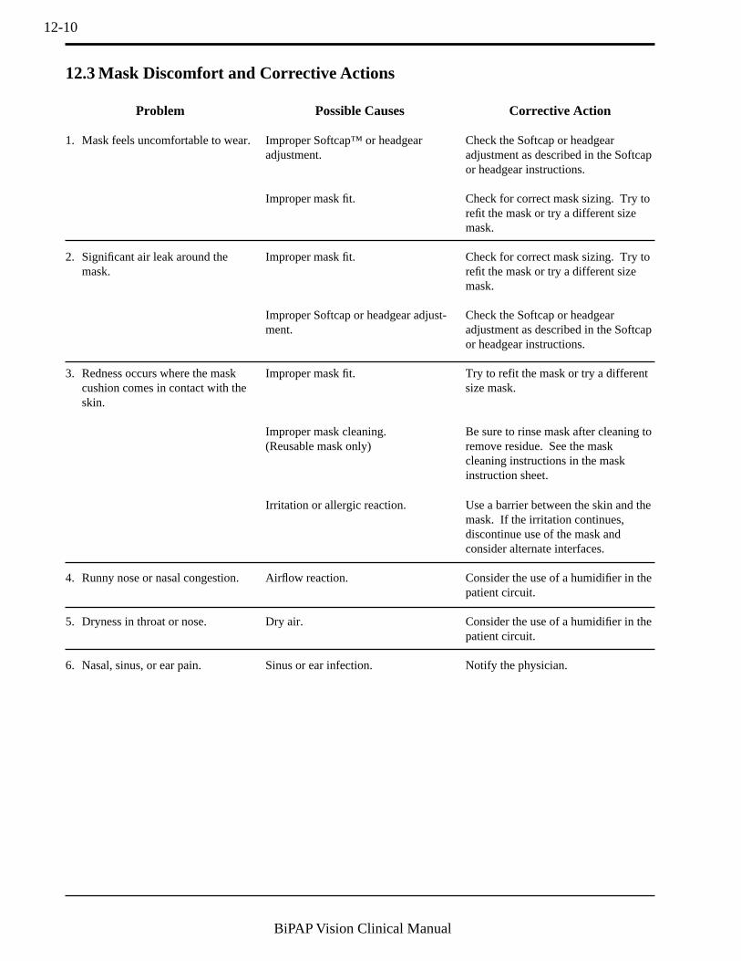
12-10
BiPAP Vision Clinical Manual
12.3 Mask Discomfort and Corrective Actions
Problem
1. Mask feels uncomfortable to wear.
2. Significant air leak around themask.
3. Redness occurs where the maskcushion comes in contact with theskin.
4. Runny nose or nasal congestion.
5. Dryness in throat or nose.
6. Nasal, sinus, or ear pain.
Possible Causes
Improper Softcap™ or headgearadjustment.
Improper mask fit.
Improper mask fit.
Improper Softcap or headgear adjust-ment.
Improper mask fit.
Improper mask cleaning.(Reusable mask only)
Irritation or allergic reaction.
Airflow reaction.
Dry air.
Sinus or ear infection.
Corrective Action
Check the Softcap or headgearadjustment as described in the Softcapor headgear instructions.
Check for correct mask sizing. Try torefit the mask or try a different sizemask.
Check for correct mask sizing. Try torefit the mask or try a different sizemask.
Check the Softcap or headgearadjustment as described in the Softcapor headgear instructions.
Try to refit the mask or try a differentsize mask.
Be sure to rinse mask after cleaning toremove residue. See the maskcleaning instructions in the maskinstruction sheet.
Use a barrier between the skin and themask. If the irritation continues,discontinue use of the mask andconsider alternate interfaces.
Consider the use of a humidifier in thepatient circuit.
Consider the use of a humidifier in thepatient circuit.
Notify the physician.

13-1
BiPAP Vision Clinical Manual
Chapter 13: Oxygen Delivery with the Vision Ventilator
13.1 Overview The Vision ventilator provides an Oxygen Module to deliver and controloxygen to the patient. The module provides control of oxygen concentrationfrom 21 percent to 100 percent with stable and reliable delivery of the concen-tration.
WARNING: Oxygen should be administered only on the order of a physician.
WARNING: Oxygen accelerates fires. Keep the Vision ventilator and the oxygen source away from heat, open flames,any oily substance, or other sources of ignition. DO NOT smoke in the area near the Vision ventilator orthe oxygen source.
WARNING: Supplemental oxygen should not be added to the breathing circuit by placing the source where the gaswill be entrained through the inlet filter on the rear of the unit.
WARNING: Never attach oxygen tubing or any positive pressure source to the Pressure Line Port on the front panel ofthe Vision ventilator.
WARNING: When administering supplemental oxygen by means other than the optional Oxygen Module, a controlledmethod of setting and measuring inspired oxygen concentrations cannot be accomplished. At a fixed flowrate of supplemental oxygen, the inspired oxygen concentration will vary, depending on the IPAP andEPAP settings, patient breathing pattern, and the leak rate. Substantial leaks around the mask may reducethe inspired oxygen concentration to less than the expected concentrations.
WARNING: Continuous patient monitoring is recommended while administering oxygen. Patient monitoring shouldconsist of, at a minimum, patient observation and pulse oximetry. Arterial blood gas measurementsshould be used when necessary.
WARNING: When the Oxygen Module is used in conjunction with the PAV/T mode, excessive patient pressure mayresult if you exceed the recommended inlet pressure of the oxygen module.
WARNING: When using oxygen with the Vision ventilator, the oxygen supply must comply with local regulations formedical oxygen.
NOTE: When the Oxygen Module is in use, the Vision ventilator will display the set oxygen concentration, which maynot be the actual oxygen concentration delivered to the patient. Respironics recommends the use of an externaloxygen analyzer added to the patient circuit to measure actual oxygen concentration. Continuous patientmonitoring should consist of, at a minimum, patient observation and pulse oximetry. Arterial blood gasmeasurement should be used when necessary.

13-2
BiPAP Vision Clinical Manual
115 VAC/60 Hz 230 VAC/50 Hz
Single Phase TBD
T Type
115 VAC - T 8 A - 1/4" x 1 1/4"
230 VAC - T 4 A - 5 x 20 mmTYPE BF
CLASS I
Warnings & Cautions
!
CAUTION:The voltage selection switch must be
set for the proper line voltage.
WARNING: For continued protection against risk
of fire, replace with the same type
and rating of fuse.
WARNING: Disconnect supply before servicing.
WARNING: DO NOT connect to an electrical
outlet controlled by a wall switch.
WARNING: This is an assist ventilator and is
intended to augment the ventilation
of a spontaneously breathing patient.
DANGER:Explosion Hazard. Do not use in the
presence of flammable anesthetics.IP22
CAUTION:U.S. federal law restricts the sale or
use of this device by or on the order
of a physician.
¤
Serial #
Warnings & Cautions
!
CAUTION:Do not operate with cover removed.
WARNING: Disconnect supply before servicing.
Recommended Oxygen Pressure Range:
35 to 100 psigCAUTION:
When servicing, use only approved
replacement parts.
WARNING: Do not exceed maximum working
pressure.
From O2Source
Standard OxygenConnector
¤
¤
1001 Mu r r y R i dge D r i v e
Murrysvi l le, Pennsylvania
15668 - 8550 U .S .A .Serial #
Serial # 23659#
When servicing, use only approved
replacement parts.
13.2 Oxygen Module The Respironics Oxygen Module is on the rear of the Vision ventilator. Themodule requires a high-pressure oxygen source for operation. Figure 13-1shows the Oxygen Module and the O2 supply connection.
Figure 13-1. Oxygen Supply Attachment.
MODE: S/T MONITORINGIPAP
15
cm H2O
cm H2O
EPAP
6
Rate
Options
Standby
12
BPM
%O2
%
VT 1000 ml PIP 15 cm H2OMinVent 14 L/min
PS = 9 cm H2O
%O2 Descriptor
P (cm H2O)
Vol (ml)
Flow (L/min)
55set
Figure 13-2. Oxygen Concentration Descriptor.
The Oxygen Module accepts a standard oxygen inlet connector from a medical-grade oxygen source. The source may range from 50 to 100 psig. An inlet filterin the Oxygen Module provides a collection efficiency of 100% for 40.0 micronand larger particles.
Note: The high pressure oxygen source must be capable of supplying the peakinspiratory oxygen flow based on the set oxygen concentration andpatient inspiratory flow.
When the module is installed, the %O2 Descriptor appears in the right columnas shown in Figure 13-2.

13-3
BiPAP Vision Clinical Manual
The Oxygen Module is recommended when oxygen delivery with the BiPAPVision System is needed. It regulates and proportions oxygen into the air fromthe blower according to the oxygen concentration level set on the Parametersscreen. The Vision % FiO2 (Fraction of inspired Oxygen) Setting Control iscalibrated at a nominal patient setting of 15 breaths per minute (BPM) and 500ml tidal volume. Under these conditions the delivered FiO2 is accurate to withinthe greater of ±3% FiO2 or ±10% of setting. The selectable concentration rangeis from 21% to 100%.
Because Vision does not have an internal blender, the clinician should expectsome change in delivered FiO2 with changes in respiratory settings or patientparameters. Actual delivered FiO2 concentration should be monitored, asappropriate to the patient’s condition.
Typical delivered FiO2 concentration can be estimated from the following table:
Respiratory Parameters Expected Delivered FiO2 vs. Setting
250 ml, 10 BPM up to 15% FiO2 higher than setting
250 ml, 20 BPM greater of ±3% FiO2 or ±10% of setting
250 ml, 30 BPM up to 10% FiO2 lower than setting
500 ml, 10 BPM greater of ±3% FiO2 or ±10% of setting
500 ml, 15 BPM greater of ±3% FiO2 or ±10% of setting
500 ml, 30 BPM up to 10% FiO2 lower than setting
800 ml, 10 BPM greater of ±3% FiO2 or ±10% of setting
800 ml, 20 BPM up to 10% FiO2 lower than setting
An “O2 Flow” Alarm is activated if the oxygen inlet supply is lost. See Chapter13 for further information concerning the alarm.
The oxygen concentration is set by pressing the %O2 Soft Key in the ChangeParameters screen, then turning the adjustment knob. See Chapters 8 and 9 fordetailed instructions for setting the concentration in the CPAP, S/T, and PAV/Tmodes. The set oxygen concentration is maintained between mode changes.
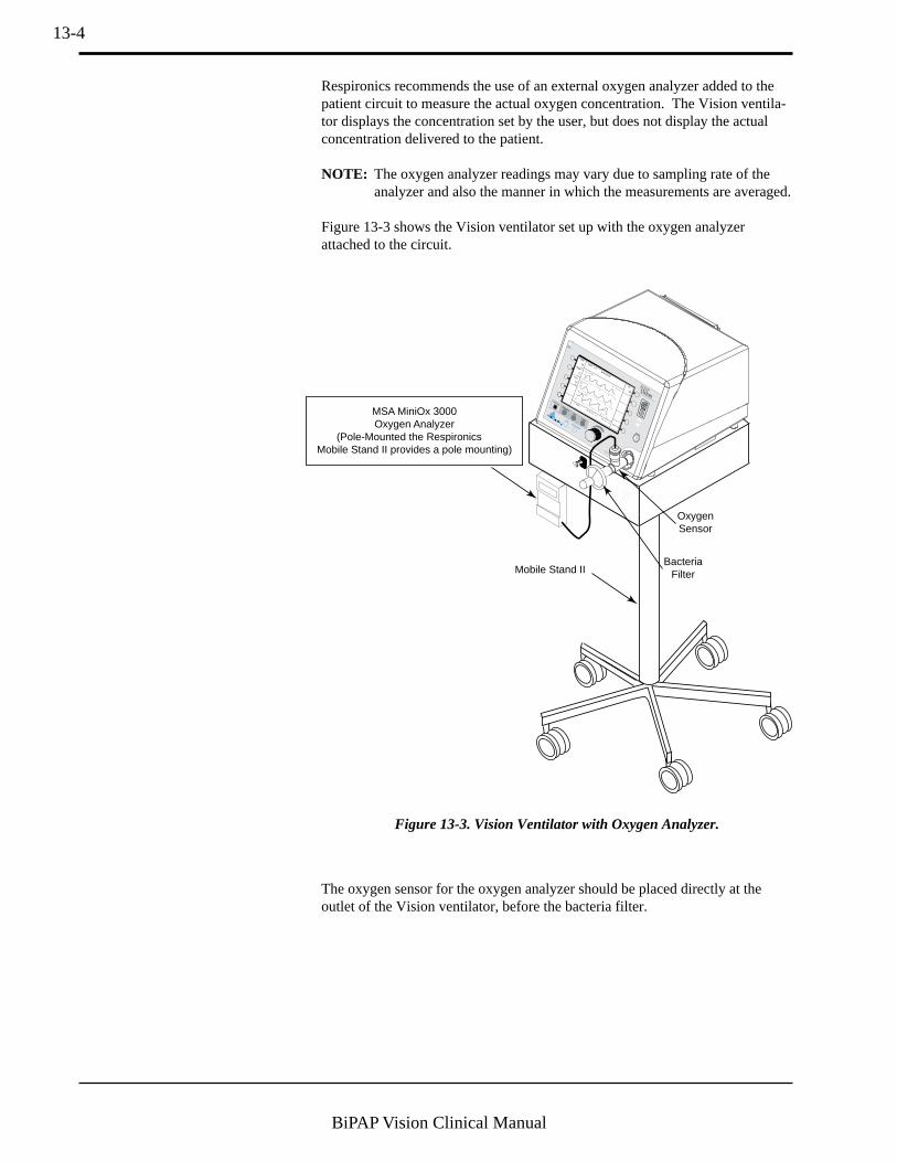
13-4
BiPAP Vision Clinical Manual
Respironics recommends the use of an external oxygen analyzer added to thepatient circuit to measure the actual oxygen concentration. The Vision ventila-tor displays the concentration set by the user, but does not display the actualconcentration delivered to the patient.
NOTE: The oxygen analyzer readings may vary due to sampling rate of theanalyzer and also the manner in which the measurements are averaged.
Figure 13-3 shows the Vision ventilator set up with the oxygen analyzerattached to the circuit.
MODE: S/T MONITORING
IPAP
15
cm H2O
cm H2O
EPAP
6
Rate
Options
12
BPM
%O2
55
%
VT 1000
ml
PIP 15 cm H
2O
MinVent 14 L/min
PS = 9 cm H2O
P (cm H2O)
Vol (ml)
Flow (L/min)
MSA MiniOx 3000Oxygen Analyzer
(Pole-Mounted the Respironics Mobile Stand II provides a pole mounting)
OxygenSensor
BacteriaFilterMobile Stand II
Figure 13-3. Vision Ventilator with Oxygen Analyzer.
The oxygen sensor for the oxygen analyzer should be placed directly at theoutlet of the Vision ventilator, before the bacteria filter.

14-1
BiPAP Vision Clinical Manual
Chapter 14: Cleaning and Routine Maintenance
CAUTION: Do not immerse the Vision unit in water or allow any liquid to enter the cabinet or the inlet filter.
STEP 1 Turn the Vision unit Start/Stop switch to the STOP position andunplug the electrical cord from the wall outlet and from the back ofthe unit.
CAUTION: A dirty inlet filter may cause high operating temperatures and may affect ventilator performance.Examine the inlet filter for integrity and cleanliness before each use. When the filter becomes dirty, itmust be replaced to ensure normal operation.
This chapter provides guidelines and illustrates the cleaning and routinemaintenance procedures. Refer to the BiPAP Vision Service Manual for therecommended maintenance schedule.
NOTE: The following guidelines for cleaning refer to the Vision unit only. Refer to the individual instructions forcleaning accessories.
14.3 Replacing theInlet Filter
14.1 Overview
14.2.1 CLEANING THE
FRONT PANEL
Clean the front panel as needed by wiping with water or 70% Isopropyl Alcoholonly.
14.2.2 CLEANING THE
ENCLOSURE
Clean the exterior of the enclosure as needed by wiping with any bacterial agentbut do not allow liquid to enter the inside of the ventilator.
14.2 Cleaning theVision Unit
WARNING: Before cleaning or performing any routine maintenance, always switch the Vision unit’s Start/Stopswitch to the STOP position and unplug the electrical cord from the wall outlet and from the rear ofthe unit.
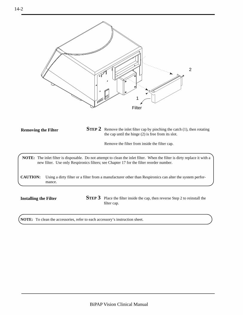
14-2
BiPAP Vision Clinical Manual
STEP 2 Remove the inlet filter cap by pinching the catch (1), then rotatingthe cap until the hinge (2) is free from its slot.
Remove the filter from inside the filter cap.
Removing the Filter
Installing the Filter
NOTE: To clean the accessories, refer to each accessory’s instruction sheet.
NOTE: The inlet filter is disposable. Do not attempt to clean the inlet filter. When the filter is dirty replace it with anew filter. Use only Respironics filters; see Chapter 17 for the filter reorder number.
1
2
Filter
CAUTION: Using a dirty filter or a filter from a manufacturer other than Respironics can alter the system perfor-mance.
STEP 3 Place the filter inside the cap, then reverse Step 2 to reinstall thefilter cap.

14-3
BiPAP Vision Clinical Manual
WARNING: Unplug the Vision unit before changing the fuses.
14.4 Changing theSystem Fuses
115V
120V
Pry DrawersHere
14.5 Voltage Selection The voltage selection is set at the factory. If you wish to use the Vision unitwith a different inlet voltage, contact your medical equipment supplier.
STEP 1 Unplug the AC power cord from the wall outlet and from thepower entry module on the rear of the Vision unit.
STEP 2 With a small, flat-bladed screwdriver, pry open the fuse holder doorfrom the top. The door hinges downward.
STEP 3 Pry the fuse drawers loose and slide them out of the power entrymodule.
STEP 4 Pull the fuses out of the fuse drawers.
STEP 5 Replace both fuses, even if only one needs to be changed.
STEP 6 Place the new fuses in the fuse drawers and slide the fuse drawersback into the power entry module with the arrows on the front of thedrawers pointing to the right.
STEP 7 Swing the fuse drawer door shut and snap it into place.
STEP 8 Plug the AC power cord into the Vision unit and the wall outlet.
14.6 PreventiveMaintenance
A periodic preventive maintenance schedule is provided in the service manual.
NOTE: Use only Respironics-approved fuses. See Chapter 16 for fuse ratings and reorder numbers.
14-4
BiPAP Vision Clinical Manual
14.7 Internal BatteryMaintenance
14.7.1 BATTERY FUNCTION The BiPAP Vision contains an internal NiCAD battery to activate the VentilatorInoperative visual (Wrench icon) and audible alarm indicators if AC mainspower is lost. A fully charged battery can maintain the visual and audibleindicators for up to 20 minutes.
14.7.2 LOW BATTERY
CONDITION
The NiCAD battery can lose its charge if the Vision unit is not used for anextended time. In a typical hospital environment, a fully charged battery can bestored approximately six months before losing its charge, but the discharge ratedepends heavily on temperature.
NOTE: The Vision unit should be checked prior to use if it has been stored for longer than three months.
If the battery voltage is too low to support the alarm indicators, the CheckVentilator visual (Eye icon) and audible alarm indicators will activate. Thetime during which the alarm operates may be short due to the low voltageof the battery. The Vision unit also generates error code 205. If the unitindicates a Check Vent with error code 205:
Step 1 Silence the audible alarm component by pressing the Alarm Resetkey.
The audible component will not sound again.
Step 2 Press the Monitoring hard key if you are not already in theMonitoring screen.
Step 3 Press the Options soft key.
Step 4 In the Options screen, press the Error soft key.
Error codes are displayed in the Mode/Message area.
See section 11.2.1 for complete details.
14-5
BiPAP Vision Clinical Manual
14.7.3 CHARGING THE
INTERNAL BATTERY
To charge the internal battery:
Step 1 Remove the unit from patient use.
Step 2 Press the Alarm Reset hard key to silence the audible component ofthe alarm.
Step 3 Plug the unit into an AC source and press the Start/Stop switch tostart the unit.
Step 4 Allow the unit to remain in the Exhalation Port Test screen or inStandby mode for a minimum of two hours.
A minimum two hours of is required to charge a fully discharged battery to avoltage at which the low battery warning will not be activated. The unit willoperate and will continue to trickle charge the battery while it is running.
Step 5 Press the Monitoring hard key to begin operation.
Step 6 Wait two minutes to determine if the low voltage alarm reactivates.
If the alarm does not reactivate, the unit is ready for use.
NOTE: A completely dischargedbattery requires 24 hours to ensurethat it is sufficiently charged and willsupport the alarm for 20 minutes.
CAUTION: Prolonged storage ofthe Vision unit at high temperatures,above 80 °F (27 °C) can result inpremature battery failure. Failure torecharge a battery when it is beingstored for long periods will cause aloss of battery life, activate the CheckVentilator alarm, and generate errorcode 205.
The battery should be charged everytwo months when the Vision unit is instorage.

14-6
BiPAP Vision Clinical Manual

15-1
BiPAP Vision Clinical Manual
Chapter 15: Accessories
The Vision unit is intended for use with a Respironics, Inc. approved patientcircuit. Respironics approved circuits and accessories for noninvasive applica-tions are illustrated in Figures 15-1 to 15-3. Common components of all of theconfigurations are:
• a bacteria filter• a transparent smooth inner lumen proximal pressure line
(1/8” ID)• smooth inner lumen tubing• an exhalation device such as the Whisper Swivel, Respironics Dispos-
able Exhalation Port assembly, or the Plateau Exhalation Valve• a Respironics patient interface
Additional accessories may be added to the circuit to meet specific needs.Every time changes are made to the circuit configuration, the delivered pres-sures must be monitored with the unit cycling and the Exhalation Port Testmust be performed.
Respironics tubing connectors comply with ISO 5356-1 or 5356-2.
• Figure 15-1 shows the standard noninvasive circuit.• Figure 15-2 shows the noninvasive circuit with heated
humidifier.• Figure 15-3 shows the recommended invasive circuit
configuration.
All circuits and related accessories in Figures 15-1 to 15-3 are available fromRespironics.
15.1 CircuitConfigurations
WARNING: The BiPAP Vision unit requires an intentional leak port (e.g., Disposable Exhalation Port Assembly,Whisper Swivel, or Plateau Exhalation Valve) to remove exhaled air from the circuit instead of anactively controlled exhalation valve. Therefore, specific masks and circuits using an intentional leak portare required for normal operation. The pressurized air from the Vision causes a continuous flow of air toexhaust from the leak port which flushes the exhaled air from the circuit. The machine should be turnedon and the intentional leak port should be checked using the Exhalation Port Test before application. Donot use patient circuit accessories other than those specified by Respironics. Please refer to Section 2.5for additional information on CO
2 rebreathing.
WARNING: Proper operation of the Plateau Exhalation Valve or any exhalation port used with the BiPAP Visionmust be verified by regular inspection during use. Occlusion or partial occlusion of the exhalation portmay result in asphyxia.
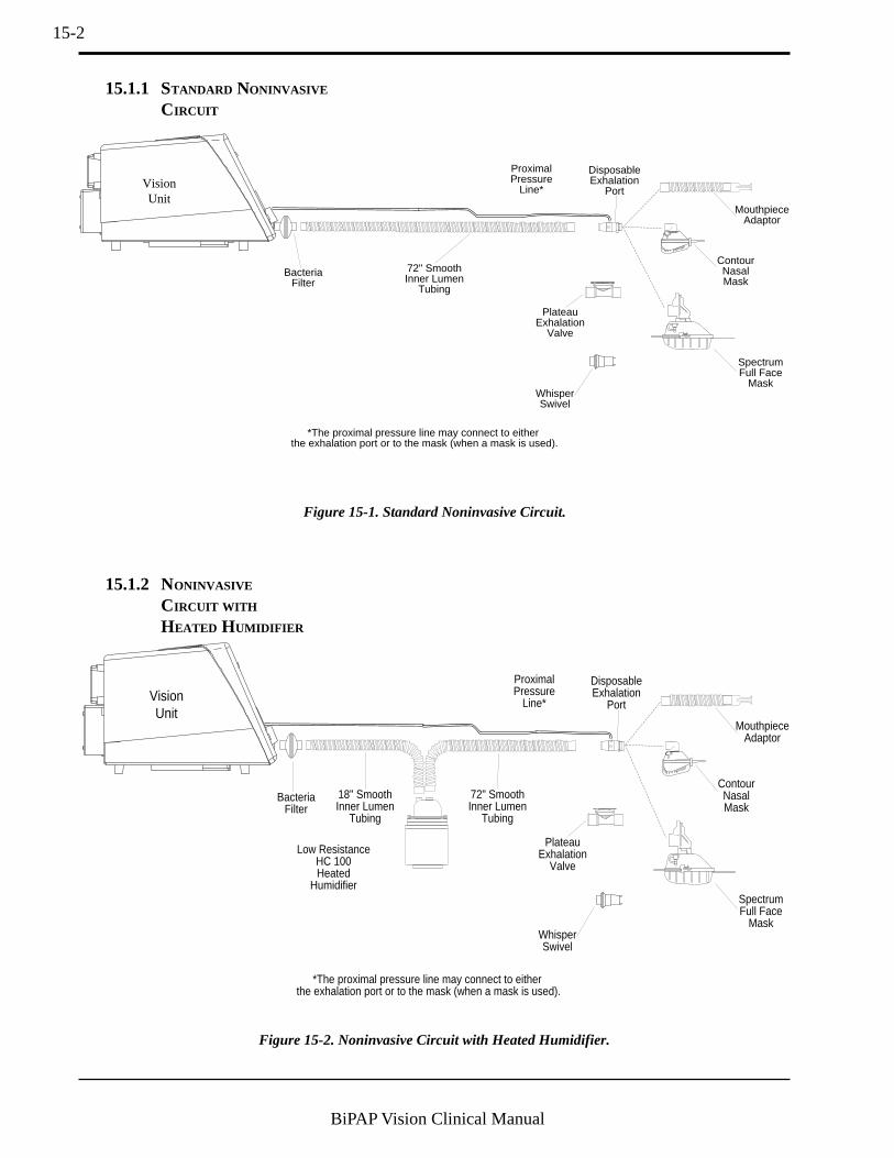
15-2
BiPAP Vision Clinical Manual
ProximalPressure
Line*
DisposableExhalation
Port
PlateauExhalation
Valve
72" SmoothInner Lumen
Tubing
BacteriaFilter
*The proximal pressure line may connect to either the exhalation port or to the mask (when a mask is used).
WhisperSwivel
SpectrumFull Face
Mask
ContourNasalMask
MouthpieceAdaptor
VisionUnit
15.1.1 STANDARD NONINVASIVE
CIRCUIT
Figure 15-1. Standard Noninvasive Circuit.
ProximalPressure
Line*
DisposableExhalation
Port
PlateauExhalation
Valve
72" SmoothInner Lumen
Tubing
18" SmoothInner Lumen
Tubing
BacteriaFilter
Low ResistanceHC 100Heated
Humidifier
*The proximal pressure line may connect to either the exhalation port or to the mask (when a mask is used).
WhisperSwivel
SpectrumFull Face
Mask
ContourNasalMask
MouthpieceAdaptor
VisionUnit
Figure 15-2. Noninvasive Circuit with Heated Humidifier.
15.1.2 NONINVASIVE
CIRCUIT WITH
HEATED HUMIDIFIER

15-3
BiPAP Vision Clinical Manual
InletPort
OutletPort
PressurePort
PatientConnection
BacteriaFilter
SmoothInner Lumen Tubing
Low ResistanceHeated Humidifier
Proximal Pressure
LineHoseClip
HoseClip
DisposableExhalation
PortTube
Hanger
Proximal PressureLine Hydrophobic
Bacteria FilterVisionUnit
SmoothInner Lumen Tubing
SmoothInner Lumen
Tubing
WaterTrap
Right AngleTrachElbow
TemperatureProbe
Adapter
15.1.3 INVASIVE CIRCUIT
Figure 15-3. Recommended Invasive Circuit Configuration.
NOTE: To ensure adequate humidification during invasive applications, the Fisher & Paykel MR 730 RespiratoryHumidifier is recommended.
NOTE: Tubing lengths between circuit components can vary, however, the maximum length of the entire circuit shouldnot exceed 72 inches.

15-4
BiPAP Vision Clinical Manual
The following accessory items may be used with the Vision System:
—Vision Disposable Circuit (noninvasive):Includes 72" tubing, exhalation port, proximal pressure line,hanger, and hose clips.
—Vision Disposable Circuit (invasive):Includes tubing, water trap, exhalation port, temperature
probe, proximal pressure line, hanger, and hose clips.
—Reusable CircuitIncludes 6' reusable circuit.
—Accessories:6" disposable circuit tubing18" disposable circuit tubing36" disposable humidifier tubing72" disposable tubingDisposable proximal pressure lineO2 enrichment attachmentBacteria filterMobile Stand II
—Disposable exhalation port—Whisper Swivel exhalation port—Plateau Exhalation Valve
15.2 Circuits andAccessories
15.3 Exhalation Ports
—Masks:Disposable vinyl nasal masksReusable contour nasal masksSpectrum® full face masksComfort Flap® mask accessoryDisposable mouthpiece adapter
—Accessories:Disposable headgearReusable headgearChin strapSoftcap™
Slip-on spacersQuick ClipSimplestrap™
15.4 Masks andRelated Accessories
15.5 Humidifiers —Fisher & Paykel HC 100 Heated Humidifier(recommended for noninvasive applications only)
—Fisher & Paykel MR 730 Heated Humidifier(recommended for invasive applications)

16-1
BiPAP Vision Clinical Manual
Chapter 16: Specifications
ENVIRONMENTAL
Operating Storage
Temperature
Humidity
Atmospheric Pressure
4.4° C to 40° C0 to 95% Relative
(non-condensing)
83 to 102 kPa
-20° C to 60° C0 to 95% Relative
(non-condensing)
83 to 102 kPa
Dimensions:
Weight:
AC Voltage:
Mains Fusing:
AC Frequency:
AC Current:
Protection against electric shock:
Degree of protection againstelectric shock:
Degree of protection againstharmful ingress of water:
Electromagnetic Compatibility:
Output:
Dynamic Regulation:
StaticRegulation:
At the base: 16" (L) x 14 3/8" (W) x10 5/8" (H)(40.6 cm x 36.5 cm x 27 cm)
34 lbs (15.4 kg)
100/120/230/240 V
100 to 120 V —3.5 A Time Delay, 250 V, 5 x 20 mmRespironics Part Number 582259
220 to 240 V —T1.6 A, 250 V, 5 x 20 mmRespironics Part Number 582099
50/60 Hz
3.0 A maximum
Class I
BF
Ordinary Equipment IPX0
The Vision Ventilatory Support System meets the requirements ofIEC 601-1-2 and thus complies with the EMC Directive 89/336/EEC.
4 to 40 cm H2O
± 2 cm H2O at sinusoidal flow @ ± 100 L/min
± 2 cm H2O from -60 to 120 L/min
PHYSICAL
ELECTRICAL
PRESSURE
CAUTION: Use only Respironics replacement fuses.

16-2
BiPAP Vision Clinical Manual
CONTROL ACCURACY
TimedInspiration:
Rate:
OxygenConcentration:
Pressure:
Volume:
Flow:
SpontaneousTrigger:
SpontaneousCycle:
Pressure Range:
Inlet Fitting:
Alarm Battery:
Data RetentionBattery:
± 0.2 sec of the set point
± 1 BPM of the set point
Within ±10% of setting or ±3% FiO2, whichever is greater, at 500 ml tidalvolume and a respiratory rate of 15 BPM
± 1 cm H2O
± 25 ml, + 10%(tested at tidal volume ≥ 500 ml)
± 10% (during stable conditions)
—Shape Trigger—Volume 6 cc above Vleak
—Spontaneous Expiratory Threshold (SET)—Shape Cycle—IPAP maximum of 3.0 sec—Flow Reversal
50 to 100 psig
DISS male oxygen connector
NiCADSupply: 3.6 Vdc, 110 mAh
Type: Lithium CellSupply: + 2.8 VDC, 49 mAh
DISPLAY ACCURACY
TRIGGER
OXYGEN MODULE INLET
INTERNAL BATTERIES
INLET FILTER
Ultra Fine Disposable—Respironics Reorder# 582101 (pack of 6 filters)
NURSE CALL /REMOTE ALARM CONNECTOR
Voltage: 50 VDC or 25 VAC maximumCurrent: 1 Amp maximum

16-3
BiPAP Vision Clinical Manual
CONTROL RANGES & I NCREMENTS
PARAMETERS
ALARMS
ALARM
High Pressure
Low Pressure
Low Pressure Delay
Apnea
Low MinuteVentilation
High Rate
Low Rate
CONTROLRANGE
5 to 50 cm H2O
0 to 40 cm H2O
0 to 60 sec
Disabled; 20 to 40 sec
0 to 99 L/min
4 to 120 BPM
4 to 120 BPM
CONTROLINCREMENTS
1 cm H2O
1 cm H2O
1 sec
4 set points:Disabled, 20, 30, 40 sec
1 L/min
1 BPM
1 BPM
PARAMETER
IPAP
EPAP
CPAP
Rate
Timed Inspiration
IPAP Rise Time
Oxygen Concentration(%O2)
CONTROLRANGE
4 to 40 cm H2O
4 to 20 cm H2O
4 to 20 cm H2O
4 to 40 BPM
0.5 to 3.0 sec
.05 to .4 sec
21 to 100%
CONTROLINCREMENTS
1 cm H2O
1 cm H2O
1 cm H2O
1 BPM
0.1 sec
4 set points:.05, .1, .2, .4 sec
4% from 21 to 25%5%from 25 to 100%
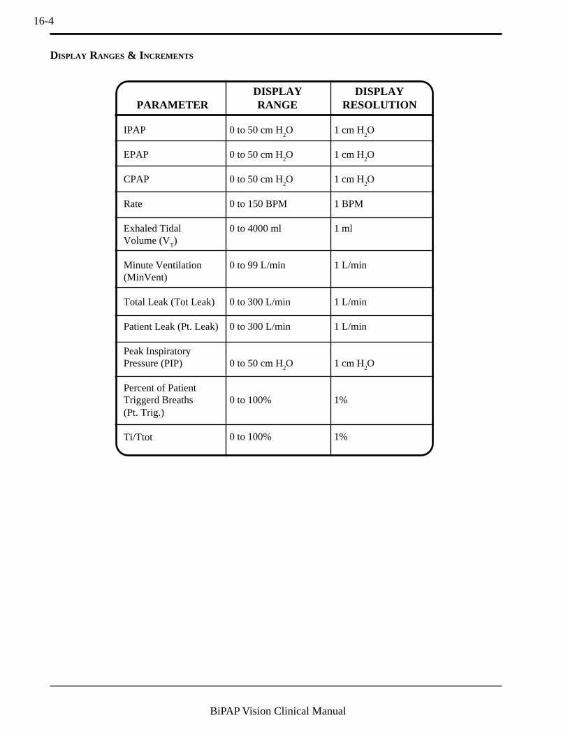
16-4
BiPAP Vision Clinical Manual
DISPLAY RANGES & I NCREMENTS
PARAMETER
IPAP
EPAP
CPAP
Rate
Exhaled TidalVolume (VT)
Minute Ventilation(MinVent)
Total Leak (Tot Leak)
Patient Leak (Pt. Leak)
Peak InspiratoryPressure (PIP)
Percent of PatientTriggerd Breaths(Pt. Trig.)
Ti/Ttot
DISPLAYRANGE
0 to 50 cm H2O
0 to 50 cm H2O
0 to 50 cm H2O
0 to 150 BPM
0 to 4000 ml
0 to 99 L/min
0 to 300 L/min
0 to 300 L/min
0 to 50 cm H2O
0 to 100%
0 to 100%
DISPLAYRESOLUTION
1 cm H2O
1 cm H2O
1 cm H2O
1 BPM
1 ml
1 L/min
1 L/min
1 L/min
1 cm H2O
1%
1%
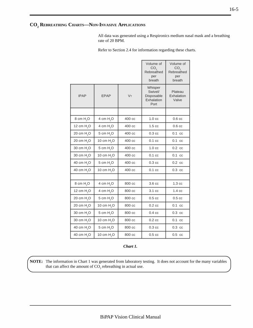
16-5
BiPAP Vision Clinical Manual
CO2 REBREATHING CHARTS—NON-INVASIVE APPLICATIONS
Refer to Section 2.4 for information regarding these charts.
Chart 1.
NOTE: The information in Chart 1 was generated from laboratory testing. It does not account for the many variablesthat can affect the amount of CO2 rebreathing in actual use.
foemuloVOC 2
dehtaerbeRrephtaerb
foemuloVOC 2
dehtaerbeRrephtaerb
PAPI PAPE VT
repsihW/leviwS
elbasopsiDnoitalahxE
troP
uaetalPnoitalahxE
evlaV
Hmc8 2O Hmc4 2O cc004 cc0.1 cc6.0
Hmc21 2O Hmc4 2O cc004 cc5.1 cc6.0
Hmc02 2O Hmc5 2O cc004 cc3.0 cc1.0
Hmc02 2O Hmc01 2O cc004 cc1.0 cc1.0
Hmc03 2O Hmc5 2O cc004 cc0.1 cc2.0
Hmc03 2O Hmc01 2O cc004 cc1.0 cc1.0
Hmc04 2O Hmc5 2O cc004 cc3.0 cc2.0
Hmc04 2O Hmc01 2O cc004 cc1.0 cc3.0
Hmc8 2O Hmc4 2O cc008 cc6.3 cc3.1
Hmc21 2O Hmc4 2O cc008 cc1.3 cc4.1
Hmc02 2O Hmc5 2O cc008 cc5.0 cc5.0
Hmc02 2O Hmc01 2O cc008 cc2.0 cc1.0
Hmc03 2O Hmc5 2O cc008 cc4.0 cc3.0
Hmc03 2O Hmc01 2O cc008 cc2.0 cc1.0
Hmc04 2O Hmc5 2O cc008 cc3.0 cc3.0
Hmc04 2O Hmc01 2O cc008 cc5.0 cc5.0
All data was generated using a Respironics medium nasal mask and a breathingrate of 20 BPM.

16-6
BiPAP Vision Clinical Manual
OCfOloV 2
dehtaerbeRhtaerbrep
OCfOloV 2
dehtaerbeRhtaerbrep
PAPI PAPE VT
%noitaripsnI
emiT
repsihW/leviwSelbasopsiDnoitalahxE
troP
uaetalPnoitalahxE
evlaV
Hmc8 2O Hmc4 2O cc004 32 cc0.1 cc1.0
Hmc8 2O Hmc4 2O cc004 33 cc4.1 cc1.0
Hmc8 2O Hmc4 2O cc004 05 cc6.2 cc4.0
Hmc8 2O Hmc4 2O cc008 32 cc6.3 cc2.0
Hmc8 2O Hmc4 2O cc008 33 cc6.3 cc2.0
Hmc8 2O Hmc4 2O cc008 05 cc6.4 cc0.1
Chart 2.
NOTE: The information in Chart 2 was generated from laboratory testing. It does not account for the many variablesthat can affect the amount of CO
2 rebreathing in actual use.
tneitaPscinoripseR tneitaPscinoripseR tneitaPscinoripseR tneitaPscinoripseR tneitaPscinoripseRecafretnI
ecapsdaeD ecapsdaeD ecapsdaeD ecapsdaeD ecapsdaeDemuloV
ksaMlasaNetiteP cc111
ksaMlasaNllamS cc411
ksaMlasaNllamS-muideM cc941
ksaMlasaNmuideM cc451
ksaMlasaNediW-muideM cc371
ksaMlasaNworraN-egraL cc061
ksaMlasaNegraL cc091
ksaMecaFlluFetiteP cc522
ksaMecaFlluFllamS cc082
ksaMecaFlluFmuideM cc004
ksaMecaFlluFegraL cc235
retpadAeceiphtuoM)ebutnoisnetxesedulcni(
cc35
Chart 3.
The total volume of the Mouthpiece Adapter, including its extension tube, is 53 cc. However, unlike the masks dis-cussed above, none of this volume is reduced in actual use when it is applied to the patient. Therefore, the total volumeof the Mouthpiece Adapter should be considered as deadspace in assessing CO2 rebreathing potential.

16-7
BiPAP Vision Clinical Manual
CO2 REBREATHING CHARTS—I NVASIVE APPLICATIONS
Refer to Section 2.4 for information regarding these charts.
NOTE: The information in Chart 4 was generated from laboratory testing. It does not account for the many variablesthat can affect the amount of CO2 rebreathing in actual use. Pressures higher than those listed produced zero ornegligible CO
2 volume readings. Rebreathed CO
2 volumes are generally lower in invasive applications due to
the elimination of mask deadspace.
All data was generated using approved Respironics invasive circuit at abreathing rate of 20 BPM with I:E = 1:2 (% Inspiration = 50).
OCfOloV 2
dehtaerbeRhtaerbrep
OCfOloV 2
dehtaerbeRhtaerbrep
PAPI PAPE VT
repsihWroleviwSelbasopsiD
tiucriC
uaetalPnoitalahxE
evlaV
Hmc8 2O Hmc4 2O cc004 cc0.1 cc0.1
Hmc21 2O Hmc8 2O cc004 cc0.1 cc5.0
Hmc8 2O Hmc4 2O cc008 cc5.5 cc0
Hmc21 2O Hmc8 2O cc008 cc05.1 cc0
Chart 4.

16-8
BiPAP Vision Clinical Manual

I-1
BiPAP Vision Clinical Manual
Index
A
AC Inlet 4-13Accessories 15-1, 16-1
Exhalation Ports 15-4Standard Noninvasive Circuit 15-2
Adjustable Alarms 12-1Adjusting
% Oxygen 8-3BPM 9-5CPAP Level 8-3CPAP Parameters 8-3EPAP Level 9-4IPAP Level 9-4IPAP Rise Time 9-5S/T Parameters 9-4Timed Inspiration 9-5
Adjustment Knob 4-2Alarm Battery 4-14Alarm Description
Check Ventilator 3-12Exhalation Port Alarm 3-12Ventilator Inoperative 3-12
Alarm Reset Hard Key 4-7Alarm Silence Hard Key 4-7Alarms
Adjustable 12-1and Troubleshooting 12-1CPAP Mode, Adjusting 8-7Description 12-3Hard Keys 4-7Help Key 8-8, 9-11Overview 12-1Principles of Operation 3-12S/T Mode, Adjusting 9-10System 12-1Testing 10-3Visual Indications 12-2
Alarms and Troubleshooting 12-1Alarms Hard Key 4-5Apnea Alarm
CPAP Mode 8-7S/T Mode 9-10
B
Bacteria Filter 6-1
C
Cautions 2-4Patient 2-6
Change Mode Flow Chart 5-2Change Mode Screen
CPAP 8-2S/T 9-3
Changing ModesAdjusting BPM 9-5Adjusting CPAP Parameter 8-3Adjusting EPAP 9-4Adjusting IPAP 9-4Adjusting IPAP Rise Time 9-5Adjusting Timed Inspiration 9-5
CPAP 8-2S/T 9-3Selecting CPAP Parameters 8-3
Check Ventilator Indicator 3-12, 4-8Circuit Configurations 15-1Circuits and Accessories 15-4Cleaning 14-1CO2 Rebreathing 2-5Connectors
Diagnostic 4-14Grounding Stud 4-14Nurse Call/Remote Alarm 4-14
Contraindications 2-6Controls
Alarm Keys 4-7Graph Control Keys 4-6Operational Hard Keys 4-4Rear Panel 4-13Soft Keys 4-3
Controls and Displays 4-1Overview 4-1
CPAP Mode 8-1Changing to 8-2Modifying Alarm Parameters 8-6Modifying Parameters 8-4Overview 8-1
Cycle to EPAP 3-11
D
Data Display Area 4-9Data Values 4-10Descriptors, Soft Key 4-3Design
and Operation 3-2Electronics System 3-2Flow Analysis 3-7Maximum IPAP Time 3-11Oxygen Module 3-4Pneumatic System 3-5Sensitivity 3-9Shape Signal 3-10Spontaneous Expiratory Threshold 3-11Volume Trigger 3-10
Diagnostic Connector 4-14Diagnostic Testing 3-12Discomfort with Mask 12-10Disconnect 3-6Display 3-1Display Values
CPAP 4-10EPAP 4-10Estimated Exhaled Minute Ventilation 4-11Estimated Exhaled Tidal Volume 4-10IPAP 4-10Leak 4-11Monitoring Screen 4-10Parameters Screen 4-11Peak Inspiratory Pressure 4-10, 4-11Rate 4-10

I-2
BiPAP Vision Clinical Manual
E
Electrical Cord 6-2EPAP 4-10Estimated Exhaled Minute Ventilation 4-11Estimated Exhaled Tidal Volume 4-10Exhalation Port Alarm 3-12Exhalation Port Test 3-14, 6-4
Results 6-5Exhalation Ports 15-4Expiratory Flow Rate Adjustment 3-8
F
Flow Analysis 3-7Flow Charts 5-1
Change Mode 5-2Modify Alarms 5-4Modify Parameters 5-3Start-Up 5-1
Flow Reversal 3-11Flow Scale, Modifying 11-3Freeze/Unfreeze Hard Key 4-6Freeze/Unfreeze Key 11-5Front Panel
Hard Keys 4-4Illustrated 4-1Patient Interface Port 4-2Pressure Port 4-2Soft Key Descriptors 4-3
Fuses, Replacing 14-3
G
Graph Control Keys 4-6Graphic Display 4-9
Data Display Area 4-9Data Values 4-10Freezing and Unfreezing 11-5Graphic Display Area 4-9Mode/Message Area 4-9
Graphic Display Area 4-9Modifying 11-1
GraphsScale Ranges and Increments 11-4
Grounding Stud 4-14
H
Hard KeysAlarm Keys 4-7Alarm Reset 4-7Alarm Silence 4-7Alarms Key 4-5Freeze/Unfreeze Key 4-6Graph Control Keys 4-6Mode Key 4-5Monitoring 4-4Operational Group 4-4Parameters Key 4-5Scale Key 4-6
Help KeyCPAP 8-8S/T Mode 9-11
High BPMCPAP Mode 8-8S/T Mode 9-11
High Pressure AlarmCPAP Mode 8-7S/T Mode 9-10
Hours at Pressure 10-5
I
IndicatorsCheck Ventilator 4-8Ventilator Inoperative 4-8Warning 4-8
Inlet FilterSpecification 16-2
Installing the Filter 14-2Intended Use 2-6Invasive Applications 2-7IPAP 4-10
L
LanguageChanging 6-7
LCD 3-1Leak 4-11Leak Compensation 3-8Leak Tolerance 3-8Liquid Crystal Display 3-1Low BPM
CPAP Mode 8-8S/T Mode 9-11
Low Minute VentilationCPAP Mode 8-8S/T Mode 9-11
Low Pressure AlarmCPAP Mode 8-7S/T Mode 9-10
Low Pressure Alarm DelayCPAP Mode 8-7S/T Mode 9-10
M
Maintenance 14-1Replacing the Fuses 14-3
Major Subsystems 3-2Manual Overview 1-2Mask Discomfort 12-10Masks and Related Accessories 15-4Maximum IPAP Time 3-11Mode Key 4-5Mode/Message Area 4-9Modes of Operation
CPAP 8-1S/T 9-1
Modify Alarms Flow Chart 5-4Modify Alarms Screen
CPAP Mode 8-6S/T Mode 9-9
Modify ParametersCPAP Mode 8-4S/T Mode 9-7
Modify Parameters Flow Chart 5-3Modify Parameters Screen
S/T 9-7Modifying
Flow Scale 11-3Graphic Displays 11-1Pressure Scale 11-3Time Base 11-3Volume Scale 11-3
Modifying Alarm ParametersCPAP Mode 8-6S/T Mode 9-9
MonitoringKey 4-4

I-3
BiPAP Vision Clinical Manual
N
Notes 2-4Nurse Call/Remote Alarm Connector 4-14
O
Operating the UnitFlow Charts 5-1
Operational GroupMonitoring 4-4
Options 4-15System Information 4-15
Options Screen 10-1Adjusting the Display 10-5Hours at Pressure 10-5Testing Alarms 10-3
Overview 1-1Controls and Displays 4-1Front Panel 4-1Manual 1-2
Oxygen Concentrations 3-4, 13-3Oxygen Module 6-1
P
Parameter Retention 4-14Parameters Key 4-5
CPAP Mode 8-4S/T Mode 9-7
Parameters Screen 4-11Patient Cautions 2-6Patient Circuit
Assembly 6-1Connections 4-2
Patient Disconnect 3-6Patient Interface Port 4-2Patient Leak 4-11Peak Inspiratory Pressure 4-10, 4-11Performance Verification 7-1Power Entry Module 4-13, 14-3Pressure Air Flow 3-3Pressure Port 4-2Pressure Scale, Modifying 11-3Pressure Valve Assembly 3-3Principles of Operation 3-1
Air Flow Module 3-3Alarms 3-12Auto-Trak Sensitivity 3-8Design and Operation 3-2Display/Control Subsystem 3-3Electronics System 3-2
Air Flow Module 3-3Display/Control Subsystem 3-3Main Controller Subsystem 3-3Power Supply Subsystem 3-3Pressure Air Flow Subsystem 3-3Pressure Regulation Valve 3-3
Flow Analysis 3-7Flow Reversal 3-11Introduction 3-1Leak Tolerance 3-8Main Controller Subsystem 3-3Maximum IPAP Time 3-11Oxygen Module 3-4Pneumatic System 3-5Power Supply Subsystem 3-3Pressure Air Flow Subsystem 3-3Pressure Regulation Valve 3-3Sensitivity 3-9
Shape Signal 3-10Spontaneous Expiratory Threshold 3-11User Interface 3-13Volume Trigger 3-10
Product Support 1-4
R
Rear Panel 4-13Rebreathing 2-5Remote Alarm Connector 4-14Removing the Filter 14-2
S
S/T Mode 9-1Active Controls 8-1, 9-2Changing to 9-3Modifying Alarm Parameters 9-9Modifying Parameters 9-7Overview 9-1
Scale Hard Key 4-6Scale Key 11-2Scales
Modifying 11-2Self-Test 6-3Sensitivity 3-9Set Up Parameters
S/T Mode 9-3Set-Up
Bacteria Filter 6-1Electrical Cord 6-2Oxygen Module 6-1Patient Circuit 6-1Screen 6-3Voltage Selector 6-2
Set-Up ParametersCPAP Mode 8-2
Setting Up and Starting 6-1Shape Signal 3-10Soft Keys 4-3
Descriptors 4-3Operation 4-3
Specifications 16-1Spontaneous Expiratory Threshold 3-11Spontaneous Trigger to IPAP 3-11Standard Noninvasive Circuit 15-2Standby Mode 3-6Start-up Flow Chart 5-1Start/Stop Switch 6-3Starting the Unit 6-3
Exhalation Port Test 6-4Self-Test 6-3Set-Up Screen 6-3Start/Stop Switch 6-3
Subsystems 3-2Oxygen Module 3-4, 13-3
Symbol Key 1-3System Alarms 12-1System Information
Displaying Options 4-15System Set-Up 6-1
T
Testing, Self- 3-12Tidal Volume Adjustment 3-9Time Base, Modifying 11-3Total Leak 4-11Total Operating Time 6-3

I-4
BiPAP Vision Clinical Manual
Triggering 3-8Troubleshooting
Mask Discomfort 12-10
U
User Interface 3-13
V
Ventilator Inoperative Indicator 3-12, 4-8Ventilator Warning Indicators 4-8Voltage Selection 14-3Voltage Selector 6-2Volume Scale, Modifying 11-3Volume Trigger 3-10
W
Warnings 2-1Warnings, Cautions, and Notes 2-1

I-5
BiPAP Vision Clinical Manual
Limited Warranty
Respironics, Inc. warrants that the BiPAP Vision System shall be free from defects of workmanship and materials andwill perform in accordance with the product specifications for a period of one (1) year from the date of sale byRespironics, Inc. to the dealer. If the product fails to perform in accordance with the product specifications, Respironics,Inc. will repair or replace – at its option – the defective material or part. Respironics, Inc. will pay customary freightcharges from Respironics, Inc. to the dealer location only. This warranty does not cover damage caused by accident,misuse, abuse, alteration, and other defects not related to material or workmanship.
Respironics, Inc. disclaims all liability for economic loss, loss of profits, overhead or consequential damages which maybe claimed to arise from any sale or use of this product. Some states do not allow the exclusion or limitation of incidentalor consequential damages, so the above limitation or exclusion may not apply to you.
This warranty is given in lieu of all other express warranties. In addition, any implied warranties—including anywarranty of merchantability or fitness for the particular purpose—are limited to one year. Some states do not allowlimitations on how long an implied warranty lasts, so the above limitation may not apply to you. This warranty gives youspecific legal rights, and you may also have other rights which vary from state to state.
To exercise your rights under this warranty, contact your local authorized Respironics, Inc. dealer or contact Respironics,Inc. at:
1001 Murry Ridge LaneMurrysville, Pennsylvania 15668-8550
1-800-345-6443 (US and Canada only) or 1-724-387-4000

I-6
BiPAP Vision Clinical Manual
1009031JR 12/04/01