Embed Size (px)
Citation preview

BiPAP A30 & BiPAP A40Original and Silver Series
Service & Technical Reference Manual

PAGE I1066229, VER. 05
© 2015 Koninklijke Philips N.V. All rights reserved.

PAGE II 1066229, VER. 05
LIMITED WARRANTYRespironics, Inc. warrants that the BiPAP A30 / BiPAP A40 systems shall be free from defects of workmanshipand materials and will perform in accordance with the product specifications for a period of two (2) years fromthe date of sale by Respironics, Inc. to the dealer. If the product fails to perform in accordance with the productspecifications, Respironics, Inc.will repair or replace – at its option – the defective material or part. Respironics,Inc. will pay customary freight charges from Respironics, Inc. to the dealer location only. This warranty doesnot cover damage caused by accident, misuse, abuse, alteration, and other defects not related to material orworkmanship.
Respironics, Inc. disclaims all liability for economic loss, loss of profits, overhead, or consequential damageswhich may be claimed to arise from any sale or use of this product. Some states do not allow the exclusion orlimitation of incidental or consequential damages, so the above limitation or exclusion may not apply to you.
Accessories, including, but not limited to, circuits, tubing, leak devices, exhaust valves, filters and fuses, arenot covered under this warranty. The warranty for repairs is 90 days for labor and one year on the part(s) thatwas replaced.
This warranty is given in lieu of all other express warranties. In addition, any implied warranties – including anywarranty of merchantability or fitness for the particular purpose – are limited to two years. Some states do notallow limitations on how long an implied warranty lasts, so the above limitation may not apply to you. Thiswarranty gives you specific legal rights, and you may also have other rights which vary from state to state.
To exercise your rights under this warranty, contact your local authorized Respironics, Inc. dealer or contactRespironics, Inc. at:
1001 Murry Ridge LaneMurrysville, Pennsylvania
15668-85501-724-387-4000
DeutschlandGewerbestrasse 17
82211 Herrsching Germany+49 8152 93060
Revision History

PAGE I1066229, VER. 05
Revision History
REVISION RECORD OF REVISION AUTHOR
00 Initial Revision T. Flowers
01 Added BiPAP A40 information B. Martz
03 • Section 7.0 - Added Silver Series non-Heated Tube Humidifier Bottom Housing P/N 1114891
• Section 7.0 - Added Silver Series Heated Tube Humidifier Heater Plate RP P/N 1099585
• Section 7.2.9 - Amended Kit Inclu-sions in table from “Bottom Housing (with Left Side Panel)” to “Bottom Housing” and removed inclusion of #6 X ¼” screw (x4)
• Table Page 6-2 - Blower Box Bottom (includes Blower Box Mount) changed to Blower Box Bottom (includes Blower Box Seal)
• Table Page 6-2 - Added BiPAP A40 Battery Module Cover RP and BiPAP SOH Keypad RP
S. Waugaman
04 • Version 4 not released.
• Content added in version 4 released in version 5.
05 • Added Heated Tube Humidifier Top Housing RP.
• Added Warning Label Dom U.S. to Humidifier RP Kit Table
• Corrected part descriptions for Left/Right Side Panels and Beauty Covers in RP Kit listing.
• Added BiPAP SOH to Checkout Proce-dure.
S. Waugaman

PAGE II 1066229, VER. 05
This page intentionally blank.

1066229, VER. 05
CHAPTER 1: INTRODUCTION1.0 PRODUCT OVERVIEW ..................................................................................................... 1-1
1.1 SERVICE NOTICE............................................................................................................ 1-1
1.2 SERVICE TRAINING......................................................................................................... 1-1
1.3 PRODUCT SUPPORT STATEMENT .................................................................................... 1-1
CHAPTER 2: WARNINGS, CAUTIONS, & NOTES2.0 WARNINGS..................................................................................................................... 2-2
2.1 CAUTIONS...................................................................................................................... 2-3
2.2 NOTES........................................................................................................................... 2-3
CHAPTER 3: SPECIFICATIONS & CLASSIFICATIONS3.0 THERAPY DEVICE SPECIFICATIONS ................................................................................. 3-1
3.1 ELECTROMAGNETIC EMISSIONS ...................................................................................... 3-4
3.2 ELECTROMAGNETIC IMMUNITY ........................................................................................ 3-5
3.3 RECOMMENDED SEPARATION DISTANCES BETWEEN PORTABLE & MOBILE RF COMMUNICA-TIONS AND THIS DEVICE............................................................................................... 3-7
CHAPTER 4: SETUP4.0 SUPPLYING POWER TO THE DEVICE................................................................................ 4-1
4.0.1 Using AC Power .................................................................................................................... 4-1
4.0.2 Using DC Power .................................................................................................................... 4-2
4.1 DEVICE POWER SOURCE INDICATORS............................................................................. 4-3
4.1.1 AC Power Indicators............................................................................................................. 4-3
4.1.2 DC Power Indicators............................................................................................................. 4-3
4.2 STARTING THE DEVICE ................................................................................................... 4-4
4.3 NAVIGATING THE MENU SCREENS .................................................................................. 4-5
4.4 ACCESSING THE SETUP SCREEN .................................................................................... 4-5
4.5 ACCESSING THE MONITOR SCREEN ................................................................................ 4-7
4.6 CHANGING DEVICE SETTINGS AND ALARMS.................................................................... 4-8
4.6.1 BiPAP A30 Device Settings.................................................................................................. 4-8
4.6.2 BiPAP A40 Device Settings................................................................................................4-10
CHAPTER 5: TROUBLESHOOTING AND ERROR CODES

1066229, VER. 05
5.0 INTRODUCTION................................................................................................................5-1
5.1 INSTALLING THE ANIV TOOLBOX SOFTWARE...................................................................5-1
5.1.1 ANIV Toolbox Installation Process ..................................................................................... 5-2
5.2 READING THE DEVICE’S EVENT (ERROR) LOG .................................................................5-5
5.3 BIPAP A40 INITIAL BASE UNIT, BATTERY MODULE, OR DETACHABLE BATTERY DIAGNOSIS .5-9
5.4 DEVICE FIRMWARE ERROR CODES................................................................................5-13
5.5 FSA TEST STATION ERROR CODES ..............................................................................5-38
CHAPTER 6: REPAIR & REPLACEMENT6.1 REPLACEMENT PART (RP) KITS......................................................................................6-1
6.2 BASE UNIT PRELIMINARY CHECKOUT ..............................................................................6-4
6.3 REPLACEMENT INSTRUCTIONS.........................................................................................6-5
6.3.1 Replacing the Accessory Port Cover, A Series ................................................................. 6-5
6.3.2 Replacing the Right Side Cover .......................................................................................... 6-6
6.3.3 Replacing the User Interface Panel..................................................................................... 6-7
6.3.4 Replacing the Top Cover ..................................................................................................... 6-9
6.3.5 Replacing the Keypad ........................................................................................................ 6-11
6.3.6 Replacing the Left Side Panel ........................................................................................... 6-12
6.3.7 Replacing the Main PCA .................................................................................................... 6-14
6.3.8 Replacing the Blower, Blower Box, and/or PCA Supports ............................................. 6-17
6.3.9 Replacing the Valve Assembly.......................................................................................... 6-21
6.3.10 Replacing the Outlet Flow Path....................................................................................... 6-23
6.3.11 Replacing the Flow Manifold ........................................................................................... 6-24
6.3.12 Replacing the Right Panel Assembly ............................................................................. 6-25
6.3.13 Replacing the Base Cable (6 pin) .................................................................................... 6-26
6.3.14 Replacing the Power Cable Assembly and/or Power Connector Bracket................... 6-27
6.3.15 Replacing the Flow Path Cover and/or Air Path Foam.................................................. 6-29
6.3.16 Replacing the Bottom Enclosure .................................................................................... 6-31
CHAPTER 7: HUMIDIFIER REPAIR AND REPLACEMENT7.0 HUMIDIFIER REPLACEMENT PART (RP) KITS ...................................................................7-1
7.1 HUMIDIFIER PRELIMINARY CHECKOUT..............................................................................7-2
7.2 REPLACEMENT INSTRUCTIONS.........................................................................................7-3
7.2.1 Replacing the Water Chamber Assembly........................................................................... 7-3
7.2.2 Replacing the Tank Top Seal............................................................................................... 7-4

1066229, VER. 05
7.2.3 Replacing the Dry Box Seal ................................................................................................. 7-5
7.2.4 Replacing the Dry Box Assembly/Humidifier Inlet Seal .................................................... 7-6
7.2.5 Replacing the Flip Lid Assembly Non-Heated Tube.......................................................... 7-8
7.2.6 Replacing the Flip Lid Assembly Heated Tube .................................................................. 7-9
7.2.7 Replacing the Humidifier Top Housing............................................................................. 7-10
7.2.8 Replacing the Humidifier Outside Cover .......................................................................... 7-11
7.2.9 Replacing the Humidifier Bottom Housing....................................................................... 7-12
7.2.10 Replacing the Heater Plate Assembly............................................................................. 7-14
7.2.11 Replacing the Slider Docking Latch................................................................................7-16
CHAPTER 8: TESTING & CALIBRATION8.0 SECTION OVERVIEW....................................................................................................... 8-1
8.1 PREVENTIVE MAINTENANCE............................................................................................ 8-1
8.2 CLEANING...................................................................................................................... 8-1
8.2.1 Cleaning and Disinfection for Multiple Users .................................................................... 8-1
8.2.2 Cleaning and Replacing the Filters ..................................................................................... 8-2
8.2.3 Cleaning the Reusable Tubing ............................................................................................ 8-2
8.2.4 Cleaning the Humidifier Tank .............................................................................................. 8-3
8.3 SYSTEM CHECKOUT PROCEDURE ................................................................................... 8-4
8.3.1 Clearing Patient Data............................................................................................................ 8-4
8.3.2 Gather Device Information ................................................................................................... 8-5
8.3.3 System Verification Equipment Required .......................................................................... 8-6
8.3.4 Heated Humidifier Performance Confirmation................................................................... 8-6
8.3.5 System Verification Test ...................................................................................................... 8-8
8.4 REQUIRED EQUIPMENT................................................................................................. 8-12
8.5 DOWNLOADING AND INSTALLING THE TEST SOFTWARE ................................................. 8-16
8.5.1 32 Bit vs. 64 Bit OS Verification......................................................................................... 8-16
8.5.2 Downloading the Philips TS Engine and Field Service Application (FSA).................... 8-18
8.5.3 Compatibility Settings for Windows 7 Users ................................................................... 8-19
8.6 HARDWARE SETUP....................................................................................................... 8-20
8.6.1 COM Port Configuration.....................................................................................................8-21
8.7 QUALIFICATION PROCEDURE ........................................................................................ 8-23
8.8 TESTING A DEVICE ....................................................................................................... 8-24
8.9 RUNNING INDIVIDUAL TESTS......................................................................................... 8-26
8.10 USING THE TOOLBOX APPLICATION ............................................................................ 8-28
8.10.1 Read Error Log.................................................................................................................. 8-28

1066229, VER. 05
8.10.2 Read Serial Number and Model Number ........................................................................ 8-28
8.10.3 Calibrate the Real-time Clock .......................................................................................... 8-29
8.10.4 Set Machine Hours ........................................................................................................... 8-30
8.10.5 Set Session ID................................................................................................................... 8-30
CHAPTER 9: DEVICE SOFTWARE UPGRADING9.0 SECTION OVERVIEW........................................................................................................9-1
9.1 REQUIRED EQUIPMENT....................................................................................................9-1
9.2 UPGRADING THE SOFTWARE AND DEVICE BOOT MONITOR...............................................9-3
9.2.1 Upgrading the Device’s Software........................................................................................ 9-3
9.2.2 Upgrading the Device’s Boot Monitor ................................................................................ 9-3
9.2.3 ANIV Boot Monitor Upgrade Installation Process ............................................................. 9-3
CHAPTER 10: SCHEMATICS10.0 PROPRIETARY STATEMENT..........................................................................................10-1

PAGE 1-11066229, VER. 05
CHAPTER 1: INTRODUCTION
1.0 PRODUCT OVERVIEW
The device augments patient breathing by supplying pressurized air through a patient circuit. It senses thepatient’s breathing effort by monitoring airflow in the patient circuit and adjusts its output to assist in inhalationand exhalation. This therapy is known as Bi-level ventilation. Bi-level ventilation provides a higher pressure,known as IPAP (Inspiratory Positive Airway Pressure), when you inhale, and a lower pressure, known as EPAP(Expiratory Positive Airway Pressure), when you exhale. The higher pressure makes it easier for you to inhale,and the lower pressure makes it easier for you to exhale. The device can also provide a single pressure level,known as CPAP (Continuous Positive Airway Pressure).
1.1 SERVICE NOTICE
The device is designed so that qualified Service Personnel can perform repair and testing procedures.
1.2 SERVICE TRAINING
Respironics offers service training for the device. Training includes complete disassembly of the device,troubleshooting sub-assemblies and components, and necessary safety testing. For more information, contactthe Service Marketing department at:
E-mail: [email protected]: (724) 755-8225
Fax: (724) 755-8230Or your Philips Respironics regional service location
1.3 PRODUCT SUPPORT STATEMENT
For product support, please contact Respironics Customer Satisfaction.
CAUTION
U.S. federal law restricts this device to sale by or onthe order of a physician.
U.S.A. and CanadaPhone:1-800-345-6443Fax: 1-800-886-0245
InternationalPhone: 1-724-387-4000
Fax: 1-724-387-5012

PAGE 1-2 1066229, VER. 05
This page intentionally blank.

PAGE 2-11066229, VER. 05
CHAPTER 2: WARNINGS, CAUTIONS, & NOTES
Warnings, cautions, and notes are used throughout this manual to identify possible safety hazards, conditionsthat may result in equipment or property damage, and important information that must be considered whenperforming service and testing procedures on the device. Please read this section carefully before servicingthe device.
WARNING
Warnings indicate the possibility of injury to people.
CAUTION
Cautions indicate the possibility of damage to equipment.
NOTE
Notes are used to emphasize a characteristic orimportant consideration.

PAGE 2-2 1066229, VER. 05
2.0 WARNINGS
WARNINGS
• To avoid electrical shock, disconnect the electrical supply before servicing this device.
• Do not service this device in the presence of flammable mixtures, gases, anesthetics,or liquids.
• Electronic components used in this device are subject to damage from static electricity.Repairs made to this device must be performed only in an anti-static, ElectrostaticDischarge (ESD) protected environment.
• To assure the safety of the service technician and the specified performance of thedevice, Respironics recommends that only technicians having prior training orexperience servicing NIV devices perform any repairs or adjustments to the device.
• Do not immerse this device in water, solvents, or cleaning solutions.
• This device is not intended for life support.
• Do not use extension cords with this device.
• Do not service the device near a source of toxic or harmful vapors.
• Do not service this device if the room temperature is warmer than 35° C (95° F). If thedevice is used at room temperatures warmer than 35° C (95° F), the temperature ofthe airflow may exceed 41° C (106° F). This could cause irritation or injury to thepatient’s airway.
• Repairs and adjustments must be performed by authorized service personnel only.Unauthorized service could cause injury, invalidate the warranty, or result in costlydamage.
• Inspect electrical cords and cables for damage or signs of wear. Replace if damaged.
• Pins of connectors identified with the ESD warning symbol should not be touched.Connections should not be made to these connectors unless ESD precautionaryprocedures are used. Precautionary procedures include methods to prevent build-upof electrostatic discharge (e.g., air conditioning, humidification, conductive floorcoverings, non-synthetic clothing), discharging one’s body to the frame of theequipment or system or to earth or a large metal object, and bonding oneself by meansof a wrist strap to the equipment or system or to earth.

PAGE 2-31066229, VER. 05
2.1 CAUTIONS
2.2 NOTES
CAUTIONS
• Perform the Performance Verification at regular intervals.Refer to the Testing section of this manual for additionalinformation.
• The device may only be operated at temperatures between5° C (41° F) and 35° C (95° F).
• Do not place liquids on or near the device.
• If this device has been exposed to either very hot or very coldtemperatures, allow it to adjust to room temperature beforeusing or servicing it.
• A properly installed, undamaged reusable foam inlet filter isrequired for proper operation.
NOTE
Refer to the device’s User Manual for additionalWarnings, Cautions, Notes, and Operating Instructions.

PAGE 2-4 1066229, VER. 05
This page intentionally blank.

PAGE 3-11066229, VER. 05
CHAPTER 3: SPECIFICATIONS & CLASSIFICATIONS
This chapter includes specifications and EMC compliance for the Philips Respironics BiPAP A30 / BiPAP A40devices.
3.0 THERAPY DEVICE SPECIFICATIONS
Environmental
Operating Temperature: 5° to 35° C (41° to 95° F)
Storage Temperature: -20° to 60° C (-4° F to 140° F)
Relative Humidity (operating & storage): 15 to 95% (non-condensing)
Atmospheric Pressure: 101 to 77 kPa (0 - 2286 m / 0 - 7500 ft)
Physical
Dimensions: 22W x 18L x 11H cm (8.75” x 7.25” x 4.25”)
Weight (Device with power supply): Approximately 2 Kg (4.4 lbs)
Standards Compliance
This device is designed to conform to the following standards:
• IEC 60601-1: Medical electrical equipment - Part 1: General requirements for safety
• IEC 60601-1-2: General requirements for safety - Collateral standard: Electromagnetic compatibil-ity - Requirements and tests
• ISO 10651-6: Lung ventilators for medical use -- Particular requirements for basic safety and essential performance -- Part 6: Home care ventilatory support devices
• ISO 10993-1 Biological evaluation of medical devices - Part 1: Evaluation and testing (Biocompat-ibility)
• RTCA/DO-160F section 21, category M; Emission of Radio Frequency Energy
Electrical
AC Voltage Source: 90-264 VAC, 47-63 Hz, 1.2 A
DC Power Consumption:
• 12 VDC, 5.0 A (External Battery)
• 24 VDC, 4.2 A (Power Supply)
Maximum power consumption of 100 WATT continuous.
Type of Protection Against Electric Shock: Class II/Internally Powered Equipment
Degree of Protection Against Electric Shock: Type BF Applied Part
Degree of Protection against Ingress of Water (Device and AC power supply): Drip Proof, IP22
Mode of Operation: Continuous
SD Card and SD Card Reader
Use only SD cards and SD card readers available from Philips Respironics, including the following:
• SanDisk Card Reader/Writer - SanDisk ImageMate - REF SDDR-99-A15

PAGE 3-2 1066229, VER. 05
Control Accuracy
Displayed Parameter Accuracy
Noise
Minimum alarm sound level: 60 dB(A)
Parameter Range Accuracy
BiPAP SOH IPAP 4.0 to 35.0 cm H2O ± 2.5 cm H2O*
A30 IPAP 4.0 to 30.0 cm H2O ± 2.5 cm H2O*
A40 IPAP 4.0 to 40.0 cm H2O ± 2.5 cm H2O*
EPAP 4.0 to 25.0 cm H2O ± 2.5 cm H2O*
CPAP 4.0 to 20.0 cm H2O ± 2.5 cm H2O*
Breath Rate 0 to 40 BPM Greater of ± 1 BPM or ± 10% of setting
Inspiration Time 0.5 to 3.0 seconds ± (10% of setting + 0.1 second)
Specifications listed are based on using a standard patient circuit (Philips Respironics 15or 22 mm tubing; Whisper Swivel II).
*Pressure measured at the patient connection port with or without the Humidifier (nopatient flow, with Whisper Swivel II)
Parameter Range Resolution Range
Estimated Leak Rate N/A 0.1 LPM 0 to 175 LPM
Exhaled Tidal Volume Greater of ± 20 ml or ± 20% of reading
1 ml 0 to 2000 ml
Respiratory Rate Greater of ±1 BPM or ±10% of reading
1 BPM 0 to 60 BPM
Exhaled Minute Ventilation Calculation based on Exhaled Tidal Volume and Respiratory Rate
0.1 LPM 0 to 25 LPM
Estimated Patient Pressure ± 2.5 cm H2O 0.1 cm H2O 0 to 40 cm H2O
I:E Ratio Calculation based on Inspiratory time and Expiratory time
0.1 9.9:1 to 1:9.9
Notes: -Displayed parameter accuracies are based on ambient bench top conditions at an altitude of nominally 380 meters. All flow based parameters are expressed in volumetric flow.-Pressure measured at the patient connection port with or without the integrated heated humidifier (no patient flow).

PAGE 3-31066229, VER. 05
A30 Spontaneous Breathing During Power Failure Conditions
A40 Spontaneous Breathing During Power Failure Conditions
Disposal
Separate collection for electrical and electronic equipment per EC Directive 2002/96/EC. Dispose of this devicein accordance with local regulations.
Patient Flow (LPM) Expiratory Resistance*(cm H2O)
Inspiratory Resistance*(cm H2O)
30 <2.1 <2.3
60 <5.3 <5.4
* Includes Humidifier
Patient Flow (LPM) Expiratory Resistance*(cm H2O)
Inspiratory Resistance*(cm H2O)
30 <1.5 <1.5
60 <3.7 <4.1
* Includes Humidifier
PAGE 3-4 1066229, VER. 05
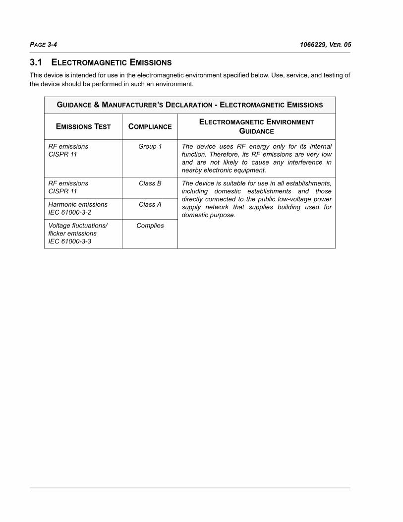
3.1 ELECTROMAGNETIC EMISSIONS
This device is intended for use in the electromagnetic environment specified below. Use, service, and testing ofthe device should be performed in such an environment.
GUIDANCE & MANUFACTURER’S DECLARATION - ELECTROMAGNETIC EMISSIONS
EMISSIONS TEST COMPLIANCEELECTROMAGNETIC ENVIRONMENT
GUIDANCE
RF emissionsCISPR 11
Group 1 The device uses RF energy only for its internalfunction. Therefore, its RF emissions are very lowand are not likely to cause any interference innearby electronic equipment.
RF emissionsCISPR 11
Class B The device is suitable for use in all establishments,including domestic establishments and thosedirectly connected to the public low-voltage powersupply network that supplies building used fordomestic purpose.
Harmonic emissions IEC 61000-3-2
Class A
Voltage fluctuations/flicker emissions IEC 61000-3-3
Complies

PAGE 3-51066229, VER. 05
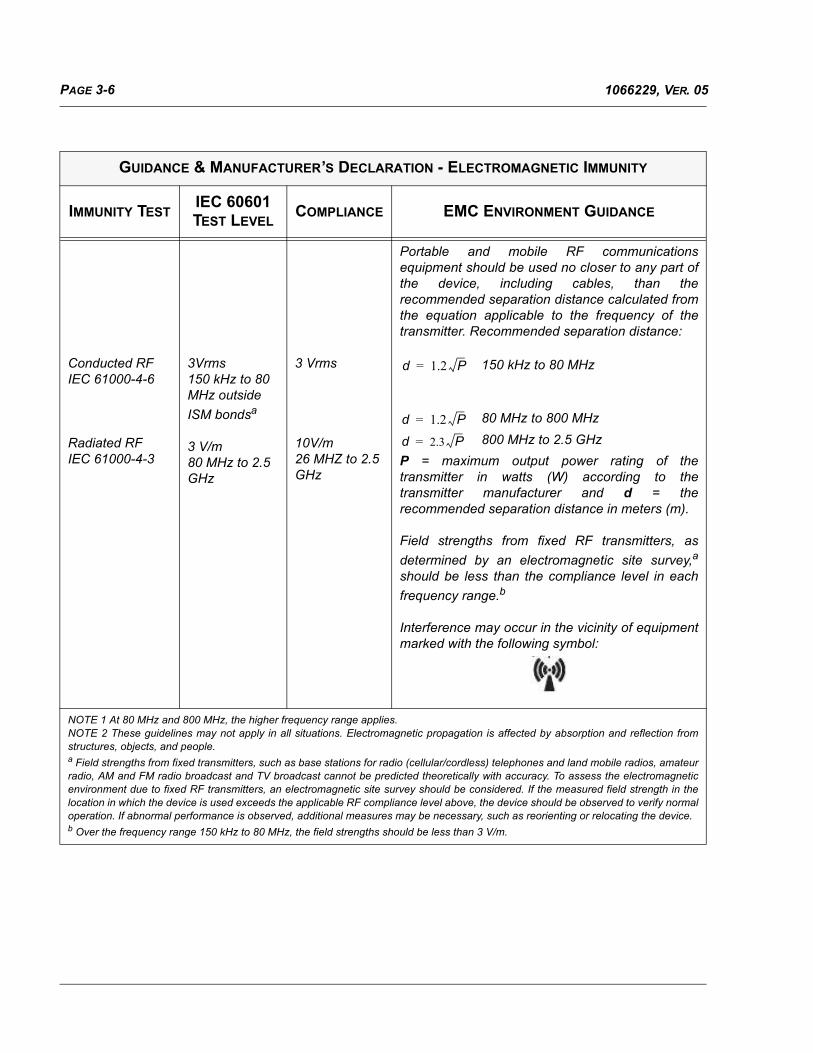
3.2 ELECTROMAGNETIC IMMUNITY
This device is intended for use in the electromagnetic environment specified below. Use, service, and testing ofthe device should be performed in such an environment.
GUIDANCE & MANUFACTURER’S DECLARATION - ELECTROMAGNETIC IMMUNITY
IMMUNITY TESTIEC 60601 TEST
LEVELCOMPLIANCE LEVEL
ELECTROMAGNETIC
ENVIRONMENT- GUIDANCE
ElectrostaticDischarge (ESD)
IEC 61000-4-2
±6 kV contact±8 kV air
±6 kV contact±8 kV air
Floors should be wood,concrete, or ceramic tile. Iffloors are covered withsynthetic material, therelative humidity should beat least 30%.
Electrical fast Transient/burst
IEC 61000-4-4
±2 kV for power supply lines±1 kV for I/O lines
±2 kV for supply mains
±1 kV for I/O lines
Mains power quality should be that of a typical home or hospital environment.
Surge
IEC 61000-4-5
±1 kV Differential Mode±2 kV Common Mode
±1 kV differential mode±2 kV common mode
Mains power quality should be that of a typical home or hospital environment.
Voltage dips, short interruptions, and voltage variations on power supply input lines
IEC 61000-4-11
<5% UT (>95% dip in UT) for 0.5 cycle 40% UT (60% dip in UT) for 5 cycles70% UT (30% dip in UT) for 25 cycles<5% UT (>95% dip in UT) for 5 sec
<5% UT
(>95% dip in UT) for 0.5 cycle 40% UT
(60% dip in UT) for 5 cycles70% UT (30% dip in UT) for 25 cycles<5% UT (>95% dip in UT) for 5 sec
Mains power quality should be that of a typical home or hospital environment. If the user of the device requires continued operation during power mains interruptions, it is recommended that the device be powered from an uninterruptible power supply or a battery.
Power frequency (50/60 Hz) magnetic field IEC 61000-4-8
3 A/m 3 A/m Power frequency magnetic fields should be at levels characteristic of a typical home or hospital environment.
NOTE: UT is the AC mains voltage prior to application of the test level.
PAGE 3-6 1066229, VER. 05
GUIDANCE & MANUFACTURER’S DECLARATION - ELECTROMAGNETIC IMMUNITY
IMMUNITY TESTIEC 60601 TEST LEVEL
COMPLIANCE EMC ENVIRONMENT GUIDANCE
Conducted RF IEC 61000-4-6
Radiated RFIEC 61000-4-3
3Vrms150 kHz to 80 MHz outside
ISM bondsa
3 V/m80 MHz to 2.5 GHz
3 Vrms
10V/m26 MHZ to 2.5 GHz
Portable and mobile RF communicationsequipment should be used no closer to any part ofthe device, including cables, than therecommended separation distance calculated fromthe equation applicable to the frequency of thetransmitter. Recommended separation distance:
P = maximum output power rating of thetransmitter in watts (W) according to thetransmitter manufacturer and d = therecommended separation distance in meters (m).
Field strengths from fixed RF transmitters, as
determined by an electromagnetic site survey,a
should be less than the compliance level in each
frequency range.b
Interference may occur in the vicinity of equipmentmarked with the following symbol:
NOTE 1 At 80 MHz and 800 MHz, the higher frequency range applies. NOTE 2 These guidelines may not apply in all situations. Electromagnetic propagation is affected by absorption and reflection fromstructures, objects, and people.a Field strengths from fixed transmitters, such as base stations for radio (cellular/cordless) telephones and land mobile radios, amateurradio, AM and FM radio broadcast and TV broadcast cannot be predicted theoretically with accuracy. To assess the electromagneticenvironment due to fixed RF transmitters, an electromagnetic site survey should be considered. If the measured field strength in thelocation in which the device is used exceeds the applicable RF compliance level above, the device should be observed to verify normaloperation. If abnormal performance is observed, additional measures may be necessary, such as reorienting or relocating the device.b Over the frequency range 150 kHz to 80 MHz, the field strengths should be less than 3 V/m.
d 1.2 P=
d 1.2 P=
d 2.3 P=
80 MHz to 800 MHz
800 MHz to 2.5 GHz
150 kHz to 80 MHz

PAGE 3-71066229, VER. 05
3.3 RECOMMENDED SEPARATION DISTANCES BETWEEN PORTABLE & MOBILE RF COMMUNICATIONS AND THIS DEVICE
This device is intended for use in an electromagnetic environment in which radiated RF disturbances arecontrolled. Electromagnetic interference may be prevented by maintaining a minimum distance betweenportable and mobile RF communications equipment (transmitters) and this device as recommended in thetable below, according to the maximum output power of the communications equipment.
RATED MAXIMUM POWER
OUTPUT OF TRANSMITTER
(WATTS)
SEPARATION DISTANCE ACCORDING TO FREQUENCY OF TRANSMITTER
(m)
150 kHz to 80 MHz outside ISM Bands
150 kHz to 80 MHz in ISM Bands
80 MHz to 800 MHz 800 MHz to 2.5GHz
0.01 0.12 0.12 0.12 0.23
0.1 0.38 0.38 0.38 0.73
1 1.2 1.2 1.2 2.3
10 3.8 3.8 3.8 7.3
100 12 12 12 23
For transmitters rated at a maximum output power not listed above, the recommended separation distance din meters (m) can be estimated using the equation applicable to the frequency of the transmitter, where P isthe maximum output power of the transmitter manufacturer.Note 1: At 80 MHz and 800 MHz, the higher frequency range applies.Note 2: The ISM (industrial, scientific and medical) bands between 150 kHz and 80 MHz are 6.765 MHz to6.795 MHz; 13.553 MHz to 13.567 MHz; 26.957 MHz to 27.283 MHz; and 40.66 MHz to 40.70 MHz.Note 3: An additional factor of 10/3 is used in calculating the recommended separation distance fortransmitters in the ISM frequency bands between 150 kHz and 80 MHz and in the frequency range of 80MHz and 2.5 GHz to decrease the likelihood that mobile/portable communications equipment could causeinterference if it is inadvertently brought into patient areas.Note 4: These guidelines may not apply in all situations. Electromagnetic propagation is affected byabsorption and reflection from structures, objects and people.
d 1.2 P= d 1.2 P=d 1.2 P= d 2.3 P=

PAGE 3-8 1066229, VER. 05
This page intentionally blank.

PAGE 4-11066229, VER. 05
CHAPTER 4: SETUP
This chapter provides an overview of the system setup including introductory information on the User andProvider modes and menus. Please refer to the device’s User Manual for further information.
4.0 SUPPLYING POWER TO THE DEVICE
The device can operate on either AC or DC power.
4.0.1 USING AC POWER
An AC power cord and power supply is included with the device.
1. Plug the socket end of the power cord into the power supply.
2. Plug the pronged end of the power cord into an electrical outlet that is not controlled by a wall switch.
3. Plug the power supply cord’s connector into the power inlet on the back of the ventilator.
4. Ensure that all connections are secure.
WARNING
• Inspect the power cord often for any signs of damage.Replace a damaged power cord immediately.
• Do not use extension cords with this device.
• Be sure to route the power cord to the outlet in a way thatwill prevent the cord from being tripped over or interferedwith by chairs or other furniture.
• This device is activated when the power cord is connected.
CAUTION
If the device has been exposed to either very hot or very coldtemperatures, allow it to adjust to room temperature(approximately two hours) before beginning setup.
NOTE
• Please refer to the User Manual for additional information.
• If you are servicing the device with a Heated Humidifier, refer to theinstructions included with the humidifier for details on how to supplypower to the device and humidifier.

PAGE 4-2 1066229, VER. 05
5. An accessory clip can be used to secure the power cord to prevent accidental disconnection. Route the cord through the clip and secure the clip to the enclosure of the device using the sup-plied screw, as shown in Figure 4-1.
FIGURE 4-1: CONNECTING THE AC POWER SUPPLY TO THE DEVICE
4.0.2 USING DC POWER
You can operate the ventilator using an external battery or Detachable Battery Pack (BiPAP A40 Only).
EXTERNAL BATTERY
The ventilator can operate from a 12 VDC lead acid battery using the Philips Respironics External BatteryCable. This cable is pre-wired and properly terminated to ensure safe connection of an external battery to theventilator. Battery operating time depends on the characteristics of the battery and usage of the device.
Due to a variety of factors, including battery chemistry, age, and use profile, the capacity of the external batteryas shown on the device display is only an estimate of the actual remaining capacity.
Refer to the instructions supplied with the External Battery Cable for detailed information on how to operate thedevice using an external battery.
DETACHABLE BATTERY (BIPAP A40 ONLY)
Philips Respironics offers a detachable Lithium-Ion battery pack. You can connect the detachable battery to thedevice and recharge the battery using the Philips Respironics Detachable Battery Module. Refer to theinstructions included with your Detachable Battery Pack and Detachable Battery Module for more information.
NOTE
The devices have a locking-type power connector. To avoid damage to theconnector, when disconnecting the power cord, pull the connector at its base,not the cord, to disengage the lock.
NOTE
The detachable battery pack will automatically recharge whenever it isconnected to the therapy device and the device is running on AC Power.

PAGE 4-31066229, VER. 05
4.1 DEVICE POWER SOURCE INDICATORS
There are two power source indicators on the device and the display screen. These indicators are described indetail below.
4.1.1 AC POWER INDICATORS
When AC power is applied to the device and the airflow is off, the green AC LED indicator on the Start/Stopbutton lights. When AC power is applied and the airflow is on, the white AC LED indicator on the Start/Stopbutton lights.
4.1.2 DC POWER INDICATORS
When DC power is applied to the device, battery symbols will appear on-screen to indicate the battery status.The shading in the battery icon indicates the power remaining in the battery. Refer to the Display Symbols tablein Chapter 5 for information on each battery symbol.
BATTERY SYMBOL DEVICE
External Battery A30/A40
Detachable Battery A40

PAGE 4-4 1066229, VER. 05
4.2 STARTING THE DEVICE
FIGURE 4-2: DISPLAY AND CONTROL PANEL
1. After supplying power to the device, press the Start/Stop button. The Startup screen appears momentarily, displaying the device name and software version.
2. The Standby screen then appears, shown in Figure 4-3. It displays the date and time, therapy mode, a patient accessory panel (if a patient accessory is attached), a status panel, and the soft key panel.
FIGURE 4-3: STANDBY SCREEN
3. You can perform the following actions from the Standby screen:
a. If a humidifier is connected, you can activate the humidifier preheat function by pressing the Left (Preheat) key.

PAGE 4-51066229, VER. 05
b. If an accessory module is attached, you can monitor the connection to any attached patient accessory.
c. Access the menu by selecting the Up (Menu) key.
d. Initiate therapy by selecting the Right (Therapy) key. Selecting this key starts the airflow and displays the Monitoring screen.
4.3 NAVIGATING THE MENU SCREENS
When the device is in Limited Menu Access mode, use the following key sequence to enter Full Menu Accessmode:
1. From the Standby or Monitor screen, press the Down button and the Alarm Indicator/Audio Pause button simultaneously for several seconds. This temporarily places the device in Full Menu Access mode.
2. If you perform this key sequence from the Monitor screen, the Main Menu appears. If you perform it from the Standby screen, the Setup screen appears.
3. An audible indicator sounds indicating you are now in Full Menu Access mode.
4. You can access the Options menu and permanently change the Menu Access setting to Full. Oth-erwise, the device will return to Limited mode once you exit the menu screens or if one minute passes without pressing any device buttons.
To navigate through all of the menu screens and settings:
• Use the Up/Down button to scroll through the menu.
• Use the Left and Right buttons to perform the actions specified on the on-screen buttons.
4.4 ACCESSING THE SETUP SCREEN
1. There are two ways to access the Setup screen:
• Select Menu from the Standby screen.
• Perform the Provider Menu Access Key Sequence from the Standby screen.
WARNING
There are two types of Menu Access - Full and Limited. FullMenu Access allows home care providers to alter all availablesettings. Accessing the Full Menu should not be revealed topatients.
PAGE 4-6 1066229, VER. 05
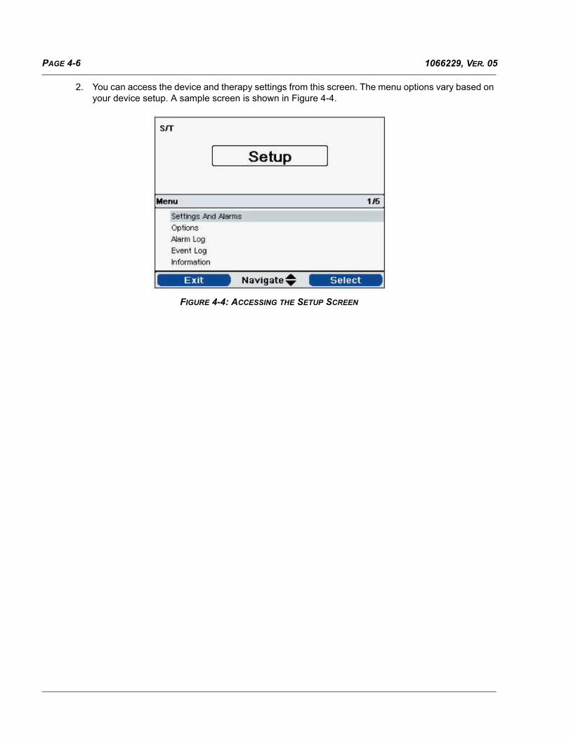
2. You can access the device and therapy settings from this screen. The menu options vary based on your device setup. A sample screen is shown in Figure 4-4.
FIGURE 4-4: ACCESSING THE SETUP SCREEN

PAGE 4-71066229, VER. 05
4.5 ACCESSING THE MONITOR SCREEN
The Monitor screen appears after you press the Therapy key on the Standby screen. There are two versions ofthis screen: Simple View and Detailed View. Samples of both screens are shown in Figure 4-5.
FIGURE 4-5: MONITOR SCREEN
The Monitor screen is divided into several panels, the Monitor panel, Date and Time panel, Patient Accessorypanel (if attached), and the Status panel.
In Simple View, the Monitor screen displays the following:
1. Monitor Panel
a. Therapy mode
b. Flex or AVAPS (if enabled), display next to the therapy mode, along with the value setting

PAGE 4-8 1066229, VER. 05
c. Patient breath indicator displays below the therapy mode
d. Peak pressure symbol appears on the graph according to the maximum Patient Pressure reached during each breath
e. A bar graph displays the current pressure level
f. If enabled, alarm status indicators for Audio Pause, Apnea, and Circuit Disconnect display in the upper right corner
2. The Date/Time panel shows the current date and time.
3. The Patient Accessory panel displays when an accessory is connected to the device. See the Accessories chapter for more information.
4. The Status panel displays certain symbols that indicate features being used, such as Ramp, as well as battery status.
In Detailed View, the same information is shown, except instead of displaying the Date and Time panel, thescreen displays the following measured parameters:
• Patient Pressure
• Exhaled Tidal Volume
• Leak
• Minute Ventilation
• Respiratory Rate
• I:E Ratio
4.6 CHANGING DEVICE SETTINGS AND ALARMS
1. From the Main Menu screen, use the Up/Down key to highlight the Settings and Alarms item.
2. Press the Right key to select Settings and Alarms.
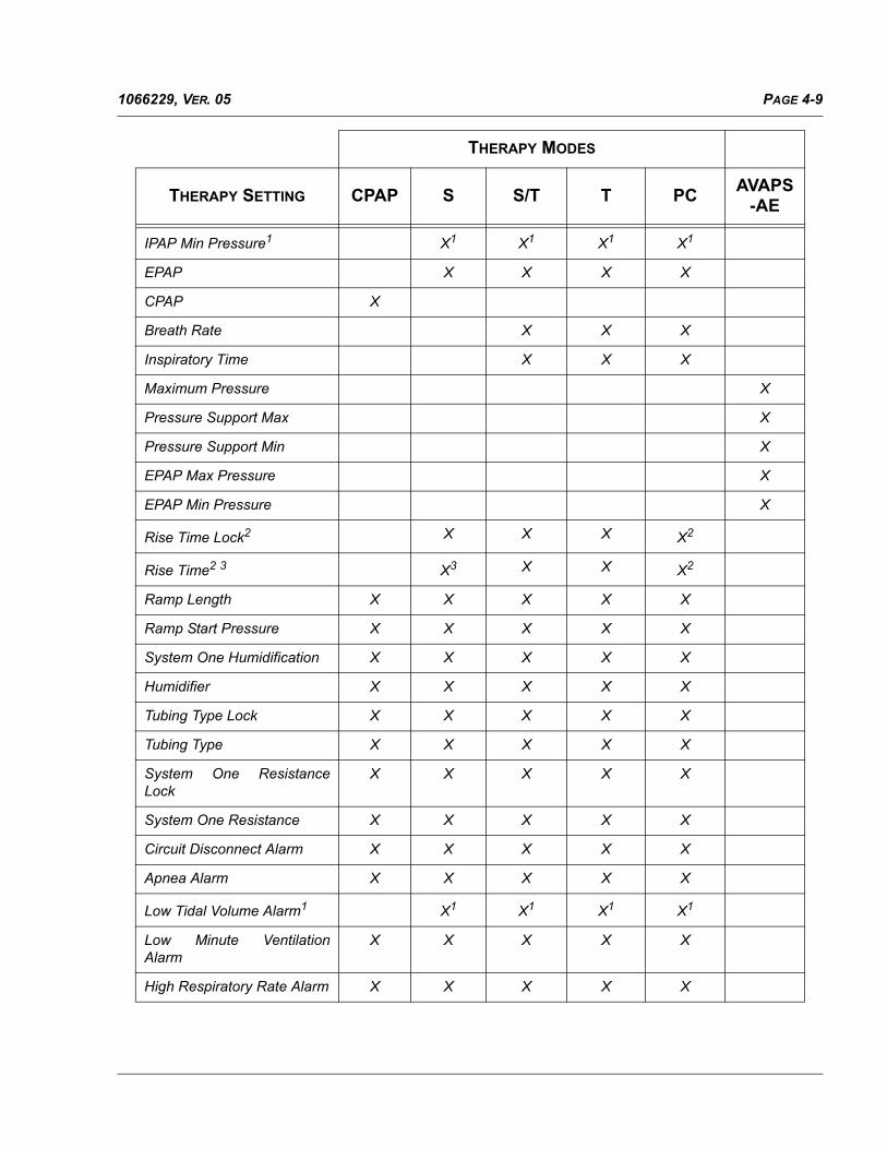
4.6.1 BIPAP A30 DEVICE SETTINGS
The BiPAP A30 device settings are listed below, along with the therapy modes in which they are available.
THERAPY MODES
THERAPY SETTING CPAP S S/T T PCAVAPS
-AE
Mode X X X X X
AVAPS3 X3 X X X
AVAPS Rate1 X1 X1 X1 X1
Flex Lock4 X4
Flex4 X4
Tidal Volume1 X1 X1 X1 X1
IPAP X X X X
IPAP Max Pressure1 X1 X1 X1 X1
PAGE 4-91066229, VER. 05
IPAP Min Pressure1 X1 X1 X1 X1
EPAP X X X X
CPAP X
Breath Rate X X X
Inspiratory Time X X X
Maximum Pressure X
Pressure Support Max X
Pressure Support Min X
EPAP Max Pressure X
EPAP Min Pressure X
Rise Time Lock2 X X X X2
Rise Time2 3 X3 X X X2
Ramp Length X X X X X
Ramp Start Pressure X X X X X
System One Humidification X X X X X
Humidifier X X X X X
Tubing Type Lock X X X X X
Tubing Type X X X X X
System One ResistanceLock
X X X X X
System One Resistance X X X X X
Circuit Disconnect Alarm X X X X X
Apnea Alarm X X X X X
Low Tidal Volume Alarm1 X1 X1 X1 X1
Low Minute VentilationAlarm
X X X X X
High Respiratory Rate Alarm X X X X X
THERAPY MODES
THERAPY SETTING CPAP S S/T T PCAVAPS
-AE

PAGE 4-10 1066229, VER. 05
4.6.2 BIPAP A40 DEVICE SETTINGS
1. Only available when AVAPS is enabled.
2. Not available when AVAPS is enabled.
3. Not available when Flex is enabled.
4. Flex is not available when AVAPS is enabled.
NOTE
For additional information about the device’s alarms, refer to the device’s User Manual.
THERAPY MODES
THERAPY SETTING CPAP S S/T T PC AVAPS-AE
Trigger Type X X X X X
Auto-Trak X X X X X
Auto-Trak (Sensitive) X X X X X
Flow Trigger X X X X X
Flow Trigger Sensitivity X X X X X
Flow Cycle Sensitivity X X X X
CPAP X
Flex Lock X3
Flex X3
AVAPS X2 X X X
AVAPS Rate X1 X1 X1 X1 X
Tidal Volume X1 X1 X1 X1 X
IPAP Max Pressure X1 X1 X1 X1
IPAP Min Pressure X1 X1 X1 X1
IPAP X X X X
THERAPY MODES
THERAPY SETTING CPAP S S/T T PCAVAPS
-AE

PAGE 4-111066229, VER. 05
EPAP X X X X
Breath Rate X X X X
Inspiratory Time X X X X4
Maximum Pressure X
Pressure Support Max X
Pressure Support Min X
EPAP Max Pressure X
EPAP Min Pressure X
Rise Time Lock X X X X X
Rise Time X2 X X X X
Ramp Start Pressure X X X X X
Low Tidal Volume X1 X1 X1 X1 X
1. Only available when AVAPS is enabled.
2. AVAPS and Rise Time are not available when FLEX is enabled.
3. Flex is not available when AVAPS is enabled.
4. Inspiratory time is only available in AVAPS-AE when the breath rate is set between 1 and 40 BPM.
NOTE
For additional information about the device’s alarms, refer to the device’s User Manual.
THERAPY MODES
THERAPY SETTING CPAP S S/T T PC AVAPS-AE

PAGE 4-12 1066229, VER. 05
This page intentionally blank.

PAGE 5-11066229, VER. 05
CHAPTER 5: TROUBLESHOOTING AND ERROR CODES
5.0 INTRODUCTION
This section provides instructions for viewing the devices’ error log as well as a description of the error codes.
Install the ANIV Toolbox first to the default location. If you choose not to install to the default location, recordthe location of the installation directory. You will need the installation directory in the second part of ANIVToolbox installation (LogDogg installation).
5.1 INSTALLING THE ANIV TOOLBOX SOFTWARE
The ANIV Toolbox will provide you with the necessary tools to view the device’s error/event log. To downloadthe software you must log onto my.respironics.com
FIGURE 5-1: MY.RESPIRONICS.COM
Once you have opened the Service and Software Documentation page, click on the BiPAP A30/A40 OriginalSeries or BiPAP A30/A40 Silver Series (depending on the device) link on the left side of the page. Click on theDownload button adjacent to the software you wish to install and follow the on-screen prompts to install thesoftware.
Login Here
http://my.respironics.com
Service Software and Documentation Link

PAGE 5-2 1066229, VER. 05
FIGURE 5-2: BIPAP A30/A40 SERVICE SOFTWARE LINK
5.1.1 ANIV TOOLBOX INSTALLATION PROCESS
1. Click on the Download button adjacent to the ANIV Toolbox.
2. Save the ANIV Toolbox Installer to your PC (default directory is recommended).
FIGURE 5-3: INSTALLATION LOCATION
FIGURE 5-4: LICENSE AGREEMENT (TWO LICENSE AGREEMENT WINDOWS WILL APPEAR)

PAGE 5-31066229, VER. 05
FIGURE 5-5: START INSTALLATION
FIGURE 5-6: INSTALLATION COMPLETE

PAGE 5-4 1066229, VER. 05
3. After you have installed the ANIV Toolbox, the LogDogg installer will begin automatically. Select the same directory that you installed the ANIV Toolbox when the following appears:
FIGURE 5-7: LOGDOGG INSTALL
If you selected the default location during ANIV Toolbox software installation, the LogDogg installation locationshould be as follows:
• For 32 Bit OS - C:\Program Files\ANIV Toolbox
• For 64 Bit OS - C:\Program Files (x86)\ANIV Toolbox
Once you have installed the ANIV Toolbox, you will be prompted to restart the PC. Restart the PC prior to usingthe ANIV Toolbox.
NOTE
To determine whether you have a 32 bit or 64 bitsystem, refer to section 32 Bit vs. 64 Bit OSVerification
NOTE
If installed on a Windows 7 OS, go to section Section8.5.3 prior to using the ANIV Toolbox. If theapplication is not installed on a PC using Windows 7OS, disregard this note.

PAGE 5-51066229, VER. 05
5.2 READING THE DEVICE’S EVENT (ERROR) LOG
1. Install a blank SD Card in the device.
2. Press the Start/Stop button once.
FIGURE 5-8: CONTROL PANEL
3. Simultaneously press and hold the Down, Right, and Alarm Indicator/Audio Pause buttons to access all settings.
4. Use the Down button to scroll to Write Event Log to SD Card.
5. Click on the Right User Button below Select on the LCD.
6. Wait for the Writing Successful message on the LCD.
7. Click on the User button below “OK”.
8. Scroll to the “Safely Remove SD Card” option then select “OK”.
9. Remove the SD card from the device and insert it into the PC.

PAGE 5-6 1066229, VER. 05
10. Select Read Event Log from the ANIV Toolbox Software.
FIGURE 5-9: ANIV TOOLBOX
11. When the following screen appears, click on the Browse button.
FIGURE 5-10: READ EVENT LOG
Tool Box Icon on the PC Desktop

PAGE 5-71066229, VER. 05
12. Navigate to the SD Card drive and select the BiPAP-A folder.
FIGURE 5-11: READ EVENT LOG
13. Select the folder that corresponds with the serial number of the device. Only the first eight (8) numbers that follow the letter prefix will be present.
14. Select the .N17 file.
15. Click on the log file as shown in the following illustration, then click on the “OK” button.
FIGURE 5-12: READ EVENT LOG
NOTE
If more than one.N17 file is present, you did not insert a blank SDcard in step 1 of this procedure. Insert a blank SD card into thedevice and repeat steps 2 through 12.

PAGE 5-8 1066229, VER. 05
16. The Event Log will be displayed as follows:
FIGURE 5-13: EVENT LOG
17. Analyze the extracted error log file for events that caused device issues.

PAGE 5-91066229, VER. 05
5.3 BIPAP A40 INITIAL BASE UNIT, BATTERY MODULE, OR DETACHABLE BAT-TERY DIAGNOSIS
This section describes the steps to take to determine if a suspected fault resides within the Base Unit, BatteryModule, or Detachable Battery.
DEVICE ACTION POSSIBLE CAUSE CORRECTIVE ACTION
No Display Audible Alarm Sounding
1. Did battery deplete? Were there any low battery alarms before the device stopped working ?
2. Was battery removed from the battery module?
3. Was battery module disconnected from the ven-tilator?
4. It’s possible that the battery stopped discharging due to battery overheating.1.Connect AC and if “Batt Discharge Stopped – Temp” info alarm is displayed, then allow battery to cool before using it.
5. It’s possible that the battery failed.
6. Connect AC. If battery icon is displayed, and unit does not operate on battery when AC is dis-connected and there are no messages dis-played, then replace battery. If battery was replaced, and unit still does not operate on bat-tery, then replace battery module. If battery and battery module was replaced, and unit still does not operate on battery, then replace unit.
7. Connect AC. If no battery icon is displayed, then proceed to next device action.
1. Connect AC and recharge battery
2. Reconnect Battery.
3. Reconnect Battery Module.
4. Connect AC and if “Batt Discharge Stopped – Temp” info alarm is dis-played, then allow bat-tery to cool before using it.
5. Connect AC and if “Replace Detachable Battery” medium prior-ity (yellow) alarm is dis-played, then replace battery.
6. Device requires service.
7. Proceed to next device action row.
Device running on AC Power and no Battery
Icon on the display
1. Is “Det Batt is connected” information message displayed?
2. Is battery module connected and battery installed in battery module?
1. Reconnect battery mod-ule and/or reconnect bat-tery
2. a) No - connect battery module and install bat-tery. b) Yes - Replace battery. If battery icon still not displayed, then replace battery module. If battery icon still not displayed, then replace unit. c) If no messages, then replace battery. If bat-tery icon still not dis-played, then replace battery module. If battery icon still not displayed, then replace unit.

PAGE 5-10 1066229, VER. 05
Device running on AC Power and the
Detachable battery icon is red empty
1. Is charge icon displayed 1. a) Yes - normal opera-tion so allow battery to charge b) No - if “Replace Detachable Battery” medium priority (yellow) alarm displayed, then replace Detachable bat-tery. If “Replace Detach-able Battery” is still displayed, then replace battery module. If “Replace Detachable Battery” is still displayed, then replace unit.
DEVICE ACTION POSSIBLE CAUSE CORRECTIVE ACTION

PAGE 5-111066229, VER. 05
Battery icon does not have 5 green bars
and there is no charging icon
1. Is AC Connected?
2. Is the “Battery Not Charging - Temp” message displayed?
3. Is the “Detach Battery Not Charging” message displayed?
1. No - connect AC.
2. a) The battery won’t charge because it is too hot, so allow the battery to cool. b) If battery is cool and still not charging then replace the battery. If battery is still not charging, then replace the battery module. If the battery is still not charging, then return device for service.
3. a) If the humidifier is connected, then it’s pos-sible that the humidifier is hearing up and not allowing the battery to charge. After the humid-ifier has reached operat-ing temperature, then the battery should start charging. If the battery is still not charging, then disconnect the humidi-fier and check if the bat-tery is charging. If the battery is still not charging then replace the battery. If battery is still not charging, then replace the battery mod-ule. If the battery is still not charging, then return the device for ser-vice. b) Disconnect and reconnect the bat-tery and battery mod-ule. If the battery is still not charging then replace the battery. If the battery is still not charging, then replace the battery module. If the battery is still not charging, then return the device for service.
DEVICE ACTION POSSIBLE CAUSE CORRECTIVE ACTION

PAGE 5-12 1066229, VER. 05
“Replace Detachable Battery” information
on the screen
1. Is the battery a Philips/Respironics Battery?
2. It’s possible that the battery is past its life cycle. Check the last line of the information menu. Is the “Detach Battery Cycles” is greater than or qual to 500?
3. It’s possible that the battery is past its useful life or there is a problem with the battery, battery module, or unit.
1. No - Replace the bat-tery.
2. Yes - Replace the bat-tery.
3. Replace the battery and if “Replace Detachable Battery” is still displayed then replace the battery module. If ‘Replace Detachable Battery” is still displayed then return the device for service.
Battery Icon has had the lightning bolt for a long time but the
number of green bars is not increasing
No messages are displayed. Replace the Battery
Low Battery alarm sounds quicker than
expected
Operating time can decrease as the battery ages. Replace the Battery
Depleted Battery Alarm sounds quicker than
expected
Operating time can decrease as the battery ages. Replace the Battery
Device shuts down while running on
battery a lot quicker than expected
Operating time can decrease as the battery ages. Replace the Battery
DEVICE ACTION POSSIBLE CAUSE CORRECTIVE ACTION

PAGE 5-131066229, VER. 05
5.4 DEVICE FIRMWARE ERROR CODES
The following table lists the error codes for the Philips Respironics A Series devices.
NOTE
With the exception of error code #65535, error codes greater than 10,000 areparameter change event codes and are for informational purposes only. These codesare not included in the error code table below.Unless noted in the CODE column, all error codes are universal between A30/A40Original Series and Silver Series.
CODE PROBABLE CAUSEVISUAL
INDICATIONACTION
E-0 Program execution error None (Log Only) N/A
E-1 Program execution error System Reboots N/A
E-2 Corrupt software in flash System Reboots • Reinstall software
• Replace PCA
E-3 Defective RAM chip System Reboots Replace PCA
E-4 Defective internal CPU SRAM System Reboots Replace PCA
E-5 Program Execution Error System Reboots N/A
E-6 IRQ stack is 75% filled None (Log Only) N/A
E-7 Program Execution Error System Reboots N/A
E-8 Thread stack is 75% filled None (Log Only) N/A
E-9 Program Execution Error System Reboots • Reinstall software
• Replace PCA
E-10 Program Execution Error System Reboots • Reinstall software
• Replace PCA
E-11 Program Execution Error System Reboots • Reinstall software
• Replace PCA
E-12 Program Execution Error System Reboots • Reinstall software
• Replace PCA
E-13 Program Execution Error System Reboots • Reinstall software
• Replace PCA
E-14 Program Execution Error System Reboots • Reinstall software
• Replace PCA

PAGE 5-14 1066229, VER. 05
E-15 • Parameter Settings corrupted
• EEPROM Memory on PCA was just replaced
VentilatorInoperative
Replace PCA
E-16 SD Card was inserted into the unit. None (Log Only) None – recorded for informational purposes to indicate that the SD card was placed into unit.
E-17 • Parameter Settings corrupted.
• EEPROM on PCA was just replaced.
VentilatorInoperative
Replace PCA
E-18 SD Card was removed from the unit. None (Log Only) None – recorded for informational purposes to indicate that the SD card was removed from the unit.
E-19 Program Execution Error System Reboots N/A
E-20(OriginalSeries)
Defective EEPROM.
(For released software 2.3 and below)
VentilatorInoperative
Replace PCA
E-20(OriginalSeries)
Defective EEPROM.
(For released software 2.6 and Above)
None (Log Only) Replace PCA
E-20(SilverSeries)
Defective EEPROM. VentilatorInoperative
Replace PCA
E-21 • Defective EEPROM.
• Program Execution Error.
VentilatorInoperative
Replace PCA
E-22 Unable to read a valid time from the RTCchip
None (Log Only) Replace PCA
E-23 The time read from the RTC does not matchtime on Host CPU
None (Log Only) Replace PCA
E-24 Faulty SD card “Card Error” Informational Alarm
Use a different SD Card
E-25 Program Execution Error – BIST threadtaking too long to execute
System Reboots N/A
CODE PROBABLE CAUSEVISUAL
INDICATIONACTION

PAGE 5-151066229, VER. 05
E-26 • Foreign object inserted in card slot
• Unformatted card
• Card prematurely removed
“Card Error” Informational Alarm
• Use correct MMC/SD card
• Reformat MMC/SD card
• Re-insert card
• Replace PCA
E-27 • Foreign object inserted in card slot
• Unformatted card
• Card prematurely removed
“Card Error” Informational Alarm
• Use correct MMC/SD card
• Reformat MMC/SD card
• Re-insert card
• Replace PCA
E-28 • Foreign object inserted in card slot
• Unformatted card
• Card prematurely removed
“Card Error” Informational Alarm
• Use correct MMC/SD card
• Reformat MMC/SD card
• Re-insert card
• Replace PCA
E-29 • Foreign object inserted in card slot
• Unformatted card
• Card prematurely removed
“Card Error” Informational Alarm
• Use correct MMC/SD card
• Reformat MMC/SD card
• Re-insert card
• Replace PCA
E-30 • Foreign object inserted in card slot
• Unformatted card
• Card prematurely removed
“Card Error” Informational Alarm
• Use correct MMC/SD card
• Reformat MMC/SD card
• Re-insert card
• Replace PCA
E-31 • Foreign object inserted in card slot
• Unformatted card
• Card prematurely removed
“Card Error” Informational Alarm
• Use correct MMC/SD card
• Reformat MMC/SD card
• Re-insert card
• Replace PCA
E-32 Queue for Debug Log is full System Reboots N/A
CODE PROBABLE CAUSEVISUAL
INDICATIONACTION

PAGE 5-16 1066229, VER. 05
E-33 Key is providing reading that it has beenheld down for 2 minutes
“Keypad Stuck” LowPriority Alarm
• Check the keypad for stuck keys
• Replace PCA
E-34 Write failure for the Debug Log None (Log Only) Replace PCA
E-35 Program Execution Error None (Log Only) • Reinstall software
• Replace PCA
E-36 Watchdog test failed to reset the board. VentilatorInoperative
Replace PCA
E-37 • Unit is not reaching the requestedpressure setting; The Patient Pressuredelivered is less than the targetpressure – 5cm.
• Low pressure sensor reading
• Large amount of drift
• Pinched/blocked tubing
“Pressure Regulation” High
Priority Alarm
• Check Device and Circuit setup if patient circuit is available.
• Check the tubing (inside and outside the device) for leaks, kinks, or blockages.
• Replace the PCA and recalibrate.
E-38 • The measured Breath Rate is greaterthan or equal to the alarm setting.
• False triggering
• Alarm/setting mismatch
• Spontaneous breathing above the alarm
“High Respiratory Rate” High Priority
Alarm
• Check Device and Circuit setup.
• Check the circuit tubing for pinched or blocked tubes if patient circuit available.
• Check the circuit for leaks if patient circuit is available.
• Check the alarm settings against the therapy settings.
• Check the tubing (inside and outside the device) for leaks, kinks, or blockages.
• Replace the PCA and recalibrate.
CODE PROBABLE CAUSEVISUAL
INDICATIONACTION

PAGE 5-171066229, VER. 05
E-39 • The measured Minute Ventilation is lessthan or equal to the alarm setting.
• Alarm/setting mismatch
• High leak
• High breath rate
• Low exhaled tidal volume (flow sensorproblem)
“Low Minute Ventilation” High
Priority Alarm
• Check the tubing (inside and outside the device) for leaks, kinks, or blockages.
• Replace the PCA and recalibrate.
E-40 A recoverable MMC/SD card error. None (Log Only) None – recorded for informational purposes that a recoverable card error occurred.
E-41 • The leak in the system is too small.
• Wrong circuit
• Blocked tubes
• Sensor problems
“Low Circuit Leak” High Priority Alarm
• Check the circuit tubing for pinched or blocked tubes if patient circuit available.
• Check the tubing (inside and outside the device) for leaks, kinks, or blockages.
• Replace the PCA and recalibrate.
E-42 • Spontaneous breathing has not beendetected within the alarm time.
• High leak
“Apnea” High PriorityAlarm
• Check the circuit tubing for pinched or blocked tubes if patient circuit available.
• Check the circuit for leaks if patient circuit is available.
• Check the tubing (inside and outside the device) for leaks, kinks, or blockages.
• Replace the PCA and recalibrate.
CODE PROBABLE CAUSEVISUAL
INDICATIONACTION

PAGE 5-18 1066229, VER. 05
E-43 • High flow condition has been detected.
• High leak
• Flow sensor problem
“Circuit Disconnect” High Priority Alarm
• Check the circuit tubing for pinched or blocked tubes if patient circuit available.
• Check the circuit for leaks if patient circuit is available.
• Check the tubing (inside and outside the device) for leaks, kinks, or blockages.
• Replace the PCA and recalibrate.
E-44 SW rebooted since it was initiated by theuser
System Reboots None – recorded for informational purposes to indicate that a reboot occurred.
E-45 3 reboots occurred within 24 hours. VentilatorInoperative
• Short term - press the Start/Stop key followed by the Right key to reset the machine.
• Examine error log for reasons for reboots. Proceed accordingly
E-46 CPU cannot communicate with the flowsensor using I2C bus.
VentilatorInoperative
Replace PCA
E-47 CPU cannot communicate with the pressuresensor using SPI bus.
VentilatorInoperative
Replace PCA
E-48 CPU cannot communicate with the barometric pressure sensor using I2C bus
None (Log Only) Replace PCA
E-49 CPU cannot communicate with the humidityand temperature sensor using I2C bus
None (Log Only) Replace PCA
CODE PROBABLE CAUSEVISUAL
INDICATIONACTION
PAGE 5-191066229, VER. 05
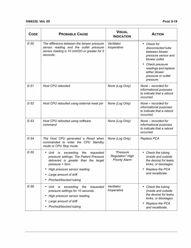
E-50 The difference between the blower pressuresensor reading and the outlet pressuresensor reading is 10 cmH2O or greater for 5seconds.
VentilatorInoperative
• Check for disconnected tube between blower pressure sensor and blower outlet.
• Check pressure readings and replace either blower pressure or outlet pressure
E-51 Host CPU rebooted None (Log Only) None – recorded for informational purposes to indicate that a reboot occurred.
E-52 Host CPU rebooted using external reset pin None (Log Only) None – recorded for informational purposes to indicate that a reboot occurred.
E-53 Host CPU rebooted using software command
None (Log Only) None – recorded for informational purposes to indicate that a reboot occurred.
E-54 The Host CPU generated a Reset whencommanded to enter the CPU Standbymode or CPU Stop mode.
None (Log Only) Replace PCA
E-55 • Unit is exceeding the requestedpressure settings; The Patient Pressuredelivered is greater than the targetpressure + 5cm.
• High pressure sensor reading
• Large amount of drift
• Pinched/blocked tubing
“Pressure Regulation” High
Priority Alarm
• Check the tubing (inside and outside the device) for leaks, kinks, or blockages.
• Replace the PCA and recalibrate.
E-56 • Unit is exceeding the requestedpressure settings for 10 seconds.
• High pressure sensor reading
• Large amount of drift
• Pinched/blocked tubing
VentilatorInoperative
• Check the tubing (inside and outside the device) for leaks, kinks, or blockages.
• Replace the PCA and recalibrate.
CODE PROBABLE CAUSEVISUAL
INDICATIONACTION

PAGE 5-20 1066229, VER. 05
E-57 • AC was disconnected,
• PCA fault,
• Faulty AC-DC input connector,
• AC Power Supply fault,
• Power Cord fault,
• A/D channel fault
“AC Power Disconnected” Medium Priority
Alarm
• Verify AC connected
• Replace AC power Supply
• Replace PCA
E-58 • Lead Acid was disconnected,
• DC Power Cable fault,
• Faulty DC input connector,
• DC Power Cable fuse is open,
• PCA fault,
• A/D channel fault
External Batt Disconnected”
Informational Alarm
• Connect Lead Acid Battery
• Verify DC Power Cable
• Replace DC Power Cable fuse
• Replace PCA
E-59 Low battery - Lead Acid has <= 20 Minutesrun time remaining and it is last availablepower source.
“Low External Battery” Medium
Priority Alarm
• Charge Lead Acid Battery
• Replace Lead Acid Battery
E-60 Depleted battery - Lead Acid has <= 10Minutes run time remaining and it is lastavailable power source.
“Low External Battery” High Priority
Alarm
• Charge Lead Acid Battery
• Replace Lead Acid Battery
E-61 Unable to open the new software file on thecard
Upgrade Failed Screen
• Reformat card and replace new software file on the card.
• Re-insert card; retry upgrade
E-62 • Unable to read the new software file onthe card
• The new software file on the card iscorrupt.
Upgrade Failed Screen
• Reformat card and replace new software file on the card.
• Re-insert card; retry upgrade
E-63 The user tried to upgrade to an older versionof software.
Upgrade Failed Screen
• Reformat card and replace new software file on the card.
• Re-insert card; retry upgrade
CODE PROBABLE CAUSEVISUAL
INDICATIONACTION

PAGE 5-211066229, VER. 05
E-64 The user tried to upgrade to version ofsoftware that is not intended for the BiPAPA30/BiPAP A40.
Upgrade Failed Screen
• Reformat card and replace new software file on the card.
• Re-insert card; retry upgrade
E-65 The new software file on the card is corrupt. Upgrade Failed Screen
• Reformat card and replace new software file on the card.
• Re-insert card; retry upgrade
E-66 User initiated the exit from the Vent Inopscreen.
System Reboots None – recorded for informational purposes to indicate that the User exited the Ventilator Inoperative screen.
E-67 • Last battery depleted
• Battery is not connected AND
• 1 volt <= AC-DC Power supply <= 11volts
Software stops Blower and Loss of
All Power alarm sounds.
• Replace or charge the battery
• Replace AC-DC Power Supply
• Replace PCA
E-68 AC connected None (Log Only) None – recorded for informational purposes to indicate that AC power was applied to the device.
E-69 Lead Acid connected None (Beep Only) None – recorded for informational purposes to indicate that an external battery was attached to the device.
E-70 Program Execution Error – pointer notinitialized properly
System Reboots N/A
E-71 External Battery Depleted “External Battery Depleted” Informational Alarm
None - recorded for informational purposes to indicate that External Battery is depleted.
CODE PROBABLE CAUSEVISUAL
INDICATIONACTION

PAGE 5-22 1066229, VER. 05
E-72 Power source switched to AC power None (Beep only) None – recorded for informational purposes to indicate that AC power is in use on power up or power switched from a battery source to AC power.
E-73 Power source switched to External Battery None (Beep only) None – recorded for informational purposes to indicate that External Battery is in use on power up.
E-74 When the SD Card does not have enoughmemory available to write EDF Files.
“Card Error” Informational Alarm
None - recorded for informational purposes that logging data could not be written to the SD card because it was too small.
E-75 When the Card is detected as a writeprotected SD Card.
“Card Error” Informational Alarm“
• Check write protect switch on card.
• Use new card.
• Replace PCA.
E-76 Error in creating files/directories on the SDCard.
“Card Error” Informational Alarm“
• Use new card.
• Replace PCA.
E-77 • The desired tidal volume cannot bedelivered within the limits of the IPAPMin and Max settings.
• High leak
• Flow sensor problem
“Low Vte” High Priority Alarm
• Check the tubing (inside and outside the unit) for leaks, kinks, or blockages.
• Replace the PCA and recalibrate.
E-78 A pulse oximeter was connected to thedevice with no SD Card inserted.
“Insert SD Card” Low Priority Alarm
• Reinsert MMC/SD Card
• Reformat or Replace MMC/SD Card
E-79 Recorded to show that the VentilatorInoperative screen was displayed to theUser.
None (Log Only) None – recorded for informational purposes to indicate that the Ventilator Inoperative Screen was displayed to the User.
CODE PROBABLE CAUSEVISUAL
INDICATIONACTION

PAGE 5-231066229, VER. 05
E-80 Error while accessing MMC/SD card None (Log Only) • Reinsert MMC/SD Card
• Reformat or Replace MMC/SD Card
E-81 Unit was turned on with Start/Stop key andpower source was battery
“Start On Battery” Informational
Message
None – recorded for informational purposes to indicate the unit was turned on with Start/Stop key with battery power.
E-82 Unit recovered from software power losscondition after power was applied.
None (Log Only) None – recorded for informational purposes to indicate that power was applied to the unit after a software power loss and the unit recovered OR the Audio Pause key was pressed.
E-83 Generic informational debug message. None (Log Only) None – recorded for informational purposes for general debugging
E-84 The power fail voltage is outside its validrange of 4.775 to 5.675 for at least 10seconds
VentilatorInoperative
Replace PCA
E-85 Failure of the blower pressure sensor. VentilatorInoperative
Replace PCA
E-86 Failure of the outlet pressure sensor. VentilatorInoperative
Replace PCA
E-87 The Unit entered low-power Sleep Mode. None (Log Only) None – recorded for informational purposes to indicate that the Unit entered Sleep Mode.
E-88 This error indicates that the device cannotbe operated after three restarts
VentilatorInoperative
Replace motor or PCA
E-89 Motor bus voltage dropped under 16V. None (Log Only) Replace motor or PCA
E-90 Motor bus voltage rose above 38V. None (Log Only) Replace motor or PCA
E-91 Motor couldn’t reach its speed setpoint onstartup
None (Log Only) Replace motor or PCA
E-92 State observer detected error in resolvingrotor position
None (Log Only) Replace motor or PCA
CODE PROBABLE CAUSEVISUAL
INDICATIONACTION

PAGE 5-24 1066229, VER. 05
E-93 State observer detected error in resolvingmotor speed
None (Log only) Replace motor or PCA
E-94 Program Execution Error System Reboots N/A
E-95 Program Execution Error System Reboots N/A
E-96 Unable to write to Event Log None (Log only) Replace PCA
E-97 Start/Stop key pressed to turn off the unit. None (Log only) None – recorded for informational purposes to indicate that the Start/Stop key was pressed by the User.
E-98 Start/Stop key was pressed None (Log only) None – recorded for informational purposes to indicate the Start/Stop key was pressed by the User while the unit was off.
E-99 “Yes” key pressed in response to the PowerOff screen, to turn off the unit.
None (Log only) None – recorded for informational purposes to indicate that the Yes key was pressed by the User, causing the unit to stop providing therapy.
E-100 “No” key pressed in response to the PowerOff screen, to turn off the unit.
None (Log only) None – recorded for informational purposes to indicate that the No key was pressed by the User, causing the unit to continue providing therapy.
E-101 Reset key was pressed None (Log only) None – recorded for informational purposes to indicate that the Reset Key was pressed by the User.
E-102 Modify key was pressed None (Log Only) None – recorded for informational purposes to indicate that the Modify Key was pressed by the User.
CODE PROBABLE CAUSEVISUAL
INDICATIONACTION

PAGE 5-251066229, VER. 05
E-103 Audio Pause key was pressed None (Log Only) None – recorded for informational purposes to indicate that the Audio Pause Key was pressed by the User.
E-104 Bypass User Mode key sequence pressed None (Log Only) None – recorded for informational purposes to indicate that the Bypass User Mode Key sequence was pressed by the User.
E-105 Info Alarm:
• 11 volt < AC-DC Power supply < 22volts for 5 +/- 1 seconds, with or withoutbattery connected.
Software Power Fail:
• 1.0 volts < AC voltage <= 11.0 volts for15 +/- 1 seconds, without batteryconnected.
• PCA fault:
• AC Power Supply fault
• A/D channel fault
“Check AC Power Supply”
Informational Message
ORSoftware Power Fail
• Replace AC-DC Power Supply
• Replace PCA
E-106 • AC-DC Power Supply > 28 volt
• PCA fault
• AC Power Supply fault
• A/D channel fault
VentilatorInoperative
Replace AC-DC PowerSupply and replace PCA(possible damage toPCA components)
E-107 Program Execution Error VentilatorInoperative
N/A
E-108 RTOS queue is 90% full None (Log Only) None – recorded forinformational purposes.
E-109 During run time motor speed dropped below2200 RPM
None (Log Only) • Replace Blower
• Replace PCA
E-110 Error while accessing MMC/SD card None (Log Only) • Reinsert MMC/SDCard
• Reformat or ReplaceMMC/SD Card
E-111 Blower pressure sensor supply voltage isoutside of its valid range of4.75V to 5.25V
VentilatorInoperative
Replace PCA
CODE PROBABLE CAUSEVISUAL
INDICATIONACTION
PAGE 5-26 1066229, VER. 05
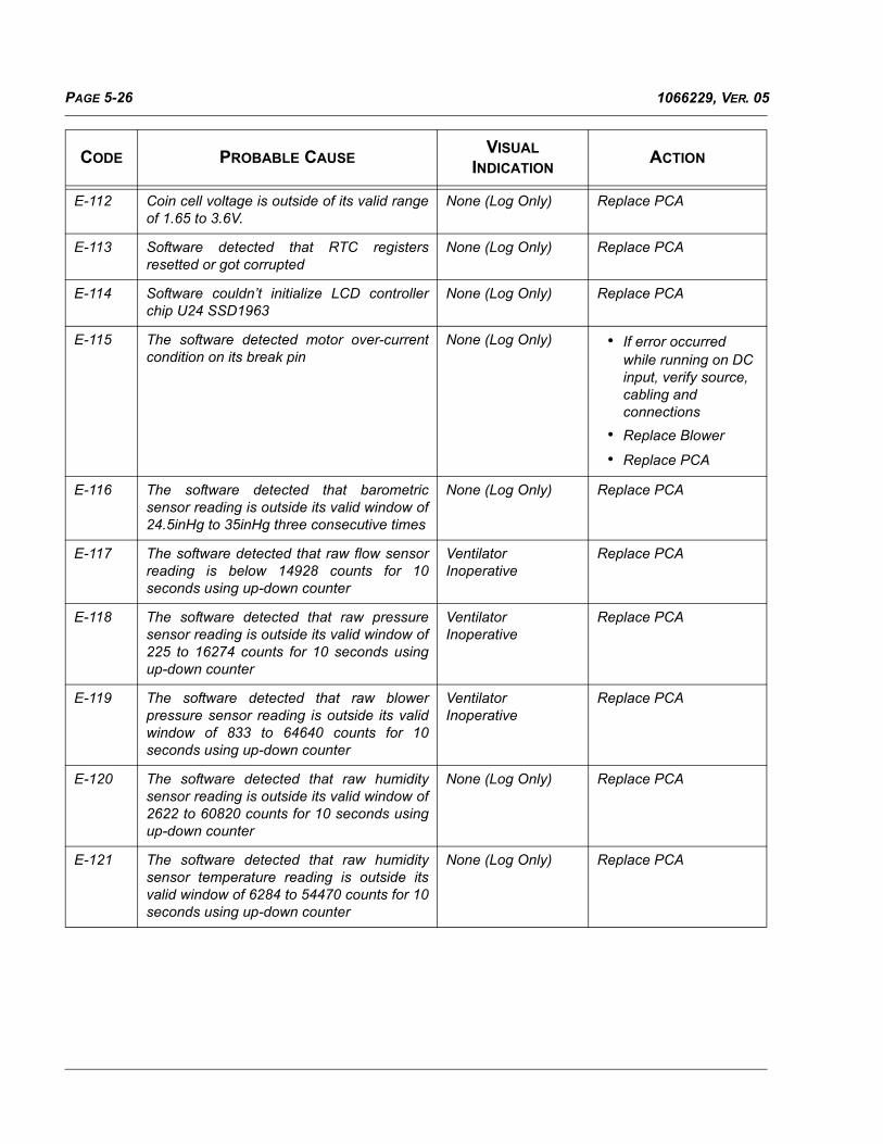
E-112 Coin cell voltage is outside of its valid rangeof 1.65 to 3.6V.
None (Log Only) Replace PCA
E-113 Software detected that RTC registersresetted or got corrupted
None (Log Only) Replace PCA
E-114 Software couldn’t initialize LCD controllerchip U24 SSD1963
None (Log Only) Replace PCA
E-115 The software detected motor over-currentcondition on its break pin
None (Log Only) • If error occurred while running on DC input, verify source, cabling and connections
• Replace Blower
• Replace PCA
E-116 The software detected that barometricsensor reading is outside its valid window of24.5inHg to 35inHg three consecutive times
None (Log Only) Replace PCA
E-117 The software detected that raw flow sensorreading is below 14928 counts for 10seconds using up-down counter
VentilatorInoperative
Replace PCA
E-118 The software detected that raw pressuresensor reading is outside its valid window of225 to 16274 counts for 10 seconds usingup-down counter
VentilatorInoperative
Replace PCA
E-119 The software detected that raw blowerpressure sensor reading is outside its validwindow of 833 to 64640 counts for 10seconds using up-down counter
VentilatorInoperative
Replace PCA
E-120 The software detected that raw humiditysensor reading is outside its valid window of2622 to 60820 counts for 10 seconds usingup-down counter
None (Log Only) Replace PCA
E-121 The software detected that raw humiditysensor temperature reading is outside itsvalid window of 6284 to 54470 counts for 10seconds using up-down counter
None (Log Only) Replace PCA
CODE PROBABLE CAUSEVISUAL
INDICATIONACTION

PAGE 5-271066229, VER. 05
E-122(OriginalSeries)
• Unit is not reaching the requestedpressure support, i.e. the differencebetween the requested pressuresupport and the measured patientpressure support is greater than half ofthe of the requested pressure support.
• Low pressure sensor reading
• Large amount of drift
• Pinched/blocked tubing
“Pressure Regulation” High
Priority Alarm
• Check Device and Circuit setup if patient circuit is available.
• Check the tubing (inside and outside the unit) for leaks, kinks, or blockages.
• Replace the PCA and recalibrate
E-122(SilverSeries)
N/A N/A N/A
E-123 • Software does not support newer/olderrevision of HW
• Board revision resistors on PCA aresetup incorrect
VentilatorInoperative
• Reinstall software
• Replace PCA
E-124 Motor state observer failed to converge andresolve the motor speed
None (Log Only) • Replace Blower
• Replace PCA
E-125 Product ID stored in Device CalibrationTable is not recognized by software. Theunrecognized Product ID is recorded as theoptional text for reference.
VentilatorInoperative
• Recalibrate
• Replace PCA
E-126 • Unit not calibrated
• Calibration Table corrupted
None (Log Only) • Recalibrate
• Replace PCA
E-127 • Unit not calibrated
• Calibration Table corrupted
VentilatorInoperative
• Recalibrate
• Replace PCA
E-128 • Unit not calibrated
• Calibration Table corrupted
None (Log Only) • Recalibrate
• Replace PCA
E-129 Engineering Use None (Log Only) None – recorded for informational purposes to indicate that the unit was calibrated.
E-130 Software error:
• Bad table written by Production
• Field Service Calibration Station
None (Log Only) • Recalibrate
• Replace PCA
CODE PROBABLE CAUSEVISUAL
INDICATIONACTION

PAGE 5-28 1066229, VER. 05
E-131 Calibration was performed None (Log Only) None – recorded for informational purposes to indicate that a calibration was performed on this unit by either the Production or Field Service calibration station.
E-132 Queue for messages to the RASPcommand parser is full
System Reboots This error should not occur. No service action is required. If the error is seen repeatedly, replace the PCA.
E-133 Queue for Event Log is full System Reboots This error should not occur. No service action is required. If the error is seen repeatedly, replace the PCA.
E-134 Queue for messages to the User Interface isfull
None (Log Only) This error should not occur. No service action is required. If the error is seen repeatedly, replace the PCA.
E-135 Queue for messages to the User Interface iswithin 10% of being full
None (Log Only) This error should not occur. No service action is required. If the error is seen repeatedly, replace the PCA.
E-136(OriginalSeries)
The software detected persistentovercurrent condition on break input
None (Log Only) Replace PCA
E-136(SilverSeries)
N/A N/A N/A
E-137 Software upgrade process started None (Log Only) None
E-138 Error in communication between humiditysensor and CPU.
None (Log Only) None. Recorded fordebug purpose.
E-139 N/A Not Used N/A
E-140 Unexpected high level of high-priority (e.g.interrupt) activity
System Reboots None. Recorded fordebug purposes.
E-141 Humidifier thermistor is shorted to ground None (Log Only) Replace humidifier
CODE PROBABLE CAUSEVISUAL
INDICATIONACTION

PAGE 5-291066229, VER. 05
E-142 Humidifier is disconnected while it wasturned on or shorted to the power supply
None (Log Only) • Replace humidifier
• Replace PCA
E-143 Humidifier plate reached 95C which is closeto blowing TCO
None (Log Only) Replace PCA
E-144 Error in accessing files/directories on the SDCard.
None (Log Only) Replace PCA
E-145 Error in creating files/directories on the SDCard.
None (Log Only) Replace PCA
E-146 Error in verifying the flash drive format ondevice start up.
None (Log Only) Replace PCA
E-147 LOG queue is full None (Log Only) This error should not occur. No service action is required. If the error is seen repeatedly, replace the PCA.
E-148 Error in creating the Encore directorystructure on the SD Card.
“Card Error”InformationalMessage
• Use new card.
• Replace PCA
E-149 Error in accessing files/directories on the SDCard.
“Card Error”InformationalMessage
• Use new card.
• Replace PCA
E-150 Program Execution Error None (Log Only) This error should notoccur. No service actionis required. If the error isseen repeatedly, replacethe PCA.
E-151 N/A Not Used N/A
E-152 • Incorrect wattage Power Supplyconnected,
• Faulty AC-DC input connector,
• AC Power Supply fault,
• PCA fault,
• A/D channel fault
“Check AC PowerSupply”InformationalMessage
• Connect correct wattage Power Supply
• Replace AC power Supply
• Replace PCA
E-153 If usable Rx found on the SD Card for thedevice.
None (Log Only) None – recorded for informational purposes to indicate that a valid prescription file was found on the SD card.
CODE PROBABLE CAUSEVISUAL
INDICATIONACTION

PAGE 5-30 1066229, VER. 05
E-154 Rx from the SD Card is ready for userreview.
Prescription reviewscreen displayed attime of Rx Update
None – recorded for informational purposes that the prescription was read successfully from the SD card.
E-155 Failure to update the Rx due to the errors inthe Rx Settings.
“Prescription Change Failed” dialogue box presented to user at time of Rx Update
None – recorded for informational purposes to indicate that the prescription had bad settings.
E-156 Rx update is complete. “Prescription Change Complete” dialogue box presented to user at time of Rx Update
None – recorded for informational purposes to indicate that the prescription update was completed successfully.
E-157 Rx update is canceled by the user by eitherUI option or by pulling out of the card beforeRx Update is complete.
“Prescription Change Canceled” dialogue box presented to user at time of Rx Update
None – recorded for informational purposes to indicate that the prescription update was not completed.
E-158 Failure to update the Rx due to the error inthe file format or errors in reading the file.
“Prescription Change Failed” dialogue box presented to user at time of Rx Update
None – recorded for informational purposes to indicate that the prescription data on the card could not be read.
E-159 Rx version incorrect for the device. “Prescription Change Failed” dialogue box presented to user at time of Rx Update
None – recorded for informational purposes to indicate that the version of the prescription data on the SD card was bad.
E-160 Rx file checksum is incorrect. “Prescription Change Failed” dialogue box presented to user at time of Rx Update
None – recorded for informational purposes to indicate that the prescription on the SD card had a bad checksum.
E-161 When the device encounters errors while ithas started to apply the Rx Setting from theSD Card, the device stops the Rx updateand tries to restore back the old setting onthe device. During the restoration of theseold settings of the device, if there is an errorthen this gets generated.
VentilatorInoperative
Replace PCA
CODE PROBABLE CAUSEVISUAL
INDICATIONACTION

PAGE 5-311066229, VER. 05
E-162 Motor temperature reached 120C. None (Log Only) Replace Blower
E-163 When the device encounters errors while itis copying data from Serial Flash to the SDCard.
“Serial Flash to SD Card Error”
Informational Message
• Use new card.
• Replace PCA.
E-164 Error in opening files/directories on the SDCard.
“Card Error” Informational
Message
• Use new card
• Replace PCA
E-165 Error in write to files/directories on the SDCard.
“Card Error” Informational
Message
• Use new card
• Replace PCA
E-166 Generic informational debug message None (Log only) None – recorded forinformational purposesto track the progress ofcopying data from SerialFlash to the SD Card.
E-167 Debug message indicating that RTC failedto enter initialization mode
None (Log only) None
E-168 Debug message indicating that RTC failedto synchronize date and time register
None (Log only) None
E-169 Debug message indicating that LCDbecame inactive probably due to the ESDevent
None (Log only) None
E-170 When a request to “Write Event Log to SDCard” occurs
None (Log only) None – recorded forinformational purposesto indicate that a requestto write the Event Log tothe SD Card hasoccurred.
E-171 When a request to “Write Event Log to SDCard” fails
None (Log only) None – recorded forinformational purposesto indicate that a requestto write the Event Log tothe SD Card has failed.
E-172 When a request to “Write Event Log to SDCard” completes
None (Log only) None – recorded forinformational purposesto indicate that a requestto write the Event Log tothe SD Card hascompleted.
CODE PROBABLE CAUSEVISUAL
INDICATIONACTION
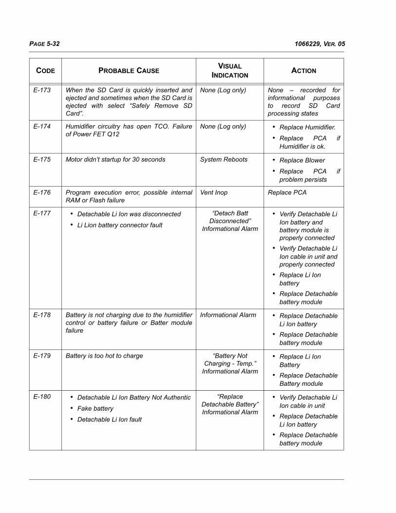
PAGE 5-32 1066229, VER. 05
E-173 When the SD Card is quickly inserted andejected and sometimes when the SD Card isejected with select “Safely Remove SDCard”.
None (Log only) None – recorded forinformational purposesto record SD Cardprocessing states
E-174 Humidifier circuitry has open TCO. Failureof Power FET Q12
None (Log only) • Replace Humidifier.
• Replace PCA ifHumidifier is ok.
E-175 Motor didn’t startup for 30 seconds System Reboots • Replace Blower
• Replace PCA ifproblem persists
E-176 Program execution error, possible internalRAM or Flash failure
Vent Inop Replace PCA
E-177 • Detachable Li Ion was disconnected
• Li Lion battery connector fault
“Detach Batt Disconnected”
Informational Alarm
• Verify Detachable Li Ion battery and battery module is properly connected
• Verify Detachable Li Ion cable in unit and properly connected
• Replace Li Ion battery
• Replace Detachable battery module
E-178 Battery is not charging due to the humidifiercontrol or battery failure or Batter modulefailure
Informational Alarm • Replace Detachable Li Ion battery
• Replace Detachable battery module
E-179 Battery is too hot to charge “Battery Not Charging - Temp.”
Informational Alarm
• Replace Li Ion Battery
• Replace Detachable Battery module
E-180 • Detachable Li Ion Battery Not Authentic
• Fake battery
• Detachable Li Ion fault
“Replace Detachable Battery” Informational Alarm
• Verify Detachable Li Ion cable in unit
• Replace Detachable Li Ion battery
• Replace Detachable battery module
CODE PROBABLE CAUSEVISUAL
INDICATIONACTION
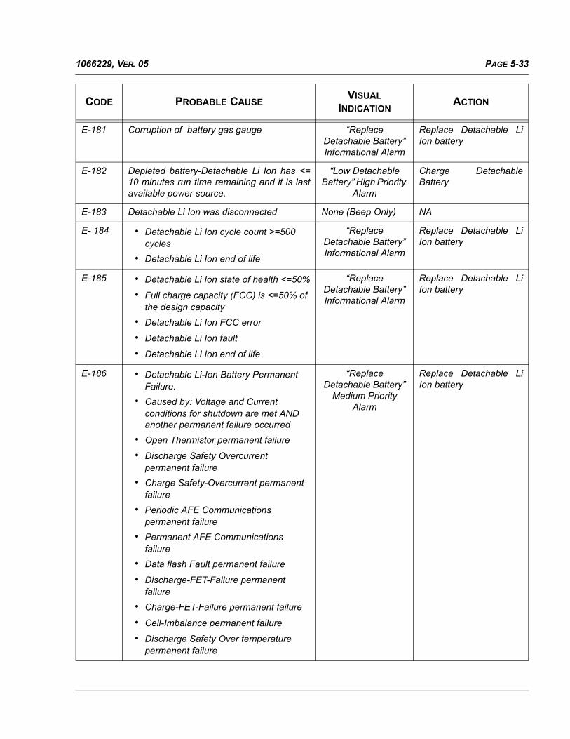
PAGE 5-331066229, VER. 05
E-181 Corruption of battery gas gauge “Replace Detachable Battery” Informational Alarm
Replace Detachable LiIon battery
E-182 Depleted battery-Detachable Li Ion has <=10 minutes run time remaining and it is lastavailable power source.
“Low Detachable Battery” High Priority
Alarm
Charge DetachableBattery
E-183 Detachable Li Ion was disconnected None (Beep Only) NA
E- 184 • Detachable Li Ion cycle count >=500 cycles
• Detachable Li Ion end of life
“Replace Detachable Battery” Informational Alarm
Replace Detachable LiIon battery
E-185 • Detachable Li Ion state of health <=50%
• Full charge capacity (FCC) is <=50% of the design capacity
• Detachable Li Ion FCC error
• Detachable Li Ion fault
• Detachable Li Ion end of life
“Replace Detachable Battery” Informational Alarm
Replace Detachable LiIon battery
E-186 • Detachable Li-Ion Battery Permanent Failure.
• Caused by: Voltage and Current conditions for shutdown are met AND another permanent failure occurred
• Open Thermistor permanent failure
• Discharge Safety Overcurrent permanent failure
• Charge Safety-Overcurrent permanent failure
• Periodic AFE Communications permanent failure
• Permanent AFE Communications failure
• Data flash Fault permanent failure
• Discharge-FET-Failure permanent failure
• Charge-FET-Failure permanent failure
• Cell-Imbalance permanent failure
• Discharge Safety Over temperature permanent failure
“Replace Detachable Battery”
Medium Priority Alarm
Replace Detachable LiIon battery
CODE PROBABLE CAUSEVISUAL
INDICATIONACTION

PAGE 5-34 1066229, VER. 05
E-187 Detachable Battery reported an OverCurrent Discharge or Short CircuitDischarge fault
“Replace Detachable Battery” Informational Alarm
• Check/Replace Detachable Li Ion cable in unit
• Replace Detachable Li Ion battery
• Replace Detachable Battery Module
• Replace PCA
E-188 • Detachable Li Ion cell voltage less than 2.5 volts for greater than 2 sec.
• Battery discharge FET is turned off.
• Battery discharged too low. Battery recovers if cell voltage is greater than 3 volts.
Log Only • Charge Detachable Li Ion battery.
E-189 • Detachable Li Ion cell voltage less than 10 volts for greater than 6 sec.
• Battery discharge FET is turned off.
• Battery discharged too low. Battery recovers if cell voltage is greater than 12 volts.
Log Only • Charge Detachable Li Ion battery
E-190 Battery temperature is >= 60? duringdischarge. Battery recovers if temperatureis less than 55? C.
“Batt Discharge Stopped-Temp”
Informational Alarm
• Allow battery to cool to less than 55? and test that the battery will discharge
• Replace battery if no discharge
E-191 • Detachable Li Ion cell voltage greater than 4.3 volts for greater than 2 sec.
• Battery charge FET is turned off.
• Battery charged too high. Battery recovers if cell voltage is less than 4.1 volts.
Log Only • Replace Detachable Li Ion Battery
• Replace Detachable Battery Module
E-192 • Detachable Li Ion battery Remaining Capacity is 1000 mAh greater than the Full Charge Capacity during charging.
• Battery charged too high.
• Battery recovers if discharged so that Capacity < 95%.
Log Only • Replace Detachable Li Ion Battery
• Replace Detachable Battery Module
CODE PROBABLE CAUSEVISUAL
INDICATIONACTION
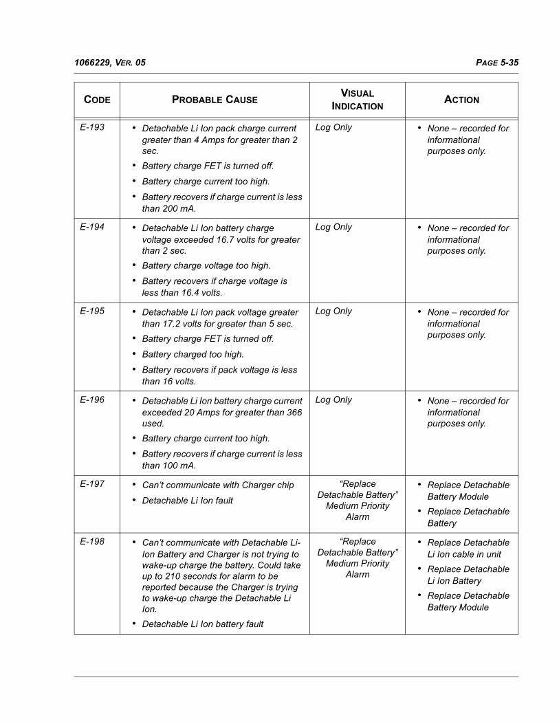
PAGE 5-351066229, VER. 05
E-193 • Detachable Li Ion pack charge current greater than 4 Amps for greater than 2 sec.
• Battery charge FET is turned off.
• Battery charge current too high.
• Battery recovers if charge current is less than 200 mA.
Log Only • None – recorded for informational purposes only.
E-194 • Detachable Li Ion battery charge voltage exceeded 16.7 volts for greater than 2 sec.
• Battery charge voltage too high.
• Battery recovers if charge voltage is less than 16.4 volts.
Log Only • None – recorded for informational purposes only.
E-195 • Detachable Li Ion pack voltage greater than 17.2 volts for greater than 5 sec.
• Battery charge FET is turned off.
• Battery charged too high.
• Battery recovers if pack voltage is less than 16 volts.
Log Only • None – recorded for informational purposes only.
E-196 • Detachable Li Ion battery charge current exceeded 20 Amps for greater than 366 used.
• Battery charge current too high.
• Battery recovers if charge current is less than 100 mA.
Log Only • None – recorded for informational purposes only.
E-197 • Can’t communicate with Charger chip
• Detachable Li Ion fault
“Replace Detachable Battery”
Medium Priority Alarm
• Replace Detachable Battery Module
• Replace Detachable Battery
E-198 • Can’t communicate with Detachable Li-Ion Battery and Charger is not trying to wake-up charge the battery. Could take up to 210 seconds for alarm to be reported because the Charger is trying to wake-up charge the Detachable Li Ion.
• Detachable Li Ion battery fault
“Replace Detachable Battery”
Medium Priority Alarm
• Replace Detachable Li Ion cable in unit
• Replace Detachable Li Ion Battery
• Replace Detachable Battery Module
CODE PROBABLE CAUSEVISUAL
INDICATIONACTION

PAGE 5-36 1066229, VER. 05
E-199 • Environmental conditions
• Motor temperature exceeded 125° C or battery temperature reached 55° C
High Priority Alarm • Verify noenvironmentalconditions exist thatcaused High Tempissue
• Replace Blower
• Allow battery to coolto less than 55° Cand test that thebattery willdischarge. Replacebattery if nodischarge
E-200 Low battery - Detachable Li Ion has <= 20Minutes run time remaining and it is lastavailable power source.
“Low Detachable Battery” Medium
Priority Alarm
• Charge DetachableLi Ion battery
E-201 Clear Patient Data is Requested Info Alarm None
E-202 Clear Patient Data failed due to bad SDCard or PCA
Info Alarm • Replace SD Card
• Replace PCA
E-203 Clear patient data is completed Info Alarm None
E-204 This is debug error code for MMC SD driverthat records general SD card information(e.g. Manufacture, capacity, etc.) as well asnumber of failed write/read retries.
Log Only None
E-205 The charger has failed in trying to wake-upcharge the battery after ~210 seconds.
“Replace Detachable Battery” Medium Priority Alarm
Test Battery Module byusing another battery. Iferror still reported thenreplace the batterymodule; if error notreported then replaceDetachable Li Ion Battery
E-206 PIC processor or associated circuitry failure Vent Inop Replace PCA
E-207(OriginalSeries)
Outlet Pressure Sensor is reading less than0.75cm for 3 seconds NOTE- this error processing is not active inCal Mode
“Pressure Regulation” High Priority Alarm
• Check the tubing(inside and outsidethe unit) for leaks.
• Check the manifoldbetween the Sensorson PCA and Flowsensor Assy
• Replace the PCAand recalibrate.
CODE PROBABLE CAUSEVISUAL
INDICATIONACTION

PAGE 5-371066229, VER. 05
E-207(SilverSeries)
N/A N/A N/A
E-208(OriginalSeries)
Firmware Version 2.3 and before - Programexecution errorFirmware Version greater than 2.3 - N/A
System Reboot
N/A
None
E-208(SilverSeries)
This alarm is generated if the BlowerPressure is >= cmH2O for >= 3 sec.
VENT_INOP Replace PCA
E-209(OriginalSeries)
N/A N/A N/A
E-209(SilverSeries)
Ventilator did not enter sleep state within ten seconds after sleep command was executed
None (Log Only) None
E-210(OriginalSeries)
N/A N/A N/A
E-210(SilverSeries)
Power management thread called before the first call to measure
None (Log Only) None
E-211(OriginalSeries)
N/A N/A N/A
E-211(SilverSeries)
Heated Tube Thermistor is shorted. None (Log Only) Replace PCA
E-212(OriginalSeries)
N/A N/A N/A
E-212(SilverSeries)
Heated Tube Thermistor is open None (Log Only) Replace PCA
E-213(OriginalSeries)
N/A N/A N/A
E-213(SilverSeries)
Li Ion Battery Fuse Open Medium Priority Alarm
Replace Li Ion Battery
E214 Defective EEPROM System Reboots Replace PCA
CODE PROBABLE CAUSEVISUAL
INDICATIONACTION

PAGE 5-38 1066229, VER. 05
5.5 FSA TEST STATION ERROR CODES
This section contains the common errors associated with the various FSA Test Station processes.
ERROR CODES 5100 TO 5999 SYSTEM DEFINED ERRORS
ERROR CODES 6000 TO 6999 RASP/COMMUNICATION ERRORS
E-999(OriginalSeries)
Program Execution Error None (Log Only) None
999(SilverSeries)
A write to the Event Log did not completesuccessfully
System Reboot None
E-65535 A write to the Event Log did not completesuccessfully.
None (Log Only) None
CODE PROBABLE CAUSE CORRECTIVE ACTION
5103 Pressure unstable Check all connections with equipmentand unit and RETEST Unit
5104 Flow unstable. Check all connections with equipmentand unit and RETEST Unit
5105 Pressure Reading Failure. Check all connections with equipmentand unit and RETEST Unit
CODE PROBABLE CAUSE CORRECTIVE ACTION
6001 No reply received. Communicationprotocol violation
Check all connections with equipmentand unit and RETEST Unit
6002 Message not accepted or interface notsupported.
Check all connections with equipmentand unit and RETEST Unit
6003 Timeout: no message available orincomplete message.
Check serial cable and power to the unit.
CODE PROBABLE CAUSEVISUAL
INDICATIONACTION

PAGE 5-391066229, VER. 05
ERROR CODES 7103 TO 7110 TSI COMMUNICATION ERRORS
ERROR CODES 9001 TO 9050 FSA TEST STATION ERRORS
CODE PROBABLE CAUSE CORRECTIVE ACTION
7104 TSI 4000 Series: could not complete Read operation
Reboot PC and power cycle the TSI 4000
7105 TSI 4000 Series: Init command must be run before using others driver's commands.
Reboot PC and power cycle the TSI 4000
7106 TSI 4000 Series: there is no commandacknowledge returned
Reboot PC and power cycle the TSI 4000
7107 TSI 4000 Series: device returned aninternal error
Reboot PC and power cycle the TSI 4000
7108 TSI 4000 Series: device returned invalidmeasurements
Reboot PC and power cycle the TSI 4000
CODE PROBABLE CAUSE CORRECTIVE ACTION
9001 Zero reference flow is out of theallowable limits.
Make sure that all of the hoses areconnected/disconnected as instructed
9002 Unknown A30/40 Cal table ID. Verify unit SN/MN Label to the UUT.
9003 The RASP device ID was found to beinvalid when creating the Device table.
Verify unit SN/MN Label to the UUT.
9004 Time out occurred because the flowsetpoint was not achieved in the allowedtime frame during flow calibration or flowverification.
Check the tubing connections and verifythat there are no air leaks
9005 Time out occurred because the pressuresetpoint was not achieved in the allowedtime frame during pressure calibration,pressure verification or max pressuretest.
Check the tubing connections and verifythat there are no air leaks
9006 UUT pressure or flow is not stable Check the tubing connections and verifythat there are no air leaks
9007 Time out occurred because the RPMsetpoint was not achieved in the allowedtime frame.
Check the tubing connections and verifythat there are no air leaks
9008 UUT blower failed to start withinexpected time.
Check the tubing connections and verifythat there are no air leaks
9009 Minimum flow required for this test wasnot achieved.
Check the tubing connections and verifythat there are no air leaks

PAGE 5-40 1066229, VER. 05
9010 The S/N prefix is invalid for this DeviceID.
Verify unit SN/MN Label to the UUT.
9011 The S/N CRC does not match thecalculated one.
Verify unit SN/MN Label to the UUT.
9012 The S/N length is invalid. Verify unit SN/MN Label to the UUT.
9013 An unknown or no power source wasdetected.
Verify all applicable Power Sources andthe Serial interface are properlyconnected to the UUT & test setup
9014 The model number from barcode wasnot found in the models lookup table.
Verify unit SN/MN Label to the UUT.
CODE PROBABLE CAUSE CORRECTIVE ACTION
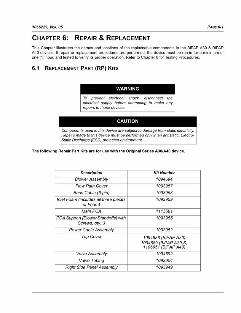
PAGE 6-11066229, VER. 05
CHAPTER 6: REPAIR & REPLACEMENT
This Chapter illustrates the names and locations of the replaceable components in the BiPAP A30 & BiPAPA40 devices. If repair or replacement procedures are performed, the device must be run-in for a minimum ofone (1) hour, and tested to verify its proper operation. Refer to Chapter 8 for Testing Procedures.
6.1 REPLACEMENT PART (RP) KITS
The following Repair Part Kits are for use with the Original Series A30/A40 device.
WARNING
To prevent electrical shock, disconnect theelectrical supply before attempting to make anyrepairs to these devices.
CAUTION
Components used in this device are subject to damage from static electricity.Repairs made to this device must be performed only in an antistatic, Electro-Static Discharge (ESD) protected environment.
Description Kit Number
Blower Assembly 1094694
Flow Path Cover 1093957
Base Cable (6-pin) 1093953
Inlet Foam (includes all three pieces of Foam)
1093959
Main PCA 1115581
PCA Support (Blower Standoffs) with Screws, qty. 3
1093955
Power Cable Assembly 1093952
Top Cover 1094688 (BiPAP A30)1094689 (BiPAP A30-S)1106951 (BiPAP A40)
Valve Assembly 1094692
Valve Tubing 1093954
Right Side Panel Assembly 1093949
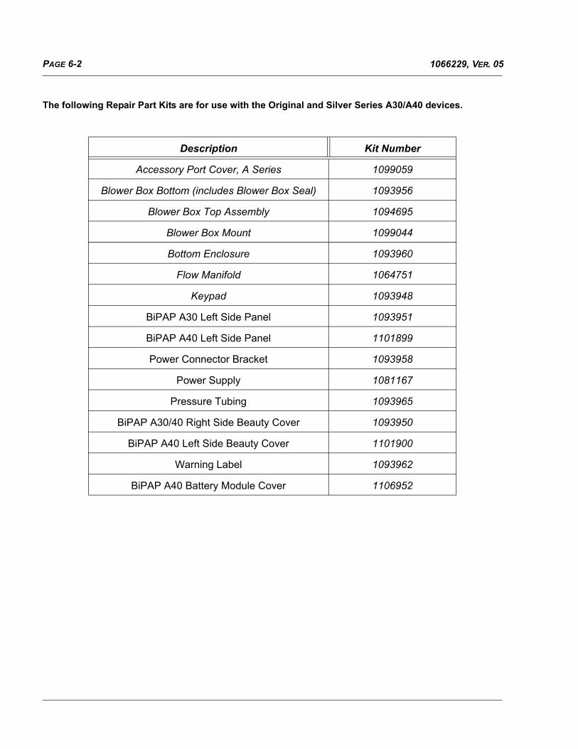
PAGE 6-2 1066229, VER. 05
The following Repair Part Kits are for use with the Original and Silver Series A30/A40 devices.
Description Kit Number
Accessory Port Cover, A Series 1099059
Blower Box Bottom (includes Blower Box Seal) 1093956
Blower Box Top Assembly 1094695
Blower Box Mount 1099044
Bottom Enclosure 1093960
Flow Manifold 1064751
Keypad 1093948
BiPAP A30 Left Side Panel 1093951
BiPAP A40 Left Side Panel 1101899
Power Connector Bracket 1093958
Power Supply 1081167
Pressure Tubing 1093965
BiPAP A30/40 Right Side Beauty Cover 1093950
BiPAP A40 Left Side Beauty Cover 1101900
Warning Label 1093962
BiPAP A40 Battery Module Cover 1106952

PAGE 6-31066229, VER. 05
The following Repair Part Kits are for use with the Silver Series A30/A40 device.
Description Kit Number
Six Pin Harness 1114063
Main PCA 1114064
Blower Kit 1114065
A40 Top Cover 1114066
A30 Top Cover 1114067
A30-S Top Cover 1114068
BiPAP SOH Top Cover 1117844
PCA Support 1114070
Outlet Flow Path 1114071
Heated Hose, Right Side Assy 1114072
Flow Path Cover 1114073
Power Cable Harness 1114074
Inlet Foam Kit 1114075
Blower Box Seal 1114076
BiPAP SOH Keypad 1119924
BiPAP SOH UI Panel 1116473
A30 UI Panel 1117841
A40 UI Panel 1117842
A30-S UI Panel 1117843

PAGE 6-4 1066229, VER. 05
6.2 BASE UNIT PRELIMINARY CHECKOUT
Prior to performing repair and replacement procedures on the device:
1. Visually inspect the outside of the device for physical damage and broken or missing parts.
2. Apply power to the device and verify the buttons are properly back-lit and the LCD is working.
3. Install a 1/4” Test orifice on the device’s outlet port.
4. Turn on the device and verify proper operation. Listen to the device for noisy operation or loose components.
5. View the device’s error/event/alarm log. Refer to Chapter 5.
6. Perform repairs to the device as necessary.

PAGE 6-51066229, VER. 05
6.3 REPLACEMENT INSTRUCTIONS
6.3.1 REPLACING THE ACCESSORY PORT COVER, A SERIES
FIGURE 6-1: ACCESSORY PORT COVER LOCATION
TO REMOVE THE ACCESSORY PORT COVER, A SERIES:
• Use a flat screwdriver and gently pry the Accessory Port Cover away from the device.
TO INSTALL THE ACCESSORY PORT COVER, A SERIES:
• Snap the SD Card Slot Cover into place on the back of the device.
Included in Kit Tools Required Part Number(s)
Accessory Port Cover, A Series Small flat blade screwdriver 1099059

PAGE 6-6 1066229, VER. 05
6.3.2 REPLACING THE RIGHT SIDE COVER
TO REMOVE THE RIGHT SIDE COVER
1. Push the locking tab on the end of the Right Side Cover towards the device’s Outlet Port.
2. Lift the Cover away from the device.
FIGURE 6-2: RIGHT SIDE COVER LOCKING TAB
TO REMOVE THE RIGHT SIDE COVER
1. Insert the Right Side Cover, support tabs at the front of the device first, into it’s mounting location.
2. Press the Right Side Cover fully into place. Verify that the locking tab snaps and secures the cover.
Included in Kit Tools Required Part Number(s)
Right Side Cover None 1093949
1114072
NOTE
The Right Side Cover is used when there is noHumidifier present.

PAGE 6-71066229, VER. 05
6.3.3 REPLACING THE USER INTERFACE PANEL
TO REMOVE THE USER INTERFACE PANEL
1. Gently peel back the User Interface Panel from the Top Cover
2. Remove any residual adhesive from the Top Cover.
Included in Kit Tools Required Part Number(s)
User Interface Panel N/A 1116473 / 1117841
1117842 / 1117843

PAGE 6-8 1066229, VER. 05
TO INSTALL THE USER INTERFACE PANEL
1. Remove the protective backing from the new User Interface Panel
2. Install the User Interface Panel to the Top Cover ensuring the Panel fits within the recessed area.
FIGURE 6-3 GOOD UI PANEL INSTALL
FIGURE 6-4 BAD UI PANEL INSTALL
GOOD
BAD

PAGE 6-91066229, VER. 05
6.3.4 REPLACING THE TOP COVER
FIGURE 6-5: TOP COVER
TO REMOVE THE TOP COVER
1. Place the device on a protected work surface and carefully turn it over to expose its bottom.
2. Remove the SD Card if one is installed.
3. Using a Torx T15 screwdriver, remove the four (4) screws that secure the Top Cover to the Bottom Enclosure. Refer to Figure 6-6.
4. While securely holding the device together, carefully return it to its upright position.
5. Lift the Top Cover away from the Bottom Enclosure. The SD Card Slot Cover is loosely installed in the Top Cover.
6. The Keypad has a tendency to remain in the Top Cover. If necessary, remove the Keypad from the Top Cover and maintain it for installation in the replacement Top Cover.
Included in Kit Tools Required Part Number(s)
Top Cover T15 Torx screwdriver 1094688 / 1094689
1106951 / 1114066
1114067 / 1114070

PAGE 6-10 1066229, VER. 05
FIGURE 6-6: SCREW LOCATION
To install the Top Cover:
1. Place the Top Cover onto the Bottom Enclosure.
2. Hold the device together and turn it over to expose its bottom.
3. Secure the Top Cover to the Bottom Enclosure using the four (4) #6-19 X 9/16” screws. Torque screws to 13 in-lbs.
4. Assemble the remainder of the device as instructed in previous sections.
NOTE
The Accessory Module Port Cover is loosely installed inthe Top Cover. Use care when removing the Top Cover soas not to lose the Accessory Module Port Cover.

PAGE 6-111066229, VER. 05
6.3.5 REPLACING THE KEYPAD
FIGURE 6-7: KEYPAD
To remove the Keypad:
1. Remove the Top Cover. Refer to Replacing the Top Cover.
2. Remove the Keypad from the Top Cover.
To install the Keypad:
1. Place the Keypad in the Top Cover.
2. Assemble the remainder of the device as instructed in previous sections.
Included in Kit Tools Required Part Number(s)
Keypad T15 Torx screwdriver 1093948
1119924
CAUTION
Damage to the PCA may occur if the Keypad is not properly aligned and installed.
Be sure to properly orient the Keypad during installation.
The vertical line on the On/Off button should be parallel with
the side of the device.

PAGE 6-12 1066229, VER. 05
6.3.6 REPLACING THE LEFT SIDE PANEL
FIGURE 6-8: OUTSIDE COVER REMOVAL
To remove the Left Side Panel:
1. Remove the Top Cover. Refer to Replacing the Top Cover. For BiPAP A30 devices proceed to step 3.
Included in Kit Tools Required Part Number(s)
End Panel T15 Torx screwdriver 1093951
1101899

PAGE 6-131066229, VER. 05
2. For BiPAP A40 devices remove the 6 pin connector from location P2 on the Main PCA.
3. Slide the Left Side Panel out of the Bottom Enclosure.
To Install the Left Side Panel:
1. Slide the Outside Cover into the Bottom Enclosure. For BiPAP A30 devices proceed to step three.
2. For BiPAP A40 devices, connect the six pin connector to location P2 on the Main PCA.
3. Assemble the remainder of the device as instructed in previous sections.

PAGE 6-14 1066229, VER. 05
6.3.7 REPLACING THE MAIN PCA
FIGURE 6-9: MAIN PCA
To remove the Main PCA:
1. Remove the Top Cover. Refer to Replacing the Top Cover.
2. Disconnect the wiring harnesses from the Main PCA. The wiring harnesses are indicated by the arrows in Figure 6-9. The Black Arrows represent connection for both the BiPAP A30 and BiPAP A40 devices and the white arrow showing an additional connection on the BiPAP A40 devices.
Included in Kit Tools Required Part Number(s)
Main PCA T15 Torx screwdriver 1115581
1114064
CAUTION
A piece of Tubing is connected to the PCA. Tilt the PCA to access theconnection of the Tubing before fully lifting the PCA out of the BottomEnclosure.
BiPAP A40 Connection Only

PAGE 6-151066229, VER. 05
3. Disconnect the Tubing from the underside of the PCA. Refer to Figure 6-9.
4. Lift the PCA out of the Bottom Enclosure.
To Install the Main PCA:
1. Place the PCA in the Bottom Enclosure. Be sure that the Flow and Pressure Sensors properly align with the Flow Manifold.
FIGURE 6-10: ALIGN SENSOR PORTS ON PCA WITH MANIFOLD
2. Connect the blue Pressure Tubing to the Main PCA.
3. Connect the wiring harnesses to the PCA.
4. Assemble the remainder of the device as instructed in previous sections.
CAUTION
The PCA’s Flow and Pressure Sensors must be in proper alignment withthe Flow Manifold. Otherwise, the device will not operate properly.
CAUTION
When seating the PCA, be sure the ferrite on the Blower Wiring Harnessis seated against the device’s Right Side Panel.
CAUTION
During installation of internal components, be sure all tubing connectionsare secure, not pinched, folded under, etc. to ensure proper operation ofthe device.

PAGE 6-16 1066229, VER. 05
NOTE
Once you have removed the PCA, the components referred to inReplacing the Blower, Blower Box, and/or PCA Supports throughReplacing the Right Panel Assembly can be removed in any order.

PAGE 6-171066229, VER. 05
6.3.8 REPLACING THE BLOWER, BLOWER BOX, AND/OR PCA SUPPORTS
FIGURE 6-11: BLOWER REMOVAL
Included in Blower Kit Tools Required Part Number(s)
Blower
Blower Mount (x3)
T10 Torx screwdriver
T15 Torx screwdriver
1114065
1094694
Included in the two (2) Blower Box Kits Tools Required
Blower Box Top includes:
• Blower Box Top
• Blower Cap Bumper
• #4-40 x 1/2” screws (x6)Blower Box Bottom includes:
• Blower Box Bottom
• Blower Box Seal
T10 Torx screwdriver
T15 Torx screwdriver

PAGE 6-18 1066229, VER. 05
To remove the Blower Box
1. Remove the Top Cover. Refer to Replacing the Top Cover.
2. Remove the Main PCA. Refer to Replacing the Main PCA.
3. Using a T15 Torx screwdriver, remove the three screws that secure the PCA Supports to the Bot-tom Enclosure.
4. Disconnect the Valve Inlet Elbow from the Blower Outlet. (Original Series ONLY)
5. Using caution so as not to damage the Blower Box Mount (see caution box below), lift the Blower Box out of the Bottom Enclosure. Note that the Blower Box Seal is located between the Blower Inlet (located on the Bottom of the Blower Box) and the Foam Inlet Cover.
FIGURE 6-12: BLOWER BOX SEAL
CAUTION
Three grommets protrude from inside the Blower Box (zinc casting) and are located in the PCA Support cutouts. Use caution when lifting the Blower Box (with Blower) out of the Bottom Enclosure so as not to cause damage. These grommets are part of the Blower Box Mount, as shown here (RP Kit #1099044).

PAGE 6-191066229, VER. 05
6. Using a T10 Torx screwdriver, remove the six (6) screws that secure the Blower Box Top to the Blower Box Bottom.
FIGURE 6-13: BLOWER BOX SCREW LOCATION
7. Lift the Blower Assembly out of the Blower Box.
FIGURE 6-14: BLOWER IN BLOWER BOX BOTTOM
Three (3) Blower Mounts are included in The
Blower Assembly RP Kit.

PAGE 6-20 1066229, VER. 05
To install the Blower Assembly:
1. Place the Blower Assembly with Blower Mounts into the Blower Box Bottom as shown previously in Figure 6-14.Verify that the Blower Mounts and Blower Box Mounts are correctly seated in the Blower Box Bottom.
2. Route the Blower Wiring Harness through the cutout in the Blower Box Top and situate the grom-met appropriately.
FIGURE 6-15: PROPER SEATING OF GROMMET
3. Secure the Blower Box Top to the Blower Box Bottom using the six (6) #4-40 x 1/2” screws. Torque screws to 7 in.-lbs.
4. Verify that the Blower Box Seal is installed in the Bottom Enclosure as shown previous in Figure 6-12.
5. Align the Blower Box Bottom Inlet Port with the Blower Box Seal and place the Blower Box w/Blower Assembly into the Bottom Enclosure.
6. Verify that the Blower Box Mount protruding grommets are aligned with the standoffs in the Bottom Enclosure as shown in
FIGURE 6-16: BLOWER BOX MOUNTING LOCATION
7. Secure the Blower Box w/Blower Assembly to the Bottom Enclosure using the three PCA Sup-ports. Torque the PCA Support Screws to 9 in.-lbs.
8. Assemble the remainder of the device as instructed in previous sections.
Correct Incorrect

PAGE 6-211066229, VER. 05
6.3.9 REPLACING THE VALVE ASSEMBLY
This procedure applies only to the Original Series device Model Numbers:
FIGURE 6-17: VALVE ASSEMBLY
To remove the Valve Assembly:
1. Remove the Top Cover. Refer to Replacing the Top Cover.
2. Remove the Main PCA. Refer to Replacing the Main PCA.
3. Remove the three (3) screws that secure the Valve Assembly to the Bottom Enclosure.
4. Lift the Valve Assembly out of the Bottom Enclosure.
Included in Kit Tools Required Part Number(s)
• Valve Assembly
• 6-19 x 3/8# screws ((x3)
• Flat Washers (x3)
• Grommets (x3)
• T15 Torx screwdriver 1094694

PAGE 6-22 1066229, VER. 05
To install the Valve Assembly:
1. Places the Valve Assembly grommets into the Valve Assembly slots.
2. Secure the Valve to the Foam Path Cover (installed in the Bottom Enclosure) as shown in Figure 6-18. Torque the screws to 5 in.-lbs.
FIGURE 6-18: VALVE INSTALLATION
3. Assemble the remainder of the device as instructed in previous sections.
CAUTION
When installing the Valve Assembly, use a blunt, non-conductive probingtool to prod the silicone pieces and ensure good connections.
CAUTION
Be sure all tubing connections are secure, not pinched, folded under, etc.to ensure proper operation of the device.

PAGE 6-231066229, VER. 05
6.3.10 REPLACING THE OUTLET FLOW PATH
FIGURE 6-19 OUTLET FLOW PATH
To remove the Outlet Flow Path:
1. Remove the Top Cover. Refer to Section 6.2.3.
2. Remove the Main PCA. Refer to Section 6.2.6.
3. Remove the two (2) screws that secure the Outlet Flow Path to the Bottom Enclosure.
4. Lift the Outlet Flow Path out of the Bottom Enclosure.
To install the Outlet Flow Path:
1. Place the Outlet Flow Path on the Valveless Flow Path Cover.
2. Secure the Outlet Flow Path to the Valveless Flow Path Cover (installed in the Bottom Enclosure).
3. Assemble the remainder of the device as instructed in previous sections
Included in Kit Tools Required Part Number(s)
• Flow Path Outlet
• 6-19 x 3/8# screws (x2)
• Flat Washers (x3)3
• T15 Torx screwdriver 1114071

PAGE 6-24 1066229, VER. 05
6.3.11 REPLACING THE FLOW MANIFOLD
To remove the Flow Manifold:
1. Remove the Top Cover. Refer to Replacing the Top Cover.
2. Remove the Main PCA. Refer to Replacing the Main PCA.
3. Lift the Flow Manifold off of the Right Side Assembly.
FIGURE 6-20: FLOW MANIFOLD (INSTALLED)
To install the Flow Manifold:
1. Place the Flow Manifold onto the Right Side Assembly as shown in Figure 6-20. Be sure that the manifold is properly aligned with the ports on the Right Panel Assembly.
2. Assemble the remainder of the device as instructed in previous sections.
Included in Kit Tools Required Part Number(s)
• Flow Manifold • T15 Torx screwdriver 1064751

PAGE 6-251066229, VER. 05
6.3.12 REPLACING THE RIGHT PANEL ASSEMBLY
FIGURE 6-21: RIGHT PANEL ASSEMBLY
To remove the Right Panel Assembly:
1. Remove the Top Cover. Refer to Replacing the Top Cover.
2. Remove the Main PCA. Refer to Replacing the Main PCA.
3. Remove the Flow Manifold. Refer to Replacing the Valve Assembly.
4. Lift the Right Panel Assembly out of the Bottom Enclosure.
To install the Right Panel Assembly:
1. Slide the Right Panel Assembly into the Bottom Enclosure.
2. Place the Flow Manifold onto the Right Panel Assembly as shown previously.
3. Assemble the remainder of the device as instructed in previous sections.
Included in Kit Tools Required Part Number(s)
• Right Side Assembly • T8 Torx screwdriver
• T15 Torx screwdriver
1114072
1093949

PAGE 6-26 1066229, VER. 05
6.3.13 REPLACING THE BASE CABLE (6 PIN)
FIGURE 6-22: BASE CABLE (6 PIN)
To remove the Base Cable (6 pin):
1. Remove the Top Cover. Refer to Replacing the Top Cover.
2. Remove the Main PCA. Refer to Replacing the Main PCA.
3. Remove the Right Panel Assembly. Refer to Replacing the Right Panel Assembly.
To install the Base Cable (6 pin):
1. Place the Base Cable (6 pin) into the Bottom Enclosure. Be sure the Base Cable (6 pin) is properly seated in its mounting location.
2. Assemble the remainder of the device as instructed in previous sections.
Included in Kit Tools Required Part Number(s)
• Base Cable (6 pin) • T8 Torx screwdriver
• T15 Torx screwdriver
1114063
1093953
Verify slot is facing upwards during
installation.
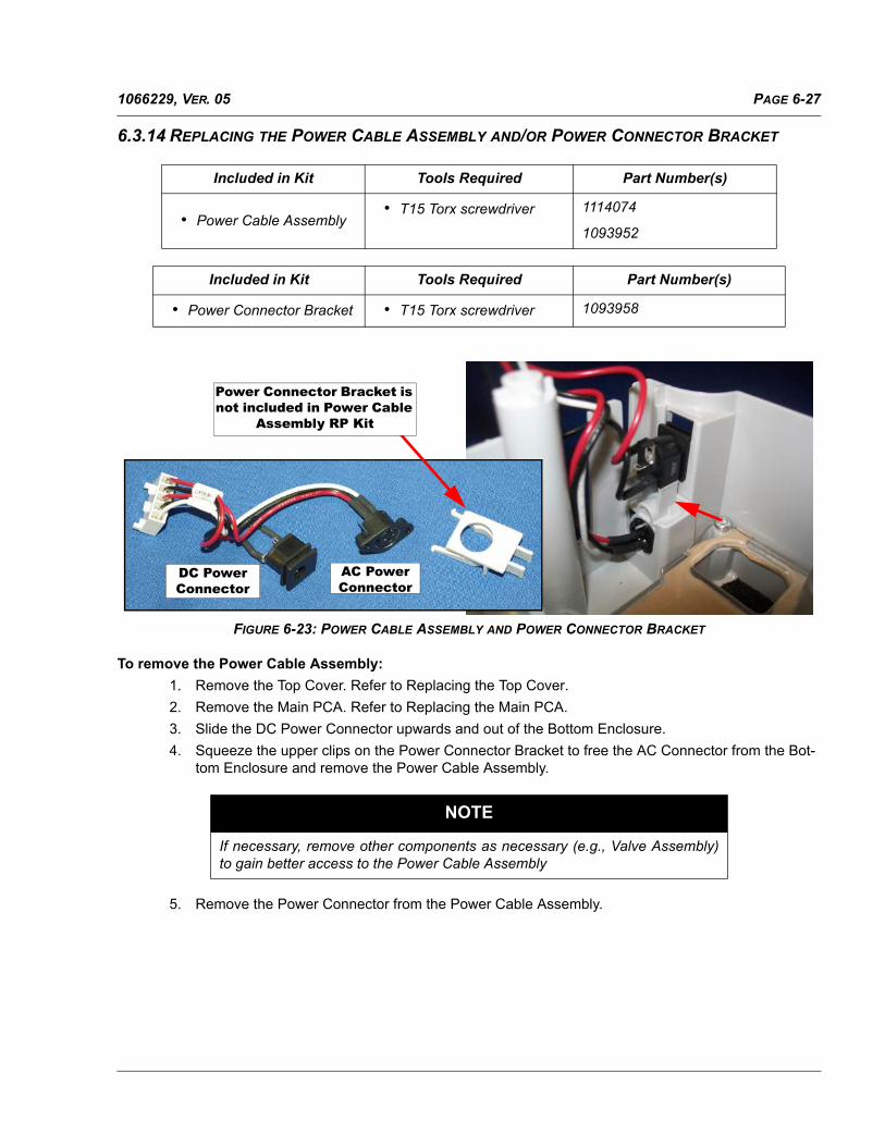
PAGE 6-271066229, VER. 05
6.3.14 REPLACING THE POWER CABLE ASSEMBLY AND/OR POWER CONNECTOR BRACKET
FIGURE 6-23: POWER CABLE ASSEMBLY AND POWER CONNECTOR BRACKET
To remove the Power Cable Assembly:
1. Remove the Top Cover. Refer to Replacing the Top Cover.
2. Remove the Main PCA. Refer to Replacing the Main PCA.
3. Slide the DC Power Connector upwards and out of the Bottom Enclosure.
4. Squeeze the upper clips on the Power Connector Bracket to free the AC Connector from the Bot-tom Enclosure and remove the Power Cable Assembly.
5. Remove the Power Connector from the Power Cable Assembly.
Included in Kit Tools Required Part Number(s)
• Power Cable Assembly• T15 Torx screwdriver 1114074
1093952
Included in Kit Tools Required Part Number(s)
• Power Connector Bracket • T15 Torx screwdriver 1093958
NOTE
If necessary, remove other components as necessary (e.g., Valve Assembly)to gain better access to the Power Cable Assembly
Power Connector Bracket is not included in Power Cable
Assembly RP Kit
DC Power Connector
AC Power Connector

PAGE 6-28 1066229, VER. 05
To install the Power Cable Assembly:
1. Install the Power Connector Bracket onto the AC Connector portion of the Power Cable Assembly.
2. Place the AC Power Connector into its mounting location in the Bottom Enclosure. Be sure that it snaps into place.
3. Slide the DC Power Connector into its mounting location in the Bottom Enclosure.
4. Assemble the remainder of the device as instructed in previous sections.
CAUTION
The Power Cable Assembly wires are shipped unbent. It is necessary toproperly bend the wires so the wires so that the Assembly is properlyseated and the device is assembled properly. Do Not overly bend or twistthe wires so as to cause damage to the wires.

PAGE 6-291066229, VER. 05
6.3.15 REPLACING THE FLOW PATH COVER AND/OR AIR PATH FOAM
This procedure applies only to the following Silver Series device Model Numbers:
FIGURE 6-24: FLOW PATH COVER
TO REMOVE THE FLOW PATH COVER:1. Remove the Top Cover, Main PCA, Blower Assembly in Blower Box, and Valve Assembly as per
previous sections.
2. Remove any additional components impeding access to the Flow Path Cover (e.g., Grommets, Seals, Wiring Harnesses, etc.
3. Remove the nine (9) screws that secure the Flow Path Cover and lift it out of the Bottom Enclo-sure.
Included in Kit Tools Required Part Number(s)
• Flow Path Cover
• 6-19 x 9/16 Screws (x9)
• T8 Torx screwdriver
• T15 Torx screwdriver
1093957 / 1114073
1093959 / 1114075

PAGE 6-30 1066229, VER. 05
4. Lift the Flow Path Cover out of the Bottom Enclosure.
FIGURE 6-25: AIR FOAM PLACEMENT
TO INSTALL THE FLOW PATH COVER:1. Place the Foam in the Bottom Enclosure as shown in Figure 6-24.
2. Assemble the remainder of the device as instructed in previous sections.
NOTE
Observe the placement of the Sound AbatementFoam in the Bottom Enclosure.

PAGE 6-311066229, VER. 05
6.3.16 REPLACING THE BOTTOM ENCLOSURE
FIGURE 6-26: BOTTOM ENCLOSURE
Included in Kit Tools Required Part Number(s)
• Bottom Enclosure
• Warning Label
• T8 Torx screwdriver
• T15 Torx screwdriver
1093960

PAGE 6-32 1066229, VER. 05
This page intentionally blank.

PAGE 7-11066229, VER. 05
CHAPTER 7: HUMIDIFIER REPAIR AND REPLACEMENT
This section illustrates the names and locations of the replaceable components in the System One Humidifier.
7.0 HUMIDIFIER REPLACEMENT PART (RP) KITS
WARNING
To prevent electrical shock, disconnect the Humidifier from theNIV device before attempting to make any repairs.
CAUTION
Components used in this device are subject to damage from static electricity.Repairs made to this device must be performed only in an antistatic, Electro-Static Discharge (ESD) protected environment.
RP KIT NAMEORIGINAL SERIES
PART NUMBER
SILVER SERIES NON-HEATED TUBE
PART NUMBER
SILVER SERIES HEATED TUBE PART NUMBER
Dry Box Assembly 1064803 1064803 1064803
Dry Box Seal (included w/Inlet Seal)
1064804 1064804 1064804
Flip Lid Assembly 1093865 1093865 1114892
Heater Plate 1093867 1093867 1099585
Heater Plate Spring 1064807 1064807 1064807
Humidifier Bottom Housing 1093866 1114891 1114891
Humidifier Lower Base 1094687 1094687 1114890
Humidifier Top Housing 1093966 1093966 1121288
Outside Cover 1064808 1064808 1064808
Slider Docking Latch 1064797 1064797 1064797
Warning Label Int’l 1093964 1093964 1093964
Warning Label Dom U.S. 1093963 1093963 1093963
Water Chamber (Dom.U.S.)
1063785 1063785 1063785
Torx Screwdriver Kit 1040889 1040889 1040889

PAGE 7-2 1066229, VER. 05
7.1 HUMIDIFIER PRELIMINARY CHECKOUT
Prior to performing repair and replacement procedures on the device:
1. Visually inspect the outside of the device for physical damage and broken or missing parts.
2. Connect the Humidifier to the NIV device and verify that the Heater Plate works (i.e., does it get warm?)
3. Perform repairs to the device as necessary.

PAGE 7-31066229, VER. 05
7.2 REPLACEMENT INSTRUCTIONS
Refer to the following sections for information on repairing the BiPAP A30/BiPAP A40 Humidifier.
7.2.1 REPLACING THE WATER CHAMBER ASSEMBLY
FIGURE 7-1: WATER CHAMBER ASSEMBLY
To remove the Water Chamber Assembly:
1. Gently squeeze the latch on the Flip Lid Assembly to release it and lift the Flip Lid Assembly.
2. Pull the Water Chamber Assembly out of the Humidifier.
To Install the Water Chamber Assembly:
1. With the Flip Lid Assembly in the up position, push the Water Chamber Assembly into the Humidi-fier.
2. Be sure the Water Chamber assembly is fully seated with the Dry Box Seal.
3. Close the Flip Lid Assembly.
Included in Kit Tools Required Part Number(s)
• Tank Assembly None • 1063785
• 1066737
Rear View

PAGE 7-4 1066229, VER. 05
7.2.2 REPLACING THE TANK TOP SEAL
FIGURE 7-2: TANK TOP SEAL
TO REMOVE THE TANK TOP SEAL:
1. Remove the Humidifier Tank Assembly. Refer to Replacing the Water Chamber Assembly.
2. Remove the Tank Top Seal from the Flip Lid Assembly.
TO INSTALL THE TANK TOP SEAL:1. Lift the Flip Lid Assembly.
2. Press the Tank Top Seal onto the Patient Outlet Swivel Clip.
Included in Kit Tools Required Part Number(s)
• Tank Top Seal None • 1064798
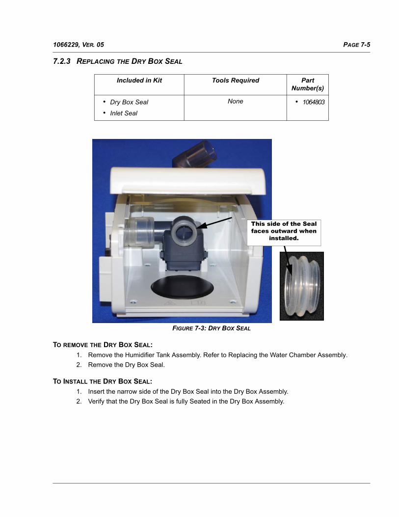
PAGE 7-51066229, VER. 05
7.2.3 REPLACING THE DRY BOX SEAL
FIGURE 7-3: DRY BOX SEAL
TO REMOVE THE DRY BOX SEAL:
1. Remove the Humidifier Tank Assembly. Refer to Replacing the Water Chamber Assembly.
2. Remove the Dry Box Seal.
TO INSTALL THE DRY BOX SEAL:
1. Insert the narrow side of the Dry Box Seal into the Dry Box Assembly.
2. Verify that the Dry Box Seal is fully Seated in the Dry Box Assembly.
Included in Kit Tools Required Part Number(s)
• Dry Box Seal
• Inlet Seal
None • 1064803
This side of the Seal faces outward when
installed.

PAGE 7-6 1066229, VER. 05
7.2.4 REPLACING THE DRY BOX ASSEMBLY/HUMIDIFIER INLET SEAL
FIGURE 7-4: BLOWER CAP
TO REMOVE THE DRY BOX ASSEMBLY/HUMIDIFIER INLET SEAL:1. Remove the Water Chamber Assembly. Refer to Section 7.2.1.
2. Insert a flat blade screwdriver into the hole located on the back of the Humidifier and lightly press inward to release the Dry Box Assembly. Refer to Figure 7-5.
3. Remove the Dry Box Assembly with Inlet Seal.
Included in Kit Tools Required Part Number(s)
• Dry Box Assembly
• Inlet Seal
• Dry Box Seal
Flathead Screwdriver • 1064804
CAUTION
Do not press firmly on the screwdriver as damage tothe Humidifier may occur.
Dry Box Assembly
Inlet Seal

PAGE 7-71066229, VER. 05
4. Remove the Inlet Seal from the Dry Box Assembly.
FIGURE 7-5: DRY BOX SEAL REMOVAL
TO INSTALL THE DRY BOX ASSEMBLY/HUMIDIFIER INLET SEAL:
1. Install The Inlet Seal onto the Dry Box Assembly if necessary.
2. Slide the Dry Box Assembly with Inlet Seal into its mounting location in the Humidifier Bottom Housing. Verify that the Dry Box Assembly with Inlet Seal are secured and do not fall out of the Housing.
Do not press firmly on the screwdriver handle. Very light
pressure is needed to release the Dry Box Assembly.
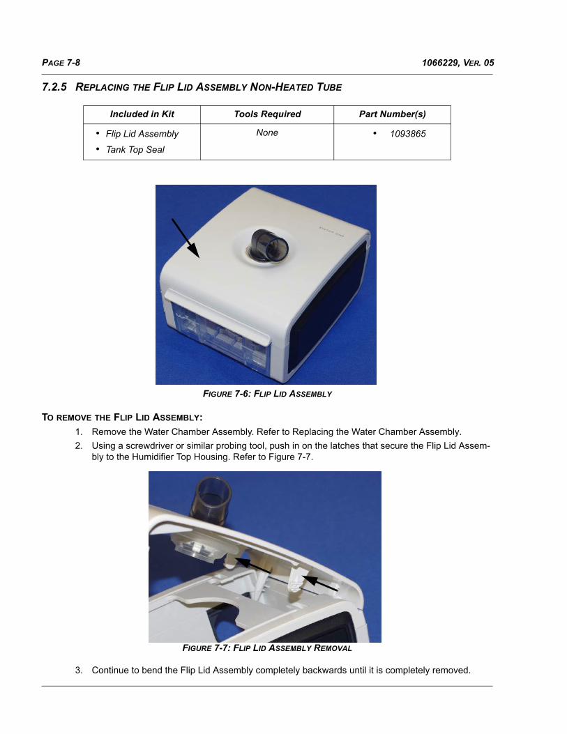
PAGE 7-8 1066229, VER. 05
7.2.5 REPLACING THE FLIP LID ASSEMBLY NON-HEATED TUBE
FIGURE 7-6: FLIP LID ASSEMBLY
TO REMOVE THE FLIP LID ASSEMBLY:
1. Remove the Water Chamber Assembly. Refer to Replacing the Water Chamber Assembly.
2. Using a screwdriver or similar probing tool, push in on the latches that secure the Flip Lid Assem-bly to the Humidifier Top Housing. Refer to Figure 7-7.
FIGURE 7-7: FLIP LID ASSEMBLY REMOVAL
3. Continue to bend the Flip Lid Assembly completely backwards until it is completely removed.
Included in Kit Tools Required Part Number(s)
• Flip Lid Assembly
• Tank Top Seal
None • 1093865

PAGE 7-91066229, VER. 05
TO INSTALL THE FLIP LID ASSEMBLY:
1. Install the Flip Lid Assembly Heated Tube guides into the base.
2. Continue to hinge forward until the latches are secured.
7.2.6 REPLACING THE FLIP LID ASSEMBLY HEATED TUBE
TO REMOVE THE FLIP LID ASSEMBLY HEATED TUBE:
1. Remove the Water Chamber Assembly. Refer to Replacing the Water Chamber Assembly.
2. Using a screwdriver or similar probing tool, push in on the latches that secure the Flip Lid Assem-bly to the Humidifier Top Housing. Refer to Figure 7-7.
3. Continue to bend the Flip Lid Assembly completely backwards until it is completely removed.
4. Remove the wire harness from the base. Refer to Figure 7-8.
FIGURE 7-8 FLIP LID ASSEMBLY WIRE HARNESS REMOVAL
TO INSTALL THE FLIP LID ASSEMBLY HEATED TUBE:
1. Connect the Flip Lid Assembly Heated Tube wire harness to the base. Refer to Figure 7-8.
2. Install the Flip Lid Assembly Heated Tube guides into the base.
3. Continue to hinge forward until the latches are secured.
Included in Kit Tools Required Part Number(s)
• Flip Lid Assembly
• Tank Top Seal
None • 1114892

PAGE 7-10 1066229, VER. 05
7.2.7 REPLACING THE HUMIDIFIER TOP HOUSING
FIGURE 7-9: HUMIDIFIER TOP HOUSING
TO REMOVE THE HUMIDIFIER TOP HOUSING:
1. Remove the Water Chamber Assembly. Refer to Section 7.2.1.
2. Using a T8 Torx screwdriver, remove the four #4 x 1/2” screws that secure the Top Housing to the Humidifier Bottom Housing.
3. Lift the Top Housing off of the Bottom Housing.
TO INSTALL THE HUMIDIFIER TOP HOUSING:
1. Place the Top Housing onto the Bottom Housing.
2. Secure the Top Housing to the Bottom Housing using the four #4 x 1/2” screws.
Included in Kit Tools Required Part Number(s)
• Top Housing
• #4 X 1/2” screw (x4)
T8 Torx Screwdriver • 1093966

PAGE 7-111066229, VER. 05
7.2.8 REPLACING THE HUMIDIFIER OUTSIDE COVER
FIGURE 7-10: OUTSIDE COVER
TO REMOVE THE HUMIDIFIER TOP HOUSING:1. Remove the Water Chamber Assembly. Refer to Section 7.2.1.
2. Remove the Flip Lid Assembly. Refer to Replacing the Flip Lid Assembly Non-Heated Tube.
3. Remove the Top Housing. Refer to Replacing the Humidifier Top Housing.
4. Slide the Outside Cover out of the Bottom Housing.
TO INSTALL THE OUTSIDE COVER:
• Slide the Outside Cover into the Bottom Housing.
Included in Kit Tools Required Part Number(s)
• Outside Cover T8 Torx Screwdriver • 1064808

PAGE 7-12 1066229, VER. 05
7.2.9 REPLACING THE HUMIDIFIER BOTTOM HOUSING
FIGURE 7-11: HUMIDIFIER BOTTOM HOUSING (HEATER PLATE SHOWN HERE, BUT IS NOT INCLUDED IN KIT)
TO REMOVE THE HUMIDIFIER BOTTOM HOUSING:1. Remove the Water Chamber Assembly. Refer to Section 7.2.1.
2. Remove the Flip Lid Assembly. Refer to Replacing the Flip Lid Assembly Non-Heated Tube.
3. Remove the Dry Box Assembly with Inlet Seal. Refer to Replacing the Dry Box Assembly/Humidi-fier Inlet Seal.
4. Remove the Top Housing. Refer to Replacing the Humidifier Top Housing.
5. Remove the Outside Cover. Refer to Replacing the Humidifier Outside Cover.
6. Remove the Left Side Panel.
7. Using a T15 Torx screwdriver, remove the four #6 x 1/4” screws that secure the Bottom Housing to the Lower Base Assembly.
TO INSTALL THE HUMIDIFIER BOTTOM HOUSING:
1. Place the Bottom Housing onto the Lower Base Assembly.
Included in Kit Tools Required Part Number(s)
• Bottom Housing • T8 Torx Screwdriver
• T15 Torx Screwdriver
• 1064808
CAUTION
Route the Heater Plate wiring harness so as not to causedamage during installation of the Humidifier Bottom Housing.

PAGE 7-131066229, VER. 05
2. Verify that the Heater Plate Wiring Harness is properly routed in the Lower Base Assembly and not at risk of being pinched or damaged.
3. Using the four #6 x 1/4” screws, secure the Bottom Housing to the Lower Base Assembly. Torque screws to 5 in.-lbs.

PAGE 7-14 1066229, VER. 05
7.2.10 REPLACING THE HEATER PLATE ASSEMBLY
FIGURE 7-12: HEATER PLATE ASSEMBLY
To remove the Heater Plate Assembly:
1. Remove the Water Chamber Assembly. Refer to Section 7.2.1.
2. Remove the Flip Lid Assembly. Refer to Replacing the Flip Lid Assembly Non-Heated Tube.
3. Remove the Dry Box Assembly with Inlet Seal. Refer to Replacing the Dry Box Assembly/Humidi-fier Inlet Seal.
4. Remove the Top Housing. Refer to Replacing the Humidifier Top Housing.
5. Remove the Outside Cover. Refer to Replacing the Humidifier Outside Cover.
6. Remove the Humidifier Bottom Housing. Refer to Replacing the Humidifier Bottom Housing.
7. Remove the Heater Plate Assembly.
To install the Heater Plate Assembly:
1. Place the Heater Plate Assembly into the Humidifier Lower Base as shown in Figure 7-13. Be sure that the Heater Plate Spring is properly seated under the Heater Plate.
Included in Kit Tools Required Part Number(s)
• Bottom Housing (with Left Side Panel)
• #6 X 1/4” screw (x4)
• T8 Torx Screwdriver
• T15 Torx Screwdriver
• 1093867

PAGE 7-151066229, VER. 05
FIGURE 7-13: HEATER PLATE INSTALLATION
2. Secure the Bottom Housing to the Lower Base using the four #6 x 1/4” screws and assemble the remainder of the device as necessary.
The Heater Plate Assembly is secured by three tabs.

PAGE 7-16 1066229, VER. 05
7.2.11 REPLACING THE SLIDER DOCKING LATCH
FIGURE 7-14: HEATER PLATE ASSEMBLY
To remove the Slider Docking Latch:
1. Remove the Water Chamber Assembly. Refer to Section 7.2.1.
2. Remove the Flip Lid Assembly. Refer to Replacing the Flip Lid Assembly Non-Heated Tube.
3. Remove the Dry Box Assembly with Inlet Seal. Refer to Replacing the Dry Box Assembly/Humidi-fier Inlet Seal.
4. Remove the Top Housing. Refer to Replacing the Humidifier Top Housing.
5. Remove the Outside Cover. Refer to Replacing the Humidifier Outside Cover.
6. Remove the Humidifier Bottom Housing. Refer to Replacing the Humidifier Bottom Housing.
7. Remove the Heater Plate Assembly.
To install the Slider Docking Latch:
1. Slide the Slider Docking Latch into slot in through the top of the Humidifier Base Housing as shown in Figure 7-15.
Included in Kit Tools Required Part Number(s)
• Bottom Housing (with Left Side Panel)
• #6 X 1/4” screw (x4)
• T8 Torx Screwdriver
• T15 Torx Screwdriver
• 1093866
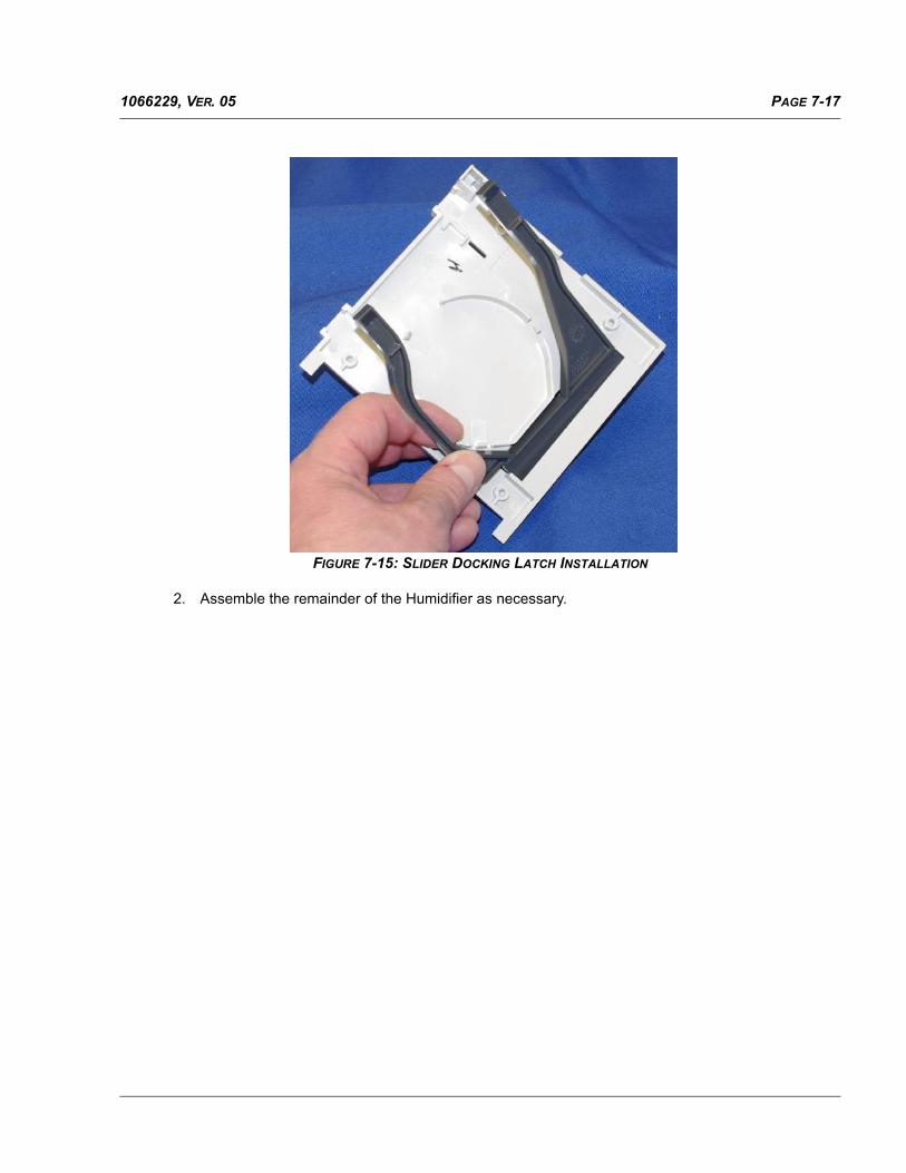
PAGE 7-171066229, VER. 05
FIGURE 7-15: SLIDER DOCKING LATCH INSTALLATION
2. Assemble the remainder of the Humidifier as necessary.

PAGE 7-18 1066229, VER. 05
This page intentionally blank.

PAGE 8-11066229, VER. 05
CHAPTER 8: TESTING & CALIBRATION
8.0 SECTION OVERVIEW
This section provides the necessary performance testing and final testing procedure for the BiPAP A30 &BiPAP A40 devices. Final Testing is necessary when a repair has been made to the device. However, this testmay be conducted to determine that the device is functioning properly between patient usage or wheneverdesired.
8.1 PREVENTIVE MAINTENANCE
There is no Preventive Maintenance required for this device.
8.2 CLEANING
1. Unplug the device, and wipe the outside of it with a cloth slightly dampened with water and a mild detergent. Let the device dry completely before plugging in the power cord.
2. Inspect the device and all circuit parts for damage after cleaning. Replace any damaged parts.
3. Allow the device to dry completely before plugging in the power cord.
8.2.1 CLEANING AND DISINFECTION FOR MULTIPLE USERS
When using the device on multiple users, complete the following steps to clean and disinfect the device beforeeach new user.
1. Unplug the device before disinfecting.
2. Disinfect the outside of the device only. Use a cloth with one of the following cleaning agents to clean the exterior of the device:
• Hydrogen Peroxide, 3%
• 91% Isopropyl Alcohol
• Vinegar, 5% acidity
WARNING
To avoid electrical shock, always unplug the powercord from the wall outlet before cleaning the device.
CAUTION
Do not immerse the device in liquid or allow any liquidto enter the enclosure, inlet filter, or any opening.
WARNING
If you are using the device on multiple users, discard the bacteria filter each time the device isused on a different person.

PAGE 8-2 1066229, VER. 05
• Water
• Chlorine bleach, household, 5.25% sodium hypochlorite, 1 to 5 part reduction with water.
3. Allow the device to dry completely before plugging in the power cord.
8.2.2 CLEANING AND REPLACING THE FILTERS
Under normal usage, you should clean the gray foam filter at least once every two weeks and replace it with anew one every six months. The white ultra-fine filter is disposable and should be replaced after 30 nights of useor sooner if it appears dirty. DO NOT clean the ultra-fine filter.
1. Disconnect the device from the power source.
2. Remove the filter(s) from the enclosure by gently squeezing the filter in the center and pulling it away from the device.
3. Examine the filter(s) for cleanliness and integrity.
4. Wash the gray foam filter in warm water with a mild detergent. Rinse thoroughly to remove all detergent residue. Allow the filter to air dry completely before reinstalling it. If the foam filter is torn, replace it. Only Respironics-supplied filters should be used as replacement filters.
5. If the white ultra-fine filter is dirty or torn, replace it.
6. Reinstall the filters, inserting the white ultra-fine filter first if applicable.
8.2.3 CLEANING THE REUSABLE TUBING
Disconnect the flexible tubing from the device. Gently wash the tubing in a solution of warm water and a milddetergent. Rinse thoroughly and allow the tubing to air dry. The patient tubing should be cleaned daily.
CAUTION
Operating the device with a dirty filter may keep the systemfrom working properly and may damage the device.
CAUTION
Dirty inlet filters may cause high operating temperatures that may affect deviceperformance. Regularly examine the inlet filters as needed for integrity and cleanliness.
CAUTION
Never install a wet filter into the device. You mustensure sufficient drying time for the cleaned filter.

PAGE 8-31066229, VER. 05
8.2.4 CLEANING THE HUMIDIFIER TANK
1. Turn the therapy device off and allow approximately 15 minutes for the heater plate and water to cool.
2. Disconnect the Patient Tubing from the device.
3. Remove the Humidifier Tank Assembly. Empty any remaining water.
4. Separate the Humidifier Tank Lid from the Humidifier Tank Base. Refer to Figure 8-1.
FIGURE 8-1: SEPARATING THE HUMIDIFIER TANK LID FROM THE TANK BASE
5. Wash the Humidifier Tank Lid and Tank Base by hand in a solution of warm water and mild dish-washing soap.
6. Inspect all parts for damage prior to reassembly.
7. Reassemble the Humidifier Tank.
8. Fill the Humidifier Tank to the fill line. Inspect the Humidifier Tank for any leaks or damage. Replace the entire Humidifier Tank Assembly if damaged.
NOTE
Hand washing The Humidifier Tank can be performed daily.
WARNING
• Empty and clean the Humidifier Tank daily to prevent mold and bacteria growth.
• Allow the water in the Humidifier Tank to cool to room temperature beforeremoving the chamber from the humidifier.
Middle Seal
Hinge s
Tab
Water ChamberBase
Water ChamberLid
Hinge s

PAGE 8-4 1066229, VER. 05
8.3 SYSTEM CHECKOUT PROCEDURE
This test procedure may be performed prior to connecting the device to a patient or in between patient usage.The tests should be performed as described in order to verify proper operation of the device.
8.3.1 CLEARING PATIENT DATA
To eliminate patient confidentiality concerns and to remove previous patient therapy settings, the Clear PatientData function removes all patient-stored data.
Clear Patient Data
This option appears on the Setup screen when the airflow is off and the device is in Standby.
It allows you to clear all patient data and visual alarms stored in the device memory and the device SD Card, ifinserted. It also clears the Modem SD Card data.
Clear Alarm Log
This option appears on the alarm log screen, when the airflow is off and the device is in Standby. It allows youto clear all displayed alarms and the device SD Card, if inserted. It also clears the Modem SD Card data. Pressthe button associated with the Clear function, and confirm the action by selecting “Yes.”

PAGE 8-51066229, VER. 05
8.3.2 GATHER DEVICE INFORMATION
1. If applicable, note or copy the patient’s therapy settings before testing begins.
2. If applicable, connect the device to a humidifier. Ensure that a clean or new gray foam filter is installed in the device.
3. Record the serial number and model number on the data sheet.
4. Record the model name on the data sheet.
5. Connect AC power.
6. Power ON the device and record the firmware version on the data sheet.
7. Record the blower hours of the device on the data sheet.
NOTE
Clearing the alarm logs will not clear the device internal event log.
NOTE
When testing is complete and before patient use, an authorized individual should adjust the device tothe patient’s therapy settings.
PAGE 8-6 1066229, VER. 05
8.3.3 SYSTEM VERIFICATION EQUIPMENT REQUIRED
Use the following instructions to ensure that the device is functioning properly. The following equipment isrequired to verify the pressure:
• Philips Respironics recommended:
• Philips Respironics Whisper Swivel II (P/N 332113)
• Philips Respironics O2 Enrichment Final Assembly (P/N 312710)
• 0.25 inch orifice (P/N 332353)
• End cap, stopper, or equivalent (source locally)
• Philips Respironics flexible tubing (P/N 622038)
• Pressure tubing as needed
• Foam filter (P/N 1035443 – single pack)
• Philips Respironics Digital Manometer (P/N 302227) or equivalent
• Minimum Specifications
• 0 - 30 cm H2O (or higher)
• ±0.3 cm H2O accuracy (or better)
• ±0.1 cm H2O resolution (or better)
8.3.4 HEATED HUMIDIFIER PERFORMANCE CONFIRMATION
Humidifier preheat mode can be used to determine if the System One Heated Humidifier is working properly.The following steps should be followed to confirm the performance of the System One Heated Humidifier.
WARNING
If the device fails to perform within the stated specifications, have the system serviced by anauthorized Philips Respironics service facility.
NOTE
The device automatically compensates for pressure drops associated with a 6-foot (1.83 m) smoothbore tube. Additional pressure drops will occur when restrictive elements such as a bacteria filter orPass-over humidifier are added to the patient circuit. Always use a manometer to verify patient maskpressure.
WARNING
It is important to follow the exact steps below when performing this test in order to avoid injury. Readall steps first, before performing this test.

PAGE 8-71066229, VER. 05
1. While the ventilator and humidifier are not running, place your hand above the heater plate (with-out touching it) to assess the temperature of the heater plate when the humidifier is off for later comparison.
2. Disconnect the patient tubing (if attached) and remove the water chamber.
3. Verify that the humidification is enabled and set to 1.
4. In order to activate the preheat mode, the blower must be “off” and a humidifier must be attached. From the device’s Standby screen, press the Select button under the Preheat setting. The device will now be in preheat mode and the humidifier icon will illuminate during this time with the setting number 1.
5. Allow the device to run in preheat mode for 30 seconds.
6. Place your hand above the heater plate (without touching it) to confirm an increase in heater plate temperature.
7. Press the “Therapy” button to enter therapy and end preheat mode.
8. Press the power button and select Standby to end therapy.
9. Record the results on the data sheet.
WARNING
Do not place your hand directly on the heater plate at any time as it could result in an injury.
WARNING
Do not place your hand directly on the heater plate at any time as it could result in an injury.

PAGE 8-8 1066229, VER. 05
8.3.5 SYSTEM VERIFICATION TEST
1. Connect the patient tubing to the Base Unit /Humidifier outlet port. Refer to Figure 8-2.
FIGURE 8-2
2. Connect the Whisper Swivel II to the end of the patient tubing. Refer to Figure 8-3.
3. Place the O2 Enrichment Attachment on the end of the Whisper Swivel II. Refer to Figure 8-3.
4. Place the end cap on the end of the O2 Enrichment attachment. Refer to Figure 8-3.
FIGURE 8-3
5. Connect a Digital Manometer to the pressure pick-off on the O2 Enrichment attachment.
6. Enter the device’s Settings and Alarms section. (Refer to user manual Chapter 5, “Viewing and Changing Settings” (Setup), if necessary.)
7. Set the device to CPAP Mode and the pressure value to 4 cm H2O.
• For BIPAP SOH, set the device to:
• AVAPS-AE Mode
• AVAPS Rate to 0.5
• Tidal Volume to 200 ml

PAGE 8-91066229, VER. 05
• Maximum Pressure to 6 cm H2O
• Pressure Support Max to 2 cmH2O
• Pressure Support Min to 2 cm H2O
• EPAP Max Pressure to 4 cm H2O
• EPAP Min Pressure to 4 cm H2O
• BPM to 0
• Rise Time to 1
a. Exit the Setup menu, activate CPAP Mode (BiPAP SOH is AVAPS-AE), and then apply ther-apy.
b. Record the manometer reading on the test data sheet.
8. Enter the device’s Settings and Alarm Menu and set the CPAP pressure value to 20 cm H2O (BiPAP SOH, set the IPAP and EPAP AVAPS AE pressure to 20 cm H2O). Record the manometer value on the test data sheet.
9. Set the device to S mode and set the IPAP pressure to 10 cm H2O and EPAP pressure to 5 cm H2O. (BiPAP SOH, set to AVAPS AE mode. Set the IPAP pressure to 10 cm H2O and EPAP pres-sure to 5 cm H2O. Lower BPM (Breath Per Minute) to Very Low (4)(No Trigger))
a. Remove the end cap.
b. Fit 0.25 inch orifice, (P/N 332353)
c. Exit setup and activate S mode. (BiPAP SOH to AVAPS AE mode)
d. Enter therapy.
10. Occlude and then open the outlet repeatedly to verify that the device triggers and cycles between IPAP and EPAP modes on the display screen and the manometer. Record the results on the test data sheet.
11. Set the device to S/T mode (BiPAP SOH see bulleted items below) and set the IPAP pressure to 10 cm H2O, the EPAP pressure to 5 cm H2O, BPM to 10, Inspiration time (Ti) to 2.0, and Rise Time to 2. Exit setup, activate S/T mode, and apply therapy.
• BiPAP SOH set the device to:
• AVAPS AE mode
• AVAPS Rate to 0.5
• Tidal Volume to 300 ml
• Maximum Pressure to 10 cm H2O
• Pressure Support Max to 5 cm H2O
• Pressure Support Min to 5 cm H2O
• EPAP Max Pressure to 5 cm H2O
• EPAP Min Pressure to 5 cm H2O
• BPM to 40
• Rise Time to 1
12. Visually verify that the device switches between IPAP and EPAP modes on the display screen and record the results on the test data sheet.
Apnea Alarm Test
13. Set the Apnea Alarm setting = 10 seconds.
14. Exit to the Monitoring screen.

PAGE 8-10 1066229, VER. 05
15. Simulate breathing by alternately occluding and opening the outlet port; then occlude the outlet port.
16. Verify that the Apnea alarm occurs in approximately 10 seconds.
17. Press the “Reset” button to clear the alarm.
18. Set the Apnea Alarm setting to 0 (Off).
19. Record the Apnea alarm test result on the data sheet.
Circuit Disconnect Alarm Test
20. Set the Circuit Disconnect Alarm = 15 seconds.
21. Exit to the Monitoring screen.
22. Connect a standard circuit with Whisper Swivel II and an end cap.
23. Simulate breathing by alternately occluding and opening the outlet port.
24. Remove the end cap.
25. Verify that the Circuit Disconnect Alarm occurs in approximately 15 seconds.
26. Press the “Reset” button to clear the alarm.
27. Set the Circuit Disconnect Alarm to Off.
28. Record the Circuit Disconnect Alarm test result on the data sheet.
Low Minute Ventilation Alarm Test
29. Simulate 6 breaths by alternately occluding and opening the outlet port for 2 seconds each.
30. Set the Low Minute Ventilation Alarm setting = 10.0 LPM.
31. Simulate 1 or 2 breaths by occluding and opening the outlet port.
32. Verify that the Low Minute Ventilation alarm occurs.
33. Set the Low Minute Ventilation Alarm setting to 0.0 (Off).
34. Record the Low Minute Ventilation alarm test result on the data sheet.
Loss of Input Power Alarm Test on AC Power (Base and Humidifier ONLY)
35. While the device is still operating, disconnect the power cord from the device.
36. Verify that a Loss of Input Power alarm sounds.
37. Record the Loss of Input Power Alarm test result on the data sheet.
Loss of Input Power Alarm Test - BiPAP A40 (with Detachable Battery)
38. Secure the Detachable Battery Module to the device. Ensure an adequately charged battery is used.
39. Power on the device and select any therapy mode. Disconnect the power cord from the device.
40. The device will switch over to battery operation. The display shows “AC Power Disconnected” and a tone sounds. Select Reset. A black box will appear around the battery indicator to show the ven-tilator is running on battery power. Record the test results on the data sheet.
41. Power the device off. Testing is complete.

PAGE 8-111066229, VER. 05
BiPAP A Series System Checkout Data Sheet
Tested by: ___________________________________ Date: ____________________________
Signature: ___________________________________
SECTION 8.3.2 DEVICE INFORMATION
Notification # (if applicable)
Step 3 Model # / Serial #
Step 4 Model name
Step 6 Device firmware revision
Step 7 Blower hours
SECTION 8.3.4 HUMIDIFIER RESULT (CIRCLE)
Step 9 Humidification test: Heater plate operation Pass / Fail
SECTION 8.3.5SYSTEM
VERIFICATION RESULT TOLERANCE RESULT (CIRCLE)
Step 7b CPAP @ 4 cmH2OBiPAP SOH AVAPS AE @ 4 cmH2O
[ ] ± 1 cmH2O[ ] ± 1 cmH2O
Pass / Fail
Step 8 CPAP @ 20 cmH2OBIPAP SOH AVAPS AE @ 20 cmH2O
[ ] ± 2 cmH2O[ ] ± 2 cmH2O
Pass / Fail
Step 10 S Mode trigger performance Pass / Fail
Step 12 S/T Mode – machine delivered breath Pass / Fail
Step 19 Apnea Pass / Fail
Step 28 Circuit or disconnect Pass / Fail
Step 34 Low minute ventilation Pass / Fail
Step 37 Loss of input power on AC Power Pass / Fail
Step 40 Loss of Input power Alarm Test - BiPAP A40 Battery Test Pass / Fail
NOTE
If the device does not pass all tests, then perform all necessary repairs and re-test per the service manualrequirement.

PAGE 8-12 1066229, VER. 05
Calibration and testing requires the use of custom software. Before proceeding, log on to http://my.respironics.com.
FIGURE 8-1: SOFTWARE LOCATION ON MY.RESPIRONICS.COM
8.4 REQUIRED EQUIPMENT
• Windows-compatible PC running Windows XP or 7 Operating System with:
• CD-ROM Drive,
• at least two (2) RS-232 serial/com ports, and
NOTE
UUT = Unit Under Test (i.e., the device you aretesting).

PAGE 8-131066229, VER. 05
• at least one (1) USB port.
• Digital Manometer (part #302227, or equivalent) with Pressure Tubing
• One (1) O2 Enrichment Attachment (part #312710)
• One (1) 1/4” Test Adapter (part #332353)
FIGURE 8-2: ENRICHMENT ATTACHMENT AND 1/4” ADAPTER
• End Cap (not available from Respironics), or similar part (i.e., CapLugs EC-14).
NOTE
• If you have less than two serial com ports, you must use a 4-port USB to RS-232 switch
• (PRI Part Number 1113089).
• Be sure to install the drivers for the 4-port USB to RS-232 switch.
Enrichment Attachment
1/4” Adapter
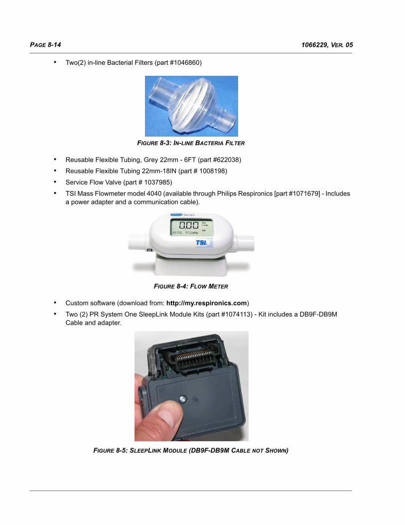
PAGE 8-14 1066229, VER. 05
• Two(2) in-line Bacterial Filters (part #1046860)
FIGURE 8-3: IN-LINE BACTERIA FILTER
• Reusable Flexible Tubing, Grey 22mm - 6FT (part #622038)
• Reusable Flexible Tubing 22mm-18IN (part # 1008198)
• Service Flow Valve (part # 1037985)
• TSI Mass Flowmeter model 4040 (available through Philips Respironics [part #1071679] - Includes a power adapter and a communication cable).
FIGURE 8-4: FLOW METER
• Custom software (download from: http://my.respironics.com)
• Two (2) PR System One SleepLink Module Kits (part #1074113) - Kit includes a DB9F-DB9M Cable and adapter.
FIGURE 8-5: SLEEPLINK MODULE (DB9F-DB9M CABLE NOT SHOWN)

PAGE 8-151066229, VER. 05
• *KeySpan Adapter (part #1022895)
FIGURE 8-6: KEYSPAN ADAPTER WITH CABLE
• Digital multi-meter
• Nurse Call cable (part #1080249)
FIGURE 8-7; DIGITAL MULTIMETER WITH NURSE CALL CABLE
• A30/A40- (Original or Silver Series) Humidifier compatible with the device being tested
• part #1076544 for Original Series
• part #1111552 for Silver Series
• Barcode Scanner with 2D scanning capabilities (optional)
• Printer
• One of the following therapy devices for negative flow
• BiPAP A30 (Original or Silver Series)
• BiPAP A40 (Original or Silver Series)

PAGE 8-16 1066229, VER. 05
• PR System One REMstar Plus C-Flex
• PR System One REMstar Pro C-Flex+
• PR System One REMstar Auto A-Flex
• PR System One BiPAP Pro Bi-Flex
• PR System One BiPAP Auto Bi-Flex
• BiPAP S/T (System One platform)
• BiPAP AVAPS (System One platform)
* If you have two serial/com ports on your PC, you can use the KeySpan USB to Serial adapter as the 3rdserial/com port. Otherwise, you will need a USB to RS-232 four (4) port switch (National Instruments USB-232/4 recommended [PRI P/N 1113089). If using a 4-port switch, the KeySpan adapter is not necessary.
8.5 DOWNLOADING AND INSTALLING THE TEST SOFTWARE
8.5.1 32 BIT VS. 64 BIT OS VERIFICATION
Do the following to determine your Operating System (32 Bit or 64 Bit). Refer to Figure 8-8.
1. Click on the Windows Start button.
2. Right-click on My Computer.
3. Click on Properties.
4. Go to the General tab.

PAGE 8-171066229, VER. 05
FIGURE 8-8: DETERMINING OPERATING SYSTEM BIT CONFIGURATION
If 64 bit is not specified your computer is 32 bit
(Windows XP)
1
2
3
4
If 64 bit is not specified your computer is 32 bit
(Windows 7)

PAGE 8-18 1066229, VER. 05
8.5.2 DOWNLOADING THE PHILIPS TS ENGINE AND FIELD SERVICE APPLICATION (FSA)
Philips TS Engine Installation
1. Log onto http://my.respironics.com and locate the software.
2. Based on the OS bit configuration determined in Section 8.2.1, click on the Download button adja-cent to the appropriate Philips TS Engine installer (32 bit or 64 bit) for your PC.
FIGURE 8-9: PHILIPS TS ENGINE DOWNLOAD
3. Choose Run or Save based on whether or not you are installing on one PC or multiple PCs.
4. Follow the prompts to complete the installation.
5. When Philips TS Engine installation is complete, you will be prompted to restart the PC. Restart the PC prior to beginning the FSA software installation.
FSA Software Installation (Field Service Application [FSA])
1. Log onto http://my.respironics.com and locate the software.
FIGURE 8-10: FSA DOWNLOAD
2. Based on the OS bit configuration determined in Section 8.2.1, click on the Download button adja-cent to the appropriate FSA installer (32 bit or 64 bit) for your PC.
3. Choose Run or Save based on whether or not you are installing on one PC or multiple PCs.
4. Follow the prompts to complete the installation.
5. If installed on a Windows 7 OS, proceed to section Section 8.5.3. If not using Windows 7 OS, pro-ceed to Section 8.6.
Version Number May Be Different than Shown
Version Number May Be Different than Shown

PAGE 8-191066229, VER. 05
8.5.3 COMPATIBILITY SETTINGS FOR WINDOWS 7 USERS
If you have installed the FSA software and Toolbox onto a PC that is running Windows 7 OS, you must run theapplications as an administrator. To set the applications with administrator privileges, perform the following.
1. Right-click on the application’s desktop icon.
2. Select Properties.
FIGURE 8-11: APPLICATION PROPERTIES
3. Click on the Compatibility tab. Refer to Figure 8-12.
4. Click on the Change Settings for all users button. A new window will appear. Refer to Figure 8-12.
5. Check the box next to Run this program as an administrator option. Refer to Figure 8-12.
6. Click on the Apply button. Refer to Figure 8-12.
7. Click on the OK button to close the window. Refer to Figure 8-12.
FIGURE 8-12: COMPATIBILITY TAB
3
4
5
7
6

PAGE 8-20 1066229, VER. 05
8.6 HARDWARE SETUP
Set up your equipment according the diagram below and proceed to the Qualification Procedure (Section 8.7).
FIGURE 8-13: HARDWARE SETUP
Throughout the test, you will be prompted to occlude, connect negative flow source, etc. at this side of the TSI
Mass Flowmeter 4040
6 Foot Smooth Bore Tube

PAGE 8-211066229, VER. 05
FIGURE 8-14: TESTING SETUP AND CONFIGURATIONS
8.6.1 COM PORT CONFIGURATION
COM port setup must be performed as follows (refer to Figure 8-15):
1. Connect the device being tested to the physical port 1 on your PC or switch.
2. Connect the TSI Mass Flowmeter 4040 to the physical port 2 on your PC or switch.
3. Connect the negative flow device to the physical port 3 on your PC (USB adapter) or switch.
4. Using Windows device manager, configure the ports as follows Refer to Figure 8-15:
• Configure Port 1 to COM17 (device being tested)
• Configure Port 2 to COM18 (TSI Mass Flowmeter 4040)
• Configure Port 3 to COM19 (negative flow device)
Connect to Physical Port 1 (Virtual Port 17) Connect to Physical
Port 2 (Virtual Port 18)
Connect to Physical Port 3 (Virtual Port 19)
6 FOOT SMOOTH BORE
TUBE

PAGE 8-22 1066229, VER. 05
FIGURE 8-15: PORT CONFIGURATION
From the Start menu, Right click on “My Computer”, then click on “Manage”
Click on “Device Manager”
Select the Port, then Right click to access
“Properties”
Click on the “Port Settings” tab, then click on the “Advanced” Button
Select the correct COM number (17, 18, and 19)
2
3
1
4
5

PAGE 8-231066229, VER. 05
8.7 QUALIFICATION PROCEDURE
This qualification procedure must be completed prior to testing repaired devices. The FSA test equipment mustpass the qualification procedure on a “known good” unit before being used for testing. The qualificationprocedure will determine if the test station hardware has been setup correctly and is functioning properly. Thequalification procedure must be performed upon initial setup of the test station or whenever any test equipmenthas been replaced (e.g., hardware components, PC, etc.) To conduct the qualification procedure, perform thefollowing:
1. Verify that all of the necessary equipment specified in Equipment list has been obtained (refer to Section 8.4).
2. Connect all the equipment as per the post station block diagram Refer to Figure 8-13.
3. On the test PC, assign the correct COM port numbers for each port. Refer to Section 8.6
a. Device being tested-COM17
b. TSI Flow meter-COM18
c. Negative Flow Source-COM19
4. Click on the ANIV Post Test icon located on the PC’s desktop to launch the FSA software.
FIGURE 8-16: FSA DESKTOP ICON
5. Log in as a Technician.
FIGURE 8-17: LOGIN WINDOW
6. Run the following individual tests (refer to Section 8.9 for running individual tests).
• Verify UUT Neg. Flow
• Verify Pressure
7. Print the report and verify that the overall test status is a PASS.
Only the successful completion of ALL of the Qualification Procedure’s steps will result in an overall PASSstatus for the Qualification Procedure. After the qualification procedure test passes, you may begin testingrepaired devices.

PAGE 8-24 1066229, VER. 05
8.8 TESTING A DEVICE
You must run-in the device after performing repairs and prior to testing. The first three steps below explain howto run-in the device:
1. Connect a 1/4” test adapter to the Outlet Coupler of the device.
2. Enter the Provider Setup Mode and set the device to operate in S/T Mode.
3. Disable alarms.
4. Set the device’s IPAP to 12 cm H2O and the EPAP to 4 cm H2O.
5. Turn on the device’s Blower and allow it to run-in for a minimum of one (1) hour.
6. After the device has been run-in, click on the ANIV Post Test icon located on the PC’s desktop to launch the FSA.
FIGURE 8-18: FSA DESKTOP ICON
7. Select Operator from the User Name drop-down menu, then click the OK button.
FIGURE 8-19: LOGIN WINDOW
8. Click on the Test UUTs button located at the bottom of the screen.
FIGURE 8-20: TEST UUTS BUTTON

PAGE 8-251066229, VER. 05
9. When prompted, enter or scan the device’s model number and serial number into the appropriate fields. The serial number and model number label appears on the bottom of the device.
FIGURE 8-21: ENTER SERIAL NUMBER AND MODEL NUMBER
10. The FSA will guide you through the entire testing process. Follow the on-screen prompts to com-plete the testing.
11. When prompted to adjust pressure settings to specific values, use the buttons on the left of the dis-play window to increase or decrease the pressure by 1.0 cm H2O (rough tune) and the buttons on
NOTE
Scanning the 2D bar code will automatically populate theserial and model number fields. Refer to Figure 8-21
Serial Number-Enter all characters with
no spaces.
Scan this 2D bar code if using a
scanner.
Model Number

PAGE 8-26 1066229, VER. 05
the right to increase or decrease the pressure by 0.1 cm H2O (fine tune). Refer to the following illustration for additional information.
FIGURE 8-22: SETTING ADJUSTMENT WINDOW
12. Once you have completed the test, a status banner will display either Pass, Fail, or Error.
13. If the device fails, check all connections, equipment, and configurations and re-test the device.
14. If the device fails again, perform necessary repairs and retest.
15. Once testing is complete, a report will be printed. You can maintain the printout for your records. If you are running individual tests in Troubleshooting mode, you will be asked if you would like a printout of the test results.
8.9 RUNNING INDIVIDUAL TESTS
To run individual test, perform the following:
1. Click on the ANIV Post Test icon located on the PC’s desktop to launch the FSA software.
FIGURE 8-23: FSA DESKTOP ICON
Click on these buttons to rough tune.
Click on these buttons to fine tune.

PAGE 8-271066229, VER. 05
2. Log in as a Technician. No password is required
FIGURE 8-24: LOGIN WINDOW
3. When the FSA main window appears, select the test(s) you desire to run by holding down the CTRL key on the test PC keyboard and clicking them as shown.
4. Right-click on the highlighted item. If you have selected more than one, right-click on any of them.
5. Point your mouse to Run Selected Steps Using, then click on Single Pass. Refer to Figure 8-25.
FIGURE 8-25: SELECTING INDIVIDUAL TESTS
NOTE
Individual tests can only be performed when you are logged in as a Technician.
NOTE
Individual tests can not be run by clicking on the Single Pass buttonlocated at the bottom of the FSA application window. Clicking on thisbutton will invoke the entire testing process one time.
3
5
4

PAGE 8-28 1066229, VER. 05
8.10 USING THE TOOLBOX APPLICATION
The Toolbox application allows you to:
• Read Error Log,
• Read Serial Number and Model Number,
• Calibrate the Real-time Clock,
• Set Machine Hours, and
• Set session ID.
The following sections provide a description of the tools.
8.10.1 READ ERROR LOG
Refer to Chapter 5 for information on reading the device’s error log.
8.10.2 READ SERIAL NUMBER AND MODEL NUMBER
When you execute the Read Serial Number and Model Number tool, the device’s serial number and modelnumber will be displayed as shown in the following illustration.
FIGURE 8-26: READ SERIAL NUMBER MODEL NUMBER TOOL

PAGE 8-291066229, VER. 05
8.10.3 CALIBRATE THE REAL-TIME CLOCK
To verify the device’s current real-time clock is within acceptable limits, click on the VERIFY RT CLOCK button.If the real-time clock verification fails, click on the SET RT CLOCK button to reset the device’s Real-time Clock.
FIGURE 8-27: REAL-TIME CLOCK TOOL

PAGE 8-30 1066229, VER. 05
8.10.4 SET MACHINE HOURS
It is recommended that when a new PCA is installed in the device, the machine hours be set to the number ofhours stored in the device when it was received for service.
FIGURE 8-28: SET MACHINE HOURS
8.10.5 SET SESSION ID
It is recommended that when a new PCA is installed in the device, the Session ID be set. Using the SetSession ID helps to prevent overwriting existing patient data. When you execute the Set Session ID tool, youwill be prompted to enter the manufacturing date of the device. The manufacturing date is located on the SerialNumber label on the bottom of the device.
FIGURE 8-29: MANUFACTURING DATE ON THE BOTTOM OF THE DEVICE
Enter the number of hours the machine had
on it when it was received for service.
Mfg. Date

PAGE 9-11066229, VER. 05
CHAPTER 9: DEVICE SOFTWARE UPGRADING
9.0 SECTION OVERVIEW
This section provides instructions for upgrading the device’s Operating Software and Boot Monitor Software.
FIGURE 9-1: SOFTWARE LOCATION ON MY.RESPIRONICS.COM
9.1 REQUIRED EQUIPMENT
• Windows-compatible personal computer running Windows XP or 7 with:
• CD-ROM Drive,
• One (1) RS-232 serial/com ports, and
• at least one (1) USB port
NOTE
UUT = Unit Under Test (i.e., the device you aretesting).

PAGE 9-2 1066229, VER. 05
• SD Card drive or adapter that connects to a PC
• One (1) PR System One SleepLink Module Kits (part #1074113) - Kit includes a DB9F-DB9M Cable and adapter.
FIGURE 9-2: SLEEPLINK MODULE (DB9F-DB9M CABLE NOT SHOWN)
• KeySpan Adapter (part #1022895)
FIGURE 9-3: KEYSPAN ADAPTER WITH CABLE
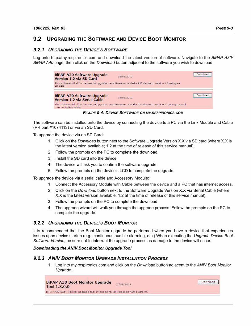
PAGE 9-31066229, VER. 05
9.2 UPGRADING THE SOFTWARE AND DEVICE BOOT MONITOR
9.2.1 UPGRADING THE DEVICE’S SOFTWARE
Log onto http://my.respironics.com and download the latest version of software. Navigate to the BiPAP A30/BiPAP A40 page, then click on the Download button adjacent to the software you wish to download.
FIGURE 9-4: DEVICE SOFTWARE ON MY.RESPIRONICS.COM
The software can be installed onto the device by connecting the device to a PC via the Link Module and Cable(PR part #1074113) or via an SD Card.
To upgrade the device via an SD Card:
1. Click on the Download button next to the Software Upgrade Version X.X via SD card (where X.X is the latest version available; 1.2 at the time of release of this service manual).
2. Follow the prompts on the PC to complete the download.
3. Install the SD card into the device.
4. The device will ask you to confirm the software upgrade.
5. Follow the prompts on the device’s LCD to complete the upgrade.
To upgrade the device via a serial cable and Accessory Module:
1. Connect the Accessory Module with Cable between the device and a PC that has internet access.
2. Click on the Download button next to the Software Upgrade Version X.X via Serial Cable (where X.X is the latest version available; 1.2 at the time of release of this service manual).
3. Follow the prompts on the PC to complete the download.
4. The upgrade wizard will walk you through the upgrade process. Follow the prompts on the PC to complete the upgrade.
9.2.2 UPGRADING THE DEVICE’S BOOT MONITOR
It is recommended that the Boot Monitor upgrade be performed when you have a device that experiencesissues upon device startup (e.g., continuous audible alarming, etc.) When executing the Upgrade Device BootSoftware Version, be sure not to interrupt the upgrade process as damage to the device will occur.
Downloading the ANIV Boot Monitor Upgrade Tool
9.2.3 ANIV BOOT MONITOR UPGRADE INSTALLATION PROCESS
1. Log into my.respironics.com and click on the Download button adjacent to the ANIV Boot Monitor Upgrade.

PAGE 9-4 1066229, VER. 05
FIGURE 9-5: BOOT MONITOR UPGRADE TOOL ON MY.RESPIRONICS.COM
2. Save the ANIV Boot Monitor Upgrade Tool installer to your PC (default location is recommended).
3. Locate the BiPAPA30_Boot_Monitor_Upgrade_Tool.exe on your computer and double click on it to begin the installation.
FIGURE 9-6: BOOT MONITOR UPGRADE TOOL IN EXPLORER
4. When you double-click on the BiPAPA30_Boot_Monitor_Upgrade_Tool.exe, a new window will open. Click on the Unzip button to unzip the files
5. The self extractor will begin to unzip the necessary files.
FIGURE 9-7: BOOT MONITOR UPGRADE TOOL SELF EXTRACTOR
6. Once you have extracted the files, click on the license agreements (there are two of them).

PAGE 9-51066229, VER. 05
7. Click on the Next button when the following window appears. The installation will then begin.
FIGURE 9-8: BOOT MONITOR UPGRADE TOOL INSTALLATION
8. Click on the Finish button when the installation is complete. Once you have installed the Boot Mon-itor Upgrade tool, you will be prompted to restart the PC. Restart the PC prior to using the Boot Monitor Upgrade tool.
9. Configure, if necessary, the PC’s COM port that will be used by the Boot Monitor Upgrade tool to COM1. Refer to Section 8.6.1 for instructions on configuring COM ports.
10. Connect the SleepLink Module with cable (PR part #1074113) to the back of the device
11. Click on the desktop icon to invoke the Boot Monitor Upgrade tool.
NOTE
If installed on a Windows 7 OS, go to section Section 8.5.3 prior tousing the Boot Monitor Upgrade Tool. If the application is notinstalled on a PC using Windows 7 OS, disregard this note.
CAUTIONS
• The Boot Monitor Upgrade Tool must be connected to a nativeCOM Port or the KeySpan adapter (PR #1022895). Do not use amultiple-port USB to RS-232 switch for this tool.
• The use of inappropriate hardware could result in the interruption ofthe upgrade process, which in turn will render the deviceinoperable.

PAGE 9-6 1066229, VER. 05
FIGURE 9-9: BOOT MONITOR DESKTOP ICON
12. If you wish to proceed with upgrading the device’s boot monitor, click on the UPGRADE BOOT MONITOR SOFTWARE button as shown in Figure 9-10.
FIGURE 9-10: BOOT MONITOR UPGRADE TOOL
CAUTION
Once you confirm the selection to upgrade, avoid interrupting the bootmonitor version upgrade process. If the upgrade process is interrupted,the device will become inoperable.
Please remember to avoid interrupting the
upgrade process.

PAGE 9-71066229, VER. 05
13. After you click on the UPGRADE BOOT MONITOR SOFTWARE button, you will be asked to con-firm, as shown in Figure 9-11. Click on the UPGRADE button to upgrade the device’s boot monitor software.
FIGURE 9-11: CONFIRM BOOT MONITOR UPGRADE
14. If the upgrade was successful, you will get a Success message with the new version of the boot monitor software. If the device already has the latest boot monitor version, you will get a message saying you already have the latest software. If the upgrade fails, you will receive an unsuccessful upgrade message, at which point you may re-try the upgrade, or exit the tool.

PAGE 9-8 1066229, VER. 05
This page intentionally blank.

PAGE 10-11066229, VER. 05
CHAPTER 10: SCHEMATICS
10.0PROPRIETARY STATEMENT
Schematics are supplied in direct support of the sale and purchase of this product.
The Schematics are proprietary and confidential. Do not copy the schematics or disclose them to third partiesbeyond the purpose for which they are intended.
The schematics are intended to satisfy administrative requirements only. They are not intended to be used forcomponent level testing and repair. Any changes of components could effect the reliability of the device,prohibit lot tracking of electronic components, and void warranties. Repairs and testing are supported only atthe complete board level.
The schematics are of the revision level in effect at the time this manual was last revised. New revisions may ormay not be distributed in the future.
NOTE
The following schematics begin with page 2 of 13.Page 1 is not published because it does not includeany service-related information. Page 1 is reservedfor internal engineering revision history and trackingnotes.

PAGE 10-2 1066229, VER. 05
NO
PLA
NE
SYST
EM G
RO
UN
D P
LAN
E
POW
ER S
UPP
LY G
RO
UN
D
BA
TT P
OW
ER
10
-17V
DC
AC
- D
C24
VD
C
Pb
Aci
d B
atte
ry O
VLO
V_P
b >
18.6
5VD
C +
/- 5%
Pb
Aci
d B
atte
ry D
isab
leM
icro
Pro
cess
or C
ontro
lP
b A
cid
Bat
tery
Pow
er C
ontro
l
Bat
tery
Pow
er E
nabl
eV
_AC
< 9
.75V
DC
+/-
5%A
C-D
C P
ower
Idea
l Dio
de
Gai
n =
0.2V
/AR
ange
= 0
to 1
5.0A
(pea
k)A
ccur
acy
= 4.
5%
Fc =
320
KH
z
Pb
Aci
d B
atte
ry U
VLO
V_P
b <
9.5V
DC
+/-
5%
Wak
e U
p Li
Ion
Bat
tery
Li A
cid
Bat
tery
Pow
er C
ontro
l
Lith
ium
Ion
B
atte
ry12
- 16
.4V
DC
**
**
V_I
N
V_I
NV
_BU
S
V_P
b
PS
V_P
b
V_A
C
PS
V_A
C
V_L
i
V_A
C
V_I
N PS
PS
V_I
N
+9V
V_A
C
+3.3
VD
+3.3
VD
+3.3
VD
nBA
TT_E
NA
BLE
VS
EN
SE
_Pb
VS
EN
SE
_SP
AR
E
CU
RR
EN
T_S
YS
TEM
Pb_
DIS
AB
LE
nLI_
EN
AB
LE
nBA
TT_E
NA
BLE
Pb_
PR
ES
EN
T
VS
EN
SE
_AC
nLI_
EN
AB
LEnB
ATT
_EN
AB
LE
Li_SPARE
Li_SCL
Li_SDA
VS
EN
SE
_WA
TT
AC
_PR
ES
EN
T
Pb_
PR
ES
EN
T
Size
Scal
e
DWG
NOR
ev
Shee
tof
Part
No.
Title
:AL
L IN
FORM
ATIO
N CO
NTAI
NED
IN O
R DI
SCLO
SED
BYTH
ISDO
CUM
ENT
IS C
ONSI
DERE
D TO
BE
CONF
IDEN
TIAL
AND
PROP
RIET
ARY
BY R
ESPI
RONI
CS. A
LL D
ESIG
N,M
ANUF
ACTU
RING
, USE
AND
REP
RODU
CTIO
N RI
GHTS
RELA
TED
TO T
HIS
INFO
RMAT
ION,
AND
ALL
SAL
ESRI
GHTS
ASSO
CIAT
ED T
HERE
WIT
H, A
RE E
XPRE
SSLY
RES
ERVE
DBY AN
D TO
RES
PIRO
NICS
. USE
, REP
RODU
CTIO
N OR
DIST
IRBU
TION
OF
THIS
INFO
RMAT
ION,
OR
COM
MUN
ICAT
ION
OF T
HIS
INFO
RMAT
ION
TO O
THER
S, IS
PROH
IBIT
ED W
ITHO
UT T
HE P
RIOR
WRI
TTEN
CON
SENT
OF R
ESPI
RONI
CS.
CO
NFI
DEN
TIAL
AN
DPr
oduc
t Lin
e:
Proc
ess: SC
HEM
ATIC
DRN
BY:
CH
K BY
:
APPR
BY:
PRO
PRIE
TAR
Y IN
FOR
MAT
ION
Cus
tom
MAI
N B
OAR
DPO
WER
MG
MT
JK
EDM
S
AUTO
NIV
EDM
S
EDM
S
08/3
1/10
EDM
SN
A
S10
7538
4
1075
384
2138
R39
810
KR
398
10K
C28
747
00pF
C28
747
00pF
R43
510
KR
435
10K
R40
3
100K
R40
3
100K
R43
424
.9K
R43
424
.9K
C28
647
00pF
C28
647
00pF
C3
470p
FC
347
0pF
PP
14P
P14
CR47ESD5Z5.0T1G
CR47ESD5Z5.0T1G
C2
.033
uFC
2.0
33uF
R40
8
100K
R40
8
100K
C29
047
00pF
C29
047
00pF
CR49ESD5Z5.0T1G
CR49ESD5Z5.0T1G
PP
11P
P11
C1
1uF
C1
1uF
PP
16P
P16
R26
249K
R26
249K
R40
1
100K
R40
1
100K
+ C24
947
uF+ C
249
47uF
7 68
Q34
BS
C08
4P03
NS
3E 7 68
Q34
BS
C08
4P03
NS
3E 5
4
123
CR
56M
MS
Z524
8BT1
G18
V
CR
56M
MS
Z524
8BT1
G18
V
R27
24.9
KR
2724
.9K
TP1
TP1
PP
17P
P17
R41
824
.9K
R41
824
.9K
R40
9
499K
R40
9
499K
Q32
BC
847C
LT1G
Q32
BC
847C
LT1G
1
3 2
PP
9P
P9
CR
1
MB
RX
140
CR
1
MB
RX
140
PP
5P
P5
R41
524
9KR
415
249K
7 68
Q27
BS
C08
4P03
NS
3E
7 68
Q27
BS
C08
4P03
NS
3E
5
4
123
R4
24.9
K
R4
24.9
K
PP
1P
P1
CR
60C
R60
R39
7
100K
R39
7
100K
CR48ESD5Z5.0T1G
CR48ESD5Z5.0T1G
R432
4.99K
R432
4.99K
CR
59C
R59
C5
.033
uFC
5.0
33uF
C27
.1uFC27
.1uF
PP
28P
P28
PP
3P
P3
Q28
BC
847C
LT1GQ28
BC
847C
LT1G
1
3 2
Q46
BC
847C
LT1G
Q46
BC
847C
LT1G
1
3 2
R15 4.99
R15 4.99
CR
11
MB
RX
140
CR
11
MB
RX
140
C28
1000
pFC
2810
00pF
CR
55S
MA
J30C
A30
V
CR
55S
MA
J30C
A30
V
7 68
Q49
BS
C08
4P03
NS
3E
7 68
Q49
BS
C08
4P03
NS
3E
5
4
123
PP
8P
P8
C13
.1uFC13
.1uF
R42
0R
420
R41
924
.9K
R41
924
.9K
R39
610
KR
396
10K
C12
.1uFC12
.1uF
R30
100
R30
100
R44
1
100K
R44
1
100K
C28
947
00pF
C28
947
00pF
R43
815
KR
438
15K
R42
910
KR
429
10K
P1
CO
NN
-TH
M 5
PIN
RA
3.9
6mm
P1
CO
NN
-TH
M 5
PIN
RA
3.9
6mm
1 2 3 4 5
Q41
BC
847C
LT1G
Q41
BC
847C
LT1G
1
3 2
R2 24.9
K
R2 24.9
K
R40
724
9KR
407
249K
R44
0
100K
R44
0
100K
R29
100
R29
100
R43
7
100K
R43
7
100K
C24
1000
pFC
2410
00pF
CR
58S
MA
J30A
30V
CR
58S
MA
J30A
30V
PP
13P
P13
L1
170
OH
MS
@ 1
00M
Hz
10A
L1
170
OH
MS
@ 1
00M
Hz
10A12
43
R39
510
KR
395
10K
7 68
Q50
BS
C08
4P03
NS
3E
7 68
Q50
BS
C08
4P03
NS
3E
5
4
123
PP
27P
P27
PP
15P
P15
R3
249K
R3
249K
+ C25
047
uF+ C
250
47uF
OU
T
RS
-
RS
+V
CC
GN
D
GND
U2
MA
X40
73TA
UT-
T
OU
T
RS
-
RS
+V
CC
GN
D
GND
U2
MA
X40
73TA
UT-
T4
6
5
1
2
3
E1
1000 OHMS @ 100 MHZ
E1
1000 OHMS @ 100 MHZ
R41
4
100K
R41
4
100K
R431
4.99K
R431
4.99K
PP
07P
P07
R40
210
0KR
402
100K
Q31
BC
847C
LT1G
Q31
BC
847C
LT1G
1
3 2
CR
2
MB
RX
140
CR
2
MB
RX
140
TP3
TP3
CR
71S
MA
J30A
30V
CR
71S
MA
J30A
30V
R41
0
100K
R41
0
100K
PP
2P
P2
CR
53S
MA
J30A
30V
CR
53S
MA
J30A
30V
R13
24.9
KR
1324
.9K
Q26
BC
847C
LT1GQ26
BC
847C
LT1G
1
3 2
C4
470p
FC
447
0pF
Q48
BC
847C
LT1G
Q48
BC
847C
LT1G
1
3 2
R28
100
R28
100
R14
0.01
01WR14
0.01
01W
PP
4P
P4
CR
54M
MS
Z523
9BT1
G9.
1V
CR
54M
MS
Z523
9BT1
G9.
1V
R70
499K
R70
499K
R1
249K
R1
249K
R41
6
100K
R41
6
100K
PP
12P
P12
R39
910
KR
399
10K
CR
57M
MS
Z523
7BT1
G8.
2V
CR
57M
MS
Z523
7BT1
G8.
2V
7 68
Q33
BS
C08
4P03
NS
3E
7 68
Q33
BS
C08
4P03
NS
3E
5
4
123
PP
18P
P18
TP2
TP2
Q47
BC
847C
LT1G
Q47
BC
847C
LT1G
1
3 2
R16 4.99
R16 4.99
PP
10P
P10
R43
9
499K
R43
9
499K
C29
.1uFC29
.1uF
R40
010
0KR
400
100K
R41
7
499K
R41
7
499K
E3
1000 OHMS @ 100 MHZ
E3
1000 OHMS @ 100 MHZ
C28
847
00pF
C28
847
00pF
P2
CO
NN
-TH
M 6
PIN
RA
3.9
6mm
P2
CO
NN
-TH
M 6
PIN
RA
3.9
6mm
1 2 3 4 5 6
R40
6
100K
R40
6
100K
Q29
BC
847C
LT1GQ29
BC
847C
LT1G
1
3 2
R430
4.99K
R430
4.99K
R41
124
.9K
R41
124
.9K
R12
249K
R12
249K
C26
1000
pFC
2610
00pF
R43
3R
433
E2
1000 OHMS @ 100 MHZ
E2
1000 OHMS @ 100 MHZ
R41
3
100K
R41
3
100K
R40
44.
99K
R40
44.
99K
R40
510
KR
405
10K
R69
499K
R69
499K
Q30
BC
847C
LT1G
Q30
BC
847C
LT1G
1
3 2
C25
.1uFC25
.1uF

PAGE 10-31066229, VER. 05
VO
= 1
.25V
+/-
5%IO
= 1
00m
A(m
ax)
Hea
t Sin
k>
0.50
sq in
Hea
t Sin
k>
0.50
sq in
VO
= 5
V +
/- 5%
IO =
100
mA
(max
)
VO
= 3
.3V
+/-
5%IO
= 7
5mA
(max
)
Hea
t Sin
kN
ot r
equi
red
VO
= 3
.0V
+/-
.2%
IO =
15m
A(m
ax)
T
VO
= 9
V +
/- 5%
I_O
UT
= 50
0mA
F_S
W =
170
kHz
V_O
UT=
22V
+/-
2.5%
I_O
UT
= 3A
(max
)F_
SW
= 1
25kH
z
T
T
VO
= 3
.3V
+/-
5%I_
OU
T =
500m
AF_
SW
= 2
30kH
z
Sin
gle
pin
nets
Use
for
Hea
tSin
king
Sin
gle
pin
nets
Use
for
Hea
tSin
king
V_O
UT
= -9
.0 +
/- 5%
I_O
UT
= 10
mA
(max
)F_
SW
= 7
Khz
*
*
HE
AT
SIN
K1
HE
AT
SIN
K2
HE
AT
SIN
K3
HE
AT
SIN
K4
+1.2
5VD
+5V
+9V
+3.3
VA
+5V
+9V
+3V
_RE
F
+3.3
VD
V_B
US
V_B
OO
ST +9
V
+3.3
VD
V_B
US
-9V
+9V
V_B
OO
ST
V_B
OO
ST
nSLE
EP
WK
UP
_SD
WK
UP
_PW
R
AC
_PR
ES
EN
T
nSLE
EP
Size
Sca
le
DWG
NO
Rev
She
etof
Par
t No.
Title
:AL
L IN
FORM
ATIO
N CO
NTAI
NED
IN O
R DI
SCLO
SED
BYTH
ISDO
CUM
ENT
IS C
ONS
IDER
ED T
O B
E CO
NFID
ENTI
AL A
NDPR
OPR
IETA
RY B
Y RE
SPIR
ONI
CS. A
LL D
ESIG
N,M
ANUF
ACTU
RING
, USE
AND
REP
RODU
CTIO
N RI
GHT
SRE
LATE
D TO
THI
S IN
FORM
ATIO
N, A
ND A
LL S
ALES
RIG
HTS
ASSO
CIAT
ED T
HERE
WIT
H, A
RE E
XPRE
SSLY
RES
ERVE
DBY AN
D TO
RES
PIRO
NICS
. USE
, REP
RODU
CTIO
N O
RDI
STIR
BUTI
ON
OF
THIS
INFO
RMAT
ION,
OR
COM
MUN
ICAT
ION
OF
THIS
INFO
RMAT
ION
TO O
THER
S, IS
PRO
HIBI
TED
WIT
HOUT
THE
PRI
OR
WRI
TTEN
CO
NSEN
TO
F RE
SPIR
ONI
CS.
CO
NFI
DE
NTI
AL
AN
DP
rodu
ct L
ine:
Pro
cess
:
SC
HE
MA
TIC
DRN
BY:
CH
K B
Y:
AP
PR
BY
:
PR
OP
RIE
TAR
Y IN
FOR
MA
TIO
N
Cus
tom
MA
IN B
OA
RD
PO
WE
R S
UP
PLY
JK EDM
S
AU
TO N
IV
EDM
S
EDM
S
08/3
1/10
EDM
SN
A
S10
7538
4
1075
384
3138
L7
100u
H0.
72A
L7
100u
H0.
72A
C25
810
uFC
258
10uF
CR
815.
1VC
R81
5.1V
U26
TP
S40
200D
U26
TP
S40
200D
RC
1
CO
MP
3
VD
D8
ISN
S7
GD
RV
6
GN
D5
SS
2
FB
4
C26
04.
7uF
C26
04.
7uF
Q66
BSS123
Q66
BSS123
3
1
2
C25
410
0pF
C25
410
0pF
R35
88.
25K
R35
88.
25K
PP
23P
P23
PP
21P
P21
R33
724
9KR
337
249K
R10
249
R10
249
R26
74.
99R
267
4.99
CR
3
ST
PS
5L60
S
CR
3
ST
PS
5L60
S
Q43
FD
FS
2P10
6A
Q43
FD
FS
2P10
6A
A1
1C
18
A2
2C
27
D1
6
D2
5
S3
G4
R17
100K
R17
100K
C17
.1uFC17
.1uF
L6
100u
H0.
72A
L6
100u
H0.
72A
NC
U7
LM4040BIX3-3.0-T
NC
U7
LM4040BIX3-3.0-T
1 2
3
PP
67P
P67
PP
128
PP
128
C7
.1uFC7
.1uF
C22
1000
pFC
2210
00pF
C26
2.1
uFC
262
.1uF
C20
.1uFC20
.1uF
R19
866
R19
866
Q42
FD
FS
2P10
6A
Q42
FD
FS
2P10
6A
A1
1C
18
A2
2C
27
D1
6
D2
5
S3
G4
PP
124
PP
124
U1
LM34
78M
M
U1
LM34
78M
M
AG
ND
4
FB
3
ISE
N1
CO
MP
2F
A/S
D7
VIN
8
PG
ND
5
DR
6
PP
126
PP
126
R35
64.
99R
356
4.99
R50
01KR
500
1K
+C
268
100u
F+
C26
810
0uF
C25
710
00pF
C25
710
00pF
U3
TL3
17C
PW
U3
TL3
17C
PW
INP
UT
1O
UT
PU
T1
2
AD
JUS
T4
NC
15
OU
TP
UT
23
OU
TP
UT
36
OU
TP
UT
47
NC
28
PP
72P
P72
R36
349
.9K
R36
349
.9K
Q53
BS
S12
3Q
53B
SS
123
3
1
2
R36
4
4.99R36
4
4.99
Q54
BS
S12
3Q
54B
SS
123
3
1
2
Q51
BS
S12
3Q
51B
SS
123
3
1
2
C27
910
00pF
C27
910
00pF
Q52
BS
S12
3Q
52B
SS
123
3
1
2
C10
1000
pFC
1010
00pF
C26
4.1
uFC
264
.1uF
C18
64.
7uF
C18
64.
7uF
PP
24P
P24
R20
2.49
KR
202.
49K
R35
2
0.05
1/4WR35
2
0.05
1/4W
PP
25P
P25
R12
849
9R
128
499
R18
100
R18
100
678 Q
1B
SZ
105N
04N
SG
678 Q
1B
SZ
105N
04N
SG
5
4
123
C8
.1uF
C8
.1uF
R36
010
0KR
360
100K
Q2
BS
S12
3Q
2B
SS
123
3
1
2 U25
TP
S40
200D
U25
TP
S40
200D
RC
1
CO
MP
3
VD
D8
ISN
S7
GD
RV
6
GN
D5
SS
2
FB
4
R24
499K
R24
499K
R35
5
4.99R35
5
4.99
R6
6.04
KR
66.
04K
R36
1
0.05
1/4WR36
1
0.05
1/4W
C28
3
1000
pF
C28
3
1000
pF
C25
14.
7uF
C25
14.
7uF
PP
127
PP
127
R5
100K
R5
100K
R22 2KR22 2K
C25
31u
FC
253
1uF
PP
20P
P20
U30
TL7
660C
DR
U30
TL7
660C
DR
NC
1
CA
P+
2
CA
P-
4V
OU
T5
GN
D3
LV6
OS
C7
VC
C8
PP
70P
P70
C30
1uF
C30
1uF
C14
.1uFC14
.1uF
C23
.1uF
C23
.1uF
R35
356
.2K
R35
356
.2K
L2 10uH
9AL2 10uH
9A
R9
150K
R9
150K
C18
1uF
C18
1uF
PP
26P
P26
PP
19P
P19
R36
54.
99R
365
4.99
C27
310
uFC
273
10uF
R21
1.27
KR
211.
27K
C16
1000
pFC
1610
00pF
C25
61u
FC
256
1uF
C9
4.7u
FC
94.
7uF
U5
TL3
17C
PW
U5
TL3
17C
PW
INP
UT
1O
UT
PU
T1
2
AD
JUS
T4
NC
15
OU
TP
UT
23
OU
TP
UT
36
OU
TP
UT
47
NC
28
Q45
BS
S12
3Q45
BS
S12
3
3
1
2
C26
327
pFC
263
27pF
C21
1uF
C21
1uF
PP
69P
P69
R8 1KR8 1K
C26
1
1000
pF
C26
1
1000
pF
R35
420
KR
354
20K
R36
610
KR
366
10K
CR
4M
BR
X14
0C
R4
MB
RX
140
R36
72.
67K
R36
72.
67K
C11
.1uF
C11
.1uF
C28
5C
285
C18
210
00pF
C18
210
00pF
PP
125
PP
125
R7
0.00
51WR
70.
005
1W
C25
5.0
1uF
C25
5.0
1uF
R293
150
R293
150
C28
4
1000
pF
C28
4
1000
pF
C26
910
uFC
269
10uF
R33
9
ZE
RO
R33
9
ZE
RO
C26
710
uFC
267
10uF
C27
84.
7uF
C27
84.
7uF
+C
291
100u
F+
C29
110
0uF
+C
259
+C
259
R11
4.99
R11
4.99
C25
2
1000
pF
C25
2
1000
pF
PP
68P
P68
R33
649
9KR
336
499K
C15
1uF
C15
1uF
C18
510
0pF
C18
510
0pF
C26
51u
FC
265
1uF
R35
910
KR
359
10K
C26
610
00pF
C26
610
00pF
C19
1000
pFC
1910
00pF
R35
710
0KR
357
100K
R36
241
.2K
R36
241
.2K
R43
610
0KR
436
100K
U4
TL3
17C
PW
U4
TL3
17C
PW
INP
UT
1O
UT
PU
T1
2
AD
JUS
T4
NC
15
OU
TP
UT
23
OU
TP
UT
36
OU
TP
UT
47
NC
28
R23
249K
R23
249K
PP
22P
P22
+C
647
uF+
C6
47uF

PAGE 10-4 1066229, VER. 05
MOTOR
* * *
MOTOR TEMP
VO
S =
1.5
V +
/- 1
0%G
AIN
= 0
.150
V/A
RA
NG
E =
+/-
10A
(pk)
Fc
= 3
.18M
Hz
Fc
= 3
.18M
Hz
Fc
= 3
.18M
Hz
VO
S =
1.5
V +
/- 1
0%G
AIN
= 0
.150
V/A
RA
NG
E =
+/-
10A
(pk)
VO
S =
1.5
V +
/- 1
0%G
AIN
= 0
.150
V/A
RA
NG
E =
+/-
10A
(pk)
GA
IN =
0.1
67V
/AR
AN
GE
= 0
-18A
(pea
k)A
ccur
acy
= 5
%F
c =
160
kHz
Mot
or C
urre
nt T
hres
hold
= 1
0.0A
+/-
15%
(P
eak)
*
IB_
H
IA_
H
IC_
H
PH
AS
E_
A
PH
AS
E_
C
PH
AS
E_
B
IA_
L
IB_
L
IC_
L
PH
AS
E_
A
PH
AS
E_
B
PH
AS
E_
C
IA_
H
IB_
H
IC_
H
CU
RR
EN
T_
MO
TO
R
V_
MO
TO
R
+3
.3V
A
V_
MO
TO
R
+3
.3V
A
V_
MO
TO
R
+3
.3V
A
+3
.3V
A
+3
.3V
A
+9
V
+9
V
+9
V
V_
BO
OS
TV
_M
OT
OR
+3
.3V
D
+9
V PW
M_
AH
PW
M_A
L
CU
RR
EN
T_
A
PW
M_B
H
PW
M_B
L
CU
RR
EN
T_
B
PW
M_
CH
PW
M_
CL
CU
RR
EN
T_
C
MO
TO
R_
TE
MP
nM
OT
OR
_F
AU
LT
VS
EN
SE
_M
OT
OR
nM
OT
OR
_O
VE
R_
CU
RR
EN
T
Siz
e
Sca
le
DW
G N
OR
ev
She
etof
Par
t No.
Titl
e:A
LL IN
FOR
MA
TIO
N C
ON
TAIN
ED
IN O
R D
ISC
LOS
ED
BY
THIS
DO
CU
ME
NT
IS C
ON
SID
ER
ED
TO
BE
CO
NFI
DE
NTI
AL
AN
DP
RO
PR
IETA
RY
BY
RE
SP
IRO
NIC
S. A
LL D
ES
IGN
,M
AN
UFA
CTU
RIN
G, U
SE
AN
D R
EP
RO
DU
CTI
ON
RIG
HTS
RE
LATE
D T
O T
HIS
INFO
RM
ATI
ON
, AN
D A
LL S
ALE
SR
IGH
TSA
SS
OC
IATE
D T
HE
RE
WIT
H, A
RE
EX
PR
ES
SLY
RE
SE
RV
ED
BY
AN
D T
O R
ES
PIR
ON
ICS
. US
E, R
EP
RO
DU
CTI
ON
OR
DIS
TIR
BU
TIO
N O
F TH
IS IN
FOR
MA
TIO
N, O
RC
OM
MU
NIC
ATI
ON
OF
THIS
INFO
RM
ATI
ON
TO
OTH
ER
S, I
SP
RO
HIB
ITE
D W
ITH
OU
T TH
E P
RIO
R W
RIT
TEN
CO
NS
EN
TO
F R
ES
PIR
ON
ICS
.
CO
NF
IDE
NT
IAL
AN
DP
rodu
ct L
ine:
Pro
cess
:
SC
HE
MA
TIC
DR
N B
Y:
CH
K B
Y:
AP
PR
BY
:
PR
OP
RIE
TA
RY
INF
OR
MA
TIO
N
Cu
sto
m
MA
IN B
OA
RD
MO
TO
RJK
ED
MS
AU
TO
NIV
ED
MS
ED
MS
08/3
1/10
ED
MS
NA
S1
07
53
84
10
75
38
44
138
CR
8S
MC
J28
A2
8V
CR
8S
MC
J28
A2
8V
678
Q5
BS
Z1
05
N0
4N
SG
678
Q5
BS
Z1
05
N0
4N
SG
5
4
123
CR
61
MB
RX
14
0
CR
61
MB
RX
14
0
C1
44
.1u
FC
14
4.1
uF
PP
55
PP
55
678
Q8
BS
Z1
05
N0
4N
SG
678
Q8
BS
Z1
05
N0
4N
SG
5
4
123
R2
73
10
KR
27
31
0K
R5
7
1K
R5
7
1K
PP
50
PP
50
PP
37
PP
37
R6
0
82
5
R6
0
82
5
R5
0
82
5
R5
0
82
5
PP
42
PP
42
R3
43
10
KR
34
31
0K
R2
71
10
KR
27
11
0K
-+U
12
AT
SV
99
4IP
T
-+U
12
AT
SV
99
4IP
T3 2
1
CR
62
MB
RX
14
0
CR
62
MB
RX
14
0
C5
1C
51
678
Q4
BS
Z1
05
N0
4N
SG
678
Q4
BS
Z1
05
N0
4N
SG
5
4
123
PP
60
PP
60
R6
8
10
K
R6
8
10
K
PP
39
PP
39
R3
88
1K
R3
88
1K
C4
9.1
uF
C4
9.1
uF
CR
63
MB
RX
14
0
CR
63
MB
RX
14
0
C3
11
uF
C3
11
uF
E66
50
OH
MS
@ 1
00
MH
z
E66
50
OH
MS
@ 1
00
MH
z
R4
6
4.9
9
R4
6
4.9
9
PP
13
2P
P1
32
R3
90
1K
R3
90
1K
C4
2.0
1u
FC
42
.01
uF
PP
46
PP
46
R4
3
4.9
9
R4
3
4.9
9
678
Q6
BS
Z1
05
N0
4N
SG
678
Q6
BS
Z1
05
N0
4N
SG
5
4
123
R3
4
10
0
R3
4
10
0
R3
41
1K
R3
41
1K
PP
33
PP
33
CR
5E
SD
5Z
12
T1
GC
R5
ES
D5
Z1
2T
1G
C5
4
10
0p
F
C5
4
10
0p
F
PP
57
PP
57
R3
1
10
0
R3
1
10
0
R4
20
.05
03
W
R4
20
.05
03
W
R3
93
1K
R3
93
1K
C3
8.1
uF
C3
8.1
uF
V+
V-
U1
2E
TS
V9
94
IPT
V+
V-
U1
2E
TS
V9
94
IPT
4 11
PP
32
PP
32
R5
8
4.9
9K
R5
8
4.9
9K
Q4
0B
SS
123
Q4
0B
SS
123
3
1
2
PP
41
PP
41
PP
51
PP
51
C3
7
.1u
F
C3
7
.1u
F
+C
40
47
uF
+C
40
47
uF
R6
2
1K
R6
2
1K
C3
4.1
uF
C3
4.1
uF
PP
29
PP
29
C3
5
.1u
F
C3
5
.1u
F
PP
34
PP
34
678
Q9
BS
Z1
05
N0
4N
SG
678
Q9
BS
Z1
05
N0
4N
SG
5
4
123
PP
40
PP
40
P3
CO
NN
M 3
PIN
RA
2-5
4m
m
P3
CO
NN
M 3
PIN
RA
2-5
4m
m
1 2 3
PP
45
PP
45
R4
5
4.9
9
R4
5
4.9
9
R3
2
10
0
R3
2
10
0
R2
75
10
KR
27
51
0K
PP
64
PP
64
R4
8
4.9
9
R4
8
4.9
9
PP
61
PP
61
R3
44
10
KR
34
41
0K
R4
00
.05
03
W
R4
00
.05
03
W
R3
40
1K
R3
40
1K
CR
80
ST
PS
5L
60
S
CR
80
ST
PS
5L
60
S
R6
6
2.4
9K
R6
6
2.4
9K
R6
4
2.4
9K
R6
4
2.4
9K
E64
10
00
OH
MS
@ 1
00
MH
Z
E64
10
00
OH
MS
@ 1
00
MH
Z
7 68
Q1
5B
SC
08
4P
03
NS
3E
7 68
Q1
5B
SC
08
4P
03
NS
3E 5
4
123
+ -U
12
BT
SV
99
4IP
T+ -
U1
2B
TS
V9
94
IPT
5 67
R6
7
1K
R6
7
1K
C3
9.1
uF
C3
9.1
uF
PP
63
PP
63
C3
6.1
uF
C3
6.1
uF
678
Q7
BS
Z1
05
N0
4N
SG
678
Q7
BS
Z1
05
N0
4N
SG
5
4
123
PP
48
PP
48
R2
43
10
0K
R2
43
10
0K
P1
7
CO
NN
M 2
PIN
RA
2-5
4m
m
P1
7
CO
NN
M 2
PIN
RA
2-5
4m
m
1 2
PP
13
3P
P1
33
Q3
9B
C8
47
CL
T1
GQ
39
BC
84
7C
LT
1G
1
3 2
E68
50
OH
MS
@ 1
00
MH
z
E68
50
OH
MS
@ 1
00
MH
z
U9
LM
51
09
AS
D
U9
LM
51
09
AS
D
VD
D1
HB
8
HO
7
HS
6
HI
2
LI
3
VS
S4
LO
5
TP
AD
9
CR
77
MB
RX
14
0
CR
77
MB
RX
14
0
R2
42
6.4
9K
R2
42
6.4
9K
E63
10
00
OH
MS
@ 1
00
MH
Z
E63
10
00
OH
MS
@ 1
00
MH
Z
PP
58
PP
58
R2
72
10
KR
27
21
0K
R6
3
4.9
9K
R6
3
4.9
9K
PP
62
PP
62
PP
38
PP
38
+C
45
47
uF
+C
45
47
uF
PP
47
PP
47
C1
74
.1u
FC
17
4.1
uF
C2
74
10
uF
C2
74
10
uF
R4
9
5.4
9K
R4
9
5.4
9K
R4
7
4.9
9
R4
7
4.9
9
+ -U
12
DT
SV
99
4IP
T+ -
U1
2D
TS
V9
94
IPT
12
13
14
C1
73
.1u
FC
17
3.1
uF
R5
6
1K
R5
6
1K
PP
43
PP
43
PP
30
PP
30
R5
4
5.4
9K
R5
4
5.4
9K
R5
2
1K
R5
2
1K
R3
7
10
0
R3
7
10
0
R2
70
10
KR
27
01
0K
PP
31
PP
31
R5
3
4.9
9K
R5
3
4.9
9K
R3
51
15
0K
R3
51
15
0K
R3
47
1M
R3
47
1M
R3
89
1K
R3
89
1K
R3
91
1K
R3
91
1K
C5
5.1
uF
C5
5.1
uF
R5
5
82
5
R5
5
82
5
PP
13
1P
P1
31
C41
C41
R3
49
24
9K
R3
49
24
9K
R3
92
1K
R3
92
1K
R3
5
10
0
R3
5
10
0
PP
35
PP
35
R3
6
10
0
R3
6
10
0
E67
50
OH
MS
@ 1
00
MH
z
E67
50
OH
MS
@ 1
00
MH
z
C3
3
.1u
F
C3
3
.1u
F
R5
1
1K
R5
1
1K
U1
0
LM
51
09
AS
D
U1
0
LM
51
09
AS
D
VD
D1
HB
8
HO
7
HS
6
HI
2
LI
3
VS
S4
LO
5
TP
AD
9
PP
59
PP
59
C5
2.0
1u
FC
52
.01
uF
R3
48
10
KR
34
81
0K
C4
4.1
uF
C4
4.1
uF
C4
7.0
1u
FC
47
.01
uF
+C
50
47
uF
+C
50
47
uF
U1
1
LM
51
09
AS
D
U1
1
LM
51
09
AS
D
VD
D1
HB
8
HO
7
HS
6
HI
2
LI
3
VS
S4
LO
5
TP
AD
9
C5
6.1
uF
C5
6.1
uF
C46
C46
R3
9
10
0
R3
9
10
0
PP
49
PP
49
R2
74
10
KR
27
41
0K
R6
1
1K
R6
1
1K
PP
52
PP
52
R4
4
4.9
9
R4
4
4.9
9
R65
2.4
9K
R65
2.4
9K
PP
36
PP
36
CR
9C
R9
CR
78
MB
RX
14
0
CR
78
MB
RX
14
0
R3
8
10
0
R3
8
10
0
PP
56
PP
56
CR
10
SM
CJ2
8A
28
V
CR
10
SM
CJ2
8A
28
V
R5
9
5.4
9K
R5
9
5.4
9K
+ -U
12
CT
SV
99
4IP
T+ -
U1
2C
TS
V9
94
IPT
10 9
8
R4
10
.05
03
W
R4
10
.05
03
W
R3
3
10
0
R3
3
10
0
PP
44
PP
44

PAGE 10-51066229, VER. 05
MPLABIN CIRCUIT DEBUGGER
NO
PLA
NE
V_P
F P
LAN
E
V_O
UT
= 5.
20 +
/- 5%
I_O
UT
= 25
mA
(max
)F_
SW
= u
p to
300
kHz
SY
STE
M P
LAN
E
T
+5V
V_P
F
V_P
F
V_P
F
V_P
F
V_P
F
V_P
F
V_P
F
V_P
F
V_P
F
V_P
F
+3.3
VD
+3.3
VD
+3.3
VD
+3.3
VD
nPF
_EN
AB
LE
nAU
DIO
_PA
US
E
BU
ZZ
ER
_uP
RE
D_L
ED
_PF
VS
EN
SE
_PF
CO
MM
_PIC
Size
Sca
le
DWG
NO
Rev
She
etof
Par
t No.
Title
:AL
L IN
FORM
ATIO
N CO
NTAI
NED
IN O
R DI
SCLO
SED
BYTH
ISDO
CUM
ENT
IS C
ONS
IDER
ED T
O B
E CO
NFID
ENTI
AL A
NDPR
OPR
IETA
RY B
Y RE
SPIR
ONI
CS. A
LL D
ESIG
N,M
ANUF
ACTU
RING
, USE
AND
REP
RODU
CTIO
N RI
GHT
SRE
LATE
D TO
THI
S IN
FORM
ATIO
N, A
ND A
LL S
ALES
RIG
HTS
ASSO
CIAT
ED T
HERE
WIT
H, A
RE E
XPRE
SSLY
RES
ERVE
DBY AN
D TO
RES
PIRO
NICS
. USE
, REP
RODU
CTIO
N O
RDI
STIR
BUTI
ON
OF
THIS
INFO
RMAT
ION,
OR
COM
MUN
ICAT
ION
OF
THIS
INFO
RMAT
ION
TO O
THER
S, IS
PRO
HIBI
TED
WIT
HOUT
THE
PRI
OR
WRI
TTEN
CO
NSEN
TO
F RE
SPIR
ONI
CS.
CO
NFI
DE
NTI
AL
AN
DP
rodu
ct L
ine:
Pro
cess
:
SC
HE
MA
TIC
DRN
BY:
CH
K B
Y:
AP
PR
BY
:
PR
OP
RIE
TAR
Y IN
FOR
MA
TIO
N
Cus
tom
MA
IN B
OA
RD
PO
WE
R F
AIL
JK
EDM
S
AU
TO N
IV
EDM
S
EDM
S
08/3
1/10
EDM
SN
A
S10
7538
4
1075
384
5138
C81
10uF
C81
10uF
R12
310
0KR
123
100K
PP
76P
P76
CR
73
MB
RX
140
CR
73
MB
RX
140
R11
7
100
R11
7
100
R10
510
0KR
105
100K
PP
74P
P74
R12
4
1KR12
4
1K
Q17
BS
S12
3Q17
BS
S12
3
3
1
2
R34
510
KR
345
10K
C77
10uF
C77
10uF
Q19
BS
S12
3Q
19B
SS
123
3
1
2
R99 10
0
R99 10
0
PP
75P
P75
R10
710
0KR
107
100K
R12
1
ZE
RO
R12
1
ZE
RO
C78
.1uF
C78
.1uF
R11
210
0KR
112
100K
+ -
BZ
1M
SR
516N
R
+ -
BZ
1M
SR
516N
R
R11
4
100
R11
4
100
R119
1M
R119
1M
CR
14
MB
RX
140
CR
14
MB
RX
140
R25
4
100K
R25
4
100K
R12
0
499
R12
0
499
Q16
BS
S84
LT1
Q16
BS
S84
LT1
3
1
2
Q14
BS
S12
3Q
14B
SS
123
3
1
2
R10
4
1KR10
4
1K
R11
810
0R
118
100
P6
CO
NN
-TH
M 5
PIN
2.5
4mm
P6
CO
NN
-TH
M 5
PIN
2.5
4mm
1 2 3 4 5R
126
100K
R12
610
0K
U14
NC
P14
03S
NT
1G
U14
NC
P14
03S
NT
1G
CE
1
VD
D3
LX5
GN
D4
FB
2
R10
1
ZE
RO
R10
1
ZE
RO
R10
0
100
R10
0
100
+C
761.
5F+
C76
1.5F
CR
64
MB
RX
140
CR
64
MB
RX
140
R10
21MR10
21M
CR
16
MB
RX
140
CR
16
MB
RX
140
R11
6
100K
R11
6
100K
C80
.1uF
C80
.1uF
Q44
BS
S12
3Q
44B
SS
123
3
1
2
R12
7
1KR12
7
1K
L5
100u
H0.
72A
L5
100u
H0.
72A
C82
.1uF
C82
.1uF
PP
73P
P73
R10
910
0KR
109
100K
R12
210
0KR
122
100K
R10
610
0KR
106
100K
R25
6
1KR25
6
1K
R12
510
0KR
125
100K
R11
5
100
R11
5
100
C79
27pF
C79
27pF
R11
3
100
R11
3
100
Q13
BS
S12
3Q
13B
SS
123
3
1
2
R10
8
1KR10
8
1K
R25
510
0KR
255
100K
U15
PIC
12F
615-
I/SN
U15
PIC
12F
615-
I/SN
GP
4/A
N3/
CIN
1-/T
1G/P
1B/O
SC
2/C
LKO
UT
3
VD
D1
GP
0/A
N0/
CIN
+/P
1B/IC
SP
DA
T7
GP
3/T
1G/M
CLR
/VP
P4
VS
S8
GP
5/T
1CK
I/P1A
/OS
C1/
CLK
IN2
GP
1/A
N1/
CIN
0-/V
RE
F/IC
SP
CLK
6
GP
2/A
N2/
T0C
KI/I
NT
/CO
UT
/CC
P1/
P1A
5
Q18
BS
S12
3Q18
BS
S12
3
3
1
2
C83 1u
FC
83 1uF
R10
318
2KR
103
182K
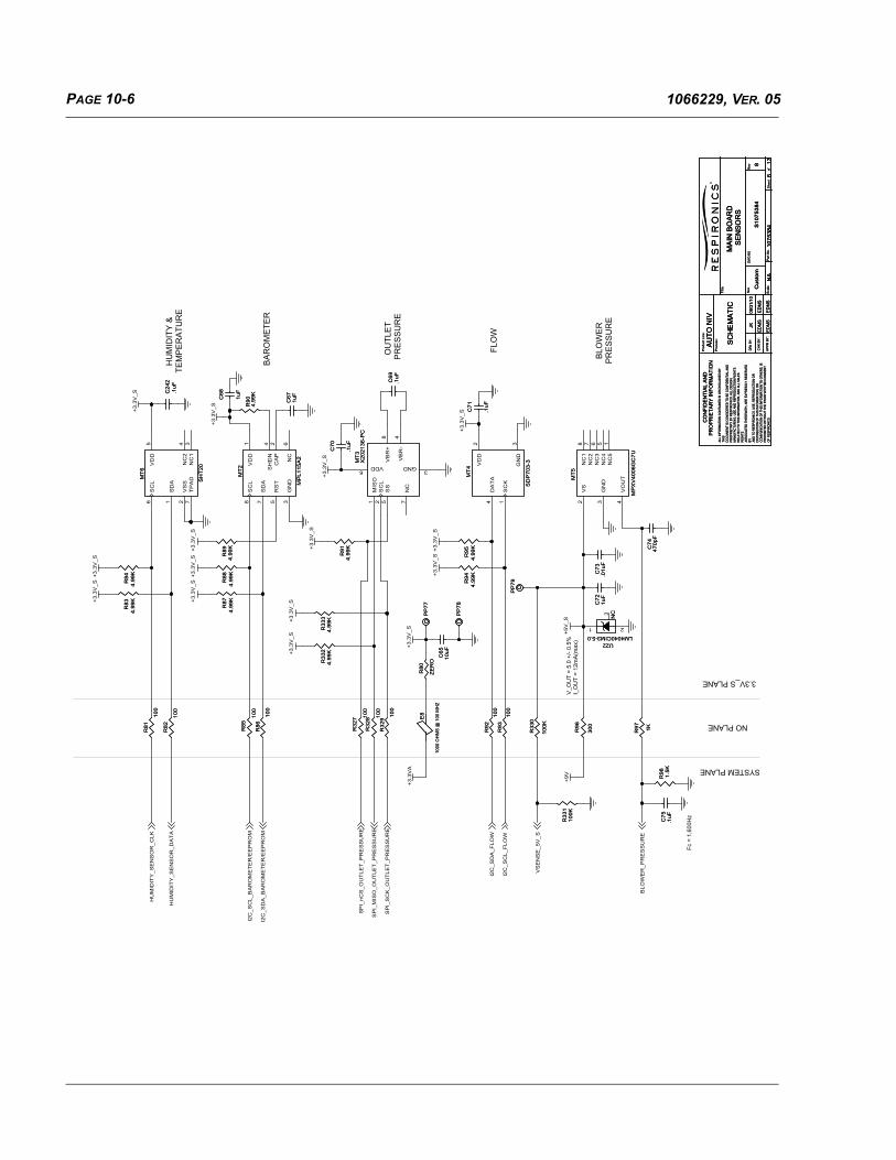
PAGE 10-6 1066229, VER. 05
BLO
WE
R
PR
ES
SU
RE
FLO
W
OU
TLE
TP
RE
SS
UR
E
BA
RO
ME
TER
H
UM
IDIT
Y &
TEM
PE
RA
TUR
E
NO PLANE
3.3V_S PLANE
SYSTEM PLANE
V_O
UT
= 5.
0 +/
- 0.5
%I_
OU
T =
12m
A(m
ax)
Fc =
1,6
00H
z
+3.3
V_S
+3.3
V_S
+3.3
V_S
+3.3
V_S
+3.3
V_S
+3.3
V_S
+5V
_S
+3.3
V_S
+3.3
V_S
+3.3
V_S
+3.3
V_S
+3.3
V_S
+3.3
VA
+3.3
V_S
+9V
+3.3
V_S
+3.3
V_S
+3.3
V_S
BLO
WE
R_P
RE
SS
UR
E
I2C
_SC
L_F
LOW
I2C
_SD
A_F
LOW
I2C
_SC
L_B
AR
OM
ET
ER
/EE
PR
OM
HU
MID
ITY
_SE
NS
OR
_CLK
SP
I_nC
S_O
UT
LET
_PR
ES
SU
RE
SP
I_S
CK
_OU
TLE
T_P
RE
SS
UR
E
SP
I_M
ISO
_OU
TLE
T_P
RE
SS
UR
E
I2C
_SD
A_B
AR
OM
ET
ER
/EE
PR
OM
HU
MID
ITY
_SE
NS
OR
_DA
TA
VS
EN
SE
_5V
_S
Size
Sca
le
DWG
NO
Rev
She
etof
Par
t No.
Title
:AL
L IN
FORM
ATIO
N CO
NTAI
NED
IN O
R DI
SCLO
SED
BYTH
ISDO
CUM
ENT
IS C
ONS
IDER
ED T
O B
E CO
NFID
ENTI
AL A
NDPR
OPR
IETA
RY B
Y RE
SPIR
ONI
CS. A
LL D
ESIG
N,M
ANUF
ACTU
RING
, USE
AND
REP
RODU
CTIO
N RI
GHT
SRE
LATE
D TO
THI
S IN
FORM
ATIO
N, A
ND A
LL S
ALES
RIG
HTS
ASSO
CIAT
ED T
HERE
WIT
H, A
RE E
XPRE
SSLY
RES
ERVE
DBY AN
D TO
RES
PIRO
NICS
. USE
, REP
RODU
CTIO
N O
RDI
STIR
BUTI
ON
OF
THIS
INFO
RMAT
ION,
OR
COM
MUN
ICAT
ION
OF
THIS
INFO
RMAT
ION
TO O
THER
S, IS
PRO
HIBI
TED
WIT
HOUT
THE
PRI
OR
WRI
TTEN
CO
NSEN
TO
F RE
SPIR
ONI
CS.
CO
NFI
DE
NTI
AL
AN
DP
rodu
ct L
ine:
Pro
cess
:
SC
HE
MA
TIC
DRN
BY:
CH
K B
Y:
AP
PR
BY
:
PR
OP
RIE
TAR
Y IN
FOR
MA
TIO
N
Cus
tom
MA
IN B
OA
RD
SE
NS
OR
S
JK
EDM
S
AU
TO N
IV
EDM
S
EDM
S
08/3
1/10
EDM
SN
A
S10
7538
4
1075
384
6138
R91
4.99
KR
914.
99K
R83
4.99
KR
834.
99K
E8
1000
OH
MS
@ 1
00 M
HZ
E8
1000
OH
MS
@ 1
00 M
HZ
R33
34.
99K
R33
34.
99K
R92
100
R92
100
C70
.1uF
C70
.1uF
C24
2.1
uFC
242
.1uF
R32
9
100
R32
9
100
MT
6
SH
T20
MT
6
SH
T20
SD
A1
SC
L6
VS
S2
VD
D5
NC
24
NC
13
TP
AD
7
R94
4.99
KR
944.
99K C
73.0
1uF
C73
.01u
F
MT
4
SD
P70
3-3
MT
4
SD
P70
3-3
DA
TA
4
SC
K1
VD
D2
GN
D3
C68
1uF
C68
1uF
PP
77P
P77
C71
.1uF
C71
.1uF
PP
79P
P79
MT
5
MP
XV
4006
GC
7U
MT
5
MP
XV
4006
GC
7U
GN
D3
VO
UT
4
VS
2
NC
27
NC
18
NC
36
NC
45
NC
51
R97 1KR97 1K
C75
.1uF
C75
.1uF
R80
ZE
RO
R80
ZE
RO
MT
3X
2021
36-P
CM
T3
X20
2136
-PC
NC
7
SS
5
MIS
O1
SC
L2
VB
R+
8
VDD6
GND3
VB
R-
4
R98 1.5K
R98 1.5K
C72
1uF
C72
1uF
R33
0
100K
R33
0
100K
C69
.1uF
C69
.1uF
R93
100
R93
100
C65
10uF
C65
10uF
R89
4.99
KR
894.
99K
R88
4.99
KR
884.
99K
R95
4.99
KR
954.
99K
R86
100
R86
100
R32
8 100
R32
8 100
R85
100
R85
100
C67
1uF
C67
1uF
R32
7 100
R32
7 100
PP
78P
P78
C74
470p
FC
7447
0pF
R33
110
0KR
331
100K
R87
4.99
KR
874.
99K
NC
U22LM4040CIM3-5.0
NC
U22LM4040CIM3-5.0
1 2
3
R90
4.99
KR
904.
99K
R84
4.99
KR
844.
99K
R82
100
R82
100
MT
2
MP
L115
A2
MT
2
MP
L115
A2
GN
D3
SH
DN
4
CA
P2
SD
A7
SC
L8
NC
6
RS
T5
VD
D1
R81
100
R81
100
R33
24.
99K
R33
24.
99K
R96
300
R96
300

PAGE 10-71066229, VER. 05
SY
STE
M G
RO
UN
D
P
LAN
E
SYSTEM GROUND PLANE
NO PLANE
POWER GROUND PLANE
NO
PLA
NE
>=4m
m C
reep
age
>=2.
5mm
Cle
aran
ce
NURSE CALLMODULAR JACK
ACCESSORYSD
CA
RD
D3
CM
D
CLK D
0
D1
D2
PR
OT
EC
T
DE
TE
CT
GN
D
3.3V
GN
D
GN
D
SH
ELL
SH
ELL
+3.3
VD
+3.3
VD
+3.3
VD
+3.3
VD
+3.3
VD
+3.3
VD
V_B
US
+3.3
VD
+3.3
VD
PS
PS
PS
PS
PS
PS
V_B
OO
ST
+9V
+3.3
VD
SD
_D3
SD
_D0
SD
_CM
D
SD
_CLK
SD
_D1
SD
_D2
UA
RT
1_T
X
UA
RT
1_R
X
nNU
RS
E_C
ALL
SD
_DE
TE
CT
SD
_IN
SE
RT
SD
_WR
_PR
OT
EC
T
Size
Sca
le
DWG
NO
Rev
She
etof
Par
t No.
Title
:AL
L IN
FORM
ATIO
N CO
NTAI
NED
IN O
R DI
SCLO
SED
BYTH
ISDO
CUM
ENT
IS C
ONS
IDER
ED T
O B
E CO
NFID
ENTI
AL A
NDPR
OPR
IETA
RY B
Y RE
SPIR
ONI
CS. A
LL D
ESIG
N,M
ANUF
ACTU
RING
, USE
AND
REP
RODU
CTIO
N RI
GHT
SRE
LATE
D TO
THI
S IN
FORM
ATIO
N, A
ND A
LL S
ALES
RIG
HTS
ASSO
CIAT
ED T
HERE
WIT
H, A
RE E
XPRE
SSLY
RES
ERVE
DBY AN
D TO
RES
PIRO
NICS
. USE
, REP
RODU
CTIO
N O
RDI
STIR
BUTI
ON
OF
THIS
INFO
RMAT
ION,
OR
COM
MUN
ICAT
ION
OF
THIS
INFO
RMAT
ION
TO O
THER
S, IS
PRO
HIBI
TED
WIT
HOUT
THE
PRI
OR
WRI
TTEN
CO
NSEN
TO
F RE
SPIR
ONI
CS.
CO
NFI
DE
NTI
AL
AN
DP
rodu
ct L
ine:
Pro
cess
:
SC
HE
MA
TIC
DRN
BY:
CH
K B
Y:
AP
PR
BY
:
PR
OP
RIE
TAR
Y IN
FOR
MA
TIO
N
Cus
tom
MA
IN B
OA
RD
SD
CA
RD
, AC
CY
, & N
UR
SE
CA
LLJK
EDM
S
AU
TO N
IV
EDM
S
EDM
S
08/3
1/10
EDM
SN
A
S10
7538
4
1075
384
7138
Q23
BS
S12
3Q
23B
SS
123
3
1
2
PP
53P
P53
CR20ESD5Z5.0T1G
CR20ESD5Z5.0T1G
R14
010
KR
140
10K
C89
1000
pFC
8910
00pF
E21
1000
OH
MS
@ 1
00 M
HZ
E21
1000
OH
MS
@ 1
00 M
HZ
J7
CO
NN
SD
CA
RD
TO
P M
OU
NT
J7
CO
NN
SD
CA
RD
TO
P M
OU
NT
1 2 3 4 5 6 7 8 9 10 11 12 13 14
R13
910
KR
139
10K
R15
624
9KR
156
249K
C88
1000
pFC
8810
00pF
R13
0
100
R13
0
100
CR65ESD5Z12T1G
CR65ESD5Z12T1G
C87
1000
pFC
8710
00pF
R15
510
0KR
155
100K
R14
8
100
R14
8
100
PP
129
PP
129
C84
.1uF
C84
.1uF
R14
9
1KR14
9
1K
R14
7
100
R14
7
100
E20
1000
OH
MS
@ 1
00 M
HZ
E20
1000
OH
MS
@ 1
00 M
HZ
E10
1000
OH
MS
@ 1
00 M
HZ
E10
1000
OH
MS
@ 1
00 M
HZ
CR17ESD5Z5.0T1G
CR17ESD5Z5.0T1G
R13
2
100
R13
2
100
C85
4.7u
FC
854.
7uF
Q20
BS
S12
3Q20
BS
S12
3
3
1
2
E13
1000
OH
MS
@ 1
00 M
HZ
E13
1000
OH
MS
@ 1
00 M
HZ
R14
210
KR
142
10K
RL1
V23
026A
1004
RL1
V23
026A
1004
N-C
L1
IN-
5
IN+
2
CO
MM
ON
3
N-O
P6
NC
4
E18
1000
OH
MS
@ 1
00 M
HZ
E18
1000
OH
MS
@ 1
00 M
HZ
R14
449
9KR
144
499K
E9
1000
OH
MS
@ 1
00 M
HZ
E9
1000
OH
MS
@ 1
00 M
HZ
E17
1000
OH
MS
@ 1
00 M
HZ
E17
1000
OH
MS
@ 1
00 M
HZ
R13
5
100
R13
5
100
R13
1
ZE
RO
R13
1
ZE
RO
R13
4
100
R13
4
100
R13
810
KR
138
10K
R13
6
100
R13
6
100
CR19ESD5Z5.0T1G
CR19ESD5Z5.0T1G
PP
65P
P65
E16
1000
OH
MS
@ 1
00 M
HZ
E16
1000
OH
MS
@ 1
00 M
HZ
R14
510
KR
145
10K
CR
22M
BR
X14
0C
R22
MB
RX
140
R13
7
100
R13
7
100
E15
1000
OH
MS
@ 1
00 M
HZ
E15
1000
OH
MS
@ 1
00 M
HZ
R14
310
KR
143
10K
E24
1000
OH
MS
@ 1
00 M
HZ
E24
1000
OH
MS
@ 1
00 M
HZ
PX
1
CONN M 7 PIN EDGE FINGERS
PX
1
CONN M 7 PIN EDGE FINGERS
1 2 3 4 5 6 7
R14
110
KR
141
10K
J9J91234
R12
9
100
R12
9
100
E23
1000
OH
MS
@ 1
00 M
HZ
E23
1000
OH
MS
@ 1
00 M
HZ
C29
210
uFC
292
10uF
R13
3
100
R13
3
100
E22
1000
OH
MS
@ 1
00 M
HZ
E22
1000
OH
MS
@ 1
00 M
HZ
C86 1u
FC
86 1uF
PP
66P
P66
R15
010
KR
150
10K
CR21ESD5Z5.0T1G
CR21ESD5Z5.0T1G
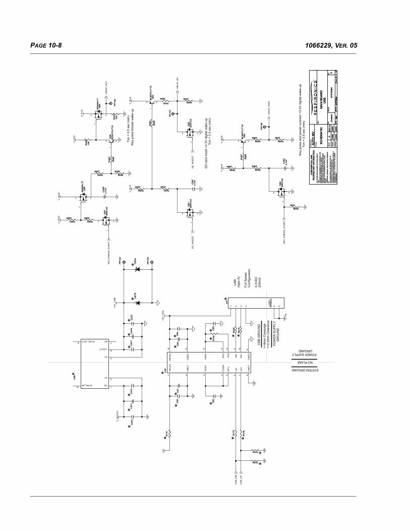
PAGE 10-8 1066229, VER. 05
>=4m
m C
reep
age
>=2.
5mm
Cle
aran
ce
US
B G
RO
UN
D
PO
WE
R S
UP
PLY
G
RO
UN
D
SYSTEM GROUND
POWER SUPPLY GROUND
NO PLANE
Key
pre
ss b
low
er w
ake-
upTo
n =
3.5
sec
(min
)
SD
car
d in
sert
+3.3
V d
igita
l wak
e-up
Ton
= 3.
5 se
c (m
in)
Ton
= 3.
5 se
c (m
in)
Key
pre
ss a
nd p
ower
con
nect
+3.
3V d
igita
l wak
e-up
US
B
(type
A)
Full
Spe
edC
onfig
urat
ion
5.0V
DC
200m
A
*
* *
**
**
**
**
**
*
**
*
* *
**
* *
**
PS
+5V
+5V
_US
B
+5V
_US
B
V_B
US
V_B
US
+3.
3VD
+3.
3VD
V_B
US
V_B
US
V_B
US
V_B
US
V_B
OO
ST
US
B_D
M
US
B_D
P
KE
Y_P
RE
SS
_ST
AR
TW
KU
P_K
EY
SD
_IN
SE
RT
SD
_IN
SE
RT
WK
UP
_PW
R
WK
UP
_SD
KE
Y_P
RE
SS
_ST
AR
T
Size
Sca
le
DWG
NO
Rev
She
etof
Par
t No.
Title
:AL
L IN
FORM
ATIO
N CO
NTAI
NED
IN O
R DI
SCLO
SED
BYTH
ISDO
CUM
ENT
IS C
ONS
IDER
ED T
O B
E CO
NFID
ENTI
AL A
NDPR
OPR
IETA
RY B
Y RE
SPIR
ONI
CS. A
LL D
ESIG
N,M
ANUF
ACTU
RING
, USE
AND
REP
RODU
CTIO
N RI
GHT
SRE
LATE
D TO
THI
S IN
FORM
ATIO
N, A
ND A
LL S
ALES
RIG
HTS
ASSO
CIAT
ED T
HERE
WIT
H, A
RE E
XPRE
SSLY
RES
ERVE
DBY AN
D TO
RES
PIRO
NICS
. USE
, REP
RODU
CTIO
N O
RDI
STIR
BUTI
ON
OF
THIS
INFO
RMAT
ION,
OR
COM
MUN
ICAT
ION
OF
THIS
INFO
RMAT
ION
TO O
THER
S, IS
PRO
HIBI
TED
WIT
HOUT
THE
PRI
OR
WRI
TTEN
CO
NSEN
TO
F RE
SPIR
ONI
CS.
CO
NFI
DE
NTI
AL
AN
DP
rodu
ct L
ine:
Pro
cess
:
SC
HE
MA
TIC
DRN
BY:
CH
K B
Y:
AP
PR
BY
:
PR
OP
RIE
TAR
Y IN
FOR
MA
TIO
N
Cus
tom
MA
IN B
OA
RD
US
BJK
EDM
S
AU
TO N
IV
EDM
S
EDM
S
08/3
1/10
EDM
SN
A
S10
7538
4
1075
384
8138
Q59
BC
847C
LT1G
Q59
BC
847C
LT1G
1
3 2
R153 R153
C93
C93
U16
U16 VB
US
11
SP
D13
GN
D1
8
VD
D2
14
GN
D2
15
PIN
12
UD
-6
DD
+10
GN
D2
9
UD
+7
GN
D1
2
PD
EN
4
VD
D1
3
SP
U5
VB
US
216
DD
-11
R499
249K
R499
249K
PP
134
PP
134
C28
14.
7uF
C28
14.
7uF
Q63
BC
857C
LT1G
Q63
BC
857C
LT1G
1
2 3
C27
0C
270
R484
499K
R484
499K
PP
136
PP
136
Q57
BS
S12
3Q
57B
SS
123
3
1
2
C92
C92
Q58
BS
S84
LT1
Q58
BS
S84
LT1
3
1
2
PP
138
PP
138
R17
5R
175
C27
5C
275
CR
34C
R34
C95
C95
R482
249K
R482
249K
R493
499K
R493
499K
PP
135
PP
135
Q62
BS
S12
3Q
62B
SS
123
3
1
2
Q64
BS
S12
3Q
64B
SS
123
3
1
2R490
499K
R490
499K
PP
137
PP
137
R496
249K
R496
249K
C27
1C
271
R48
610
KR
486
10K
Q65
BC
857C
LT1G
Q65
BC
857C
LT1G
1
2 3
R15
2R
152
R49
2
499K
R49
2
499K
C90
C90
R495
499K
R495
499K
C91
C91
C94
C94
R488
100K
R488
100K
Q60
BS
S84
LT1
Q60
BS
S84
LT1
3
1
2
Q61
BS
S12
3Q
61B
SS
123
3
1
2
U28
U28
VS1
SYNC_OUT8
SYNC_IN14
+VOUT6
NC7
0V2
0V5
R21
5R
215
R483
249K
R483
249K
R481
249K
R481
249K
R498
499K
R498
499K
R15
1R
151
C27
6C
276
R491
249K
R491
249K
CR
79C
R79
SH
IELD
J10
SH
IELD
J10
1 2 3 4 5 6
R20
5R
205
C28
24.
7uF
C28
24.
7uF
R48
5
499K
R48
5
499K
R17
6R
176
C28
04.
7uF
C28
04.
7uF
R48
710
KR
487
10K
R49
7
499K
R49
7
499K
C27
2C
272
R494
249K
R494
249K
C27
7C
277
R154 R154

PAGE 10-91066229, VER. 05
SYSTEM GROUND PLANE
POWER GROUND PLANE
NO PLANE
HUMIDIFIER AND HEATED HOSE
*
+3.3
VD
PS
PS
PS
+3.3
VD
PS
V_B
US
V_B
US
PS
PS
PS
PS
PS
+3.3
VD
HE
AT
_H
OS
E_P
WM
HE
AT
_H
OS
E_T
EM
P
HU
MID
IFIE
R_P
LA
TE
_T
EM
P
HE
AT
_H
OS
E_C
UR
RE
NT
HU
MID
IFIE
R_S
PA
RE
HU
MID
IFIE
R_P
WM
Size
Sca
le
DW
G N
OR
ev
She
etof
Par
t No.
Titl
e:AL
L IN
FOR
MAT
ION
CO
NTA
INED
IN O
R D
ISC
LOSE
D B
YTH
ISD
OC
UM
ENT
IS C
ON
SID
ERED
TO
BE
CO
NFI
DEN
TIAL
AN
DPR
OPR
IETA
RY
BY R
ESPI
RO
NIC
S. A
LL D
ESIG
N,
MAN
UFA
CTU
RIN
G, U
SE A
ND
REP
RO
DU
CTI
ON
RIG
HTS
REL
ATED
TO
TH
IS IN
FOR
MAT
ION
, AN
D A
LL S
ALES
RIG
HTS
ASSO
CIA
TED
TH
EREW
ITH
, AR
E EX
PRES
SLY
RES
ERVE
DBY AN
D T
O R
ESPI
RO
NIC
S. U
SE, R
EPR
OD
UC
TIO
N O
RD
ISTI
RBU
TIO
N O
F TH
IS IN
FOR
MAT
ION
, OR
CO
MM
UN
ICAT
ION
OF
THIS
INFO
RM
ATIO
N T
O O
THER
S, IS
PRO
HIB
ITED
WIT
HO
UT
THE
PRIO
R W
RIT
TEN
CO
NSE
NT
OF
RES
PIR
ON
ICS.CO
NF
IDE
NT
IAL
AN
DP
rodu
ct L
ine:
Pro
cess
:
SC
HE
MA
TIC
DR
N B
Y:
CH
K B
Y:
AP
PR
BY
:
PR
OP
RIE
TA
RY
INF
OR
MA
TIO
N
Cust
om
MA
IN B
OA
RD
HU
MID
IFIE
R &
HE
AT
ED
HO
SE
JK
ED
MS
AU
TO
NIV
ED
MS
ED
MS
08/3
1/10
ED
MS
NA
S1
07
53
84
10
75
38
49
13
8Si
ze
Sca
le
DW
G N
OR
ev
She
etof
Par
t No.
Titl
e:AL
L IN
FOR
MAT
ION
CO
NTA
INED
IN O
R D
ISC
LOSE
D B
YTH
ISD
OC
UM
ENT
IS C
ON
SID
ERED
TO
BE
CO
NFI
DEN
TIAL
AN
DPR
OPR
IETA
RY
BY R
ESPI
RO
NIC
S. A
LL D
ESIG
N,
MAN
UFA
CTU
RIN
G, U
SE A
ND
REP
RO
DU
CTI
ON
RIG
HTS
REL
ATED
TO
TH
IS IN
FOR
MAT
ION
, AN
D A
LL S
ALES
RIG
HTS
ASSO
CIA
TED
TH
EREW
ITH
, AR
E EX
PRES
SLY
RES
ERVE
DBY AN
D T
O R
ESPI
RO
NIC
S. U
SE, R
EPR
OD
UC
TIO
N O
RD
ISTI
RBU
TIO
N O
F TH
IS IN
FOR
MAT
ION
, OR
CO
MM
UN
ICAT
ION
OF
THIS
INFO
RM
ATIO
N T
O O
THER
S, IS
PRO
HIB
ITED
WIT
HO
UT
THE
PRIO
R W
RIT
TEN
CO
NSE
NT
OF
RES
PIR
ON
ICS.CO
NF
IDE
NT
IAL
AN
DP
rodu
ct L
ine:
Pro
cess
:
SC
HE
MA
TIC
DR
N B
Y:
CH
K B
Y:
AP
PR
BY
:
PR
OP
RIE
TA
RY
INF
OR
MA
TIO
N
Cust
om
MA
IN B
OA
RD
HU
MID
IFIE
R &
HE
AT
ED
HO
SE
JK
ED
MS
AU
TO
NIV
ED
MS
ED
MS
08/3
1/10
ED
MS
NA
S1
07
53
84
10
75
38
49
13
8
C64
1000pF
C64
1000pF
E7
50 O
HM
S @
100 M
Hz
E7
50 O
HM
S @
100 M
Hz
C1
01
10
00
pF
C1
01
10
00
pF
CR50ESD5Z5.0T1G
CR50ESD5Z5.0T1G
PP
85
PP
85
PP
87
PP
87
R2
65
10
0K
R2
65
10
0K
CR23SMAJ30ACR23
SMAJ30A
P5
CO
NN
-TH
M 6
PIN
RA
3.9
6m
m
P5
CO
NN
-TH
M 6
PIN
RA
3.9
6m
m
1 2 3 4 5 6
PP
81
PP
81
C9
61
uF
C9
61
uF
C9
8.1
uF
C9
8.1
uF
PP
83
PP
83
CR67SMAJ30A
CR67SMAJ30A
E6
1000 O
HM
S @
100 M
HZ
E6
1000 O
HM
S @
100 M
HZ
R1
61
1.5
K
R1
61
1.5
K
PP
82
PP
82
76
8
Q12
BS
C084P
03N
S3E
76
8
Q12
BS
C084P
03N
S3E
5
4
123
76
8
Q21
BS
C084P
03N
S3E
76
8
Q21
BS
C084P
03N
S3E
5
4
123
R74
1.5
K
R74
1.5
K
E26
50 O
HM
S @
100 M
Hz
E26
50 O
HM
S @
100 M
Hz
C61
.1uF
C61
.1uF
CR68ESD5Z5.0T1G
CR68ESD5Z5.0T1G
R2
61
10
K
R2
61
10
K
+C
59
47uF
+C
59
47uF
PP
86
PP
86
C180
10
00
pF
C180
10
00
pF
R1
63
24.9
KR
16
324.9
K
Q11
BS
S123Q
11
BS
S123
3
1
2
R75
100K
R75
100K
R2
63
1 2W
R2
63
1 2W
R264
6.4
9K
R264
6.4
9K
E69
1000 O
HM
S @
100 M
HZ
E69
1000 O
HM
S @
100 M
HZ
R1
64
24
9K
R1
64
24
9K
CR13ESD5Z5.0T1G
CR13ESD5Z5.0T1G
R78
6.4
9K
R78
6.4
9K
R79
100K
R79
100K
C1
00
C1
00
CR12ESD5Z5.0T1G
CR12ESD5Z5.0T1G
C1
81
.1uF
C1
81
.1uF
R2
62
10
0K
R2
62
10
0K
Q22
BS
S123
Q22
BS
S123
3
1
2
R73
4.9
9K
R73
4.9
9K
R1
62
10
0K
R1
62
10
0K
E25
1000 O
HM
S @
100 M
HZ
E25
1000 O
HM
S @
100 M
HZ
C60
.1uF
C60
.1uF
CR
69
MM
SZ
15T
1G
15V
CR
69
MM
SZ
15T
1G
15V
C63
1000pF
C63
1000pF
R1
60
4.9
9K
R1
60
4.9
9K
PP
84
PP
84
CR
70
MM
SZ
15T
1G
15
V
CR
70
MM
SZ
15T
1G
15
V
PP
80
PP
80
PP
88
PP
88
C58
1uF
C58
1uF
E4
50 O
HM
S @
100 M
Hz
E4
50 O
HM
S @
100 M
Hz

PAGE 10-10 1066229, VER. 05
VC
AP
_1V
CA
P_2
8D
DV
5D
DV
4D
DV
3D
DV
2D
DV
1D
DV
VD
D7
31D
DV
01D
DV
9D
DV
6D
DV
VD
D12
41D
DV
11D
DV
VD
D15
VR
EF
+
JTA
G
FREE MASTER COMM
**
VD
D12
VD
D13
41D
DV
11D
DV
VD
D15
5D
DV
2D
DV
1D
DV
VD
D4
8D
DV
3D
DV
01D
DV
7D
DV
6D
DV
VD
D9
VD
D_S
A
/TIM09_CH02
*
ON
LY P
OP
ULA
TE
EIT
HE
R R
25 O
R R
71
DE
BU
G2
DE
BU
G1
DE
BU
G0
JTD
O
JTD
I
HW
_CO
NF
IG_2
HW
_CO
NF
IG_1
UA
RT
2_T
XU
AR
T2_
RX
nRESET
JTMS
JTC
K
nJT
RS
T
JTD
O
JTM
S
JTC
KJT
DI
nJT
RS
T
UA
RT
1_R
X
nRE
SE
T
VC
AP
1
+3.3
VD
+3.3
VD
+3.3
VD
+3.3
VD
VC
AP
1
+3.3
VD
+3V
_RE
F
+3.3
DA
+3.3
VD
VC
AP
2
+3.3
VD
+3.3
VD
+3.3
VD
+3.3
VD
+3.3
VD
+3.3
VD
+3.3
VD
+3.3
VD
+3.3
VD
+3.3
VD
+3.3
VD
+3.3
VD
+3.3
VD
+3.3
VD
+3.3
VD
+3V
_RE
F
VC
AP
2
+3.3
VD
+3.3
VD
+3.3
VD
+3.3
VD
+3.3
VD
+3.3
VD
+3.3
VD
+3.3
VD
+3.3
VD
+3.3
VD
+3.3
VD
+3.3
VD
+3.3
VD
+3.3
VD
+3.3
VD
+3.3
VD
+3.3
VD
+3.3
VD
+3.3
VA
+3.3
DA
+3.3
VD
+3.3
VD
UART1_TX
A0A1A2A3A4A5
COMM_PIC
VS
EN
SE
_AC
VS
EN
SE
_Pb
VS
EN
SE
_SP
AR
EV
SE
NS
E_P
FV
SE
NS
E_5
V_S
CU
RR
EN
T_S
YS
TE
M
CU
RR
EN
T_C
CU
RR
EN
T_B
CU
RR
EN
T_A
VS
EN
SE
_MO
TO
R
SP
I_M
ISO
_FLA
SH
I2C
_SD
A_F
LOW
HU
MID
IFIE
R_P
LAT
E_T
EM
P
MO
TO
R_T
EM
P
HE
AT
_HO
SE
_TE
MP
BLO
WE
R_P
RE
SS
UR
E
D4
D5
D6
D7
D8
D9
D10
D11
D12
A7
A8
A9
A10
A11
I2C
_SD
A_B
AR
OM
ET
ER
/EE
PR
OM
A6
D13D14D15
D0D1
HUMIDITY_SENSOR_DATA
UART1_RX
SD
_D2
SD
_D3
SD
_CLK
A12A13A14A15
D2
D3
SD
_CM
D
nOE
nWE
SR
AM
_nC
ED
R_n
CE
DR
_TE
Li_S
DA
nLB
nUB
LCD
_nR
ST
A18
SP
I_nC
S_F
LAS
H
DR
_nR
ST
LED
_KE
YP
AD
Li_S
CL
PW
M_A
HP
WM
_BH
PW
M_C
H
nSW_LEFTnSW_DOWN
nSW_UPnSW_RIGHT
DITHER
nPF_ENABLEBUZZER_uP
nLE
D_A
C_P
RE
SE
NT
I2C
_SC
L_F
LOW
SP
I_S
CK
_FLA
SH
SP
I_M
OS
I_F
LAS
H
HE
AT
_HO
SE
_PW
MI2
C_S
CL_
BA
RO
ME
TE
R/E
EP
RO
M
nLE
D_R
ED
_uP
nLE
D_Y
ELL
OW
nVA
LVE
_EN
AB
LE
nAUDIO_PAUSE
SPI_nCS_OUTLET_PRESSURESPI_SCK_OUTLET_PRESSURESPI_MISO_OUTLET_PRESSURE
A16A17
HUMIDITY_SENSOR_CLK
HUMIDIFIER_PWM
SD_D0SD_D1
DR_CLK
USB_DMUSB_DP
PWM_ALPWM_BLPWM_CLSD_DETECTSD_WR_PROTECT
D[0
:15]
A[0
:17]
nVA
LVE
_ER
RO
R
LCD
_nO
N
VS
EN
SE
_WA
TT
nNURSE_CALL
nSTART/STOP
HE
AT
_HO
SE
_CU
RR
EN
T
Li_S
PA
RE
Pb_
DIS
AB
LE
HUMIDIFIER_SPARE
nMO
TO
R_F
AU
LT
WKUP_KEY
nMO
TO
R_O
VE
R_C
UR
RE
NT
nSLE
EP
LED
_ST
AR
T/S
TO
P
Size
Sca
le
DWG
NO
Rev
She
etof
Par
t No.
Title
:AL
L IN
FORM
ATIO
N CO
NTAI
NED
IN O
R DI
SCLO
SED
BYTH
ISDO
CUM
ENT
IS C
ONS
IDER
ED T
O B
E CO
NFID
ENTI
AL A
NDPR
OPR
IETA
RY B
Y RE
SPIR
ONI
CS. A
LL D
ESIG
N,M
ANUF
ACTU
RING
, USE
AND
REP
RODU
CTIO
N RI
GHT
SRE
LATE
D TO
THI
S IN
FORM
ATIO
N, A
ND A
LL S
ALES
RIG
HTS
ASSO
CIAT
ED T
HERE
WIT
H, A
RE E
XPRE
SSLY
RES
ERVE
DBY AN
D TO
RES
PIRO
NICS
. USE
, REP
RODU
CTIO
N O
RDI
STIR
BUTI
ON
OF
THIS
INFO
RMAT
ION,
OR
COM
MUN
ICAT
ION
OF
THIS
INFO
RMAT
ION
TO O
THER
S, IS
PRO
HIBI
TED
WIT
HOUT
THE
PRI
OR
WRI
TTEN
CO
NSEN
TO
F RE
SPIR
ONI
CS.
CO
NFI
DE
NTI
AL
AN
DP
rodu
ct L
ine:
Pro
cess
:
SC
HE
MA
TIC
DRN
BY:
CH
K B
Y:
AP
PR
BY
:
PR
OP
RIE
TAR
Y IN
FOR
MA
TIO
N
Cus
tom
MA
IN B
OA
RD
MIC
RO
CO
NTR
OLL
ER
JK
EDM
S
AU
TO N
IV
EDM
S
EDM
S
08/3
1/10
EDM
SN
A
S10
7538
4
1075
384
10138
C16
210
00pF
C16
210
00pF
PP
107
PP
107
C14
54.
7uF
C14
54.
7uF
B1
CR-1632/G1AN
B1
CR-1632/G1AN
C15
9.1
uFC
159
.1uF
R22
6
100K
R22
6
100K
R20
910
0KR
209
100K
R21
7
1KR21
7
1K
C15
8.1
uFC
158
.1uF
R20
8R
208
C15
4.1
uFC
154
.1uF
R412
1K
R412
1K
PP
104
PP
104
PP
119
PP
119
C13
7.1
uFC
137
.1uF
C13
9.1
uFC
139
.1uF
C19
510
00pF
C19
510
00pF
P16
CO
NN
-TH
M 4
PIN
2.5
4mm
P16
CO
NN
-TH
M 4
PIN
2.5
4mm
2 4
1 3
C15
6.1
uFC
156
.1uF
R20
6R
206
PP
101
PP
101
C20
210
00pF
C20
210
00pF
R18
3
10K
R18
3
10K
C13
4.1
uFC
134
.1uF
C17
14.
7uF
C17
14.
7uF
PP
102
PP
102
PP
105
PP
105
C19
210
00pF
C19
210
00pF
C17
2.1
uFC
172
.1uF
C10
4.1
uFC
104
.1uF
C14
2.1
uFC
142
.1uF
C15
0
27pF
C15
0
27pF
R21
1
750
R21
1
750
R22
2
10K
R22
2
10K
PP
100
PP
100
C12
9.1
uFC
129
.1uF
C12
6.1
uFC
126
.1uF
C12
5.1
uFC
125
.1uF
R23
615
0R
236
150
C16
8.1
uFC
168
.1uF
R22
3
10K
R22
3
10K
C12
7.1
uFC
127
.1uF
R21
9
1KR21
9
1K
C19
410
00pF
C19
410
00pF
C20
010
00pF
C20
010
00pF
C16
010
00pF
C16
010
00pF
PP
99P
P99
C13
5.1
uFC
135
.1uF
U21
B
ST
M32
F20
3IG
T6
U21
B
ST
M32
F20
3IG
T6
VS
S_1
314
VD
D_1
315
VS
SA
37
VR
EF
+38
VD
DA
39
VS
S_5
22
VD
D_5
23
VD
D_1
82
VC
AP
_181
VD
D_7
72
VS
S_7
71
VD
D_6
62
VS
S_6
61V
DD
_449
VS
S_4
48V
DD
_212
7V
SS
_212
6
VC
AP
_212
5
VD
D_9
114
VS
S_9
113
VD
D_8
103
VS
S_8
102
VD
D_1
491
VS
S_1
490
VS
S_1
513
5
VD
D_1
513
6
VS
S_1
014
8
VD
D_1
014
9V
SS
_11
158
VD
D_1
115
9
VD
D_S
A17
1
VD
D_3
172
TP
AD
177
VD
D_1
236
Y2
32.7
68kH
z
Y2
32.7
68kH
z
C16
5.1
uFC
165
.1uF
C20
110
00pF
C20
110
00pF
R21
0
10K
R21
0
10K
C16
4.1
uFC
164
.1uF
PP
106
PP
106
PP
117
PP
117
PP
114
PP
114
C19
110
00pF
C19
110
00pF
R24
0
100K
R24
0
100K
C14
86.
8pF
C14
86.
8pF
R22
4
10K
R22
4
10K
C15
21u
FC
152
1uF
C15
7.1
uFC
157
.1uF
C14
9
27pF
C14
9
27pF
C14
11u
FC
141
1uF
C20
510
00pF
C20
510
00pF
C15
5.1
uFC
155
.1uF
R20
710
0KR
207
100K
R21
349
.9R
213
49.9
R71
ZE
RO
R71
ZE
RO
C16
6.1
uFC
166
.1uF
R23
749
9R
237
499 CR45
AMBER
CR45
AMBER
P15
CO
NN
-TH
M 4
PIN
2.5
4mm
P15
CO
NN
-TH
M 4
PIN
2.5
4mm
2 4 6 8
1 53 7
C19
810
00pF
C19
810
00pF
C12
44.
7uF
C12
44.
7uF
R23
510
0R
235
100
R21
610
KR
216
10K
PP
115
PP
115
C16
34.
7uF
C16
34.
7uF CR44
GREEN
CR44
GREEN
R22
5
10K
R22
5
10K
C13
8.1
uFC
138
.1uF
PP
108
PP
108
C13
0.1
uFC
130
.1uF
C13
6.1
uFC
136
.1uF
R21
249
.9R
212
49.9
C19
910
00pF
C19
910
00pF
U21
AS
TM
32F
203I
GT
6U
21A
ST
M32
F20
3IG
T6
PH344PH243
PA0/WKUP40
PC3/ADC123_IN1335PC2/ADC123_IN1234PC1/ADC123_IN1133PC0/ADC123_IN1032nRST31
PF9/ADC3_IN727
PH1-OSC_OUT30
PF8/ADC3_IN626
PH0-OSC_IN29
PF7/ADC3_IN525
PF10/ADC3_IN828
PF6/ADC3_IN424
PI1113
PC13-TAMPER1-RTC8
VBAT6
PF5/FSMC_A521
PI911
PF1/FSMC_A117
PF4/FSMC_A420
PF0/FSMC_A016
PF3/FSMC_A319
PI1012
PC14-OSC32_IN9
PI8-TAMPER2-RTC7
PE65
PF2/FSMC_A218
PE43
PE54
PC15-OSC32_OUT10
PE32PE21
PA1/ADC123_IN141
PA2/ADC123_IN242
PH
4/I2
C2_
SC
L45
PH
5/I2
C2_
SD
A46
PA
3/IA
DC
123_
IN3
47
PA
4/D
AC
1_O
UT
50P
A5/
SP
I1_S
CK
51P
A6/
SP
I1_M
ISO
52P
A7/
SP
I1_M
OS
I53
PC
4/A
DC
12_I
N14
54P
C5/
AD
C12
_IN
1555
PB
0/A
DC
12_I
N8
56P
B1/
AD
C12
_IN
957
PB
2/B
OO
T1
58P
F11
59P
F12
/FS
MC
_A6
60
PF
13/F
SM
C_A
763
PF
14/F
SM
C_A
864
PF
15/F
SM
C_A
965
PG
0/F
SM
C_A
1066
PG
1/F
SM
C_A
1167
PE
7/F
SM
C_D
468
PE
8/F
SM
C_D
569
PE
9/F
SM
C_D
670
PE
10/F
SM
C_D
773
PE
11/F
SM
C_D
874
PE
12/F
SM
C_D
975
PE
13/F
SM
C_D
1076
PE
14/F
SM
C_D
1177
PE
15/F
SM
C_D
1278
PB
10/U
SA
RT
03_T
X79
PB
11/U
SA
RT
03_R
X80
PH
683
PH
7/I2
C3_
SC
L84
PH
8/I2
C3_
SD
A85
PH
986
PH
1087
PH
1188
PH1289
PB12/SPI2_NSS92 PB13/SPI2_SCK93 PB14/SPI2_MISO94 PB15/SPI2_MOSI95 PD8/FSMC_D1396 PD9/FSMC_D1497 PD10/FSMC_D1598 PC11/FSMC_A1699 PD12/FSMC_A17100 PD13/FSMC_A18101
PD14/FSMC_D0104 PD15/FSMC_D1105 PG2/FSMC_A12106 PG3/FSMC_A13107 PG4/FSMC_A14108 PG5/FSMC_A15109 PG6110 PG7111 PG8112
PC6/TIM3_CH1115 PC7116 PC8/SDIO_D0117 PC9/SDIO_D1118 PA8/TIM1_CH1119 PA9/USART1_TX120 PA10/USART1_RX121 PA11/OTG_FS_DM122 PA12/OTG_FS_DP123 PA13/JTMS-SWDIO124
PH13/TIM8_CH1n128 PH14/TIM8_CH2n129 PH15/TIM8_CH3n130 PI0131 PI1132
PI2
133
PI3
134
PA
14/J
TC
K13
7
PA
15/J
TD
I13
8
PC
10/S
DIO
_D2
139
PC
11/S
DIO
_D3
140
PC
12/S
DIO
_CK
141
PD
0/F
SM
C_D
214
2
PD
1/F
SM
C_D
314
3
PD
2/S
DIO
_CM
D14
4
PD
314
5
PD
4/F
SM
C_n
OE
146
PD
5/F
SM
C_n
WE
147
PD
615
0
PD
7/F
SM
C_n
E1
151
PG
9/F
SM
C_n
E2
152
PG
1015
3
PG
1115
4
PG
1215
5
PG
1315
6
PG
1415
7
PG
1516
0
PB
3/JT
DO
161
PB
4/nJ
TR
ST
162
PB
516
3
PB
6/T
IM4_
CH
116
4
PB
716
5
BO
OT
016
6
PB
8/I2
C1_
SC
L16
7
PB
9/I2
C_S
DA
168
PE
0/F
SM
C_n
BL0
169
PE
1/F
SM
C_n
BL1
170
PI4
/TIM
8_B
KIN
173
PI5
/TIM
8_C
H1
174
PI6
/TIM
8_C
H2
175
PI7
/TIM
8_C
H3
176
C13
3.1
uFC
133
.1uF
C14
6
.1uF
C14
6
.1uF
PP
103
PP
103
C16
9.1
uFC
169
.1uF
PP
109
PP
109
GND
Y1
8.00
0MH
z
GND
Y1
8.00
0MH
z
1 3
42
CR43
RED
CR43
RED
C15
1.1
uFC
151
.1uF
PP
116
PP
116
C13
2.1
uFC
132
.1uF
C19
310
00pF
C19
310
00pF
C12
8.1
uFC
128
.1uF
C20
310
00pF
C20
310
00pF
C14
3.1
uFC
143
.1uF
C12
34.
7uF
C12
34.
7uF
C15
3.1
uFC
153
.1uF
C16
7.1
uFC
167
.1uF
R25
R25
C14
76.
8pF
C14
76.
8pF
C20
410
00pF
C20
410
00pF
R21
449
.9R
214
49.9
C19
610
00pF
C19
610
00pF
PP
113
PP
113
C19
710
00pF
C19
710
00pF
C13
1.1
uFC
131
.1uF
PP
118
PP
118
C16
110
00pF
C16
110
00pF

PAGE 10-111066229, VER. 05
LEF
T K
EY
LEF
T K
EY
UP
KE
YU
P K
EY
DO
WN
KE
YD
OW
N K
EY
RIG
HT
KE
YR
IGH
T K
EY
ST
AR
T/S
TO
PK
EY
ST
AR
T/S
TO
PK
EY
ALA
RM
ALA
RM
ALA
RM
ALA
RM
AC
AC
UP
KE
YD
OW
N K
EY
LEF
T K
EY
RIG
HT
KE
Y
AU
DIO
PA
US
EK
EY
ST
AR
T_S
TO
PK
EY
UP
KE
Y
+3.3
VD
+3.3
VD
+3.3
VD
+3.3
VD
+3.3
VD
+3.3
VD
V_B
US
V_B
US
V_B
US
V_B
US
V_B
US
V_B
US
V_B
US
V_B
US
V_B
US
V_B
US
V_B
US
+3.3
VD
+3.3
VD
+3.3
VD
+3.3
VD
+3.3
VD
+3.3
VD
nAU
DIO
_PA
US
E
nSW
_RIG
HT
nSW
_LE
FT
nST
AR
T/S
TO
P
nSW
_UP
nSW
_DO
WN
RE
D_L
ED
_PF
nLE
D_Y
ELL
OW
nLE
D_A
C_P
RE
SE
NT
LED
_ST
AR
T/S
TO
PLE
D_K
EY
PA
D
KE
Y_P
RE
SS
_ST
AR
T
nLE
D_R
ED
_uP
Size
Sca
le
DWG
NO
Rev
She
etof
Par
t No.
Title
:AL
L IN
FORM
ATIO
N CO
NTAI
NED
IN O
R DI
SCLO
SED
BYTH
ISDO
CUM
ENT
IS C
ONS
IDER
ED T
O B
E CO
NFID
ENTI
AL A
NDPR
OPR
IETA
RY B
Y RE
SPIR
ONI
CS. A
LL D
ESIG
N,M
ANUF
ACTU
RING
, USE
AND
REP
RODU
CTIO
N RI
GHT
SRE
LATE
D TO
THI
S IN
FORM
ATIO
N, A
ND A
LL S
ALES
RIG
HTS
ASSO
CIAT
ED T
HERE
WIT
H, A
RE E
XPRE
SSLY
RES
ERVE
DBY AN
D TO
RES
PIRO
NICS
. USE
, REP
RODU
CTIO
N O
RDI
STIR
BUTI
ON
OF
THIS
INFO
RMAT
ION,
OR
COM
MUN
ICAT
ION
OF
THIS
INFO
RMAT
ION
TO O
THER
S, IS
PRO
HIBI
TED
WIT
HOUT
THE
PRI
OR
WRI
TTEN
CO
NSEN
TO
F RE
SPIR
ONI
CS.
CO
NFI
DE
NTI
AL
AN
DP
rodu
ct L
ine:
Pro
cess
:
SC
HE
MA
TIC
DRN
BY:
CH
K B
Y:
AP
PR
BY
:
PR
OP
RIE
TAR
Y IN
FOR
MA
TIO
N
Cus
tom
MA
IN B
OA
RD
SW
ITC
HE
S &
LE
Ds
JK
EDM
S
AU
TO N
IV
EDM
S
EDM
S
08/3
1/10
EDM
SN
A
S10
7538
4
1075
384
11138
R17
049
9R
170
499
SW
2A
COND RUBBER MON SPST-NO
SW
2A
COND RUBBER MON SPST-NO
12
CR
42M
BR
X14
0C
R42
MB
RX
140
R19
6
10K
R19
6
10K
R16
849
9R
168
499
R18
8
10K
R18
8
10K
PP
96P
P96
CR
33W
HIT
EC
R33
WH
ITE
R31
0
1KR31
0
1K
SW
4BC
ON
D R
UB
BE
R M
ON
SP
ST-
NO
SW
4BC
ON
D R
UB
BE
R M
ON
SP
ST-
NO
12
SW
6BC
ON
D R
UB
BE
R M
ON
SP
ST-
NO
SW
6BC
ON
D R
UB
BE
R M
ON
SP
ST-
NO
12
PP
142
PP
142
CR
26W
HIT
EC
R26
WH
ITE
C10
9.1
uFC
109
.1uF
SW3BCOND RUBBER MON SPST-NO
SW3BCOND RUBBER MON SPST-NO
12
R16
649
9R
166
499
SW
5AC
ON
D R
UB
BE
R M
ON
SP
ST-
NO
SW
5AC
ON
D R
UB
BE
R M
ON
SP
ST-
NO
12
R311
150
R311
150
C10
8.1
uFC
108
.1uF
Q36
BC
847C
LT1G
Q36
BC
847C
LT1G
1
3 2
SW2CCOND RUBBER MON SPST-NO
SW2CCOND RUBBER MON SPST-NO
12
R22
110
KR
221
10K
R18
510
KR
185
10K
PP
141
PP
141
CR
24W
HIT
EC
R24
WH
ITE
R18
010
0R
180
100
R18
910
KR
189
10K
R47
910
0KR
479
100K
R17
349
9R
173
499
R17
249
9R
172
499
SW
7BC
ON
D R
UB
BE
R M
ON
SP
ST-
NO
SW
7BC
ON
D R
UB
BE
R M
ON
SP
ST-
NO
12R19
510
KR
195
10K
R19
4
10K
R19
4
10K
PP
95P
P95
R314
499
R314
499
R18
710
KR
187
10K
R16
549
9R
165
499
R31
2
1KR31
2
1K
R19
2
10K
R19
2
10K
SW
4AC
ON
D R
UB
BE
R M
ON
SP
ST-
NO
SW
4AC
ON
D R
UB
BE
R M
ON
SP
ST-
NO
12
R31
3
1KR31
3
1K
CR
28W
HIT
EC
R28
WH
ITE
PP
140
PP
140
PP
97P
P97
Q67
BS
S84
LT1
Q67
BS
S84
LT1
3
1
2
SW
3A
COND RUBBER MON SPST-NO
SW
3A
COND RUBBER MON SPST-NO
12
SW
7AC
ON
D R
UB
BE
R M
ON
SP
ST-
NO
SW
7AC
ON
D R
UB
BE
R M
ON
SP
ST-
NO
12
SW3D
COND RUBBER MON SPST-NO
SW3D
COND RUBBER MON SPST-NO
12
R16
749
9R
167
499
R18
110
0R
181
100
CR
40R
ED
CR
40R
ED
Q56
BS
S12
3Q
56B
SS
123
3
1
2
R18
210
0R
182
100
CR
30W
HIT
EC
R30
WH
ITE
CR
66G
RE
EN
CR
66G
RE
EN
PP
144
PP
144
R21
810
KR
218
10K
CR
41M
BR
X14
0C
R41
MB
RX
140
R31
610
0KR
316
100K
SW
5BC
ON
D R
UB
BE
R M
ON
SP
ST-
NO
SW
5BC
ON
D R
UB
BE
R M
ON
SP
ST-
NO
12
SW
6AC
ON
D R
UB
BE
R M
ON
SP
ST-
NO
SW
6AC
ON
D R
UB
BE
R M
ON
SP
ST-
NO
12
CR
27W
HIT
EC
R27
WH
ITE
CR
29W
HIT
EC
R29
WH
ITE
R48
010
0KR
480
100K
Q68
BS
S84
LT1
Q68
BS
S84
LT1
3
1
2
CR
31W
HIT
EC
R31
WH
ITE
R30
9
1KR30
9
1K
C10
5.1
uFC
105
.1uF
CR
37A
MB
ER
CR
37A
MB
ER
SW2DCOND RUBBER MON SPST-NO
SW2DCOND RUBBER MON SPST-NO
12
PP
98P
P98
Q35
BC
847C
LT1G
Q35
BC
847C
LT1G
1
3 2
R19
310
KR
193
10K
R17
149
9R
171
499
R17
710
0KR
177
100K
CR
38A
MB
ER
CR
38A
MB
ER
CR
32W
HIT
EC
R32
WH
ITE
R17
449
9R
174
499
R18
6
10K
R18
6
10K
R19
110
KR
191
10K
PP
94P
P94
C10
7.1
uFC
107
.1uF
SW2BCOND RUBBER MON SPST-NO
SW2BCOND RUBBER MON SPST-NO
12
R31
510
0R
315
100
Q69
BS
S84
LT1
Q69
BS
S84
LT1
3
1
2
Q37
BC
847C
LT1G
Q37
BC
847C
LT1G
1
3 2
CR
25W
HIT
EC
R25
WH
ITE
R16
949
9R
169
499
CR
39R
ED
CR
39R
ED
PP
139
PP
139
C11
0.1
uFC
110
.1uF
C10
6.1
uFC
106
.1uF
CR
36G
RE
EN
CR
36G
RE
EN
R17
810
0R
178
100
PP
93P
P93
R22
010
KR
220
10K
R19
0
10K
R19
0
10K
Q38
BC
847C
LT1G
Q38
BC
847C
LT1G
1
3 2
R17
910
0R
179
100
PP
143
PP
143
SW3CCOND RUBBER MON SPST-NO
SW3CCOND RUBBER MON SPST-NO
12

PAGE 10-12 1066229, VER. 05
VD
DD
VD
DD
IO
VD
DL
CD
VD
DP
LL
I_LC
D =
45 +
/- 5
mA
LC
D_
B4
LC
D_G
2
LC
D_H
SY
NC
LC
D_G
1
LC
D_R
5
LC
D_R
4
LC
D_R
3
LC
D_R
2
LC
D_R
1
LC
D_
R0
LC
D_G
5
LC
D_G
4
LC
D_G
3
LC
D_G
0
LC
D_
B5
LC
D_D
CK
LC
D_V
SY
NC
LC
D_
B3
LC
D_
B2
LC
D_
B1
LC
D_
B0
LC
D_
SD
I
LC
D_
SC
K
LC
D_
nC
S
LC
D_
SD
O
LC
D_
B0
LC
D_
G0
LC
D_
B1
LC
D_
B2
LC
D_
B3
LC
D_
B4
LC
D_
B5
LC
D_
G1
LC
D_
G2
LC
D_
G3
LC
D_
G4
LC
D_
G5
LC
D_
R0
LC
D_
R1
LC
D_
R2
LC
D_
R3
LC
D_
R4
LC
D_
R5
LC
D_
nC
S
LC
D_
DE
NL
CD
_D
CK
LC
D_
HS
YN
CL
CD
_V
SY
NC
LC
D_
PW
M
D0
D1
D2
D3
D4
D5
D6
D7
D8
D9
D1
0D
11
D1
2D
13
D1
4D
15
LC
D_P
WM
LC
D_
SD
IL
CD
_S
CK
LC
D_
SD
O
LC
D_B
AC
KLIG
HT
LC
D_D
EN
+3.3
VD
+3.3
VD
+3.3
VD
+3.3
VD
+3.3
VD
+3.3
VD
+3.3
VD
+3.3
VD
+3.3
VD
+3.3
VD
+3.3
VD
+3.3
VD
+3.3
VD
+3.3
VD
+3.3
VD
+3.3
VD
+3.3
VD
+3.3
VD
+3.3
VD
+3.3
VD
+3.3
VD
+1.2
5V
D
+3
.3V
D
+3
.3V
D
+1.2
5V
D+
1.2
5V
D+
1.2
5V
D+
1.2
5V
D+
1.2
5V
D+
1.2
5V
D+
1.2
5V
D+
1.2
5V
D+
1.2
5V
D+
1.2
5V
D+
1.2
5V
D+
1.2
5V
D+
1.2
5V
D+
1.2
5V
D+
1.2
5V
D+
1.2
5V
D+
1.2
5V
D+
1.2
5V
D
+3.3
VD
V_B
OO
ST
+3
.3V
D
+3.3
VD
+3.3
VD
DR
_C
LK
DR
_n
RS
T
DR
_T
E
nW
EnO
E
DR
_n
CE
A1
D[0
:15]
LC
D_nO
N
LC
D_
nR
ST
Siz
e
Sca
le
DW
G N
OR
ev
Sh
ee
to
fP
art
No.
Titl
e:
ALL
INF
OR
MA
TIO
N C
ON
TA
INE
D IN
OR
DIS
CLO
SE
D B
YT
HIS
DO
CU
ME
NT
IS C
ON
SID
ER
ED
TO
BE
CO
NF
IDE
NT
IAL
AN
DP
RO
PR
IET
AR
Y B
Y R
ES
PIR
ON
ICS
. ALL
DE
SIG
N,
MA
NU
FA
CT
UR
ING
, US
E A
ND
RE
PR
OD
UC
TIO
N R
IGH
TS
RE
LAT
ED
TO
TH
IS IN
FO
RM
AT
ION
, AN
D A
LL S
ALE
SR
IGH
TS
AS
SO
CIA
TE
D T
HE
RE
WIT
H, A
RE
EX
PR
ES
SLY
RE
SE
RV
ED
BY
AN
D T
O R
ES
PIR
ON
ICS
. US
E, R
EP
RO
DU
CT
ION
OR
DIS
TIR
BU
TIO
N O
F T
HIS
INF
OR
MA
TIO
N, O
RC
OM
MU
NIC
AT
ION
OF
TH
IS IN
FO
RM
AT
ION
TO
OT
HE
RS
, IS
PR
OH
IBIT
ED
WIT
HO
UT
TH
E P
RIO
R W
RIT
TE
N C
ON
SE
NT
OF
RE
SP
IRO
NIC
S.
CO
NF
IDE
NT
IAL
AN
DP
rod
uct
Lin
e:
Pro
cess
:
SC
HE
MA
TIC
DR
N B
Y:
CH
K B
Y:
AP
PR
BY
:
PR
OP
RIE
TA
RY
IN
FO
RM
AT
ION
Cu
sto
m
MA
IN B
OA
RD
LC
DJK
ED
MS
AU
TO
NIV
ED
MS
ED
MS
08
/31
/10
ED
MS
NA
S1
07
53
84
10
75
38
41
21
3
8S
ize
Sca
le
DW
G N
OR
ev
Sh
ee
to
fP
art
No.
Titl
e:
ALL
INF
OR
MA
TIO
N C
ON
TA
INE
D IN
OR
DIS
CLO
SE
D B
YT
HIS
DO
CU
ME
NT
IS C
ON
SID
ER
ED
TO
BE
CO
NF
IDE
NT
IAL
AN
DP
RO
PR
IET
AR
Y B
Y R
ES
PIR
ON
ICS
. ALL
DE
SIG
N,
MA
NU
FA
CT
UR
ING
, US
E A
ND
RE
PR
OD
UC
TIO
N R
IGH
TS
RE
LAT
ED
TO
TH
IS IN
FO
RM
AT
ION
, AN
D A
LL S
ALE
SR
IGH
TS
AS
SO
CIA
TE
D T
HE
RE
WIT
H, A
RE
EX
PR
ES
SLY
RE
SE
RV
ED
BY
AN
D T
O R
ES
PIR
ON
ICS
. US
E, R
EP
RO
DU
CT
ION
OR
DIS
TIR
BU
TIO
N O
F T
HIS
INF
OR
MA
TIO
N, O
RC
OM
MU
NIC
AT
ION
OF
TH
IS IN
FO
RM
AT
ION
TO
OT
HE
RS
, IS
PR
OH
IBIT
ED
WIT
HO
UT
TH
E P
RIO
R W
RIT
TE
N C
ON
SE
NT
OF
RE
SP
IRO
NIC
S.
CO
NF
IDE
NT
IAL
AN
DP
rod
uct
Lin
e:
Pro
cess
:
SC
HE
MA
TIC
DR
N B
Y:
CH
K B
Y:
AP
PR
BY
:
PR
OP
RIE
TA
RY
IN
FO
RM
AT
ION
Cu
sto
m
MA
IN B
OA
RD
LC
DJK
ED
MS
AU
TO
NIV
ED
MS
ED
MS
08
/31
/10
ED
MS
NA
S1
07
53
84
10
75
38
41
21
3
8
R247
100K
R247
100K
PP
89
PP
89
R3
75
2K
R3
75
2K
C2
39
.1uF
C2
39
.1uF
C2
20
1uF
C2
20
1uF
R3
17
1K
R3
17
1K
C2
15
1uF
C2
15
1uF
R3
87
2K
R3
87
2K
Q24
BC
847C
LT
1G
Q24
BC
847C
LT
1G
1
3 2
R425
2K
R425
2K
R3
70
2K
R3
70
2K
C2
31
.1uF
C2
31
.1uF
R421
2K
R421
2K
R3
38
10
KR
33
81
0K
R394
2K
R394
2K
C2
19
1uF
C2
19
1uF
C2
26
.1uF
C2
26
.1uF
R2
04
10
KR
20
41
0K
R3
82
2K
R3
82
2K
R2
00
10
KR
20
01
0K
C2
16
1uF
C2
16
1uF
R3
77
2K
R3
77
2K
R2
02
10
KR
20
21
0K
C120
.1uF
C120
.1uF
C2
17
1uF
C2
17
1uF
C2
40
.1uF
C2
40
.1uF
C1
70
10
00
pF
C1
70
10
00
pF
C2
06
1uF
C2
06
1uF
R2
52
100K
R2
52
100K
R428
2K
R428
2K
R423
2K
R423
2K
C2
09
1uF
C2
09
1uF
C2
29
.1uF
C2
29
.1uF
C113
.1uF
C113
.1uF
R3
72
2K
R3
72
2K
R322
100K
R322
100K
C2
36
.1uF
C2
36
.1uF
C1
40
.1u
FC
14
0.1
uF
C2
38
.1uF
C2
38
.1uF
R3
84
2K
R3
84
2K
C2
14
1uF
C2
14
1uF
R3
23
10
0K
R3
23
10
0K
C2
08
1uF
C2
08
1uF
C2
24
.1uF
C2
24
.1uF
R3
34
100K
R3
34
100K
C2
21
1uF
C2
21
1uF
R3
79
2K
R3
79
2K
U2
4A
SS
D1
96
3Q
L9
U2
4A
SS
D1
96
3Q
L9
LLIN
E44
GP
IO3
39
GP
IO0
36
LD
AT
A17
35
LD
AT
A20
31
LD
AT
A21
30
LD
AT
A22
29
LD
AT
A23
28
D1
8
D4
11
D2
9
D0
7
D3
10
GP
IO1
37
GP
IO2
38
LS
HIF
T45
TE
50
PW
M51
GA
MA
S0
52
GA
MA
S1
53
LD
AT
A16
59
LD
AT
A15
60
LD
AT
A12
63
LD
AT
A11
67
LD
AT
A10
68
LD
AT
A9
69
LD
AT
A8
70
LD
AT
A5
76
LD
AT
A4
77
LD
AT
A3
78
LD
AT
A2
79
LD
AT
A1
80
LD
AT
A19
85
LD
AT
A18
86
D19
87
D18
88
D20
92
D17
98
D16
99
D14
104
D13
105
D12
106
D11
107
D10
111
D9
112
D6
115
D5
116
R/W
(WR
)120
E(R
D)
121
D/C
122
CS
123
CO
NF
128
RE
SE
T127
CLK
15
XT
AL_IN
22
XT
AL_O
UT
24
LF
RA
ME
43
LD
EN
49
LD
AT
A14
61
LD
AT
A13
62
LD
AT
A7
71
LD
AT
A6
72
LD
AT
A0
81
D23
89
D22
90
D21
91
D1
5103
D8
113
D7
114
R3
35
100K
R3
35
100K
R320
100K
R320
100K
C241
1uF
C241
1uF
R424
2K
R424
2K
C2
18
1uF
C2
18
1uF
J13
CO
NN
F 3
3 P
IN 0
.5m
m F
PC
J13
CO
NN
F 3
3 P
IN 0
.5m
m F
PC
1 2 3 4 5 6 7 8 10
11
12
13
14
15
16
17
18
19
20
21
22
23
24
25
26
27
28
29
30
31
32
33
9
PP
90
PP
90
C2
07
1uF
C2
07
1uF
C121
1uF
C121
1uF
R3
74
2K
R3
74
2K
R426
2K
R426
2K
R369
2K
R369
2K
C2
37
.1uF
C2
37
.1uF
R321
100K
R321
100K
R3
81
2K
R3
81
2K
PP
91
PP
91
U2
4B
SS
D1
96
3Q
L9
U2
4B
SS
D1
96
3Q
L9
VD
DD
1V
SS
2
VD
DD
6
VD
DIO
4
VS
S3
VD
DD
14
VD
DD
21
VD
DD
32
VD
DD
40
VD
DD
46
VD
DD
82
VD
DD
64
VD
DD
56
VD
DD
102
VD
DD
93
VD
DD
73
VD
DD
110
VD
DD
119
VD
DD
126
VS
S13
VS
S5
VS
S20
VS
S23
VS
S26
VS
S17
VS
S83
VS
S47
VS
S94
VS
S55
VS
S57
VS
S41
VS
S74
VS
S65
VS
S96
VS
S125
VS
S101
VS
S109
VS
S118
VD
DIO
12
VD
DIO
16
VD
DIO
95
VD
DIO
117
VD
DIO
97
VD
DIO
100
VD
DIO
108
VD
DIO
124
VD
DLC
D42
VD
DLC
D58
VD
DLC
D66
VD
DLC
D34
VD
DLC
D75
VD
DP
LL
18
VD
DLC
D48
VD
DLC
D27
VS
SP
LL
19
VD
DLC
D84
VD
DD
25
VS
S33
VD
DLC
D54
R2
51
1K
R2
51
1K
Q25
BC
84
7C
LT
1G
Q25
BC
84
7C
LT
1G
1
3 2
R319
100K
R319
100K
C2
22
1uF
C2
22
1uF
C2
23
.1uF
C2
23
.1uF
R3
76
2K
R3
76
2K
R3
18
15
R3
18
15
R2
03
10
KR
20
31
0K
C2
13
1uF
C2
13
1uF
R3
71
2K
R3
71
2K
PP
92
PP
92
R3
83
2K
R3
83
2K
C119
1uF
C119
1uF
C2
44
.1u
FC
24
4.1
uF
CR
7E
SD
5Z
3.3
T1
GC
R7
ES
D5
Z3
.3T
1G
R2
01
10
KR
20
11
0K
C2
35
.1uF
C2
35
.1uF
C2
32
.1uF
C2
32
.1uF
C2
10
1uF
C2
10
1uF
R3
78
2K
R3
78
2K
R3
24
10
0K
R3
24
10
0K
C2
12
1uF
C2
12
1uF
C2
28
.1uF
C2
28
.1uF
C118
.1uF
C118
.1uF
R3
73
2K
R3
73
2K
C2
34
.1uF
C2
34
.1uF
C2
27
.1uF
C2
27
.1uF
C2
30
.1uF
C2
30
.1uF
R422
2K
R422
2K
R3
85
2K
R3
85
2K
C122
.1uF
C122
.1uF
C2
25
.1uF
C2
25
.1uF
R368
2K
R368
2K
CR
6E
SD
5Z
3.3
T1G
CR
6E
SD
5Z
3.3
T1G
C2
11
1uF
C2
11
1uF
NCU27
NC
7S
14M
5X
NCU27
NC
7S
14M
5X
24
351
R3
80
2K
R3
80
2K
R2
28
10
0K
R2
28
10
0K
C2
33
.1uF
C2
33
.1uF

PAGE 10-131066229, VER. 05
VALVE
512K
BY
TES
*
SR
AM*
Ser
ial F
lash
-16M
bit
Ser
ial F
lash
-2M
bit
EE
PR
OM
8K
BY
TES
A0
A1
A2
A3
A4
A5
A6
A7
A8
A9
A10
A11
A12
A13
A14
A15
A16
A17
D0
D1
D2
D3
D4
D5
D6
D7
D8
D9
D10
D11
D12
D13
D14
D15
PID
_Kp
PID
_Ki
PID
_Kd
PID
_Kp
PID
_Ki
PID
_Kd
+3.3
VD
+3.3
VD
+3.3
VD
+3.3
VD
+3.3
VD
+3.3
VD
+3.3
VD
+3.3
VD
+3.3
VD
+3.3
VD
+3.3
VD
+9V
-9V
+3.3
VD
+3.3
VD
nWE
SR
AM
_nC
EnO
E
nUB
nLB
SP
I_S
CK
_FLA
SH
SP
I_M
OS
I_F
LAS
HS
PI_
MIS
O_F
LAS
H
VA
LVE
_CT
RL
SP
I_nC
S_F
LAS
H
nVA
LVE
_EN
AB
LE
nVA
LVE
_ER
RO
R
VA
LVE
_CT
RL
D[0
:15]
A[0
:17]
A18
DIT
HE
R
I2C
_SD
A_B
AR
OM
ET
ER
/EE
PR
OM
I2C
_SC
L_B
AR
OM
ET
ER
/EE
PR
OM
Size
Sca
le
DWG
NO
Rev
She
etof
Par
t No.
Title
:AL
L IN
FORM
ATIO
N CO
NTAI
NED
IN O
R DI
SCLO
SED
BYTH
ISDO
CUM
ENT
IS C
ONS
IDER
ED T
O B
E CO
NFID
ENTI
AL A
NDPR
OPR
IETA
RY B
Y RE
SPIR
ONI
CS. A
LL D
ESIG
N,M
ANUF
ACTU
RING
, USE
AND
REP
RODU
CTIO
N RI
GHT
SRE
LATE
D TO
THI
S IN
FORM
ATIO
N, A
ND A
LL S
ALES
RIG
HTS
ASSO
CIAT
ED T
HERE
WIT
H, A
RE E
XPRE
SSLY
RES
ERVE
DBY AN
D TO
RES
PIRO
NICS
. USE
, REP
RODU
CTIO
N O
RDI
STIR
BUTI
ON
OF
THIS
INFO
RMAT
ION,
OR
COM
MUN
ICAT
ION
OF
THIS
INFO
RMAT
ION
TO O
THER
S, IS
PRO
HIBI
TED
WIT
HOUT
THE
PRI
OR
WRI
TTEN
CO
NSEN
TO
F RE
SPIR
ONI
CS.
CO
NFI
DE
NTI
AL
AN
DP
rodu
ct L
ine:
Pro
cess
:
SC
HE
MA
TIC
DRN
BY:
CH
K B
Y:
AP
PR
BY
:
PR
OP
RIE
TAR
Y IN
FOR
MA
TIO
N
Cus
tom
MA
IN B
OA
RD
ME
MO
RY
& V
ALV
E D
RIV
ER
JK
EDM
S
AU
TO N
IV
EDM
S
EDM
S
08/3
1/10
EDM
SN
A
S10
7538
4
1075
384
13138
PP
111
PP
111
PP
121
PP
121
U29
AT
45D
B16
1D-S
U
U29
AT
45D
B16
1D-S
U
VC
C6
SC
K2
GN
D7
SI
1
CS
4
RE
SE
T3
WP
5S
O8
C11
410
00pF
C11
410
00pF
R30
3
100K
R30
3
100K
R30
6
7.5K
R30
6
7.5K
C11
5
1uF
C11
5
1uF
CR
74M
BR
X14
0C
R74
MB
RX
140
R30
5
49.9
K
R30
5
49.9
K
C11
1
.1uF
C11
1
.1uF
R42
7R
427
PP
112
PP
112
R29
8
4.99
K
R29
8
4.99
K
R30
4
3.32
K
R30
4
3.32
K
C11
6
1uF
C11
6
1uF
PP
122
PP
122
C11
2
.1uF
C11
2
.1uF
R30
0
100K
R30
0
100K
R30
2
100K
R30
2
100K
R24
510
KR
245
10K
+- U23
CLM
324P
WR
+- U23
CLM
324P
WR
1098
+- U23
BLM
324P
WR
+- U23
BLM
324P
WR
567
R26
010
KR
260
10K
C17
5
.1uF
C17
5
.1uF
PP
110
PP
110
C97
10uF
C97
10uF
- + U23
ALM
324P
WR
- + U23
ALM
324P
WR
321
R19
910
KR
199
10K
R295
499
R295
499
C18
8
.1uF
C18
8
.1uF
V+
V-
U23
ELM
324P
WR
V+
V-
U23
ELM
324P
WR
4 11
C11
7
.1uF
C11
7
.1uF
R29
9
100K
R29
9
100K
U19
LM48
71M
U19
LM48
71M
SH
UT
DO
WN
1B
YP
AS
S2
-IN
4
+IN
3
VO
15
VD
D6
GN
D7
VO
28
R19
710
KR
197
10K
R30
1
2K
R30
1
2K
R294
499
R294
499
R19
8
10K
R19
8
10K
U20
U20
VC
C6
SC
K2
GN
D7
SI
1
CS
4
RE
SE
T3
WP
5S
O8
CR
72M
BR
X14
0C
R72
MB
RX
140
R24
4
100K
R24
4
100K
R32
6
10K
R32
6
10K
C18
7.1
uFC
187
.1uF
R30
7
10K
R30
7
10K
P12
CO
NN
F 2
PIN
P12
CO
NN
F 2
PIN
12
R32
5
100
R32
5
100
R25
910
KR
259
10K
C19
0.1
uFC
190
.1uF
C18
9
.1uF
C18
9
.1uF
R22
910
0KR
229
100K
U31
M24
C64
-WM
N6
U31
M24
C64
-WM
N6
E0
1
E1
2
VC
C8
WC
7
VS
S4
SC
L6
E2
3
SD
A5
PP
120
PP
120
U17
IS61
WV
2561
6BLL
-10T
L
U17
IS61
WV
2561
6BLL
-10T
L
I/O1
8
VD
D33
I/O0
7
GN
D12
I/O2
9
I/O3
10
I/O4
13
I/O5
14
I/O6
15
I/O7
16
A10
23A
922
A8
21A
720
A5
18A
45
A3
4A
23
A1
2A
01
A6
19
A12
25A
1124
UB
40
NC
28
CE
6
OE
41
WE
17
A13
26
A14
27
A15
42
A16
43
A17
44
I/O8
29
I/O9
30
I/O10
31
I/O11
32
I/O12
35
I/O13
36
I/O14
37
I/O15
38
LB39
VD
D11
GN
D34
R30
8
4.99
K
R30
8
4.99
K
R29
6
15K
R29
6
15K
+- U23
DLM
324P
WR
+- U23
DLM
324P
WR
121314
C24
3
.1uF
C24
3
.1uF
PP
123
PP
123
R29
7
10K
R29
7
10K

PAGE 10-14 1066229, VER. 05
This page intentionally blank.

Respironics Inc.1001 Murry Ridge LaneMurrysville, PA 15668 USA
Respironics DeutschlandGewerbestrasse 1782211 Herrsching, Germany
REORDER NO. 1066229, VER. 05SJW 07/14/2015