Embed Size (px)
Citation preview

CITY OF GOLDEN, COLORADO
GRAYWATER SYSTEM DESIGN CRITERIA
September 10, 2020

P a g e 1 | 15
City of Golden, Colorado
Graywater System Design Criteria
Table of Contents List of Tables ................................................................................................................................................. 1
List of Exhibits ............................................................................................................................................... 2
1.0 Introduction ...................................................................................................................................... 2
2.0 Design Criteria ................................................................................................................................... 3
2.1 Graywater Use Categories ............................................................................................................ 3
2.2 Flow Projections ............................................................................................................................ 3
2.3 Graywater System Components ................................................................................................... 3
2.4 Graywater System Site Considerations ......................................................................................... 5
2.5 Graywater Design Criteria for Mulch Basin Irrigation Systems..................................................... 6
2.6 Signage Requirements .................................................................................................................. 9
3.0 Operation and Maintenance Manual ............................................................................................... 9
3.1 O&M Manual Requirements ......................................................................................................... 9
3.2 Operations .................................................................................................................................. 10
4.0 Permitting, Inspection, and Approval ............................................................................................. 10
4.1 Permitting ................................................................................................................................... 10
4.2 Fees ............................................................................................................................................. 10
4.3 Inspection .................................................................................................................................... 10
5.0 References & Glossary of Terms ..................................................................................................... 11
5.1 References .................................................................................................................................. 11
5.2 Glossary of Terms ........................................................................................................................ 11
Attachment A – Preconstruction Design Submittal Checklist & Form ........................................................ 14
Attachment B – Post Construction Checklist & Form ................................................................................. 15
List of Tables Table 1 – System Setback Requirements ....................................................................... 6
Table 2 – Soil Requirements ........................................................................................... 6
Table 3 – Amendment Soil Gradation ............................................................................. 8

P a g e 2 | 15
List of Exhibits GW-1 Graywater Pumped System Schematic (Typical)
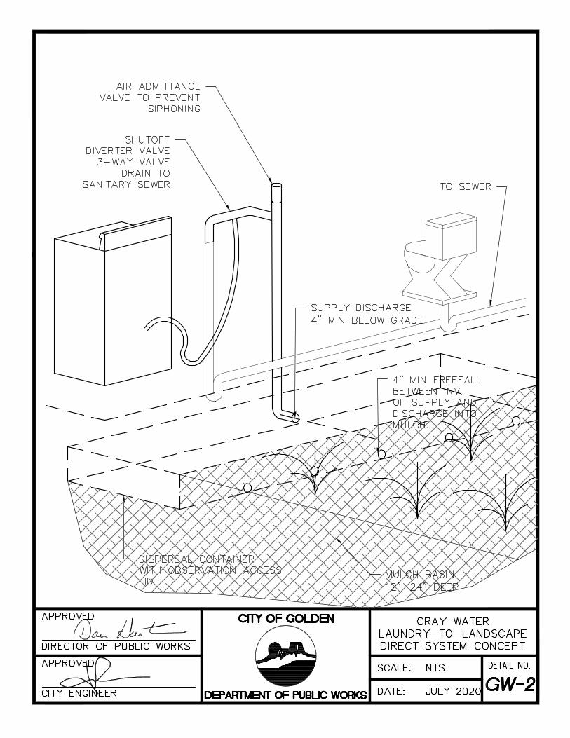
GW-2 Gray Water Laundry-To-Landscape Direct System Concept
Abbreviations and Acronyms
ANSI American Nation Standards Institute
C.R.S. Colorado Revised Statutes
FEMA Federal Emergency Management Agency
Gpd Gallons per Day
GR Granular
IPC International Plumbing Code
Mg/L Milligrams per Liter
MPI Minutes per Inch
NFIP National Flood Insurance Program
NSF NSF International, formally known as National Sanitation Foundation
OWTS On-Site Wastewater Treatment System(s)
PR Prismatic
UIC Underground Injection Control
1.0 Introduction This Design Criteria document contains the minimum requirements for all Graywater Systems installed within the City of Golden, Colorado as established by Ordinance 2143 allowing for laundry-to-landscape graywater systems. This design criteria is a direct reflection of the Ordinance noted (and cited Regulation 86) and does not intend to add further restriction or requirement to the ordinance, but merely consolidate and present the information to guide applicants through the design and permitting process.
All Applicable laws and regulations incorporated by reference cited herein include only
those versions that were in effect as of September 10, 2020 and not later amendments
to the incorporated material.
All materials refenced in this Design Criteria document may be examined online, where
available, or at City of Golden Public Works 1445 10th Street, Golden, CO 80401.
A glossary of terms is included in Section 5.

P a g e 3 | 15
2.0 Design Criteria All graywater systems must be designed to meet the requirements of this Design
Criteria Document, City adopted International Plumbing Codes, the backflow prevention
requirements identified in Section 7 – Part 7 (Backflow Prevention Devices) of Golden’s
Water and Sanitary Sewer Specifications. The following minimum design criteria is
required for all Graywater Systems within the City of Golden:
2.1 Graywater Use Categories
Graywater systems shall be categorized as follows:
A. Category A: Properties upon which a single-family household building or
structure is located, whereby:
1. Graywater is collected from laundry machines only.
2. Outdoor, subsurface irrigation discharging to a mulch basin within
the confines of the legal property boundary only.
3. Design flow is limited to a maximum of 400 gallons per day for all
combined flow.
B. Category B: Properties upon which a Non-Single-Family structure is
located, whereby:
1. Graywater is collected from laundry machines only.
2. Outdoor, subsurface irrigation discharging to a mulch basin within
the confines of the legal property boundary only.
3. Design flow is limited to a maximum of 2000 gallons per day for all
combined flow.
2.2 Flow Projections
Flow to the graywater system must be calculated based on anticipated
flows/discharge from the laundry washing machine(s).
The design flow of each system component or combination of multiple
components must be greater than the calculated peak graywater production if
upstream of the storage tank, or if no storage tank is proposed with the system.
Graywater Systems may not be used as a factor to reduce the design or capacity
of any domestic wastewater system.
2.3 Graywater System Components
Refer to Exhibit GW-1 for a schematic of a typical graywater system.
A. Diversion Valve: The graywater system must have a diversion valve that
directs graywater from laundry discharge to either the graywater system or
a closed sewerage system. The diversion valve must be:
1. Easily operable
2. Clearly labeled

P a g e 4 | 15
3. Constructed of material that is durable, corrosion resistant,
watertight as allowed per section 702 of the International Plumbing
Code as adopted.
4. Designed to accommodate the inlet and outlet of pipes in a secure
and watertight manner.
5. Indirectly connect the bypass line to the closed sewerage system:
6. Installed as described in Section 1302.8 of the International
Plumbing Code as adopted.
B. The graywater system may not have any piping that allows the storage
tank to be bypassed prior to graywater use.
C. Graywater Storage Tank
1. Constructed of durable, non-absorbent, water-tight, and corrosion
resistant materials:
2. Be closed and have access openings for inspection and cleaning.
3. Be vented: For outdoor tanks the storage tank must have a
downturned screen vent. For indoor tanks, the tank must be vented
to the atmosphere outside of the house.
4. Piping: Tank shall have an overflow line with the same or larger
diameter as the influent line, with no shut-off valve, that is trapped
to prevent the escape of gas vapors from the tank, and that is
indirectly connected to the closed sewerage system. Additionally,
tank piping shall include a valved drain line with the same or larger
diameter line as the influent line that is indirectly connected to the
closed sewerage system.
5. Be a minimum of 50 gallons.
6. Be placed on a stable foundation.
7. If placed outdoors, tank shall not be exposed to direct sunlight.
8. Labeling: Tank shall have a permanent label stating: “Caution! Non-
Potable Water. Do Not Drink.”, and shall include the use of a
pictograph in accordance with Figure 1301.3 of the IPC, as shown
below:

P a g e 5 | 15
D. Backup Potable Water: Greywater systems providing subsurface irrigation
are not required to have a backup potable water system to provide potable
irrigation water when graywater is not being produced or is produced in
insufficient quantities. However, if selected, the backup potable water
system connections must be designed to prevent uncontrolled cross
connections between the graywater system and the potable water system.
To meet this requirement, all connections to public or private potable
water supply systems must be protected in accordance with Section 7 –
Part 7 (Backflow Prevention Devices) of Golden’s Water and Sanitary
Sewer Specifications.
1. Inflow Control: backup system shall have means to control inflow
into the system such as a float control valve or other means.
E. Piping: All greywater piping (inlet and outlet etc.) shall be purple in color or
the piping shall be installed with a purple identification tape (banded) or
wrap. Piping shall be labeled with a flow arrow and the words: “CAUTION:
NONPOTABLE WATER – DO NOT DRINK”. Piping above grade shall
also include a pictograph warning in accordance with Figure 1301.3 of the
IPC as previously noted.
F. Pump: Shall have adequate capacity (volumetric pumping rate, and
discharge pressure) to meet desired irrigation rates and elevations within
the receiving mulch bed(s).
G. Controls: Controls must be present to ensure the distribution of graywater
through the irrigation zone. This may include valves, switches, timers, or
other controllers as needed/appropriate.
2.4 Graywater System Site Considerations
A. Floodways/Floodplains: Graywater systems and graywater use is
prohibited within designated 100-year floodway or 100-year floodplain.
B. Collection and distribution piping and appurtenances for all graywater
systems must be located within the confines of the legal property
boundary on which they are located and not within a City right-of-way or
easement, or an adjacent property.

P a g e 6 | 15
2.5 Graywater Design Criteria for Mulch Basin Irrigation Systems
The following minimum Design Criteria are required for mulch basin irrigation
systems for subsurface irrigation. See Exhibit GW-2 for direct laundry to
landscape mulch system with a mulch bed for further information.
A. Mulch basins must be sized using a site evaluation method as follows:
1. Develop a site map showing the location of proposed graywater
system irrigation components and the irrigation area in relation to
physical features of the property requiring setbacks as noted in
Table-1.
Table 1 – System Setback Requirements Minimum Horizontal Distance
Required From Graywater
Storage Tank Mulch Basin
Buildings 5 feet 10 feet
Property Line Adjoining Private Property
10 feet 10 feet
Property Line Adjoining Private Property with Supporting Property Line Survey
1.5 feet 1.5 feet
Streams/Rivers Outside Floodway
Outside Floodway & 100 Year Floodplain
Domestic Potable Service Line 10 feet 10 feet
Public Water Main 10 feet 10 feet
Public Sewer Main 10 feet 10 feet
2. Conduct a soil investigation to determine long-term acceptance
rates of soils in the mulch basin area. Results will be used as basis
of design. The soil investigation must consist of either:
a) A visual or tactile evaluation of soil profile test pit, or
b) A percolation test.
B. Mulch basins shall meet the following soil requirements for siting and
sizing:
1. Table-2 describes soil types and maximum hydraulic loading rates
for typical soils in the Denver area.
2. Subsurface Irrigation Components of the Graywater System must
be installed in suitable soil as defined in Table-2.
3. A minimum of twenty-four inches (24”) of suitable soil must be
present between the subsurface irrigation components and any
restrictive soil layer, bedrock, concrete, or the highest water table.
Restrictive layers are soil types 4, 4A, and 5 in Table-2.
Table 2 – Soil Requirements

P a g e 7 | 15
Soil Type
USDA Soil Texture
USDA Structure-
Shape
USDA Soil
Structure-Grade
Percolation Rate (MPI)
Loading Rate for
Graywater (gal/sq-ft/day)
0 Soil Type 1 with more than 35% Rock (>2mm)
Soil Types 2-5 with more than 50% Rock (>2mm)
-- 0 (Single Grain)
Less than 5 Not suitable without
augmentation
1.0 with augmentation
1 Sand, Loamy Sand -- 0 5-15 Not suitable without
augmentation 1.0 with
augmentation
2 Sandy Loam, Loam, Silt Loam
PR BK GR 2 (Moderate) 3 (Strong)
16-25 0.8
2A Sandy Loam, Loam, Silt Loam
PR BK GR 0 (none)
1 (Weak) Massive
26-40 0.6
3 Sandy Clay Loam, Clay Loam, Silty
Clay Loam
PR BK GR 2, 3 41-60 0.4
3A Sandy Clay Loam, Clay Loam, Silty
Clay Loam
PR BK GR 0
1 Massive 61-75 0.2
4 Sandy Clay, Clay, Silty Clay
PR BK GR 2, 3 76-90 Not suitable
4A Sandy Clay, Clay, Silty Clay
PR BK GR 0
1 Massive 91-120 Not suitable
5 Soil types 2-4A Platy 1, 2, 3 121+ Not Suitable
4. Soil Suitability
a) Type 2, 2A, 3, or 3A undisturbed, native is suitable for mulch
basins with subsurface graywater irrigation systems.
b) Type 0 or 1 soils must be amended as described in Section
2.5.B.5 to improve drainage characteristics to be suitable for
mulch basins.
c) Type 4, 4A, and 5 are not suitable and must be removed and
replaced with soil with suitable drainage characteristics as
noted above.
5. Amended Soils must meet the following criteria to ensure suitable
drainage characteristics for mulch beds.
a) The amendment must have an organic content that is at
least five percent (5%) and no greater than ten percent
(10%).
b) The amendment must be a well-blended mix of mineral
aggregate (soil) and compost where the soil ratio depends
on the requirements for the plant species.

P a g e 8 | 15
c) The mineral aggregate must meet gradation requirements as
set forth in Table-3.
Table 3 – Amendment Soil Gradation
d) Soil amendments must be tilled into the native soil a
minimum of six inches (6”) below the irrigation application
zone.
6. Mulch in beds shall be permeable enough to allow rapid infiltration
of graywater.
C. Irrigation Rates: Irrigation rates must not exceed the allowable soil loading
rates as reflected in Table 2, based on the finest textured soil in the
twenty-four inches (24”) of suitable soil beneath the subsurface irrigation
components.
D. Mulch Basin Geometry
1. Multiple mulch basins may be utilized to meet required volumes/areas.
2. Mulch basin must have a minimum depth of twelve inches (12”)
below grade and not more than twenty-four inches (24”) below
grade.
3. Mulch basins must only be located on slopes of less than thirty
percent (30%) from horizontal.
4. Mulch Basin Minimum Void Space
a) If the graywater system does not have a storage tank, the
basin shall have a minimum void space of three (3) times the
average daily flow for graywater system. This provides
sufficient volume for graywater surges and prevention of
surfacing or runoff.
b) If the graywater system has a storage tank as identified, the
minimum void space is one and a half (1.5) times the
anticipated average daily flow.
E. Mulch Basin Supply Lines:
1. All mulch basin supply lines shall be polyethylene tubing or PVC
Class 200 pipe or better and Schedule 40 fittings. All joints shall be
pressure tested at 40 psi and shown to be drip tight for five minutes
before burial.
2. Mulch basin supply lines must discharge a minimum of four inches
(4”) below grade into a container for dispersal of graywater into the
mulch basin. The container must be designed to have four (4”) of
Sieve Percent Passing
3/8 Inch 100
No. 4 95-100
No. 10 75-90
No. 40 25-40
No. 100 4-10
No. 200 2.5

P a g e 9 | 15
freefall between the invert of the discharge pipe and the mulch. The
container must have an access lid for observation of flow to check
Mulch levels.
2.6 Signage Requirements
A. General Requirements:
1. Words on signs shall be legibly and indelibly printed on a tag or
sign constructed of a corrosion-resistant waterproof material or
shall be indelibly printed on the fixture. The letters of the words
shall be not less than 0.5 inch in height and in colors in contrast to
the background on which they are applied.
B. Signage Requirements
1. Use Category A – Single Family Application: No signage
requirements
2. Use Category B – Non-Single-Family Application: Must comply with
the following requirements.
a) A permanent warning sign must be visible at all fixtures from
which graywater is collected. The signs must state that,
“WATER FROM THIS FIXTURE IS REUSED. CHEMICALS,
EXCRETA, PETROLEUM OILS, AND HAZARDOOUS
MATERIALS MUST NOT BE DISPOSED DOWN THE DRAIN”
b) Any room contain graywater system components must have a
sign noting:” CAUTION GRAYWATER SYSTEM, DO NOT
DRINK, DO NOT CONNECT TO THE POTABLE DRINKING
WATER SYSTEM. NOTICE: CONTACT BUILDING
MANAGEMENT PRIOR TO PEFORMING ANY WORK ON
THIS WATER SYSTEM”
c) Each area being irrigated with Graywater must have a sign that
says: “CAUTION GRAYWATER BEING USED FOR
IRRIGATION. DO NOT DRINK, DO NOT CONNECT TO THE
POTABLE DRINKING WATER SYSTEM”
3.0 Operation and Maintenance Manual All graywater systems must have an Operations and Maintenance (O&M) Manual.
3.1 O&M Manual Requirements
A. Graywater System Description: A description of the system including an
equipment list, the design basis data including but not limited to design
flow rates of each component and service area, a system as-built drawing,
and an overall process description.
B. Maintenance Information: A maintenance plan including but not limited to:
Component maintenance schedule, instructions for component repair,
replacement, or cleaning, replacement component source list, testing and

P a g e 10 | 15
frequency for potable backflow prevention device (as applicable), and
instructions for periodic removal of residuals.
C. Operational ranges for parameters including but not limited to operating
pressure ranges, tank level set points, valve status, pump operation
parameters etc.
D. Step-by-step instructions for starting and shutting down the graywater
system including valve operation, any electrical connections, cleaning
procedures, visual inspection, etc.
E. A guide for visually evaluating the system and any problem scope based
on alarm activations, effluent characteristics, system operation, etc.
F. A guide for graywater control measures in which the graywater treatment
works must be operated.
3.2 Operations
A. The graywater system must be operated and maintained in accordance
with the O&M Manual, including all manufacturer recommended
maintenance activities.
B. The O&M manual must remain with the graywater system throughout the
system’s life and be updated based on any upgrades or modifications that
may be made to the system.
C. The O&M manual must be transferred, upon change of ownership or
occupancy, to the new owner or tenant.
4.0 Permitting, Inspection, and Approval
4.1 Permitting
Prior to construction for use, all graywater systems must be permitted by the City of
Golden. Refer to Attachment A for the Preconstruction Design Submittal Checklist &
Form, which shall be submitted, along with required supporting documentation, to the
City of Golden Public Works at 1445 10th Street.
4.2 Fees
A. Fees for review and inspection of graywater systems shall be based on
the valuation of materials and labor in accordance with the established
building permit fee schedule.
4.3 Inspection
A. Prior to approval for use, all graywater systems must be inspected
verified, and accepted by the City of Golden.

P a g e 11 | 15
5.0 References & Glossary of Terms
5.1 References
All references are available for viewing at City of Golden Public Works, 1445 10th Street.
A. City of Golden Municipal Code
B. City of Golden Engineering Standards
C. Colorado Department of Regulatory Agencies, State Plumbing Board
(2018), Plumbing Rules and Regulations (3 CCR 720-1).
D. Colorado Water Quality Control Act (2015), CRS 25-8-101 et. Seq.
E. Colorado Water Quality Control Commission (2015) Regulation 86,
Graywater Control Regulation (5 CCR 1002-86). Effective December
2015.
F. International Code Council (2018). 2018 International Plumbing Code.
5.2 Glossary of Terms
A. Agronomic Rate: The rate of application of nutrients to plants that is
necessary to satisfy the nutritional requirements of the plants.
B. Closed Sewerage System: Means either a permitted sanitary sewer
service, or a permitted and properly functioning OWTS.
C. Component: Means a subpart of the graywater system, which may include
multiple devices such as pumps, tanks, valves, piping, etc.
D. Cross-Connection: Means any connection that could allow any water,
fluid, or gas such that the water quality could present an unacceptable
health and/or safety risk to the public, to flow from any pipe, plumbing
fixture, or a customer’s water system into the public water system’s
distribution system or any other part of the public water system through
backflow.
E. Design: Means the process of selecting and documenting in writing the
size, calculations, site specific data, location, equipment specification and
configuration of system components that match site characteristics and
facility use.
F. Design Flow: Means the estimated volume of graywater per unit of time for
which a component or graywater system is designed.
G. Dispersed Subsurface Irrigation: Means a subsurface irrigation system
that includes piping, emitters, etc. installed throughout the mulch bed area.
H. Facility: Means any building, structure, or installation, or any combination
thereof that uses graywater subject to the Graywater Use Program, is
located on one or more contiguous or adjacent properties, that are owned
and operated by the same person or legal entity.
I. Floodplain (100-year): Means an area adjacent to a river (clear creek) or
other watercourse which is subject to flooding as the result of the
occurrence of a one hundred (100) year flood, and is so adverse to past,
current, or foreseeable construction or land use as to constitute a

P a g e 12 | 15
significant hazard to public or environmental health and safety or to
property, or is designated by the Federal Emergency Management
Agency (FEMA) or National Flood Insurance Program (NFIP). In absence
of FEMA/NFIP maps, a Professional Engineer shall certify the floodplain
elevations.
J. Floodway: Means the channel of the river or other watercourse and
adjacent land areas that must be reserved in order to discharge the base
flood without cumulatively increasing the water surface elevation more
than one foot or as designate by FEMA/NFIP.
K Graywater: means that portion of wastewater that, before being combined
or treated with other wastewater, is diverted from laundry fixtures for the
purpose of being put to beneficial uses. Graywater does not include the
wastewater from toilets, urinals, kitchen sinks, dishwashers, or non-
laundry utility sinks.
L. Graywater System: Means an arrangement of devices and structures used
to (a) collect graywater from the building or facility laundry and to disperse
this water into irrigation.
M. Graywater Use Program: Means the administrative program implemented
by the Department of Environmental Health and administered by the City
of Golden’s Public Works Department to facilitate and regulate graywater
use within the City of Golden.
N. Mulch: Means organic material including but not limited to leaves,
prunings, straw, and wood chips.
O. Mulch Basin: Means a type of irrigation or treatment field filled with mulch
or other approved permeable material of a sufficient depth, length, and
width to prevent ponding or runoff. A mulch basin may include a basin
around a tree, a trough along a row of plants, or other shapes necessary
for irrigation.
P. Non-Single-Family: Means any structure that is not a single-family
residential structure.
Q. Potable Water System: Means the system for the provision of water to the
public for human consumption through pipes and other constructed
conveyances.
R. Professional Engineer: Means an engineer licensed in accordance with
section 12-25-1, C.R.S.
S. Public Water System: Means a system for the provision of water to the
public for human consumption through pipes or other constructed
conveyances.
T. Single Family: Means a detached or attached structure , arranged and
designed as a single family residential unit intended to be occupied by not
more than one family, and that has separate water and sewer service
connections from other dwelling units.

P a g e 13 | 15
U. Site Evaluation: Means a comprehensive analysis of soil and site
conditions for a graywater irrigation area.
V. Soil Horizon: Means layers in the soil column differentiated by changes in
texture, color, redoximorphic features, bedrock, structure, consistence,
and any other characteristic that affects water movement.
W. Soil Profile Test Pit: Means a trench or other excavation used for access
to evaluate the soil horizons for properties influencing effluent movement,
bedrock, evidence of seasonal high ground water, and other information to
be used in locating and designing a graywater irrigation area.
X. Subsurface Irrigation: Means discharge of graywater into a soil/mulch
area.
Y. Suitable Soil: Means unsaturated soil in which the movement of water, air,
and growth of roots is sustained to support healthy plant life and conserve
moisture.

P a g e 14 | 15
Attachment A – Preconstruction Design Submittal Checklist & Form
Base Information
Owner/Operator Name:
Owner/Operator Signature:
Legal Address of Graywater System:
Owner/Operator Phone:
Owner/Operator Email:
Graywater Use Category A (Single Family) B(Non-Single-Family)
Graywater Design Flow Laundry Machines Daily Flow/Machine
Required Supporting Documents
☐ System Layout Drawing/Schematic – Showing all components and fixtures, pipe
sizes, lengths slopes, equipment locations, mulch pit dimensions/volumes, etc.
The schematic shall also include an operational narrative and an equipment list.
☐ Site Map - Showing the location of proposed graywater system irrigation
components and the mulch pit irrigation area in relation to physical features of
the property and required setbacks as noted in the Design Criteria.
☐ Soil Investigation Summary – Results of the soil profile test pit, percolation test,
and identification of soil type(s), suitability, and loading rates as noted in the
Design Criteria. If applicable shall also denote soil amendments, or replacement
requirements.

P a g e 15 | 15
Attachment B – Post Construction Checklist & Form
Base Information
Owner/Operator Name:
Owner/Operator Signature:
Legal Address of Graywater System:
Owner/Operator Phone:
Owner/Operator Email:
Graywater Use Category A (Single Family) B(Non-Single-Family)
Graywater Design Flow Laundry Machines Daily Flow/Machine
Required Supporting Documents
☐ As-Built System Drawing/Schematic – Showing all components and fixtures, pipe
sizes, lengths slopes, equipment locations, mulch pit dimensions/volumes, etc.
The record drawing shall also include an operational narrative and an equipment
list.
☐ As-Built Site Map – Showing the location of proposed graywater system irrigation
components and the mulch pit irrigation area in relation to physical features of
the property and required setbacks as noted in the Design Criteria.
☐ Operations & Maintenance Manual – As required in the Design Criteria.