Embed Size (px)
Citation preview
CAVITY TRAYS andPREFORMED DPCs
CI/SfB (21.9) Xn6Uniclass L3271
May 2004

CAVITY TRAYS
INTRODUCTION: CAVITY TRAYS & PREFORMED DPCs
Requirements
In cavity walls, dpc design should be based onthe assumption that rain will penetrate the outerleaf of brickwork or blockwork and run down theinside face of the wall. Anything which crossesor obstructs the cavity can form a bridge allowingwater to cross and soak through the inner leaf,causing damp within the building.
For this reason the Building Regulations 1991Approved Document C4 paragraph 4.12 statesthat the cavity of an external wall may be bridged only by wall ties or by damp-proof traysprovided to prevent moisture being carried to theinner leaf.
The Approved Document also refers to BS 5628: Part 3: 1985 and BS 8215: 1991, bothof which require that watertight cavity trays mustbe provided above all points where the cavity isbridged (other than by wall ties), and where anexternal wall becomes an internal wall at a lowerlevel.
These provisions are to ensure that water isdiverted to the outer leaf or clear of the bridges.
Cavity trays are necessary in both double leafmasonry construction and masonry cladding totimber frame construction.
The Building Regulations 1991 ApprovedDocument C4 and BS 5628: Part 3 also requirethe cavity width to be a minimum of 50mm, butwhere there is an increased risk of rainpenetration a wider cavity should be considered.Partial filling of a cavity with insulation batts willnot affect the resistance to wind-driven rainprovided that the remaining cavity is not lessthan 50mm wide.
Problems of conventional trays
Many current failures in building construction can be traced to faulty damp proof coursescaused by:� incorrect choice of materials� inadequate and incorrect detailing� faulty installation.
Many common details required in cavity trayssuch as corners, ends and changes in levelcannot be formed satisfactorily on site fromnormal dpc sheet materials. External corners inparticular are almost impossible to form on sitewithout leaving gaps where water canpenetrate.
Difficult junctions have traditionally been left tothe bricklayer on site to resolve. It may nolonger be sufficient to rely on site expertise, andoften there is little incentive for the bricklayer todo a careful job in forming corners and junctions.
Investigations by the Building ResearchEstablishment have revealed many faults in dpcsincluding:� omission of stop ends� cut pieces butt jointed at corners� joints not properly lapped� trays not properly tucked into the
inner leaf� trays not properly supported� trays not fixed to timber framing.
Once the building is completed, remedial actionto correct these faults is very costly. The expense of taking the trouble to ensure acorrect installation in the first place is negligiblecompared with the cost of putting faults rightafter the building is completed and occupied.

3
CONTENTS
The range
The Z-Led Cavity Tray range has beendeveloped over many years of intensiveresearch and design starting from first principles.By analysing the problems of traditional dampproof course materials and current proprietarypreformed cavity trays, Z-Led can offer the onlyrange of cavity trays which overcomes thedetailing and installation problems of existingproducts.
Z-Led Cavity Trays incorporate features andbenefits across the range to achieve reliabilitythrough ease of installation. � All components are preformed or precreased,
avoiding the need to create complex shapeson site.
� Manufactured from robust polypropylene sheet(unless otherwise stated in productdescriptions), the trays are virtuallyindestructible on site.
� One design is suitable for all masonry andtimber-frame cavity walls.
� Resistant to acids, sulphates and alkalis likelyto come into contact with the trays.
� Integral ribbing or textured finish provides anexcellent mortar key.
� Trays are available with and without factory-fitted lead flashings where applicable.
� A simple range of components for eachapplication makes specifying and orderingvery easy.
Bespoke specials service
Z-Led offer a full range of standard specials suchas chimney trays, arch trays and bullseyes andcan provide quotations within 24 hours. Inaddition a free design service can be providedfor bespoke preformed, moulded or weldedaccessories including pre-creased roll to suitprecise design requirements.
Technical support
Z-Led can provide a comprehensive technicaladvisory service covering product advice andselection, estimation, and dpc design forresidential or larger commercial projectsdesigned to meet all regulatory requirements.Simply forward floor plans, elevation and sectiondrawings and we will prepare a detailedquotation covering all components required.Alternatively contact our Technical Servicesdepartment for assistance.
Quality assurance
The Z-Led Cavity Tray range has beenappraised under BS EN ISO 9001: 2000 whichcover design and development as well asmanufacture, giving an independently auditedand monitored assurance that the products aredesigned to meet their intended purpose.
ABUTMENTS: ROOF/WALL
INTRA WEEP AT ABUTMENT TRAYS page 4
AT BLOCKWORK ABUTMENT TRAYS page 8
TYPICAL APPLICATIONS page 10
WALLS, PARAPETS
HT HORIZONTAL TRAYS page 11
HTR REFURBISHMENT TRAYS page 14
PT PARAPET TRAYS page 16
WINDOW AND DOOR OPENINGS
ST SILL TRAYS page 17
GCC CAVITY CLOSERS AND FORMERS page 18
LT LINTEL TRAYS page 19
ARCHES AND CURVED OPENINGS
AR ARCH FORMERS page 20
BE BULLSEYE WINDOW TRAYS page 20
OTHER APPLICATIONS
PF PREFORMED DPC SYSTEM page 22
ASG ABUTMENT SECRET GUTTER page 25
CT CHIMNEY TRAYS page 26
RADON PROTECTION page 27
REFERENCES
REGULATIONS AND CODES page 28
4
ABUTMENTS: ROOF/WALL
INTRA WEEP AT ABUTMENT TRAYS
Use
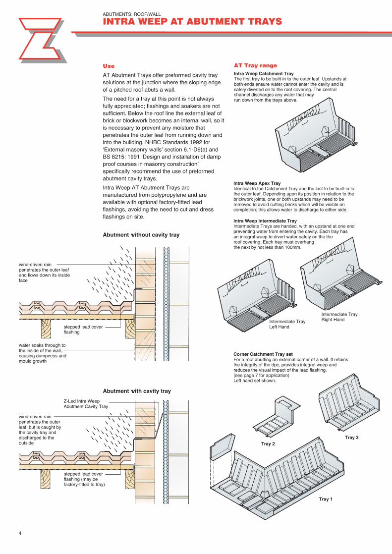
AT Abutment Trays offer preformed cavity traysolutions at the junction where the sloping edgeof a pitched roof abuts a wall.
The need for a tray at this point is not alwaysfully appreciated; flashings and soakers are notsufficient. Below the roof line the external leaf ofbrick or blockwork becomes an internal wall, so itis necessary to prevent any moisture thatpenetrates the outer leaf from running down andinto the building. NHBC Standards 1992 for‘External masonry walls’ section 6.1-D6(a) andBS 8215: 1991 ‘Design and installation of dampproof courses in masonry construction’specifically recommend the use of preformedabutment cavity trays.
Intra Weep AT Abutment Trays aremanufactured from polypropylene and areavailable with optional factory-fitted leadflashings, avoiding the need to cut and dressflashings on site.
AT Tray rangeIntra Weep Catchment TrayThe first tray to be built-in to the outer leaf. Upstands atboth ends ensure water cannot enter the cavity and issafely diverted on to the roof covering. The central channel discharges any water that may run down from the trays above.
stepped lead coverflashing
Abutment without cavity tray
Abutment with cavity tray
wind-driven rainpenetrates the outerleaf, but is caught bythe cavity tray anddischarged to theoutside
Intermediate TrayRight Hand
Intra Weep Apex TrayIdentical to the Catchment Tray and the last to be built-in tothe outer leaf. Depending upon its position in relation to thebrickwork joints, one or both upstands may need to beremoved to avoid cutting bricks which will be visible oncompletion; this allows water to discharge to either side.
Intra Weep Intermediate TrayIntermediate Trays are handed, with an upstand at one endpreventing water from entering the cavity. Each tray has an integral weep to divert water safely on the the roof covering. Each tray must overhang the next by not less than 100mm.
Corner Catchment Tray setFor a roof abutting an external corner of a wall. It retainsthe integrity of the dpc, provides integral weep and reduces the visual impact of the lead flashing.(see page 7 for application)Left hand set shown.
wind-driven rainpenetrates the outer leafand flows down its insideface
water soaks through tothe inside of the wall,causing dampness andmould growth
stepped lead coverflashing (may be factory-fitted to tray)
Z-Led Intra WeepAbutment Cavity Tray
Intermediate TrayLeft Hand
Tray 1
Tray 2Tray 3

5
� Universal designFor 20º to 55º roof pitches (see Table 1 overleaf).
� Integral weepPatented integral weep discharges on to theroof slope to meet the requirement of BS 8215: 1991 that “at least one weepholeis required per cavity tray” for stepped cavitytrays. Avoids the build-up of water flowtowards the bottom of the run, and the riskof leakage if any one unit is badly installed,or if mortar droppings cause blockage.
Advantages
Installation of lead flashing
� Independently certified bythe British Board ofAgrément.
� Comprehensive installationinstructions provided.
AT Trays with lead flashing
Apex Tray
Intermediate Tray left hand
Intermediate Tray right hand
Catchment Tray left hand
Catchment Tray right hand
� Integral pitch marksLocated on the back of eachtray, these help easy and quick installation and avoid incorrect positioning on site.
� 140mm upstandMeets or exceeds therequirements of BS 5628:Part 3: 2001, BS 8215:1991, and NHBCStandards 1992. It is self-supporting, enabling thetrays to be used withcavities of any width from50mm upwards.
� Self-supportingInner and outer leaves of thewall can be built independently,because the tray does notneed to be tied to the innerleaf. This avoids the need tocut blocks horizontally andsaves time.
� Brick backstopsEnsure correct positioning ofbricks, and aid breaking up ofany mortar that may fall intothe cavity tray, assistingdrainage.
� Factory-fitted leadflashing (optional)Trays are also availablewith factory-fitted code 4lead flashings to BS EN12588: 1999 (Code 5available to special order).The flashing, secured byheavy duty stainless steelstaples, together with theweather protection lip andthe bitumen butyl seal,provides completeprotection against weathergiving a driving rainresistant solution in eventhe most exposed sites.When installed the sidelapexceeds the minimum LSArequirement of 50mm.
Removal of tab
Before mortar has set
� Fleximouth mortar barrierActs as a mortar barrier onthe lower leading edge ofthe tray during installation.Once the mortar has set,the protruding tab is pulledand the hinge breaks awayleaving a 25mm deepgroove in accordance withLead Sheet Associationrequirements. This allowsfor a lead flashing to beinstalled without the need torake out the joint, whichcould damage the tray.Patent no 2263288B.
weather protection lip
protruding tabintermittent hinge
mortar barrier 25mm deep groove
lead flashing
bitumen butyl seal
heavy dutyfixing staples

6
ABUTMENTS: ROOF/WALL
INTRA WEEP AT ABUTMENT TRAYS
Typical application: alternative flashings
Flashing fitted after installation oftrays and completion of brickwork
Table 1 Intra Weep AT range and Corner Catchment Tray Set for brickwork
Tray type Length Code For roof(mm) left hand right hand non handed pitches
Without lead flashings Intermediate 305 AT302 AT301 20º - 55º
Catchment/Apex 320 AT300 20º - 55º
Corner Catchment Set CCS LH CCS RH 20º - 37.5º, 40º - 50º
With factory-fitted lead flashings Intermediate 305 AT302* AT301* 20º, 25º, 30º, 35º, 40º, 45º, 50º, 55º **
Catchment 320 AC302* AC301* 20º, 25º, 30º, 35º, 40º, 45º, 50º, 55º **
Apex 320 AT300* 20º - 35º, 40º - 55º
Corner Catchment Set CCS LH* CCS RH* 20º, 25º, 30º, 35º, 40º, 45º, 50º **
*Add /L for long flashing or /S for short flashing. Use long flashings for dressing over profiled tiles. Use short flashings fordressing over the upstand of soakers. For flat interlocking tiles see ASG Abutment Secret Gutter page 25.
**For 2.5º increments use the tray designed for the next higher pitch, eg for a 32.5º roof pitch, use a 35º tray.
Continuous step flashing Single step flashing
Intra Weep intermediate tray(cutting of bricks will be necessaryin most cases, however leadflashings will cover this).
minimum 50mm overlap betweenflashings
Trays with factory-fitted lead.Recommended forexposed locations

7
Typical application: corner abutment
Corner Catchment Tray set: installationPosition trays in successive courses of brickwork
Specification clauses
Intra Weep AT Abutment Traysfor brickwork Provide cavity trays at roof/wallabutments to comply with BS8215: 1991. Trays to be Z-LedIntra Weep AT Abutment Trays,preformed, self-supporting, eachtray with integral weep, and pitchmarks. *Trays without factory-fittedlead flashing: After mortar hasset, remove mortar protectorfrom each tray to leave 25mmdeep groove for lead flashing tocomply with Lead SheetAssociation recommendations.* Trays with factory-fitted leadflashing: Each tray to havefactory-fitted code 4 lead flashingto BS EN 12588: 1999 with butylseal between lead and tray, tosuit roof pitch and covering.
Corner Catchment Tray Set forBrickworkProvide cavity trays at cornerabutment junction to comply withBS 8215: 1991. Trays to be Z-Led Corner Catchment TraySet, preformed and self-supporting with integralbedweep.*Tray Set ref: CCS RH/LH* 20-37.5º/40-50º* (without factory-fitted lead flashing).*Tray Set ref: CCS RH/LH* pitchL/S*, with factory-fitted code 4lead flashing to BS EN 12588:1999, with butyl seal betweenlead and tray, to suit roof pitch.
All traysInstall in accordance withmanufacturer’s instructions.
* delete as appropriate.
AT Tray
Apex TrayOne or both upstands removed toretain brick bond
Corner Catchment Tray set
Tray 1 Tray 2 Tray 3
Intermediate Trays

ABUTMENTS: ROOF/WALL
AT BLOCKWORK ABUTMENT TRAYS
8
Use
AT Trays for abutments to blockwork areavailable in three sizes for different roof pitchesand course heights (see Table 2). Manufacturedfrom polypropylene.
Intermediate Trays are handed. Catchment andApex Trays are identical and suit all roof pitchesfrom 15º to 55º. Due to the size of blockscompared to bricks (typically 225mm courseheight) the trays do not sit directly on top of eachother, and the AT100 Connector Unit is used toweather the vertical face of all blocks betweentrays.
ASG Abutment Secret Gutter(see page 25)
AT Blockwork Tray range
Intermediate Tray right hand
Apex Tray/Catchment Tray
Intermediate Tray left hand
Typical application
AT Blockwork Intermediate Tray withfactory-fitted short leadflashing dressed overgutter upstand
AT100 Connector Unit
225mm
Underlay omitted for clarity
AT100 Connector Unit(cut down for 150mmcourse height)
110mm110mm
polystyrene strip toassist in raking outjoint for site-fittedlead flashing
length according to roof pitch
75mm
102mm
flat interlocking tiles

9
Catchment Tray right hand
Table 2 AT Trays for BlockworkRoof pitch** Course height†
150mm 225mmleft hand right hand left hand right hand
Intermediate Trays (with or without flashing)25º AT602* AT601* AT602* AT601*30º AT402* AT401* AT602* AT601*35º AT402* AT401* AT602* AT601*40º AT302* AT301* AT402* AT401*45º AT302* AT301* AT402* AT401*50º AT302* AT301* AT302* AT301*55º AT302* AT301* AT302* AT301*
Catchment/Apex Trays (without flashing)25º - 30º AT600 (non-handed) AT600 (non-handed) 35º - 50º AT300 (non-handed) AT600 (non-handed)
Catchment Trays (with flashing)25º, 30º AC602* AC601* AC602* AC601*35, 40º, 45º, 50º AC302* AC301* AC602* AC601*
Apex Trays (with flashing)25º - 35º AT600* (non-handed) AT600* (non-handed) 40º - 50º AT300* (non-handed) AT600* (non-handed)
Connector Unit (used with all trays)25º - 50º AT100 (non-handed) AT100 (non-handed)
*Add /L for long flashing or /S for short flashing and /150 or /225 to denote course height.Use long flashings for dressing over profiled tiles. Use short flashings for dressing overthe upstand of soakers.For flat interlocking tiles see ASG Abutment Secret Gutter page 25.**For 2.5º roof pitches, use the tray designed for the next higher pitch, eg for a 32.5º roofpitch use a 35º tray.†For 75mm course heights use Intra Weep Abutment Trays (pages 4-7)
Appearance of flashingDue to the size of blocks the amount of exposedlead may not be aesthetically acceptable. Thiscan be reduced by one of the the followingmethods:
Using brickwork around the cavity traysThe bricks will be hidden by the flashings. In thiscase use Intra Weep AT Abutment Trays (pages 4-7).
Rendering the wallRendering should not be applied directly toflashings as this restricts movement and couldcause splitting of the flashing or detachment ofthe rendering. Fix expanded mesh to theblockwork, extending down to a bellcast stopbead 150mm off the finished roof line, partlycovering the lead; this provides a key for therender and enables the lead to move. The rendering will block the tray dischargechannels, so an MV650 Microvent Weephole issupplied with the Catchment Tray. Ensure this iskept clear of render and mortar.
Random course stoneworkFor random course stone and blockwork, useregular 300mm modular blocks around the cavitytray area in conjunction with Intra WeepAbutment Trays to produce a neat finish.
Trays with factory-fitted lead flashingAT Blockwork Trays are also available withoptional factory-fitted lead flashings, avoiding theneed to cut and dress flashings on site.
Catchment and Apex Trays with factory-fittedlead flashing differ, and the Catchment andIntermediate Trays are handed.
roof underlay
Specification clauses
AT Trays for blockwork(without factory-fitted leadflashing)Provide cavity trays at roof/wallabutments to comply with BS8215: 1991. Trays to be Z-LedAT Blockwork Abutment Trays,preformed and self-supporting.Install in accordance withmanufacturer’s instructions. Afterinstallation remove polystyrenestrip from each tray to leave25mm deep groove for leadflashing to comply with LeadSheet Associationrecommendations.
AT Trays for blockwork (withfactory-fitted lead flashing)Provide cavity trays at roof/wallabutments to comply with BS 8215: 1991. Trays to be Z-Led AT Blockwork AbutmentTrays, preformed and self-supporting, each tray withfactory-fitted code 4 lead flashingto BS EN 12588: 1999 with butylseal between lead and tray, tosuit roof pitch, roof covering andcourse height. Install inaccordance with manufacturer’sinstructions.Apex Tray
Intermediate Trayleft hand
Intermediate Tray right hand
Catchment Tray left hand
Rendering to reduce exposed lead
expanded metal fixed to blockworkextending down to bead, to providekey for rendering
lead visible
150mm
bellcast bead fixed toblockwork forming stopfor rendering

ABUTMENTS: ROOF/WALL
AT ABUTMENT TRAYS
10
Corner abutment
Top side/edge abutment flush intersection
HT5 Horizontal Tray
Bed Weep
AT302 Intra Weep Intermediate Tray left hand
AT300 Intra WeepCatchment Tray
Typical applications

WALLS, PARAPETS
HT HORIZONTAL TRAYS
11
Use
HT Horizontal Trays are used:- at top edge abutments of lower level pitched roofs- where flat roofs abut the outer leaf of a cavity wall- at changes of level where AT Trays are notappropriate, eg on sloping ground- where brickwork is built off a concrete slab orstructural ring beam- at the base of masonry cavity walls- over air bricks, ducting and other services which bridge the cavity.
Advantages� Suitable for brickwork and blockwork.� Self-supporting design allows trays to be used
with cavity widths from 50mm upwards withoutthe need to build-in to the inner leaf.
� Avoids the need to build inner and outerleaves together and to line up bed joints inbrickwork and blockwork leaves.
� The tray lip projects slightly from the wall wheninstalled. This gives a neater appearance thanconventional dpcs and prevents pointing over,a common fault.
� Preformed from polypropylene, internal andexternal angles, step units and stop ends.
� Optional factory-fitted lead flashings removethe need to rake out joints and point inflashings, saving time, cost and additionaltrades.
� Interlocking design ensures overlap of at least100mm as recommended by BS 8215: 1991(Section 6.3 Table 3). Each component has apre-applied bitumen butyl seal at eachoverlap.
� Complies with BS 5628: Part 3: 2001.� Comprehensive installation instructions
provided.� Independently certified by the British Board
of Agrément.
HT Tray range
HT5 Horizontal Tray Supplied in 1125mm lengths (5 brick module). Shorterlengths can be easily cut onsite
HT20 Universal jointing pieceAdjustable lap to allow for siteinaccuracies and non-modular lengths.
HT21 Internal cornerHT22 External cornerOvercome the problem of sitefabrication of difficult junctions.Interlock with HT5 Trays to form acontinuous weatherproof dpc.
HTL75 Left to right step downHTR75 Right to left step downEnable a dpc to be stepped by 75mm(one brick course). For larger stepsuse two or more units in succession,or AT100 Connector Unit for steps ofup to 225mm (see page 8).
HT11 Left hand stop endHT12 Right hand stop endProvide protection to the ends of a trayrun, preventing moisture from enteringthe cavity in compliance with BS 5628:Part 3: 2001 and BS 8215: 1991.
Bed Weep or MV650 Perpend WeepOption of fitting in bed or perpend joint to allow waterto drain from the trays in compliance with BS 5628:Part 3: 2001 and BS 8215: 1991. The Bed Weepmortar protection tab is removed after installation toleave a clean and effective weep hole.
112mm
75mm
112mm
58mm 100mm
mortarprotection tab
275mm275mm
350mm350mm
1125mm
100mm
102mm
245mm
12
WALLS, PARAPETS
HT HORIZONTAL TRAYS
HT Trays with factory-fitted leadflashing
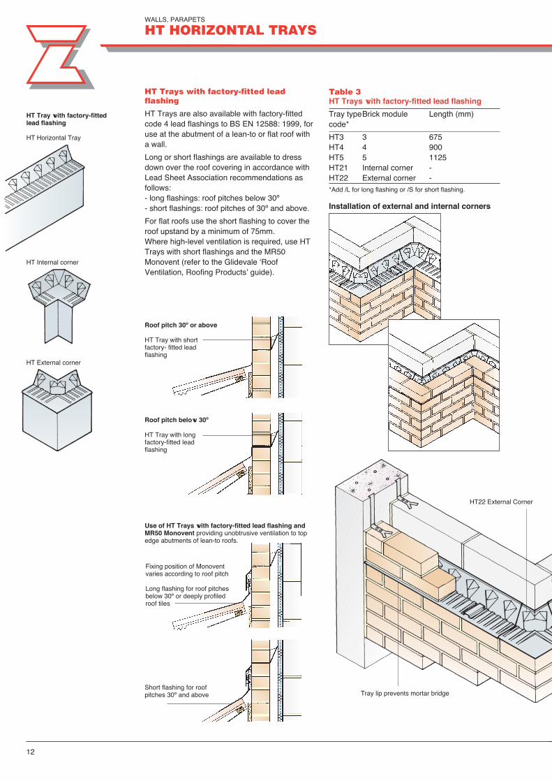
HT Trays are also available with factory-fittedcode 4 lead flashings to BS EN 12588: 1999, foruse at the abutment of a lean-to or flat roof witha wall.
Long or short flashings are available to dressdown over the roof covering in accordance withLead Sheet Association recommendations asfollows:- long flashings: roof pitches below 30º- short flashings: roof pitches of 30º and above.
For flat roofs use the short flashing to cover theroof upstand by a minimum of 75mm.Where high-level ventilation is required, use HTTrays with short flashings and the MR50Monovent (refer to the Glidevale ‘RoofVentilation, Roofing Products’ guide).
Table 3HT Trays with factory-fitted lead flashing
Tray typeBrick module Length (mm)code*
HT3 3 675HT4 4 900HT5 5 1125HT21 Internal corner - HT22 External corner - *Add /L for long flashing or /S for short flashing.
Installation of external and internal corners
Roof pitch 30º or above
HT Tray with short factory- fitted lead flashing
HT Tray with factory-fittedlead flashing
HT Horizontal Tray
HT Internal corner
HT External corner
Roof pitch below 30º
HT Tray with longfactory-fitted leadflashing
Fixing position of Monoventvaries according to roof pitch
Long flashing for roof pitchesbelow 30º or deeply profiledroof tiles
Use of HT Trays with factory-fitted lead flashing andMR50 Monovent providing unobtrusive ventilation to topedge abutments of lean-to roofs.
Short flashing for roofpitches 30º and above
HT22 External Corner
Tray lip prevents mortar bridge

13
Specification clauses
HT Horizontal Trays (withoutfactory-fitted lead flashing)Provide horizontal cavity trays tocomply with BS 8215: 1991.Trays to be Z-Led HT HorizontalTrays, preformed and self-supporting with brick backstops.Install in accordance withmanufacturer’s instructions usingBed Weeps and other HT Trayaccessories, with pre-appliedbitumen butyl seal at eachoverlap.
HT Horizontal Trays (withfactory- fitted lead flashing)Provide horizontal cavity trays tocomply with BS 8215: 1991.Trays to be Z-Led HT HorizontalTrays, preformed and self-supporting with brick backstops.Code 4 lead flashings factory-fitted to each tray with butyl sealbetween lead and tray, to suitroof pitch. Install in accordancewith manufacturer’s instructionsusing Bed Weeps and other HTTray accessories, with pre-applied bitumen butyl seal ateach overlap.
Typical applications
Meter box bridging the cavity HT Horizontal Tray
Bed Weep
Structural ring beam
Bed weep supplied separately
HT21 Internal Corner
HT Horizontal Tray

14
Use
HTR Refurbishment Trays are used forrefurbishment work and repairs to failed cavitytrays. HTR Trays are particularly useful wherean extension with a lean-to or flat roof is builtagainst an existing cavity wall.
Advantages
� Each 560mm unit has a back channel whichcarries water to the central discharge channel,removing the need for weepholes.
� The 21⁄2 brick length is designed for ease ofsequential installation.
� The self-supporting design allow the trays tobe used with cavities of varying width from50mm upwards without the need to build-in tothe inner leaf.
� The tray lip projects slightly from the wall wheninstalled. This gives a neater appearance thanconventional dpc materials and avoids beingpointed over, a common fault which can forma bridge for damp.
� Complies with BS 5628: Part 3: 2001.
� Comprehensive installation instructionsprovided.
� Independently certified by the British Board ofAgrément.
HTR Trays with factory-fitted flashing
HTR Trays are also available with factory- fittedcode 4 lead flashings to BS EN 12588: 1999, foruse at the abutment of a lean-to or flat roof witha wall. These remove the need to rake out jointsand subsequently point in flashings, saving time,cost and the need for additional trades.Long or short flashings are available to dressdown over the roof covering in accordance withLead Sheet Association recommendations asfollows:- long flashings: roof pitches below 30º- short flashings: roof pitches of 30º and above. For flat roofs use the short flashing to cover theroof upstand by a minimum of 75mm. Wherehigh-level ventilation is required, use HTR Trayswith short flashings and the MR50 Monovent.
HTR11 Left hand stop endHTR12 Right hand stop endProvide protection to the ends of atray run, preventing moisture fromentering the cavity in compliancewith BS 5628: Part 3: 1985 and BS 8215: 1991.
HTR Tray with factory-fittedlead flashing
HTR Refurbishment Tray
560mm
central discharge channel
100mm
102mm275mm 275mm
350mm 350mm
112mm
WALLS, PARAPETS
HTR REFURBISHMENT TRAYS
HTR22 External corner
HTR21 Internal corner

15
Installation method
Cut out three bricks.
Fit an HTR11/12 stop endto an HTR Tray unit andinstall on a bed of mortarat the start of the run.
Specification clauses
HTR Refurbishment Trays(without integral lead flashing)Provide horizontal trays tocomply with BS 8215: 1991.Trays to be Z-Led HTRRefurbishment Trays, preformedand self-supporting with integralweep and brick backstops. Installin accordance with manufacturer’sinstructions using wherenecessary HTR accessories,with pre-applied bitumen butylseal at each overlap.
HTR Refurbishment Trays(with integral lead flashing)Provide horizontal trays tocomply with BS 8215: 1991.Trays to be Z-Led HTRRefurbishment Trays, preformedand self-supporting with integralweep and brick backstops. Code4 lead flashings factory-fitted toeach tray with butyl seal betweenlead and tray, to suit roof pitch.Install in accordance withmanufacturer’s instructions usingwhere necessary HTRaccessories, with pre-appliedbitumen butyl seal at eachoverlap
Continue along the wall inthe same way.
Fit another HTR11/12 stopend at the end of the run.
Install the next HTR Trayunit on a mortar bed,overlapping the first trayby 100mm and sealing thejoint with self- adhesivetape.
Replace two bricks,wedged and bedded onmortar, then cut out thenext two bricks.

WALLS, PARAPETS
PT PARAPET TRAYS
16
Use
PT Parapet Trays, manufactured from pre-creased polypropylene, are used for parapetwalls to flat and pitched roofs where both brickskins are exposed to weather. BS 5628: Part 3: 1985 and BS 8215: 1991recommend a cavity tray stepped down at least150mm. There is no recommendation as towhich way the tray should step down. If stepped inwards, moisture could travel alongthe underside of the tray and into the building;however, this is only likely in very exposedsituations. If stepped outwards, the tray willdirect water to the outer face of the wall whichmay cause staining.
Advantages� Can be installed to direct water inwards or
outwards as required.
� Complies with BS 5628: Part 3: 1985 and BS 8215: 1991.
� Comprehensive installation instructionsprovided.
� Formed from continuous roll to reduce joints and overlaps.
PT10 Parapet Tray
PT Parapet Tray range
Capawal GRP Canopy System
Specification clause
PT Parapet TraysProvide parapet trays to complywith BS 8215: 1991. Trays to bepreformed Parapet Trays tied toboth inner and outer leaves,preformed and self- supportingwith brick backstops. Install inaccordance with manufacturer’sinstructions using Bed Weepsand other PT Tray accessories,with pre-applied bitumen butylseal at each overlap.
PT Tray directing water outwards
PT Tray directing water inwards
PT12 Stop End(right hand)Prevents moisturefrom entering thecavity at the ends ofPT10 tray runs. PT11Stop End for lefthand applications.
100mm
225 or 150mm
100mm50, 75 or100mm 100mm
100mm
100mm
100mm
225 or150mm
50, 75 or100mm
Bed Weep or MV650 Perpend WeepOption of fitting in bed or perpend joint to allow waterto drain from the trays in compliance with BS 5628:Part 3: 2001 and BS 8215: 1991. Gives a neaterappearance than an open perpend. The Bed Weepmortar protection tab is removed after installation toleave a clean and effective weep hole.
Tape2mm x 12mm Bitumen ButylJointing Tape
100mm58mm
PT22 Universal Corner 90ºReversible as shown forinternal or external corners,and to discharge outwardsor inwards.
WINDOW AND DOOR OPENINGS
ST SILL TRAYS
17
ST Sill Trays
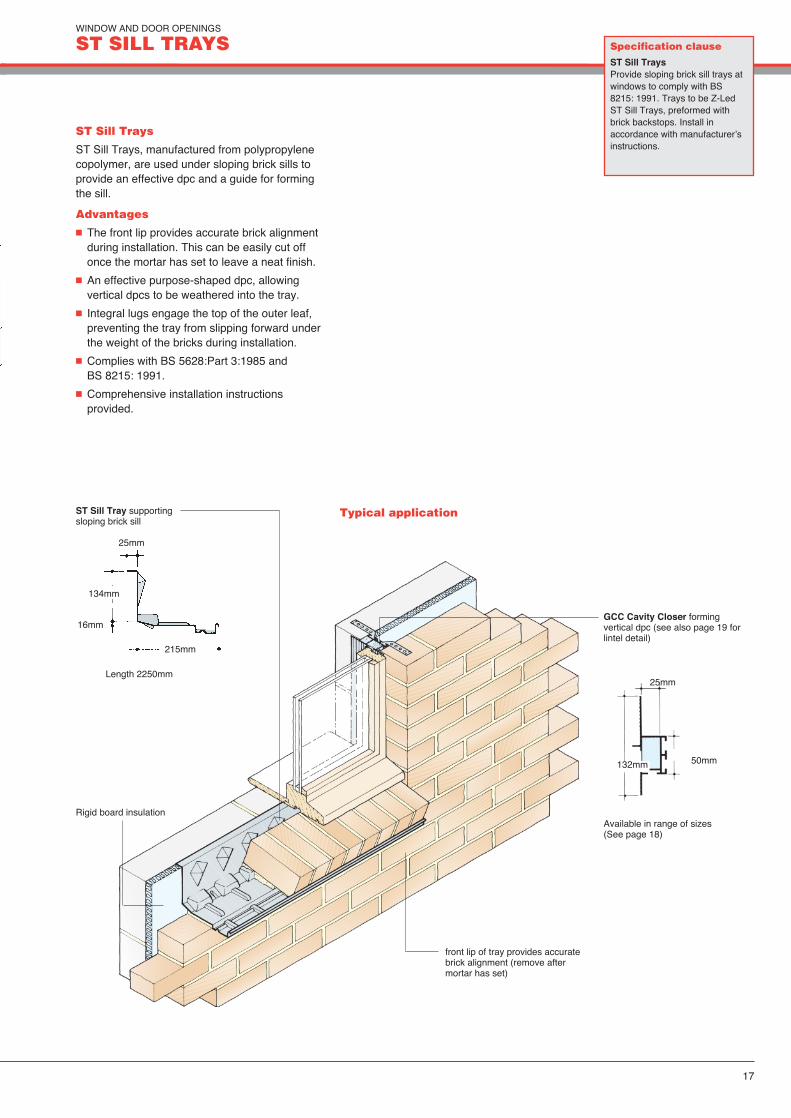
ST Sill Trays, manufactured from polypropylenecopolymer, are used under sloping brick sills toprovide an effective dpc and a guide for formingthe sill.
Advantages
� The front lip provides accurate brick alignmentduring installation. This can be easily cut offonce the mortar has set to leave a neat finish.
� An effective purpose-shaped dpc, allowingvertical dpcs to be weathered into the tray.
� Integral lugs engage the top of the outer leaf,preventing the tray from slipping forward underthe weight of the bricks during installation.
� Complies with BS 5628:Part 3:1985 and BS 8215: 1991.
� Comprehensive installation instructionsprovided.
Specification clause
ST Sill TraysProvide sloping brick sill trays atwindows to comply with BS8215: 1991. Trays to be Z-LedST Sill Trays, preformed withbrick backstops. Install inaccordance with manufacturer’sinstructions.
Typical applicationST Sill Tray supportingsloping brick sill
Length 2250mm
25mm
134mm
215mm
16mm
front lip of tray provides accuratebrick alignment (remove aftermortar has set)
GCC Cavity Closer formingvertical dpc (see also page 19 forlintel detail)
Rigid board insulationAvailable in range of sizes(See page 18)
50mm
25mm
132mm

WINDOW AND DOOR OPENINGS
GCC CAVITY CLOSERS & ZFF 2000 FRAME FORMERS
18
GCC Cavity Closers
Use
GCC is a rigid PVCu cavity closer which is filledwith closed cell, CFC-free insulation.
The GCC system conforms to the requirementsoutlined in Building Regulations Part L referringto conservation of fuel and power.
In addition Z-Led GCC, when installed aroundwindow and door apertures, can prevent thepassage of moisture into the inner leaf of thecavity, so complying with Part C of BuildingRegulations.
Advantages � Complies with Building Regulations Part.� Eliminates cold bridging at windows and door
reveals� Suitable for cavities between 50 - 100mm� Provides damp proof barrier between inner
and outer walls at point of closure� For use with timber, PVCu or metal window
and door frames
Specification clause
GCC Cavity ClosersProvide cavity closers at jambsand sills of all window and dooropenings. Closers to bepreformed PVC-U GlidevaleCavity Closers to suit cavitywidth and have integral framestops, expanded polystyreneinsulation and capillary bars.Install cavity closers inaccordance with manufacturer’sinstructions, with Glidevale GAT4Anchor Ties in pairs every225mm on jambs to secure theclosers in position.
Window frame
GCC Cavity Closer
Fastening tie
ZFF 2000 Frame Formers
Use
ZFF 2000 insulated cavity closers can be factoryassembled as three or four-sided frame formers tosuit cavity widths from 50mm to 130mm.
They can be used with all window types to acceptsnap-in or second fix frames and provideimmediate closure of the cavity. This gives thebenefit of accurate, mechanically jointed frameformers, factory-made to fit specific brick openingsizes and eliminating the need for site-fabricatedtemplates.
The time saving and speed of constructionbenefits when using sub-frames are significant,with formers supplied flat-packed for easyassembly on site, or pre-assembled.
Advantages � Insulated cavity closer, dpc and frame former
in one� Second fix or snap-in for all window types� Delivered to site flat-packed or pre-assembled� Saves time on site� Can also be supplied with 30 minutes fire
integrity (mineral wool insulation).
Pre-formed window unit
ZF 2000 Frame former tosuit cavities 50-130mm

WINDOW AND DOOR OPENINGS
LT LINTEL TRAYS
19
Use
LT Lintel Trays, manufactured frompolypropylene copolymer, are used with steellintels over openings. Steel lintels are sometimesclaimed to act as cavity trays, but they lack stopends, so there is a risk of water leakage at theends unless they are extended well beyond thelength needed for structural purposes. BS 5628:Part 3: 2001 and BS 8215: 1991 recommend theuse of cavity trays with stop ends over allopenings. There is also a risk of corrosion of thelintel if the protective coating is scratched duringbricklaying.
LT Lintel Trays with LTU Stop Ends solve allthese problems. As steel lintels should last atleast 60 years, they are a small price to pay foradded protection.For concrete or stone lintels it is normallypossible to use HT Horizontal Trays with stop ends.
Advantages
� Suitable for brickwork and blockwork.
� Self-supporting design can be used withcavities from 50mm to 100mm withoutbuilding-in to inner leaf.
� Stop Ends supplied separately can bepositioned to fit brick perpends.
� Complies with BS 5628: Part 3: 1985.
� Non-slip textured finish for improved mortaradhesion.
� Supplied by the metre to a maximum of 60mper roll, accommodates 1, 2 or 3 brick courseheights.
� Suits most common types of steel lintelincluding Catnic, IG, BAT, Dorman Long,Birtley, Rom, Hilsmith and Asset BuildingComponents.
Typical application
Specification clause
LT Lintel TraysProvide lintel trays at allopenings to comply with BS8215: 1991. Trays to beGlidevale LT Lintel Trays,preformed and self-supporting.Install with Bed Weeps and LTULintel Tray Stop Ends with pre-applied bitumen butyl seal, inaccordance with manufacturer’sinstructions.
LT Tray bedded on flange ofsteel lintel (not tied in to innerleaf)
tray rises minimum 150mmacross cavity (BS 5628: Part 3)
Bed Weep
GCC Cavity Closer formsvertical dpc
bricks bedded on mortaron LT Tray
LTU Stop End

ARCHES AND CURVED OPENINGS
AR ARCH TRAY & BE BULLSEYE WINDOW TRAY
20
Use
Z-Led arch formers and trays provide fullyeffective dpc protection to cavity walls abovearched and curved openings.
Self-supporting designs do not need tying in tothe inner leaf. LTU Stop Ends and Bed Weepssupplied separately (see page 18).
Conventional dpcs cannot be easily sitefabricated into a suitable shape for archprotection. The common practice of providing ahorizontal dpc across the crown of the archleaves the arch masonry and adjacent brickworkunprotected against water penetration.
AR Arch Tray
Provides full dpc protection to archesconstructed with temporary formwork.
Advantages
� Enables traditional formwork constructionmethods.
� Design does not require tying in to the innerleaf of masonry.
� Purpose-made to rise, radius and shaperequired.
� Manufactured from durable polyproylene.
Typical applications
AR Arch Tray
Bed Weep
LTU Stop EndBE Bullseye Window Tray
Preformed 360º tray providing full dpc protectionaround a circular or bullseye window.
Advantages
� Purpose-made to window size.
� Positively drains to the outside.
� Two-piece design assists installation.
� Manufactured from durable polyproylene.

21
Specification clauses
AR Arch TraysProvide dpcs to brick/blockarches over openings usingpreformed purpose-made Z-LedAR Arch Trays with Stop Endsand Bed Weeps. Install inaccordance with manufacturer’sinstructions.
BE Bullseye Window TraysProvide dpcs to brick/blockcircular (bullseye) windows usingpreformed purpose-made Z-LedBE Bullseye Window Trays withStop Ends and Bed Weeps.Install in accordance withmanufacturer’s instructions.
BE Bullseye Window Tray
Bed Weep
LTU Stop End

OTHER APPLICATIONS
PF PREFORMED DPC SYSTEM
22
Use
The Z-Led Preformed DPC system has beendeveloped for use in larger commercial projectswhere there may be many repetitive or complexdpc design details.The system comprisespreformed straight runs and moulded or weldedaccessories, all purpose-made in polypropylenecopolymer to match exactly the constructionaldetailing.
Advantages
� Bespoke products reduce wastage on site andensure a faster installation than traditionalmethods.
� Preformed moulded or welded accessoriesremove the need for site fabrication and aremore reliable.
� Dpc widths and other dimensions tailored toeach application and detail.
� Proven bitumen butyl jointing system.
� Dpcs do not require support across the cavity.
� Non-slip textured finish for improved mortaradhesion.
� Complies with BS 5628: Part 3: 2001 and BS 8215: 1991.
� Factory-fitted lead flashings to BS EN 12588: 1999 available where required, in a range of weights.
Preformed DPC sectionsCommonly used preformed dpc sections;other shapes can be made to order.

23
Accessories
Commonly used preformed accessories areshown. Others can be made to order.
Units are designed for building-in to both leavesof a cavity wall: either brick-brick or brick-block.
Surface-fixed units are built-in to the outer leafand rest against the face of the inner leaf,column etc.
Internal/external cornerbrick/block-brick
Internal cornersurface-fixed
Change of levelbrick/block-brick (right hand shown)
External cornersurface-fixed
Change of levelsurface-fixed (right hand shown)
Column stop endsurface-fixed (right hand shown)
Column stop endbrick/block-brick (right hand shown)
Stop endsurface-fixed (right hand shown)
Stop endbrick/block-brick (right hand shown)
Beam/column stop endbrick/block-brick (right hand shown)
LTU Stop End (see page 19)
Bed Weep (see page 16)
100mm
150mm
50, 75 or100mm
100mm
100mm
100mm225 or 150mm
50, 75 or100mm
100mm
100mm 100mm
150mm
100mm
50, 75 or 100mm
100mm
225 or 150mm
50, 75 or100mm
100mm
100mm 100mm
75 or 225mm 50, 75 or100mm
100mm
100mm
100mm 100mm
75 or 225mm
150mm
150 or 225mm
100mm
100mm 100mm50, 75 or100mm
60mm
100mm
100mm
100mm
150 or 225mm
150 or 175mm
100mm
150mm
100mm100mm
60mm
50, 75 or100mm
50, 75 or100mm
100mm
100mm
225 or 150mm
100mm
100mm
100mm 100mm
150mm

24
OTHER APPLICATIONS
PF PREFORMED DPC SYSTEM
Typical applications
Window sills
GCC Cavity Closer
PF preformed cavitytray unit
tray continues beyond window reveal with preformed stop end
Bed Weep
Bed Weep
PF preformed dpc to fit around column
Column at intermediateconcrete floor

OTHER APPLICATIONS
ASG ABUTMENT SECRET GUTTER
25
Use
The ASG Abutment Secret Gutter is for usewhere the sloping edge of a flat interlocking tiledroof abuts a wall. With flat tiles, there is a risk ofwater penetration by capillary action betweenthe lead or other oversoakers and the tiles,particularly on exposed sites or at low roofpitches. Because of this BS 8000: Part 6: 1990recommends the use of a secret gutter in theseconditions.
Care is required in the design of secret gutters;a 40mm gap is recommended between the faceof the abutment wall and the tile edge to allowfor cleaning out leaves and debris.
The ASG Abutment Secret Gutter should beused in conjunction with Z-Led Intra WeepAbutment Trays with factory-fitted lead flashings.
In sheltered situations use trays with shortflashings.
In exposed situations, use trays with longflashings secured by clips to act as a coverflashing.
Advantages� Preformed shape and light weight enable
quick and easy installation.� Reduces the risk of theft from site as the
product is of no value to thieves.� Positive 25mm upstand obviates the need for
capillary weather bars which cause adjacent tiles to kick up.
� Complies with recommendations of BS 8000: Part 6: 1990.
� Designed in accordance with Lead SheetAssociation dimensional requirements.
� Resistant to UV light degradation.� Fire rating: designated AB to BS 476:
Part 3.� Pultruded GRP with additional surface gel coat� Comprehensive installation instructions
provided.
ASG Abutment Secret Gutter
Specification clause
ASG Abutment Secret GutterProvide abutment secret guttersto comply with BS 8000: Part 6:1990. Gutters to be preformed Z-Led ASG Abutment SecretGutters with AB fire rating to BS 476: Part 3 . Install in accordance withmanufacturer’s instructions.
Typical applications
Sheltered situations
Intra Weep AT Tray with factory-fitted short lead flashingdressed over gutter upstand
ASG Abutment Secret Gutter
3000mm
flat interlocking tiles
roof underlay50 x 50mm timbersupport
100 x 50mm rafter
100 x 50mm rafter
Exposed situations
Intra Weep AT Tray withfactory-fitted long lead flashingdressed over tiles
150mm minimum
50 x 50mm timbersupport
flat interlocking tiles
roof underlay
25mm
40mm
125mm
75mm

26
OTHER APPLICATIONS
CT CHIMNEY TRAYS
CTHL Chimney Tray, High Level
Required to prevent the entry of water athigh level where a chimney rises througha pitched roof; suitable for new-build orremedial work. Minimises disturbance tosurrounding construction in remedialwork.
Material: Lead sheet to BS 1178: 1982‘Specification for milled lead sheet forbuilding purposes’. Code 4 as standard,code 5 to special order.
Standard sizes: 800 x 800mm, 900 x900mm, 950 x 950mm.
To suit either 195mm square or 195mmdiameter circular flue.Other sizes to special order.
Upstand to be cut on siteand folded down overflashing
CTLL Chimney Tray, Low Level
Required at low level where a cavity-walledchimney with brick shoulders is built on to anexternal wall; the tray prevents water whichmay enter the shoulders from penetrating tothe inner leaf of the wall.
Material: 1mm aluminium alloy sheet to BS EN 485-2: 1995 ‘Aluminium and aluminium alloys. Sheet strip and plate.Mechanical properties’. This has a higher melting point than lead, so is suitable for installation close to a heat source.
Standard size: to suit 1115 x 510mm chimney. Other sizes to special order.
Note: lead or aluminium sheet builtinto brickwork or concrete as adamp proof course should beprotected with a thick coat ofbitumen paint before installation.
CT Chimney Trays
CT chimney trays protect against waterpenetration at high or low level.
� Comply with Building Regulations and NHBCStandards, which require the use of metaltrays in chimneys.
� Preformed components help to achieve a highstandard of appearance.
Flashings by others
� Eliminate the need for labour in forming unitson site.
� One-piece welded designs for speed ofinstallation.
� Maintain protection whilst accommodatingnormal site inaccuracies.

27
OTHER APPLICATIONS
RADON PROTECTION
RS22 Slab Edge BarrierUniversal Corner(external or internal)
RSE Radon Slab Edge Barrier
RPS1 Universal Pipe SealSeals around service pipeswhich penetrate the radonmembrane. Fits pipe/sleevediameters of 100 to 120mm.
RAC RadonAirbrick CloakProvides continuitywhere the cavity barriermeets a subfloor airbrick/vent
A comprehensive range of pre-formed accessoryproducts is also available to protect againstradon penetration at cavities, corners, pipe andservice entries, etc.
� Provides both radon protection and dampproofing.
� Universal size fits cavities from 50 to 100mm.Also suits 150mm deep suspended floors.Specials can be made to suit otherapplications.
� Ribbed surface of Radon Cavity Barrierpromotes mortar adhesion and prevents thecreation of slip planes in masonry.
� Universal Slab Edge Barrier in 2.25 metrelengths designed to accommodate slabthicknesses of 100 or 150mm.
� Unique slab settlement joint allows forsettlements of concrete slab without affectingthe integrity of the radon barrier.
� Pre-formed Slab Edge Universal Corners arereversible for either internal or externalcorners and are available to suit both 100mm(R22/100) or 150 (RS22/150) slab thickness.
� Underfloor vents should be installed inaccordance with Building RegulationsApproved Document C, equivalent to1500mm2 ventilation area per metre ofperimeter wall. Site not more than 2m apart,around the whole perimeter if possible toavoid stagnant air pockets.
Typical applications
RSE Radon Slab Edge Barrier
All joints lapped and sealedwith double-sided Butyl Tape
Bedweep
Maxi-Vent& Maxi-SleevePeriscope
Radon Shield
RT10 RadonCavityBarrier
MV650
Z-Led HT5HorizontalCavityTray RAC Radon Airbrick Cloak
RSE Radon Slab Edge Barrier
Radon/damp proof membrane
Replacement air to radonsump via voids in fill material
Rad
on g
asR
ainw
ater
RT10 RadonCavity Barrier
RS Radon Sump
RT22 Cavity BarrierUniversal Corner(external or internal)
Radon Shield MembraneProtect Radon Shield 375 is a strong durablemembrane, green in colour, manufactured from a low and medium density polyethylene copolymer.
� Quick and easy to install� Can also be used as a damp proof membrane

CAVITY TRAYS AND PREFORMED DPC’s
REFERENCES
Z-LED LimitedUnit 9, Tonbridge Chambers, Pembury Road,
Tonbridge, Kent TN9 2HZTelephone 01732 363443
Fax 01732 363553Email [email protected] Web site www.z-led.com
We reserve the right to amend product specifications without notice.
Technical supportZ-LED offer a full technical advisory andestimating service. Simply forward floor plans,elevation and section drawings and we willprepare a detailed quotation covering allcomponents required. Deliveries are packagedand labelled by plot to ease identification, andare phased to suit your building programme. P
rodu
ced
by T
ed H
astin
gs/R
ackl
ey D
esig
n
Regulations and codes
The Z-Led Cavity Tray range can be used tocomply with the requirements of buildingregulations, codes of practice and standards asfollows:
England and WalesThe Building Regulations 2000 ApprovedDocument C4 ‘Resistance to weather andground moisture’ (1992 edition).
ScotlandThe Building Standards (Scotland) Regulations1991, Technical Standards for Compliance G3.1‘Resistance to precipitation’.
Northern IrelandThe Building Regulations (Northern Ireland)1994 C ‘Site preparation and resistance tomoisture’.
Republic of IrelandBuilding Regulations 1991 C4 ‘Resistance toweather and ground moisture’.
BS 5628: Part 3: 2001 ‘Code of practice for useof masonry’.
BS 8215: 1991 ‘Design and installation of dampproof courses in masonry construction’.
BS EN 12588: 1999 ‘Specification for milled leadsheet for building purposes’.
BS 8000: Part 3: 1990 ‘Code of practice for useof masonry (workmanship on building sites)’.
National House Building Council (NHBC)Standards (UK and N Ireland).
National House Building Guarantee Scheme(NHBGS) Standards (Republic of Ireland).
BBA Certificate no 89/2187 covers the followingproducts:
Intra Weep Abutment Trays AT 300 series, AT 400 series.
HT Horizontal Trays
Refurbishment Trays HTR.