Embed Size (px)
Citation preview

Americas HeadquartersCisco Systems, Inc.170 West Tasman DriveSan Jose, CA 95134-1706 USAhttp://www.cisco.comTel: 408 526-4000
800 553-NETS (6387)Fax: 408 527-0883
Cisco Unified IP Conference Station 7937G Administration Guide for Cisco Unified Communications Manager 6.0
Text Part Number: OL-11560-01 Rev. B0 1725-40072-001 Rev. A1

THE SPECIFICATIONS AND INFORMATION REGARDING THE PRODUCTS IN THIS MANUAL ARE SUBJECT TO CHANGE WITHOUT NOTICE. ALL STATEMENTS, INFORMATION, AND RECOMMENDATIONS IN THIS MANUAL ARE BELIEVED TO BE ACCURATE BUT ARE PRESENTED WITHOUT WARRANTY OF ANY KIND, EXPRESS OR IMPLIED. USERS MUST TAKE FULL RESPONSIBILITY FOR THEIR APPLICATION OF ANY PRODUCTS.
THE SOFTWARE LICENSE AND LIMITED WARRANTY FOR THE ACCOMPANYING PRODUCT ARE SET FORTH IN THE INFORMATION PACKET THAT SHIPPED WITH THE PRODUCT AND ARE INCORPORATED HEREIN BY THIS REFERENCE. IF YOU ARE UNABLE TO LOCATE THE SOFTWARE LICENSE OR LIMITED WARRANTY, CONTACT YOUR CISCO REPRESENTATIVE FOR A COPY.
The following information is for FCC compliance of Class A devices: This equipment has been tested and found to comply with the limits for a Class A digital device, pursuant to part 15 of the FCC rules. These limits are designed to provide reasonable protection against harmful interference when the equipment is operated in a commercial environment. This equipment generates, uses, and can radiate radio-frequency energy and, if not installed and used in accordance with the instruction manual, may cause harmful interference to radio communications. Operation of this equipment in a residential area is likely to cause harmful interference, in which case users will be required to correct the interference at their own expense.
The following information is for FCC compliance of Class B devices: The equipment described in this manual generates and may radiate radio-frequency energy. If it is not installed in accordance with Cisco’s installation instructions, it may cause interference with radio and television reception. This equipment has been tested and found to comply with the limits for a Class B digital device in accordance with the specifications in part 15 of the FCC rules. These specifications are designed to provide reasonable protection against such interference in a residential installation. However, there is no guarantee that interference will not occur in a particular installation.
Modifying the equipment without Cisco’s written authorization may result in the equipment no longer complying with FCC requirements for Class A or Class B digital devices. In that event, your right to use the equipment may be limited by FCC regulations, and you may be required to correct any interference to radio or television communications at your own expense.
You can determine whether your equipment is causing interference by turning it off. If the interference stops, it was probably caused by the Cisco equipment or one of its peripheral devices. If the equipment causes interference to radio or television reception, try to correct the interference by using one or more of the following measures:
• Turn the television or radio antenna until the interference stops.
• Move the equipment to one side or the other of the television or radio.
• Move the equipment farther away from the television or radio.
• Plug the equipment into an outlet that is on a different circuit from the television or radio. (That is, make certain the equipment and the television or radio are on circuits controlled by different circuit breakers or fuses.)
Modifications to this product not authorized by Cisco Systems, Inc. could void the FCC approval and negate your authority to operate the product.
The Cisco implementation of TCP header compression is an adaptation of a program developed by the University of California, Berkeley (UCB) as part of UCB’s public domain version of the UNIX operating system. All rights reserved. Copyright © 1981, Regents of the University of California.
NOTWITHSTANDING ANY OTHER WARRANTY HEREIN, ALL DOCUMENT FILES AND SOFTWARE OF THESE SUPPLIERS ARE PROVIDED “AS IS” WITH ALL FAULTS. CISCO AND THE ABOVE-NAMED SUPPLIERS DISCLAIM ALL WARRANTIES, EXPRESSED OR IMPLIED, INCLUDING, WITHOUT LIMITATION, THOSE OF MERCHANTABILITY, FITNESS FOR A PARTICULAR PURPOSE AND NONINFRINGEMENT OR ARISING FROM A COURSE OF DEALING, USAGE, OR TRADE PRACTICE.
IN NO EVENT SHALL CISCO OR ITS SUPPLIERS BE LIABLE FOR ANY INDIRECT, SPECIAL, CONSEQUENTIAL, OR INCIDENTAL DAMAGES, INCLUDING, WITHOUT LIMITATION, LOST PROFITS OR LOSS OR DAMAGE TO DATA ARISING OUT OF THE USE OR INABILITY TO USE THIS MANUAL, EVEN IF CISCO OR ITS SUPPLIERS HAVE BEEN ADVISED OF THE POSSIBILITY OF SUCH DAMAGES.CCVP, the Cisco logo, and the Cisco Square Bridge logo are trademarks of Cisco Systems, Inc.; Changing the Way We Work, Live, Play, and Learn is a service mark of Cisco Systems, Inc.; and Access Registrar, Aironet, BPX, Catalyst, CCDA, CCDP, CCIE, CCIP, CCNA, CCNP, CCSP, Cisco, the Cisco Certified Internetwork Expert logo, Cisco IOS, Cisco Press, Cisco Systems, Cisco Systems Capital, the Cisco Systems logo, Cisco Unity, Enterprise/Solver, EtherChannel, EtherFast, EtherSwitch, Fast Step, Follow Me Browsing, FormShare, GigaDrive, HomeLink, Internet Quotient, IOS, iPhone, IP/TV, iQ Expertise, the iQ logo, iQ Net Readiness Scorecard, iQuick Study, LightStream, Linksys, MeetingPlace, MGX, Networking Academy, Network Registrar, PIX, ProConnect, ScriptShare, SMARTnet, StackWise, The Fastest Way to Increase Your Internet Quotient, and TransPath are registered trademarks of Cisco Systems, Inc. and/or its affiliates in the United States and certain other countries.
All other trademarks mentioned in this document or Website are the property of their respective owners. The use of the word partner does not imply a partnership relationship between Cisco and any other company. (0708R)
Any Internet Protocol (IP) addresses used in this document are not intended to be actual addresses. Any examples, command display output, and figures included in the document are shown for illustrative purposes only. Any use of actual IP addresses in illustrative content is unintentional and coincidental.
Cisco Unified IP Conference Station 7937G Administration Guide for Cisco Unified Communications Manager 6.0 © 2008 Cisco Systems, Inc. All rights reserved.
The Java logo is a trademark or registered trademark of Sun Microsystems, Inc. in the U.S. or other countries.
Cisco Unified IP Conference StaOL-11560-01 Rev. B0
C O N T E N T S
Preface ix
Overview ix
Audience ix
Organization ix
Related Documentation x
Obtaining Documentation, Obtaining Support, and Security Guidelines xi
Cisco Product Security Overview xi
Document Conventions xi
C H A P T E R 1 An Overview of the Conference Station 1-1
Understanding the Conference Station 1-2
What Networking Protocols Are Used? 1-4
What Features are Supported on the Conference Station? 1-5
Feature Overview 1-5
Configuring Telephony Features 1-6
Configuring Network Parameters Using the Conference Station 1-6
Providing Users with Feature Information 1-7
Understanding Security Features for Conference Stations 1-7
Overview of Supported Security Features 1-8
Understanding Security Profiles 1-9
Overview of Configuring and Installing Conference Stations 1-9
Configuring Conference Stations in Cisco Unified Communications Manager 1-9
Checklist for Configuring the Conference Station in Cisco Unified Communications Manager 1-10
Installing Conference Stations 1-12
Checklist for Installing the Conference Station 1-12
C H A P T E R 2 Preparing to Install the Conference Station on Your Network 2-1
Understanding Interactions with Other Cisco Unified IP Communications Products 2-1
Understanding How the Conference Station Interacts with Cisco Unified Communications Manager 2-2
iiition 7937G Administration Guide for Cisco Unified Communications Manager 6.0

Contents
Providing Power to the Conference Station 2-2
Power Guidelines 2-3
Conference Station Power Consumption and Display Brightness 2-3
Power Outage 2-4
Obtaining Additional Information about Power 2-4
Understanding Conference Station Configuration Files 2-4
Understanding the Conference Station Startup Process 2-5
Adding Conference Stations to the Cisco Unified Communications Manager Database 2-7
Adding Conference Stations with Auto-Registration 2-7
Adding Conference Stations with Auto-Registration and TAPS 2-8
Adding Conference Stations with Cisco Unified Communications Manager Administration 2-9
Adding Conference Stations with BAT 2-9
Determining the MAC Address of a Conference Station 2-9
C H A P T E R 3 Setting Up the Conference Station 3-1
Before You Begin 3-1
Network Requirements 3-1
Cisco Unified Communications Manager Configuration 3-2
Safety 3-2
Understanding the Conference Station Components 3-3
Network Ports 3-3
Audio Auxiliary Port 3-4
Installing the Conference Station 3-4
Securing the Conference Station with a Cable Lock 3-7
Verifying the Conference Station Startup Process 3-8
Configuring Startup Network Settings 3-9
Guidelines for Best Performance 3-9
Conference Room Setup Examples 3-10
C H A P T E R 4 Configuring Settings on the Conference Station 4-1
Configuration Menus on the Conference Station 4-1
Displaying a Configuration Menu 4-2
Unlocking and Locking Options 4-3
Editing Values 4-3
Overview of Options Configurable from a Conference Station 4-4
Network Configuration Menu 4-5
ivCisco Unified IP Conference Station 7937G Administration Guide for Cisco Unified Communications Manager 6.0
OL-11560-01 Rev. B0

Contents
Device Configuration Menu 4-8
CallManager Configuration Menu 4-9
HTTP Configuration Menu 4-10
Locale Configuration Menu 4-11
Security Configuration Menu 4-11
QoS Configuration Menu 4-12
Security Configuration Menu 4-12
802.1X Authentication and Status 4-13
C H A P T E R 5 Configuring Features, Templates, Services, and Users 5-1
Telephony Features Available for the Conference Station 5-1
Configuring Corporate and Personal Directories 5-6
Configuring Corporate Directories 5-6
Configuring Personal Directory 5-7
Modifying Button Templates 5-7
Configuring Softkey Templates 5-8
Setting Up Services 5-8
Adding Users to Cisco Unified Communications Manager 5-9
Managing the User Options Web Pages 5-9
Giving Users Access to the User Options Web Pages 5-9
Specifying Options that Appear on the User Options Web Pages 5-9
C H A P T E R 6 Customizing the Conference Station 6-1
Customizing and Modifying Configuration Files 6-1
Creating Custom Conference Station Rings 6-2
Ringlist.xml File Format Requirements 6-2
PCM File Requirements for Custom Ring Types 6-3
Configuring a Custom Conference Station Ring 6-3
Configuring the Idle Display 6-4
C H A P T E R 7 Viewing Model Information, Status, and Statistics on the Conference Station 7-1
Model Information Screen 7-1
Status Menu 7-2
Network Statistics Screen 7-2
Call Statistics Screen 7-4
Device Information Screen 7-5
vCisco Unified IP Conference Station 7937G Administration Guide for Cisco Unified Communications Manager 6.0
OL-11560-01 Rev. B0
Contents
C H A P T E R 8 Monitoring the Conference Station Remotely 8-1
Accessing the Web Page for a Conference Station 8-2
Disabling and Enabling Web Page Access 8-2
Device Information 8-3
Network Configuration 8-4
Ethernet Information 8-6
Device Logging 8-8
Streaming Statistics 8-8
C H A P T E R 9 Troubleshooting and Maintenance 9-1
Viewing Call, Device, and Network Information 9-1
Using Ping 9-2
Resolving Startup Problems 9-2
Symptom: The Conference Station Does Not Go Through its Normal Startup Process 9-3
Symptom: The Conference Station Does Not Register with Cisco Unified Communications Manager 9-3
Checking Network Connectivity 9-4
Verifying TFTP Server Settings 9-4
Verifying IP Addressing and Routing 9-4
Verifying DNS Settings 9-4
Verifying Cisco Unified Communications Manager Settings 9-5
Cisco Unified Communications Manager and TFTP Services Are Not Running 9-5
Creating a New Configuration File 9-5
Registering the Conference Station with Cisco Unified Communications Manager 9-6
Symptom: Conference Station Unable to Obtain IP Address 9-6
Conference Station Resets Unexpectedly 9-7
Verifying Physical Connection 9-7
Identifying Intermittent Network Outages 9-7
Verifying DHCP Settings 9-7
Checking Static IP Address Settings 9-8
Verifying Voice VLAN Configuration 9-8
Eliminating DNS or Other Connectivity Errors 9-8
Checking Power Connection 9-9
General Troubleshooting Tips 9-9
Resetting or Restoring the Conference Station 9-11
Performing a Basic Reset 9-11
Performing a Factory Reset 9-12
Using the Quality Report Tool 9-13
viCisco Unified IP Conference Station 7937G Administration Guide for Cisco Unified Communications Manager 6.0
OL-11560-01 Rev. B0
Contents
Monitoring the Voice Quality of Calls 9-13
Resolving Conference Call Reception Problems 9-14
Where to Go for More Troubleshooting Information 9-15
Cleaning the Conference Station 9-15
A P P E N D I X A Providing Information to Users Via a Website A-1
How Users Obtain Support for the Conference Station A-1
How Users Get Copies of Conference Station Manuals A-1
How Users Subscribe to Services and Configure Conference Station Features A-2
How Users Access a Voice Messaging System A-2
How Users Configure Personal Directory Entries A-3
Installing and Configuring the Cisco Unified Communications Manager Address Book Synchronizer A-3
A P P E N D I X B Supporting International Users B-1
Adding Language Overlays to Conference Station Buttons B-1
Installing the Cisco Unified Communications Locale Installer B-1
A P P E N D I X C Technical Specifications C-1
Physical and Operating Environment Specifications C-1
Cable Specifications C-2
I N D E X
viiCisco Unified IP Conference Station 7937G Administration Guide for Cisco Unified Communications Manager 6.0
OL-11560-01 Rev. B0

Contents
viiiCisco Unified IP Conference Station 7937G Administration Guide for Cisco Unified Communications Manager 6.0
OL-11560-01 Rev. B0
Preface
OverviewThe Cisco Unified IP Conference Station 7937G Administration Guide for Cisco Unified Communications Manager 6.0 provides the information you need to understand, install, configure, manage, and troubleshoot the Cisco Unified IP Conference Station 7937G on a Voice-over-IP (VoIP) network.
Because of the complexity of a Unified Communications network, this guide does not provide complete and detailed information for procedures that you need to perform in Cisco Unified Communications Manager 6.0 or other network devices. See the “Related Documentation” section on page x for a list of related documentation.
AudienceNetwork engineers, system administrators, or telecom engineers should review this guide to learn the steps required to properly set up the conference station on the network.
The tasks described are administration-level tasks and are not intended for end-users of the conference stations. Many of the tasks involve configuring network settings and affect the conference station’s ability to function in the network.
Because of the close interaction between the conference station and Cisco Unified Communications Manager, many of the tasks in this manual require familiarity with Cisco Unified Communications Manager.
OrganizationThis manual is organized as follows:
Chapter Description
Chapter 1, “An Overview of the Conference Station”
Provides a conceptual overview and description of the conference station
Chapter 2, “Preparing to Install the Conference Station on Your Network”
Describes how to install the conference station, and provides an overview of the tasks required prior to installation
ixCisco Unified IP Conference Station 7937G Administration Guide for Cisco Unified Communications Manager 6.0
OL-11560-01 Rev. B0
PrefaceRelated Documentation
Related DocumentationFor more information about the conference station or Cisco Unified Communications Manager, refer to the following publications:
Cisco Unified IP Conference Station 7937G
These publications are available at the following URL:
http://www.cisco.com/en/US/products/hw/phones/ps379/tsd_products_support_series_home.html
• Cisco Unified IP Conference Station 7937G Phone Guide for Cisco Unified Communications Manager 6.0
• Cisco Unified IP Conference Station 7937G Installation Guide
• Regulatory Compliance and Safety Information for the Cisco Unified IP Conference Station 7937G
Cisco Unified Communications Manager
Cisco Unified Communications Manager documents are available at the following URLs:
http://www.cisco.com/en/US/products/sw/voicesw/ps556/tsd_products_support_series_home.html
http://www.cisco.com/en/US/products/ps7273/tsd_products_support_series_home.html
Troubleshooting
This document is available to registered Cisco.com users at the following URL:
http://www.cisco.com/warp/customer/788/AVVID/telecaster_trouble.html
• Using the 79xx Status Information For Troubleshooting tech note
Chapter 3, “Setting Up the Conference Station” Describes how to properly and safely install and configure the conference station on your network
Chapter 4, “Configuring Settings on the Conference Station”
Describes how to configure network, device, and security settings on the conference station
Chapter 5, “Configuring Features, Templates, Services, and Users”
Provides an overview of procedures for configuring telephony features, configuring directories, configuring conference station button and softkey templates, setting up services, and adding users to Cisco Unified Communications Manager
Chapter 6, “Customizing the Conference Station” Explains how to customize configuration files, ring sounds, and the idle display for the conference station
Chapter 7, “Viewing Model Information, Status, and Statistics on the Conference Station”
Explains how to view model, device, and network information from the conference station
Chapter 8, “Monitoring the Conference Station Remotely”
Describes the information that you can obtain from the conference station’s web page
Chapter 9, “Troubleshooting and Maintenance” Provides tips for troubleshooting the conference station
Appendix A, “Providing Information to Users Via a Website”
Provides suggestions for setting up a website for providing users with important information about their conference stations
Appendix B, “Supporting International Users” Provides information about setting up conference stations in non-English environments
Appendix C, “Technical Specifications” Provides technical specifications for the conference station
Chapter Description
xCisco Unified IP Conference Station 7937G Administration Guide for Cisco Unified Communications Manager 6.0
OL-11560-01 Rev. B0
PrefaceObtaining Documentation, Obtaining Support, and Security Guidelines
Obtaining Documentation, Obtaining Support, and Security Guidelines
For information on obtaining documentation, obtaining support, providing documentation feedback, security guidelines, and also recommended aliases and general Cisco documents, see the monthly What’s New in Cisco Product Documentation, which lists all new and revised Cisco technical documentation, at:
http://www.cisco.com/en/US/docs/general/whatsnew/whatsnew.html
Cisco Product Security OverviewThis product contains cryptographic features and is subject to United States and local country laws governing import, export, transfer and use. Delivery of Cisco cryptographic products does not imply third-party authority to import, export, distribute or use encryption. Importers, exporters, distributors and users are responsible for compliance with U.S. and local country laws. By using this product you agree to comply with applicable laws and regulations. If you are unable to comply with U.S. and local laws, return this product immediately. A summary of U.S. laws governing Cisco cryptographic products may be found at: http://www.cisco.com/wwl/export/crypto/tool/stqrg.html. If you require further assistance please contact us by sending E-mail to [email protected].
Document ConventionsThis document uses the following conventions:
Convention Description
boldface font Commands and keywords are in boldface.
italic font Arguments for which you supply values are in italics.
[ ] Elements in square brackets are optional.
{ x | y | z } Alternative keywords are grouped in braces and separated by vertical bars.
[ x | y | z ] Optional alternative keywords are grouped in brackets and separated by vertical bars.
string A nonquoted set of characters. Do not use quotation marks around the string or the string will include the quotation marks.
screen font Terminal sessions and information the system displays are in screen font.
boldface screen font Information you must enter is in boldface screen font.
italic screen font Arguments for which you supply values are in italic screen font.
^ The symbol ^ represents the key labeled Control—for example, the key combination ^D in a screen display means hold down the Control key while you press the D key.
< > Nonprinting characters, such as passwords are in angle brackets.
xiCisco Unified IP Conference Station 7937G Administration Guide for Cisco Unified Communications Manager 6.0
OL-11560-01 Rev. B0
PrefaceDocument Conventions
Note Means reader take note. Notes contain helpful suggestions or references to material not covered in the publication.
Caution Means reader be careful. In this situation, you might do something that could result in equipment damage or loss of data.
Warning This warning symbol means danger. You are in a situation that could cause bodily injury. Before you work on any equipment, be aware of the hazards involved with electrical circuitry and be familiar with standard practices for preventing accidents.
xiiCisco Unified IP Conference Station 7937G Administration Guide for Cisco Unified Communications Manager 6.0
OL-11560-01 Rev. B0
Cisco Unified IP Conference Station 7937G Administration GuOL-11560-01 Rev. B0
C H A P T E R 1
An Overview of the Conference StationThe Cisco Unified IP Conference Station 7937G is a full-featured teleconference station that provides voice communication over an Internet Protocol (IP) network. It functions much like a digital business phone, allowing you to place and receive calls and to access features such as mute, hold, transfer, speed dial, call forward, and more. In addition, because conference stations are connected to your data network, they offer enhanced IP telephony features, including access to network information and services, and customizable features and services. The conference stations also support certain security features.
The conference station provides a backlit LCD screen, support for up to ten speed dial numbers, and a variety of other sophisticated functions.
The conference station, like other network devices, must be configured and managed. The conference stations encode G.711a, G.711u, G.729a, G.729ab, and decode all variants of G.711 and G.729. The conference stations also support 16-bit/16-kHz wideband audio.
This chapter includes the following topics:
• Understanding the Conference Station, page 1-2
• What Networking Protocols Are Used?, page 1-4
• What Features are Supported on the Conference Station?, page 1-5
• Understanding Security Features for Conference Stations, page 1-7
• Overview of Configuring and Installing Conference Stations, page 1-9
Caution Using a cell, mobile, or GSM phone, or two-way radio in close proximity to a Cisco Unified IP Conference Station 7937G might cause interference. For more information, refer to the manufacturer’s documentation of the interfering device.
1-1ide for Cisco Unified Communications Manager 6.0
Chapter 1 An Overview of the Conference StationUnderstanding the Conference Station
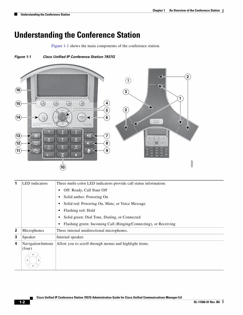
Understanding the Conference Station Figure 1-1 shows the main components of the conference station.
Figure 1-1 Cisco Unified IP Conference Station 7937G
1 LED indicators Three multi-color LED indicators provide call status information:
• Off: Ready, Call State Off
• Solid amber: Powering On
• Solid red: Powering On, Mute, or Voice Message
• Flashing red: Hold
• Solid green: Dial Tone, Dialing, or Connected
• Flashing green: Incoming Call (Ringing/Connecting), or Receiving
2 Microphones Three internal unidirectional microphones.
3 Speaker Internal speaker.
4 Navigation buttons (four)
Allow you to scroll through menus and highlight items.
10
9
8
7
6
5
4
2
3
2
1
16
15
14
13
12
11
1
1852
61
1-2Cisco Unified IP Conference Station 7937G Administration Guide for Cisco Unified Communications Manager 6.0
OL-11560-01 Rev. B0

Chapter 1 An Overview of the Conference StationUnderstanding the Conference Station
5 Select button Activates the currently highlighted screen menu option.
6 On-hook button Ends your current call.
7 Volume Up button Raises the volume of the speaker (off-hook) and the volume of the ringer (on-hook).
8 Volume Down button
Lowers the volume of the speaker (off-hook) and the volume of the ringer (on-hook).
9 Mute button Toggles the Mute feature.
10 Keypad Allows you to dial conference station conference station numbers, enter letters, and choose menu items.
11 Redial button Dials the most recent number you called.
12 Directories button Toggles the Directories menu. Allows you to access call logs, speed dials, and directories.
13 Applications button
Toggles the Applications menu. Allows you to access the Messages, Settings, and Services menus.
14 Off-hook button Obtains a dial tone to initiate a call, or answers an incoming call.
15 Softkey buttons (four)
Allow you to select softkey options displayed on the screen.
16 Conference station screen
Displays conference station menus and features.
1-3Cisco Unified IP Conference Station 7937G Administration Guide for Cisco Unified Communications Manager 6.0
OL-11560-01 Rev. B0
Chapter 1 An Overview of the Conference StationWhat Networking Protocols Are Used?
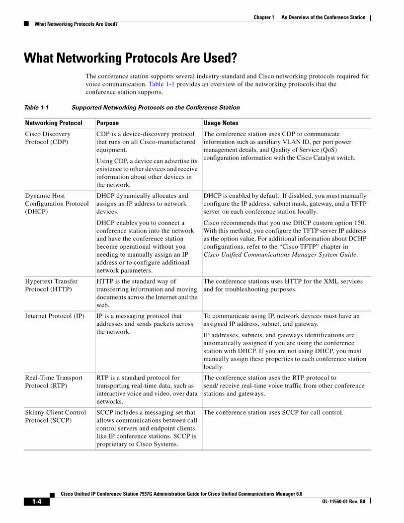
What Networking Protocols Are Used?The conference station supports several industry-standard and Cisco networking protocols required for voice communication. Table 1-1 provides an overview of the networking protocols that the conference station supports.
Table 1-1 Supported Networking Protocols on the Conference Station
Networking Protocol Purpose Usage Notes
Cisco Discovery Protocol (CDP)
CDP is a device-discovery protocol that runs on all Cisco-manufactured equipment.
Using CDP, a device can advertise its existence to other devices and receive information about other devices in the network.
The conference station uses CDP to communicate information such as auxiliary VLAN ID, per port power management details, and Quality of Service (QoS) configuration information with the Cisco Catalyst switch.
Dynamic Host Configuration Protocol (DHCP)
DHCP dynamically allocates and assigns an IP address to network devices.
DHCP enables you to connect a conference station into the network and have the conference station become operational without you needing to manually assign an IP address or to configure additional network parameters.
DHCP is enabled by default. If disabled, you must manually configure the IP address, subnet mask, gateway, and a TFTP server on each conference station locally.
Cisco recommends that you use DHCP custom option 150. With this method, you configure the TFTP server IP address as the option value. For additional information about DCHP configurations, refer to the “Cisco TFTP” chapter in Cisco Unified Communications Manager System Guide.
Hypertext Transfer Protocol (HTTP)
HTTP is the standard way of transferring information and moving documents across the Internet and the web.
The conference stations uses HTTP for the XML services and for troubleshooting purposes.
Internet Protocol (IP) IP is a messaging protocol that addresses and sends packets across the network.
To communicate using IP, network devices must have an assigned IP address, subnet, and gateway.
IP addresses, subnets, and gateways identifications are automatically assigned if you are using the conference station with DHCP. If you are not using DHCP, you must manually assign these properties to each conference station locally.
Real-Time Transport Protocol (RTP)
RTP is a standard protocol for transporting real-time data, such as interactive voice and video, over data networks.
The conference station uses the RTP protocol to send/ receive real-time voice traffic from other conference stations and gateways.
Skinny Client Control Protocol (SCCP)
SCCP includes a messaging set that allows communications between call control servers and endpoint clients like IP conference stations. SCCP is proprietary to Cisco Systems.
The conference station uses SCCP for call control.
1-4Cisco Unified IP Conference Station 7937G Administration Guide for Cisco Unified Communications Manager 6.0
OL-11560-01 Rev. B0

Chapter 1 An Overview of the Conference StationWhat Features are Supported on the Conference Station?
Related Topics
• Understanding Interactions with Other Cisco Unified IP Communications Products, page 2-1
• Understanding the Conference Station Startup Process, page 2-5
• Network Configuration Menu, page 4-5
What Features are Supported on the Conference Station?The conference station functions much like a digital business conference station, allowing you to place and receive teleconference station calls. In addition to traditional telephony features, the conference station includes features that enable you to administer and monitor the conference station as a network device.
This section includes the following topics:
• Feature Overview, page 1-5
• Configuring Telephony Features, page 1-6
• Configuring Network Parameters Using the Conference Station, page 1-6
• Providing Users with Feature Information, page 1-7
Feature OverviewConference stations provide traditional telephony functionality, such as call forwarding and transferring, redialing, speed dialing, conference calling, and voice messaging system access. Conference stations also provide a variety of other features. For an overview of the telephony features that the conference station supports, see the “Telephony Features Available for the Conference Station” section on page 5-1.
As with other network devices, you must configure conference stations to prepare them to access Cisco Unified Communications Manager and the rest of the IP network. By using DHCP, you have fewer settings to configure on a conference station, but if your network requires it, you can manually configure an IP address, TFTP server, and subnet mask. For instructions on configuring the network settings on the conference station, see Chapter 4, “Configuring Settings on the Conference Station.”
Transmission Control Protocol (TCP)
TCP is a connection-oriented transport protocol.
The conference station uses TCP to connect to Cisco Unified Communications Manager and to access XML services.
Trivial File Transfer Protocol (TFTP)
TFTP allows you to transfer files over the network.
On the conference station, TFTP enables you to obtain a configuration file specific to the conference station type.
TFTP requires a TFTP server in your network, which can be automatically identified from the DHCP server. If you want a conference station to use a TFTP server other than the one specified by the DHCP server, you must manually assign a TFTP server from the Network Configuration menu on the conference station.
User Datagram Protocol (UDP)
UDP is a connectionless messaging protocol for delivery of data packets.
The conference station transmits and receives RTP streams, which utilize UDP.
Table 1-1 Supported Networking Protocols on the Conference Station (continued)
Networking Protocol Purpose Usage Notes
1-5Cisco Unified IP Conference Station 7937G Administration Guide for Cisco Unified Communications Manager 6.0
OL-11560-01 Rev. B0
Chapter 1 An Overview of the Conference StationWhat Features are Supported on the Conference Station?
The conference station can interact with other services and devices on your IP network to provide enhanced functionality. For example, you can use XML to enable users to access information such as weather, stocks, quote of the day, and other web-based information. For information about configuring such services, see the “Configuring Corporate and Personal Directories” section on page 5-6 and the “Setting Up Services” section on page 5-8.
Finally, because the conference station is a network device, you can obtain detailed status information from it directly. This information can assist you with troubleshooting any problems users might encounter when using their conference stations. See Chapter 7, “Viewing Model Information, Status, and Statistics on the Conference Station,” for more information.
Related Topics
• Chapter 4, “Configuring Settings on the Conference Station”
• Chapter 5, “Configuring Features, Templates, Services, and Users”
• Chapter 9, “Troubleshooting and Maintenance”
Configuring Telephony FeaturesYou can modify certain settings for the conference station from Cisco Unified Communications Manager Administration. Use this web-based application to set up conference station registration criteria and calling search spaces, to configure corporate directories and services, and to modify conference station button templates, among other tasks. See the “Telephony Features Available for the Conference Station” section on page 5-1 and Cisco Unified Communications Manager Administration Guide for additional information.
For more information about Cisco Unified Communications Manager Administration, refer to Cisco Unified Communications Manager documentation, including Cisco Unified Communications Manager System Guide. You can also use the context-sensitive help available within the application for guidance.
You can access the complete Cisco Unified Communications Manager documentation suite at these URLS:
http://www.cisco.com/en/US/products/sw/voicesw/ps556/tsd_products_support_series_home.html
http://www.cisco.com/en/US/products/ps7273/tsd_products_support_series_home.html
Related Topic
• Telephony Features Available for the Conference Station, page 5-1
Configuring Network Parameters Using the Conference Station You can configure parameters such as DHCP, TFTP, and IP settings on the conference station itself. You can also obtain statistics about a current call or firmware versions on the conference station.
For more information about configuring features and viewing statistics from the conference station, see Chapter 4, “Configuring Settings on the Conference Station,” and Chapter 7, “Viewing Model Information, Status, and Statistics on the Conference Station.”
1-6Cisco Unified IP Conference Station 7937G Administration Guide for Cisco Unified Communications Manager 6.0
OL-11560-01 Rev. B0
Chapter 1 An Overview of the Conference StationUnderstanding Security Features for Conference Stations
Providing Users with Feature InformationIf you are a system administrator, you are likely the primary source of information for conference station users in your network or company. To ensure that you distribute the most current feature and procedural information, familiarize yourself with conference station documentation. Make sure to visit the Cisco Unified IP Conference Station web site:
http://www.cisco.com/en/US/products/hw/phones/ps379/tsd_products_support_series_home.html
From this site, you can access various user guides.
In addition to providing users with documentation, it is important to inform them about available conference station features—including features specific to your company or network—and about how to access and customize those features, if appropriate.
For a summary of some of the key information that conference station users need their system administrators to provide, see Appendix A, “Providing Information to Users Via a Website.”
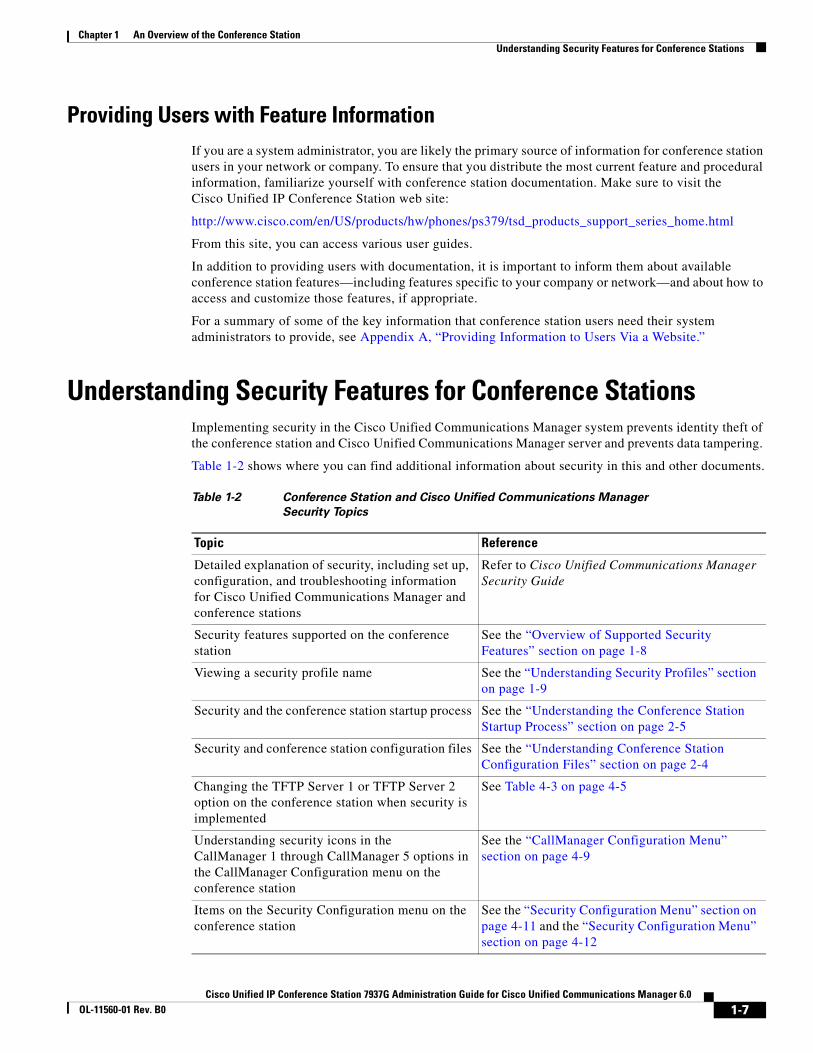
Understanding Security Features for Conference Stations Implementing security in the Cisco Unified Communications Manager system prevents identity theft of the conference station and Cisco Unified Communications Manager server and prevents data tampering.
Table 1-2 shows where you can find additional information about security in this and other documents.
Table 1-2 Conference Station and Cisco Unified Communications Manager Security Topics
Topic Reference
Detailed explanation of security, including set up, configuration, and troubleshooting information for Cisco Unified Communications Manager and conference stations
Refer to Cisco Unified Communications Manager Security Guide
Security features supported on the conference station
See the “Overview of Supported Security Features” section on page 1-8
Viewing a security profile name See the “Understanding Security Profiles” section on page 1-9
Security and the conference station startup process See the “Understanding the Conference Station Startup Process” section on page 2-5
Security and conference station configuration files See the “Understanding Conference Station Configuration Files” section on page 2-4
Changing the TFTP Server 1 or TFTP Server 2 option on the conference station when security is implemented
See Table 4-3 on page 4-5
Understanding security icons in the CallManager 1 through CallManager 5 options in the CallManager Configuration menu on the conference station
See the “CallManager Configuration Menu” section on page 4-9
Items on the Security Configuration menu on the conference station
See the “Security Configuration Menu” section on page 4-11 and the “Security Configuration Menu” section on page 4-12
1-7Cisco Unified IP Conference Station 7937G Administration Guide for Cisco Unified Communications Manager 6.0
OL-11560-01 Rev. B0
Chapter 1 An Overview of the Conference StationUnderstanding Security Features for Conference Stations
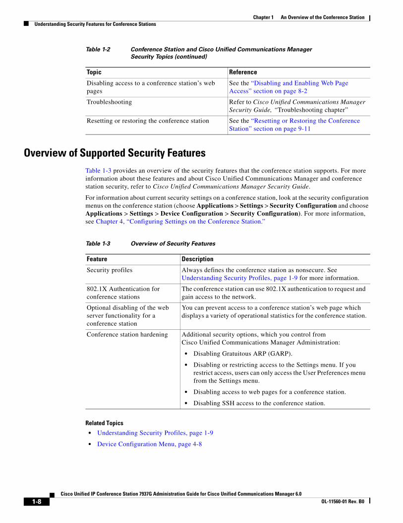
Overview of Supported Security FeaturesTable 1-3 provides an overview of the security features that the conference station supports. For more information about these features and about Cisco Unified Communications Manager and conference station security, refer to Cisco Unified Communications Manager Security Guide.
For information about current security settings on a conference station, look at the security configuration menus on the conference station (choose Applications > Settings > Security Configuration and choose Applications > Settings > Device Configuration > Security Configuration). For more information, see Chapter 4, “Configuring Settings on the Conference Station.”
Related Topics
• Understanding Security Profiles, page 1-9
• Device Configuration Menu, page 4-8
Disabling access to a conference station’s web pages
See the “Disabling and Enabling Web Page Access” section on page 8-2
Troubleshooting Refer to Cisco Unified Communications Manager Security Guide, “Troubleshooting chapter”
Resetting or restoring the conference station See the “Resetting or Restoring the Conference Station” section on page 9-11
Table 1-2 Conference Station and Cisco Unified Communications Manager Security Topics (continued)
Topic Reference
Table 1-3 Overview of Security Features
Feature Description
Security profiles Always defines the conference station as nonsecure. See Understanding Security Profiles, page 1-9 for more information.
802.1X Authentication for conference stations
The conference station can use 802.1X authentication to request and gain access to the network.
Optional disabling of the web server functionality for a conference station
You can prevent access to a conference station’s web page which displays a variety of operational statistics for the conference station.
Conference station hardening Additional security options, which you control from Cisco Unified Communications Manager Administration:
• Disabling Gratuitous ARP (GARP).
• Disabling or restricting access to the Settings menu. If you restrict access, users can only access the User Preferences menu from the Settings menu.
• Disabling access to web pages for a conference station.
• Disabling SSH access to the conference station.
1-8Cisco Unified IP Conference Station 7937G Administration Guide for Cisco Unified Communications Manager 6.0
OL-11560-01 Rev. B0
Chapter 1 An Overview of the Conference StationOverview of Configuring and Installing Conference Stations
Understanding Security ProfilesAll conference stations that support Cisco Unified Communications Manager use a security profile which defines the conference station as nonsecure. For information about the security profile, refer to Cisco Unified Communications Manager Security Guide, Release 6.0.
Overview of Configuring and Installing Conference StationsWhen deploying a new IP telephony system, system administrators and network administrators must complete several initial configuration tasks to prepare the network for IP telephony service. For information and a checklist for setting up and configuring a complete Cisco IP telephony network, refer to the “System Configuration Overview” chapter in Cisco Unified Communications Manager System Guide.
After you have set up the IP telephony system and configured system-wide features in Cisco Unified Communications Manager, you can add conference stations to the system.
The following topics provide an overview of procedures for adding conference stations to your network:
• Configuring Conference Stations in Cisco Unified Communications Manager, page 1-9
• Installing Conference Stations, page 1-12
Configuring Conference Stations in Cisco Unified Communications ManagerTo add conference stations to the Cisco Unified Communications Manager database, you can use:
• Auto-registration
• Cisco Unified Communications Manager Administration
• Bulk Administration Tool (BAT)
• BAT and the Tool for Auto-Registered Phones Support (TAPS)
For more information about these choices, see the “Adding Conference Stations to the Cisco Unified Communications Manager Database” section on page 2-7.
For general information about configuring conference stations in Cisco Unified Communications Manager, refer to the “Cisco Unified IP Phones” chapter in Cisco Unified Communications Manager System Guide.
1-9Cisco Unified IP Conference Station 7937G Administration Guide for Cisco Unified Communications Manager 6.0
OL-11560-01 Rev. B0
Chapter 1 An Overview of the Conference StationOverview of Configuring and Installing Conference Stations
Checklist for Configuring the Conference Station in Cisco Unified Communications Manager
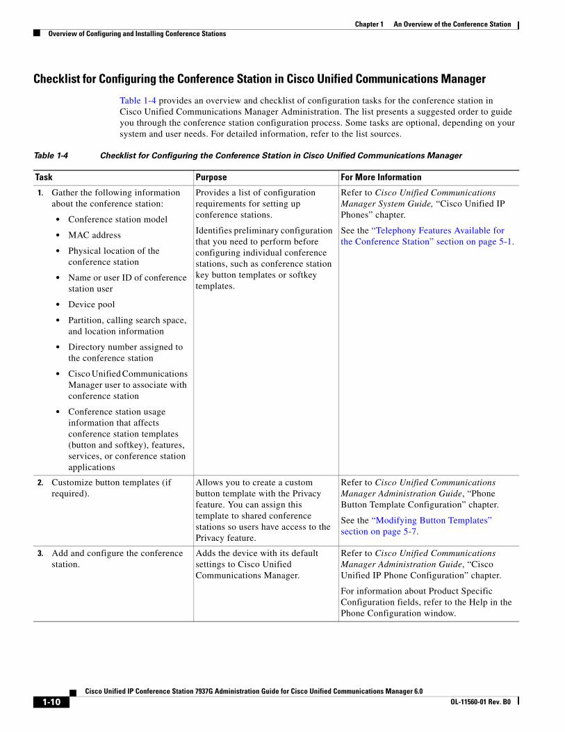
Table 1-4 provides an overview and checklist of configuration tasks for the conference station in Cisco Unified Communications Manager Administration. The list presents a suggested order to guide you through the conference station configuration process. Some tasks are optional, depending on your system and user needs. For detailed information, refer to the list sources.
Table 1-4 Checklist for Configuring the Conference Station in Cisco Unified Communications Manager
Task Purpose For More Information
1. Gather the following information about the conference station:
• Conference station model
• MAC address
• Physical location of the conference station
• Name or user ID of conference station user
• Device pool
• Partition, calling search space, and location information
• Directory number assigned to the conference station
• Cisco Unified Communications Manager user to associate with conference station
• Conference station usage information that affects conference station templates (button and softkey), features, services, or conference station applications
Provides a list of configuration requirements for setting up conference stations.
Identifies preliminary configuration that you need to perform before configuring individual conference stations, such as conference station key button templates or softkey templates.
Refer to Cisco Unified Communications Manager System Guide, “Cisco Unified IP Phones” chapter.
See the “Telephony Features Available for the Conference Station” section on page 5-1.
2. Customize button templates (if required).
Allows you to create a custom button template with the Privacy feature. You can assign this template to shared conference stations so users have access to the Privacy feature.
Refer to Cisco Unified Communications Manager Administration Guide, “Phone Button Template Configuration” chapter.
See the “Modifying Button Templates” section on page 5-7.
3. Add and configure the conference station.
Adds the device with its default settings to Cisco Unified Communications Manager.
Refer to Cisco Unified Communications Manager Administration Guide, “Cisco Unified IP Phone Configuration” chapter.
For information about Product Specific Configuration fields, refer to the Help in the Phone Configuration window.
1-10Cisco Unified IP Conference Station 7937G Administration Guide for Cisco Unified Communications Manager 6.0
OL-11560-01 Rev. B0
Chapter 1 An Overview of the Conference StationOverview of Configuring and Installing Conference Stations
4. Add and configure the directory number on the conference station.
Adds the directory number and features associated with the directory number to the conference station.
Refer to Cisco Unified Communications Manager Administration Guide, “Cisco Unified IP Phone Configuration” chapter, “Directory Number Configuration” and “Creating a Cisco Unity Voice Mailbox” sections.
See the “Telephony Features Available for the Conference Station” section on page 5-1.
5. Customize softkey templates. Adds, deletes, or changes order of softkey features that display on the user’s conference station to meet feature usage needs.
Refer to Cisco Unified Communications Manager Administration Guide, “Softkey Template Configuration” chapter.
See the “Configuring Softkey Templates” section on page 5-8.
6. Assign speed-dial numbers (optional).
Adds speed-dial numbers.
Note Users can change speed-dial settings on their conference stations by using the User Options web pages.
Refer to:
• Cisco Unified Communications Manager Administration Guide, “Cisco Unified IP Phone Configuration” chapter.
• Cisco Unified Communications Manager System Guide, “Cisco Unified IP Phones” chapter.
7. Configure conference station services and assign services (optional).
Provides conference station services.
Note Users can add or change services on their conference stations by using the User Options web pages.
Refer to Cisco Unified Communications Manager Administration Guide, “Cisco Unified IP Phone Services Configuration” chapter.
See the “Setting Up Services” section on page 5-8.
8. Add user information. Adds user information to the global directory for Cisco Unified Communications Manager.
Refer to Cisco Unified Communications Manager Administration Guide, “Adding a New User” chapter.
See the “Adding Users to Cisco Unified Communications Manager” section on page 5-9.
9. Associate a user and a user group with a conference station.
Provides users with control over their conference station such as forwarding calls or adding speed-dial numbers or services.
Note Some conference stations, such as those in conference rooms, do not have an associated user.
Refer to Cisco Unified Communications Manager Administration Guide, “Adding a New User” chapter, “Associating Devices to a User” section.
Table 1-4 Checklist for Configuring the Conference Station in Cisco Unified Communications Manager (continued)
Task Purpose For More Information
1-11Cisco Unified IP Conference Station 7937G Administration Guide for Cisco Unified Communications Manager 6.0
OL-11560-01 Rev. B0
Chapter 1 An Overview of the Conference StationOverview of Configuring and Installing Conference Stations
Installing Conference StationsAfter you have added the conference stations to the Cisco Unified Communications Manager database, you can complete the conference station installation. You (or the conference station users) can install the conference station at the users’s location. The Cisco Unified IP Conference Station 7937G Installation Guide provides directions for connecting the conference station to the network, and connecting any optional accessories to the conference station. You can access the guide at the following URL:
http://www.cisco.com/en/US/products/hw/phones/ps379/tsd_products_support_series_home.html
After the conference station is connected to the network, the conference station startup process begins and the conference station registers with Cisco Unified Communications Manager. To finish installing the conference station, configure the network settings on the conference station depending on whether you enable or disable DHCP service.
If you used auto-registration, you need to update the specific configuration information for the conference station such as associating the conference station with a user, changing the button table, or directory number.
Checklist for Installing the Conference Station
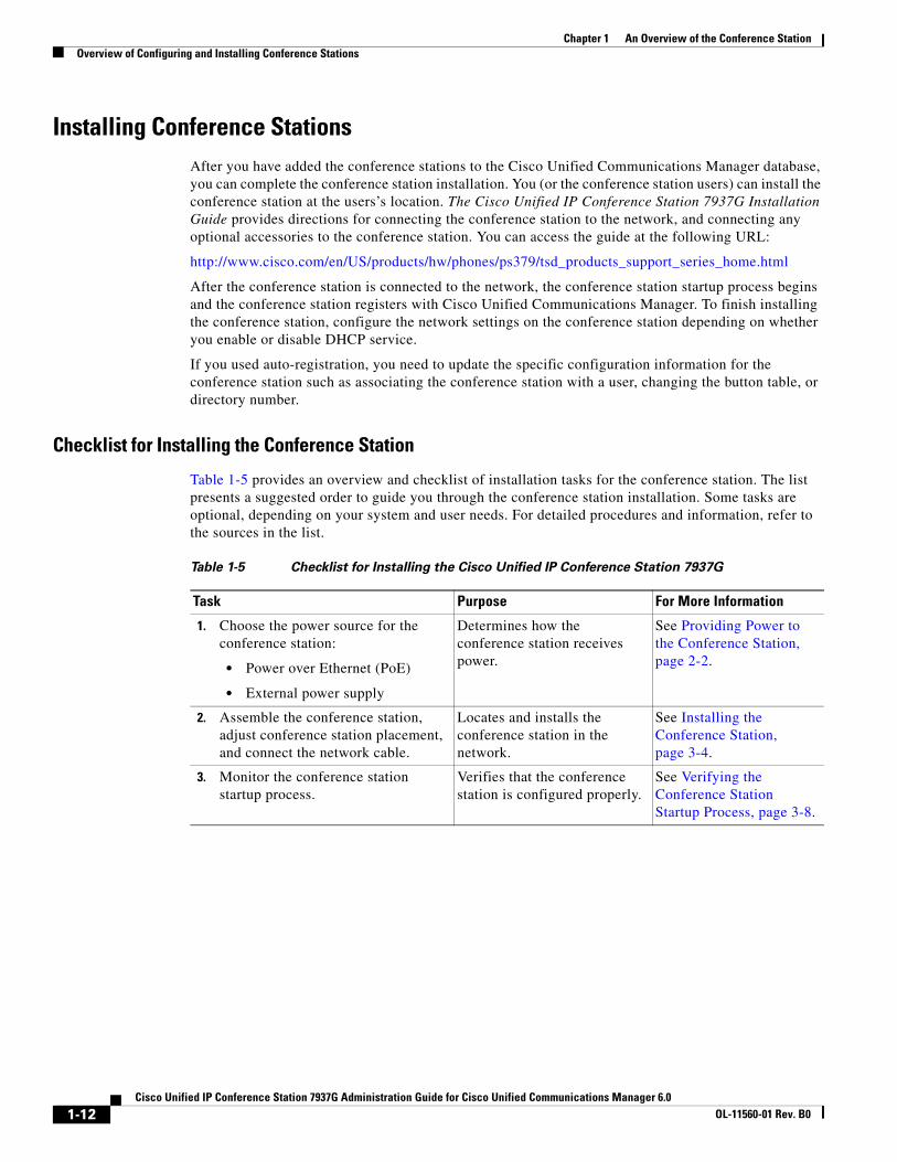
Table 1-5 provides an overview and checklist of installation tasks for the conference station. The list presents a suggested order to guide you through the conference station installation. Some tasks are optional, depending on your system and user needs. For detailed procedures and information, refer to the sources in the list.
Table 1-5 Checklist for Installing the Cisco Unified IP Conference Station 7937G
Task Purpose For More Information
1. Choose the power source for the conference station:
• Power over Ethernet (PoE)
• External power supply
Determines how the conference station receives power.
See Providing Power to the Conference Station, page 2-2.
2. Assemble the conference station, adjust conference station placement, and connect the network cable.
Locates and installs the conference station in the network.
See Installing the Conference Station, page 3-4.
3. Monitor the conference station startup process.
Verifies that the conference station is configured properly.
See Verifying the Conference Station Startup Process, page 3-8.
1-12Cisco Unified IP Conference Station 7937G Administration Guide for Cisco Unified Communications Manager 6.0
OL-11560-01 Rev. B0

Chapter 1 An Overview of the Conference StationOverview of Configuring and Installing Conference Stations
4. Configure these network settings on the conference station by choosing Applications > Settings > Network Configuration.
To enable DHCP:
a. Set DHCP Enabled to Yes.
b. To use an alternate TFTP server, set Alternate TFTP to Yes.
c. Enter an IP address for TFTP Server 1.
To disable DHCP:
a. Set DHCP Enabled to No.
b. Enter a static IP address for the conference station.
c. Enter the Subnet Mask.
d. Enter the IP address for Default Router 1.
e. Enter the Domain Name where the conference station resides.
f. Set Alternate TFTP to Yes.
g. Enter an IP address for TFTP Server 1.
Using DHCP—The IP address is automatically assigned and the conference station is directed to a TFTP Server.
Note Consult with the network administrator if you need to assign an alternative TFTP server instead of using the TFTP server assigned by DHCP.
Without DHCP—You must configure the IP address, TFTP server, subnet mask, domain name, and default router locally on the conference station.
See the “Configuring Startup Network Settings” section on page 3-9.
See the “Network Configuration Menu” section on page 4-5.
5. Set up security on the conference station.
Provides protection against data tampering threats and identity theft of conference stations.
See the “Security Configuration Menu” section on page 4-11.
See the “Security Configuration Menu” section on page 4-12.
6. Make calls with the conference station.
Verifies that the conference station and features work correctly.
Refer to Cisco Unified IP Conference Station 7937G Phone Guide for Cisco Unified Communications Manager 6.0.
7. Provide information to end users about how to use their conference stations and how to configure their conference station options.
Ensures that users have adequate information to successfully use their conference stations.
See Appendix A, “Providing Information to Users Via a Website.”
Table 1-5 Checklist for Installing the Cisco Unified IP Conference Station 7937G (continued)
Task Purpose For More Information
1-13Cisco Unified IP Conference Station 7937G Administration Guide for Cisco Unified Communications Manager 6.0
OL-11560-01 Rev. B0

Chapter 1 An Overview of the Conference StationOverview of Configuring and Installing Conference Stations
1-14Cisco Unified IP Conference Station 7937G Administration Guide for Cisco Unified Communications Manager 6.0
OL-11560-01 Rev. B0
Cisco Unified IP Conference Station 7937 Administration GuOL-11560-01 Rev. B0
C H A P T E R 2
Preparing to Install the Conference Station on Your NetworkThe Cisco Unified IP Conference Station 7937G enables you to communicate using voice over a data network. To provide this capability, the conference stations depend upon and interact with several other key Cisco Internet Protocol (IP) Telephony and network components, including Cisco Unified Communications Manager 6.0, Domain Name System (DNS) and Dynamic Host Configuration Protocol (DHCP) servers, Trivial File Transfer Protocol (TFTP) servers, media resources, and so on.
This chapter focuses on the interactions between the conference station and Cisco Unified Communications Manager, DNS and DHCP servers, TFTP servers, and switches. It also describes options for powering conference stations.
For related information about voice and IP communications, refer to this URL:
http://www.cisco.com/en/US/partner/products/sw/voicesw/index.html
This chapter provides an overview of the interaction between the conference station and other key components of a Voice over IP (VoIP) network. It covers these topics:
• Understanding Interactions with Other Cisco Unified IP Communications Products, page 2-1
• Providing Power to the Conference Station, page 2-2
• Understanding Conference Station Configuration Files, page 2-4
• Understanding the Conference Station Startup Process, page 2-5
• Adding Conference Stations to the Cisco Unified Communications Manager Database, page 2-7
• Determining the MAC Address of a Conference Station, page 2-9
Understanding Interactions with Other Cisco Unified IP Communications Products
To function in the IP telephony network, the conference station must be connected to a networking device, such as a Cisco Catalyst switch. You must also register the conference station with a Cisco Unified Communications Manager system before sending and receiving calls.
This section includes the following topic:
• Understanding How the Conference Station Interacts with Cisco Unified Communications Manager, page 2-2
2-1ide for Cisco Unified Communications Manager 6.0
Chapter 2 Preparing to Install the Conference Station on Your NetworkProviding Power to the Conference Station
Understanding How the Conference Station Interacts with Cisco Unified Communications Manager
Cisco Unified Communications Manager is an open and industry-standard call processing system. Cisco Unified Communications Manager software sets up and tears down calls between conference stations, integrating traditional private branch exchange (PBX) functionality with the corporate IP network. Cisco Unified Communications Manager manages the components of the IP telephony system—the conference stations, the access gateways, and the resources necessary for such features as call conferencing and route planning. Cisco Unified Communications Manager also provides:
• Firmware for conference stations
• Authentication and encryption (if configured for the telephony system)
• Configuration file
• Conference station registration
• Call preservation, so that a media session continues if signaling is lost between the primary Cisco Unified Communications Manager and a conference station
For information about configuring Cisco Unified Communications Manager to work with the IP devices described in this chapter, refer to Cisco Unified Communications Manager Administration Guide, Cisco Unified Communications Manager System Guide, and to Cisco Unified Communications Manager Security Guide.
For an overview of security functionality for the conference station, see the “Understanding Security Features for Conference Stations” section on page 1-7.
Note If the conference station model that you want to configure does not appear in the Phone Type drop-down list in Cisco Unified Communications Manager Administration, go to the following URL and install the latest support patch for your version of Cisco Unified Communications Manager: http://www.cisco.com/kobayashi/sw-center/sw-voice.shtml
Related Topic
• Telephony Features Available for the Conference Station, page 5-1
Providing Power to the Conference Station The conference station can be powered with external power or with Power over Ethernet (PoE). External power is provided through a separate power supply. PoE is provided by a switch through the Ethernet cable attached to a conference station.
Note When you install a conference station that is powered by an optional external power supply, do the following:
• Use a power interface cable to attach to the PoE cable and LAN wall port. See the “Installing the Conference Station” section on page 3-4 for instructions on how to attach the power interface cable.
• Connect the power supply to the conference station and to a power outlet before you connect the Ethernet cable to the conference station. When you remove a conference station that is powered with external power, disconnect the Ethernet cable from the conference station before you disconnect the power supply.
2-2Cisco Unified IP Conference Station 7937 Administration Guide for Cisco Unified Communications Manager 6.0
OL-11560-01 Rev. B0

Chapter 2 Preparing to Install the Conference Station on Your NetworkProviding Power to the Conference Station
These sections provide more information about powering a conference station:
• Power Guidelines, page 2-3
• Conference Station Power Consumption and Display Brightness, page 2-3
• Power Outage, page 2-4
• Obtaining Additional Information about Power, page 2-4
Power GuidelinesTable 2-1 provides guidelines that apply to external power and to PoE power for conference stations.
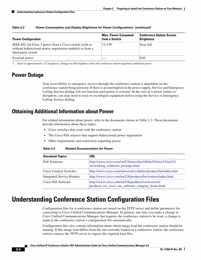
Conference Station Power Consumption and Display BrightnessThe power consumed by a conference station depends on its power configuration. See Table 2-1 for a power configuration overview. See Table 2-2 for the maximum power consumed by a conference station for each configuration option and the correlating conference station screen brightness level.
Note Power consumption values shown in the table include power losses in the cable that connects the conference station to the switch.
Table 2-1 Guidelines for Powering the Conference Station
Power Type Guidelines
External power—Provided by an external power supply
• The conference station is rated 48 V DC, 0.375 A. When you use the conference station with an optional external power supply, the power supply must be a listed power supply with a Limited Power Source (LPS) output that is rated 48 V, min 0.375 A.
PoE power—Provided by a switch through the Ethernet cable attached to the conference station
• The inline power patch panel WS-PWR-PANEL is not compatible with the conference station.
• To ensure uninterrupted operation of the conference station, make sure that the switch has a backup power supply.
• Make sure that the CatOS or IOS version running on your switch supports your intended conference station deployment. Refer to the documentation for your switch for operating system version information.
Table 2-2 Power Consumption and Display Brightness for Power Configurations
Power ConfigurationMax. Power Consumed from a Switch
Conference Station Screen Brightness
IEEE 802.3af Class 3 power from a Cisco switch, without bidirectional power negotiation
6.3 W Approx. 1/2
IEEE 802.3af Class 3 power from a third-party switch 6.3 W Approx. 1/2
IEEE 802.3af Class 3 power from a Cisco switch, with bidirectional power negotiation enabled
10.25 W Full1
2-3Cisco Unified IP Conference Station 7937 Administration Guide for Cisco Unified Communications Manager 6.0
OL-11560-01 Rev. B0
Chapter 2 Preparing to Install the Conference Station on Your NetworkUnderstanding Conference Station Configuration Files
Power OutageYour accessibility to emergency service through the conference station is dependent on the conference station being powered. If there is an interruption in the power supply, Service and Emergency Calling Service dialing will not function until power is restored. In the case of a power failure or disruption, you may need to reset or reconfigure equipment before using the Service or Emergency Calling Service dialing.
Obtaining Additional Information about PowerFor related information about power, refer to the documents shown in Table 2-3. These documents provide information about these topics:
• Cisco switches that work with the conference station
• The Cisco IOS releases that support bidirectional power negotiation
• Other requirements and restrictions regarding power
Understanding Conference Station Configuration FilesConfiguration files for a conference station are stored on the TFTP server and define parameters for connecting to Cisco Unified Communications Manager. In general, any time you make a change in Cisco Unified Communications Manager that requires the conference station to be reset, a change is made to the conference station’s configuration file automatically.
Configuration files also contain information about which image load the conference station should be running. If this image load differs from the one currently loaded on a conference station, the conference station contacts the TFTP server to request the required load files.
IEEE 802.3af Class 3 power from a Cisco switch (with or without bidirectional power negotiation enabled) or from a third-party switch
15.4 W Near full
External power — Full
1. Starts at approximately 1/2 brightness, changes to full brightness when the conference station negotiates additional power.
Table 2-2 Power Consumption and Display Brightness for Power Configurations (continued)
Power ConfigurationMax. Power Consumed from a Switch
Conference Station Screen Brightness
Table 2-3 Related Documentation for Power
Document Topics URL
PoE Solutions http://www.cisco.com/en/US/netsol/ns340/ns394/ns147/ns412/ networking_solutions_package.html
Cisco Catalyst Switches http://www.cisco.com/univercd/cc/td/doc/product/lan/index.htm
Integrated Service Routers http://www.cisco.com/en/US/products/hw/routers/index.html
Cisco IOS Software http://www.cisco.com/en/US/products/sw/iosswrel/ products_ios_cisco_ios_software_category_home.html
2-4Cisco Unified IP Conference Station 7937 Administration Guide for Cisco Unified Communications Manager 6.0
OL-11560-01 Rev. B0
Chapter 2 Preparing to Install the Conference Station on Your NetworkUnderstanding the Conference Station Startup Process
A conference station accesses a default configuration file named XmlDefault.cnf.xml from the TFTP server when these conditions exist:
• You have enabled auto-registration in Cisco Unified Communications Manager
• The conference station has not been added to the Cisco Unified Communications Manager Database
• The conference station is registering for the first time
If auto registration is not enabled and the conference station has not been added to the Cisco Unified Communications Manager Database, the conference station registration request will be rejected. In this case, the conference station will reset and attempt to register repeatedly.
If the conference station has registered before, the conference station will access the configuration file named SEPmac_address.cnf.xml, where mac_address is the Media Access Control (MAC) address of the conference station.
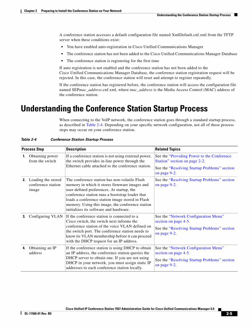
Understanding the Conference Station Startup ProcessWhen connecting to the VoIP network, the conference station goes through a standard startup process, as described in Table 2-4. Depending on your specific network configuration, not all of these process steps may occur on your conference station.
Table 2-4 Conference Station Startup Process
Process Step Description Related Topics
1. Obtaining power from the switch
If a conference station is not using external power, the switch provides in-line power through the Ethernet cable attached to the conference station.
See the “Providing Power to the Conference Station” section on page 2-2.
See the “Resolving Startup Problems” section on page 9-2.
2. Loading the stored conference station image
The conference station has non-volatile Flash memory in which it stores firmware images and user-defined preferences. At startup, the conference station runs a bootstrap loader that loads a conference station image stored in Flash memory. Using this image, the conference station initializes its software and hardware.
See the “Resolving Startup Problems” section on page 9-2.
3. Configuring VLAN If the conference station is connected to a Cisco switch, the switch next informs the conference station of the voice VLAN defined on the switch port. The conference station needs to know its VLAN membership before it can proceed with the DHCP request for an IP address.
See the “Network Configuration Menu” section on page 4-5.
See the “Resolving Startup Problems” section on page 9-2.
4. Obtaining an IP address
If the conference station is using DHCP to obtain an IP address, the conference station queries the DHCP server to obtain one. If you are not using DHCP in your network, you must assign static IP addresses to each conference station locally.
See the “Network Configuration Menu” section on page 4-5.
See the “Resolving Startup Problems” section on page 9-2.
2-5Cisco Unified IP Conference Station 7937 Administration Guide for Cisco Unified Communications Manager 6.0
OL-11560-01 Rev. B0
Chapter 2 Preparing to Install the Conference Station on Your NetworkUnderstanding the Conference Station Startup Process
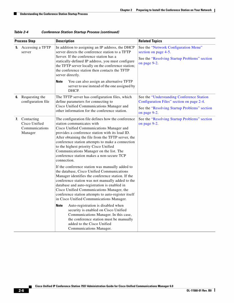
5. Accessing a TFTP server
In addition to assigning an IP address, the DHCP server directs the conference station to a TFTP Server. If the conference station has a statically-defined IP address, you must configure the TFTP server locally on the conference station; the conference station then contacts the TFTP server directly.
Note You can also assign an alternative TFTP server to use instead of the one assigned by DHCP.
See the “Network Configuration Menu” section on page 4-5.
See the “Resolving Startup Problems” section on page 9-2.
6. Requesting the configuration file
The TFTP server has configuration files, which define parameters for connecting to Cisco Unified Communications Manager and other information for the conference station.
See the “Understanding Conference Station Configuration Files” section on page 2-4.
See the “Resolving Startup Problems” section on page 9-2.
7. Contacting Cisco Unified Communications Manager
The configuration file defines how the conference station communicates with Cisco Unified Communications Manager and provides a conference station with its load ID. After obtaining the file from the TFTP server, the conference station attempts to make a connection to the highest priority Cisco Unified Communications Manager on the list. The conference station makes a non-secure TCP connection.
If the conference station was manually added to the database, Cisco Unified Communications Manager identifies the conference station. If the conference station was not manually added to the database and auto-registration is enabled in Cisco Unified Communications Manager, the conference station attempts to auto-register itself in Cisco Unified Communications Manager.
Note Auto-registration is disabled when security is enabled on Cisco Unified Communications Manager. In this case, the conference station must be manually added to the Cisco Unified Communications Manager.
See the “Resolving Startup Problems” section on page 9-2.
Table 2-4 Conference Station Startup Process (continued)
Process Step Description Related Topics
2-6Cisco Unified IP Conference Station 7937 Administration Guide for Cisco Unified Communications Manager 6.0
OL-11560-01 Rev. B0
Chapter 2 Preparing to Install the Conference Station on Your NetworkAdding Conference Stations to the Cisco Unified Communications Manager Database
Adding Conference Stations to the Cisco Unified Communications Manager Database
Before installing the conference station, you must choose a method for adding conference stations to Cisco Unified Communications Manager. These sections describe the methods:
• Adding Conference Stations with Auto-Registration, page 2-7
• Adding Conference Stations with Auto-Registration and TAPS, page 2-8
• Adding Conference Stations with Cisco Unified Communications Manager Administration, page 2-9
• Adding Conference Stations with BAT, page 2-9
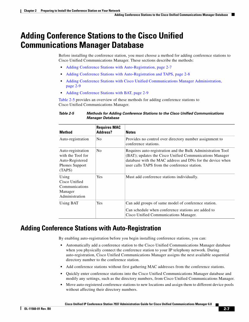
Table 2-5 provides an overview of these methods for adding conference stations to Cisco Unified Communications Manager.
Adding Conference Stations with Auto-RegistrationBy enabling auto-registration before you begin installing conference stations, you can:
• Automatically add a conference station to the Cisco Unified Communications Manager database when you physically connect the conference station to your IP telephony network. During auto-registration, Cisco Unified Communications Manager assigns the next available sequential directory number to the conference station.
• Add conference stations without first gathering MAC addresses from the conference stations.
• Quickly enter conference stations into the Cisco Unified Communications Manager database and modify any settings, such as the directory numbers, from Cisco Unified Communications Manager.
• Move auto-registered conference stations to new locations and assign them to different device pools without affecting their directory numbers.
Table 2-5 Methods for Adding Conference Stations to the Cisco Unified Communications
Manager Database
MethodRequires MAC Address? Notes
Auto-registration No Provides no control over directory number assignment to conference stations.
Auto-registration with the Tool for Auto-Registered Phones Support (TAPS)
No Requires auto-registration and the Bulk Administration Tool (BAT); updates the Cisco Unified Communications Manager database with the MAC address and DNs for the device when user calls TAPS from the conference station.
Using Cisco Unified Communications Manager Administration
Yes Must add conference stations individually.
Using BAT Yes Can add groups of same model of conference station.
Can schedule when conference stations are added to Cisco Unified Communications Manager.
2-7Cisco Unified IP Conference Station 7937 Administration Guide for Cisco Unified Communications Manager 6.0
OL-11560-01 Rev. B0
Chapter 2 Preparing to Install the Conference Station on Your NetworkAdding Conference Stations to the Cisco Unified Communications Manager Database
Note You should use auto-registration to add less than 100 conference stations to your network. To add more than 100 conference stations to your network, use BAT. See the “Adding Conference Stations with BAT” section on page 2-9.
In some cases, you might not want to use auto-registration: for example, if you want to assign a specific directory number to the conference station or if you plan to implement authentication or encryption, as described in Cisco Unified Communications Manager Security Guide.
For information about enabling auto-registration, refer to “Enabling Auto-Registration” in the Cisco Unified Communications Manager Administration Guide.
Related Topics
• Adding Conference Stations with Auto-Registration and TAPS, page 2-8
• Adding Conference Stations with Cisco Unified Communications Manager Administration, page 2-9
• Adding Conference Stations with BAT, page 2-9
Adding Conference Stations with Auto-Registration and TAPSYou can add conference stations with auto-registration and TAPS without first gathering MAC addresses from conference stations.
TAPS works with BAT to update a batch of conference stations that were already added to the Cisco Unified Communications Manager database with dummy MAC addresses. You use TAPS to update MAC addresses and download pre-defined configurations for conference stations.
Note Cisco recommends you use auto-registration and TAPS to add less than 100 conference stations to your network. To add more than 100 conference stations to your network, use the Bulk Administration Tool (BAT). See the “Adding Conference Stations with BAT” section on page 2-9.
To implement TAPS, you or the end-user dial a TAPS directory number and follow voice prompts. When the process is complete, the conference station will have downloaded its directory number and other settings, and the conference station will be updated in Cisco Unified Communications Manager Administration with the correct MAC address.
Auto-registration must be enabled in Cisco Unified Communications Manager Administration for TAPS to function.
Refer to Cisco Unified Communications Manager Bulk Administration Guide for detailed instructions about BAT and TAPS.
Related Topics
• Adding Conference Stations with Auto-Registration, page 2-7
• Adding Conference Stations with Cisco Unified Communications Manager Administration, page 2-9
• Adding Conference Stations with BAT, page 2-9
2-8Cisco Unified IP Conference Station 7937 Administration Guide for Cisco Unified Communications Manager 6.0
OL-11560-01 Rev. B0
Chapter 2 Preparing to Install the Conference Station on Your NetworkDetermining the MAC Address of a Conference Station
Adding Conference Stations with Cisco Unified Communications Manager Administration
You can add conference stations individually to the Cisco Unified Communications Manager database using Cisco Unified Communications Manager Administration. To do so, you first need to obtain the MAC address for each conference station.
For information about determining a MAC address, see the “Determining the MAC Address of a Conference Station” section on page 2-9.
After you collect MAC addresses, in Cisco Unified Communications Manager Administration, choose Device > Phone, and then click Add New to begin.
For complete instructions and conceptual information about Cisco Unified Communications Manager, refer to Cisco Unified Communications Manager Administration Guide and to Cisco Unified Communications Manager System Guide.
Related Topics
• Adding Conference Stations with Auto-Registration, page 2-7
• Adding Conference Stations with Auto-Registration and TAPS, page 2-8
• Adding Conference Stations with BAT, page 2-9
Adding Conference Stations with BATThe Cisco BAT enables you to perform batch operations, including registration, on multiple conference stations.
Before you can add conference stations using BAT only (not in conjunction with TAPS), you must obtain the MAC address for each conference station.
For information about determining a MAC address, see the “Determining the MAC Address of a Conference Station” section on page 2-9.
For detailed instructions about using BAT, refer to Cisco Unified Communications Manager Administration Guide and to Cisco Unified Communications Manager Bulk Administration Guide.
Related Topics
• Adding Conference Stations with Auto-Registration, page 2-7
• Adding Conference Stations with Auto-Registration and TAPS, page 2-8
• Adding Conference Stations with Cisco Unified Communications Manager Administration, page 2-9
Determining the MAC Address of a Conference StationYou can determine the MAC address for a conference station in any of these ways:
• From the conference station, choose Applications > Settings > Model Information and look at the MAC Address field.
• Look at the MAC label on the back of the conference station.
• Display the conference station web page, and click the Device Information hyperlink.
For information about accessing the conference station web page, see the “Accessing the Web Page for a Conference Station” section on page 8-2.
2-9Cisco Unified IP Conference Station 7937 Administration Guide for Cisco Unified Communications Manager 6.0
OL-11560-01 Rev. B0

Chapter 2 Preparing to Install the Conference Station on Your NetworkDetermining the MAC Address of a Conference Station
2-10Cisco Unified IP Conference Station 7937 Administration Guide for Cisco Unified Communications Manager 6.0
OL-11560-01 Rev. B0
Cisco Unified IP Conference Station 7937G Administration GuOL-11560-01 Rev. B0
C H A P T E R 3
Setting Up the Conference StationThis chapter includes the following topics, which help you install the Cisco Unified IP Conference Station 7937G on an Internet Protocol (IP) telephony network:
• Before You Begin, page 3-1
• Understanding the Conference Station Components, page 3-3
• Installing the Conference Station, page 3-4
• Verifying the Conference Station Startup Process, page 3-8
• Configuring Startup Network Settings, page 3-9
Note Before you install a conference station, you must decide how to configure the conference station in your network. Then you can install the conference station and verify its functionality. For more information, see Chapter 2, “Preparing to Install the Conference Station on Your Network.”
Before You BeginBefore you install the conference station, review the requirements in these sections:
• Network Requirements, page 3-1
• Cisco Unified Communications Manager Configuration, page 3-2
• Safety, page 3-2
Network RequirementsFor the conference station to successfully operate as a conference station endpoint in your network, your network must meet these requirements:
• Working Voice over IP (VoIP) network:
– VoIP configured on your Cisco routers and gateways
– Cisco Unified Communications Manager Release 6.0 or later installed in your network and configured to handle call processing
• IP network that supports Dynamic Host Configuration Protocol (DHCP) or manual assignment of IP address, gateway, and subnet mask
3-1ide for Cisco Unified Communications Manager 6.0
Chapter 3 Setting Up the Conference StationBefore You Begin
Cisco Unified Communications Manager ConfigurationThe conference station requires Cisco Unified Communications Manager to handle call processing. Refer to Cisco Unified Communications Manager Administration Guide or to context-sensitive help in the Cisco Unified Communications Manager application to ensure that Cisco Unified Communications Manager is set up properly to manage the conference station and to properly route and process calls.
If you plan to use auto-registration, verify that it is enabled and properly configured in Cisco Unified Communications Manager before connecting any conference station to the network. For information about enabling and configuring auto-registration, refer to Cisco Unified Communications Manager Administration Guide. Also, see the “Adding Conference Stations to the Cisco Unified Communications Manager Database” section on page 2-7.
You must use Cisco Unified Communications Manager to configure and assign telephony features to the conference stations. See the “Telephony Features Available for the Conference Station” section on page 5-1 for details.
In Cisco Unified Communications Manager, you can add users to the database and associate them with specific conference stations. In this way, users gain access to web pages that allow them to configure items such as call forwarding, speed dialing, and voice messaging system options. See the “Adding Users to Cisco Unified Communications Manager” section on page 5-9 for details.
SafetyReview the following warnings before installing the conference station. To see translations of these warnings, refer to the Regulatory Compliance and Safety Information for Cisco Unified IP Conference Stations document that accompanied this device.
Warning Read the installation instructions before you connect the system to its power source.
Warning Only trained and qualified personnel should be allowed to install, replace, or service this equipment.
Warning Ultimate disposal of this product should be handled according to all national laws and regulations.
Warning Do not work on the system or connect or disconnect cables during periods of lightning activity.
Warning To avoid electric shock, do not connect safety extra low voltage (SELV) circuits to teleconference station network voltage (TNV) circuits. LAN ports contain SELV circuits, and WAN ports contain TNV circuits. Some LAN and WAN ports both use RJ-45 connectors. Use caution when connecting cables.
Caution Only use the proper Cisco approved external power supply. Reference the installation manual provided with the conference station.
3-2Cisco Unified IP Conference Station 7937G Administration Guide for Cisco Unified Communications Manager 6.0
OL-11560-01 Rev. B0
Chapter 3 Setting Up the Conference StationUnderstanding the Conference Station Components
The following warnings apply when you use an external power supply.
Warning This product relies on the building's installation for short-circuit (overcurrent) protection. Ensure that a fuse or circuit breaker no larger than 120 VAC, 15 A U.S. (240 VAC, 10 A international) is used on the phase conductors (all current-carrying conductors).
Warning The device is designed to work with TN power systems.
Warning The plug-socket combination must be accessible at all times because it serves as the main disconnecting device.
Understanding the Conference Station ComponentsThe conference station includes these components:
• Network Ports
• Audio Auxiliary Port
Network PortsThe underside of the conference station includes these connector ports:
• Ethernet network port (RJ-45)—Labeled “LAN”
• Two external microphone ports (mini-VGA)—Labeled with stenciled microphone icons
Each type of port supports 10/100 Mbps half- or full-duplex connections to external devices. You can use either Category 3 or 5 cabling for 10-Mbps connections, but you must use Category 5 for 100 Mbps connections.
Use the Ethernet network port to connect the conference station to the network. You must use a straight-through cable on this port. The conference station can also obtain inline power from a switch over this connection (Power over Ethernet). Figure 3-1 shows how to connect the conference station to the network using Power over Ethernet (PoE). If you use an external power source, rather than PoE, to connect the conference station to the network, see Figure 3-2. For more information on powering the conference station, see the “Providing Power to the Conference Station” section on page 2-2.
Use the external microphone ports to connect optional external microphones to the conference station. Figure 3-3 shows how to connect the optional microphones to the conference station.
3-3Cisco Unified IP Conference Station 7937G Administration Guide for Cisco Unified Communications Manager 6.0
OL-11560-01 Rev. B0

Chapter 3 Setting Up the Conference StationInstalling the Conference Station
Audio Auxiliary PortThe side of the conference station includes this port:
• Audio auxiliary port—Labeled with stenciled audio input/output symbol
The audio auxiliary port is on the right side of the conference station under a flap you flip open. Use the audio serial port to facilitate full-duplex connections to an optional mobile conference station device. You must use a straight-through cable on this port. Figure 3-4 shows how to connect the optional device to the conference station.
Installing the Conference StationYou must connect the conference station to the network and a power source before using it. If you choose, you can connect external microphones and a mobile conference station device to the conference station. For a graphical representation of the connections, see the following figures:
• Figure 3-1—Shows the connections using Power over Ethernet (PoE) power.
• Figure 3-2—Shows the connections using an optional external power supply.
• Figure 3-3—Shows the connection of optional external microphones to the conference station.
• Figure 3-4—Shows the connection of an optional mobile conference station device to the conference station.
Figure 3-1 shows how to connect the conference station to the network using PoE.
Figure 3-1 Conference Station Cable Connections Using PoE
1 Connection of network cable to conference station RJ-45 port
2 Network cable (25-foot)
3 Connection of network cable to LAN port
1
2
3
1852
59
3-4Cisco Unified IP Conference Station 7937G Administration Guide for Cisco Unified Communications Manager 6.0
OL-11560-01 Rev. B0
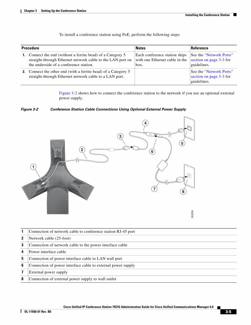
Chapter 3 Setting Up the Conference StationInstalling the Conference Station
To install a conference station using PoE, perform the following steps:
Figure 3-2 shows how to connect the conference station to the network if you use an optional external power supply.
Figure 3-2 Conference Station Cable Connections Using Optional External Power Supply
Procedure Notes Reference
1. Connect the end (without a ferrite bead) of a Category 5 straight-through Ethernet network cable to the LAN port on the underside of a conference station.
Each conference station ships with one Ethernet cable in the box.
See the “Network Ports” section on page 3-3 for guidelines.
2. Connect the other end (with a ferrite bead) of a Category 5 straight-through Ethernet network cable to a LAN port.
See the “Network Ports” section on page 3-3 for guidelines.
1 Connection of network cable to conference station RJ-45 port
2 Network cable (25-foot)
3 Connection of network cable to the power interface cable
4 Power interface cable
5 Connection of power interface cable to LAN wall port
6 Connection of power interface cable to external power supply
7 External power supply
8 Connection of external power supply to wall outlet
1
2
3
4
5
6
78
1852
58
3-5Cisco Unified IP Conference Station 7937G Administration Guide for Cisco Unified Communications Manager 6.0
OL-11560-01 Rev. B0
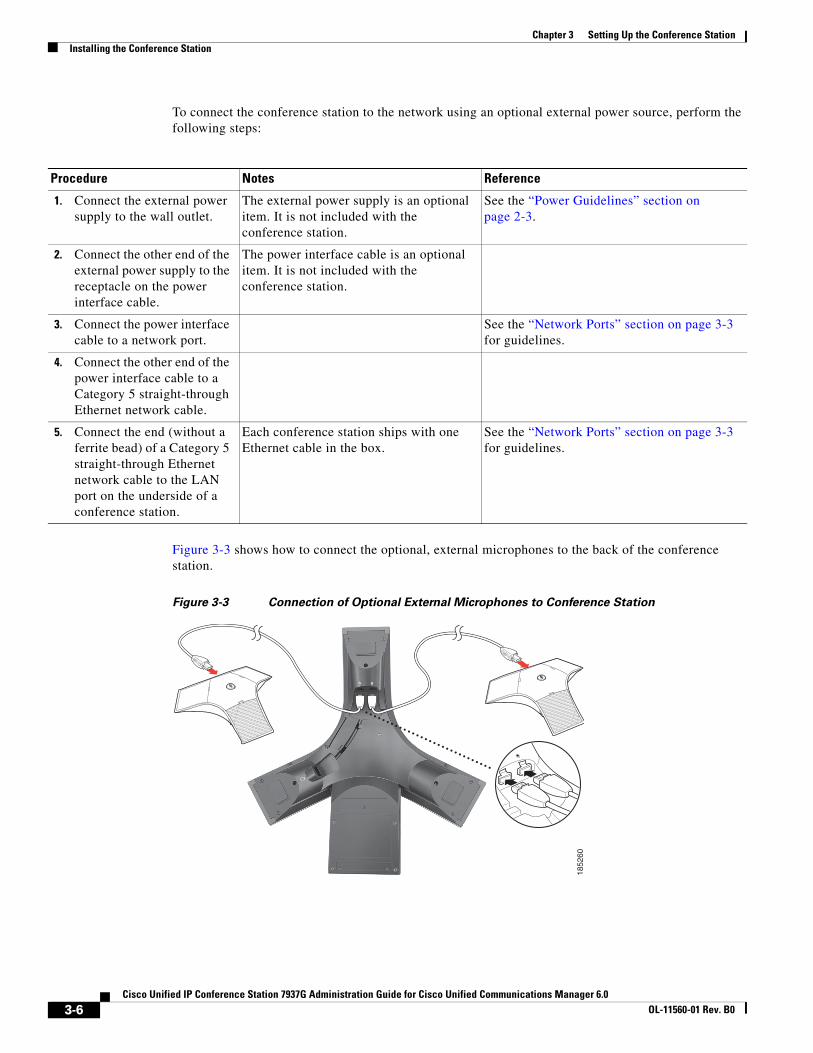
Chapter 3 Setting Up the Conference StationInstalling the Conference Station
To connect the conference station to the network using an optional external power source, perform the following steps:
Figure 3-3 shows how to connect the optional, external microphones to the back of the conference station.
Figure 3-3 Connection of Optional External Microphones to Conference Station
Procedure Notes Reference
1. Connect the external power supply to the wall outlet.
The external power supply is an optional item. It is not included with the conference station.
See the “Power Guidelines” section on page 2-3.
2. Connect the other end of the external power supply to the receptacle on the power interface cable.
The power interface cable is an optional item. It is not included with the conference station.
3. Connect the power interface cable to a network port.
See the “Network Ports” section on page 3-3 for guidelines.
4. Connect the other end of the power interface cable to a Category 5 straight-through Ethernet network cable.
5. Connect the end (without a ferrite bead) of a Category 5 straight-through Ethernet network cable to the LAN port on the underside of a conference station.
Each conference station ships with one Ethernet cable in the box.
See the “Network Ports” section on page 3-3 for guidelines.
1852
60
3-6Cisco Unified IP Conference Station 7937G Administration Guide for Cisco Unified Communications Manager 6.0
OL-11560-01 Rev. B0
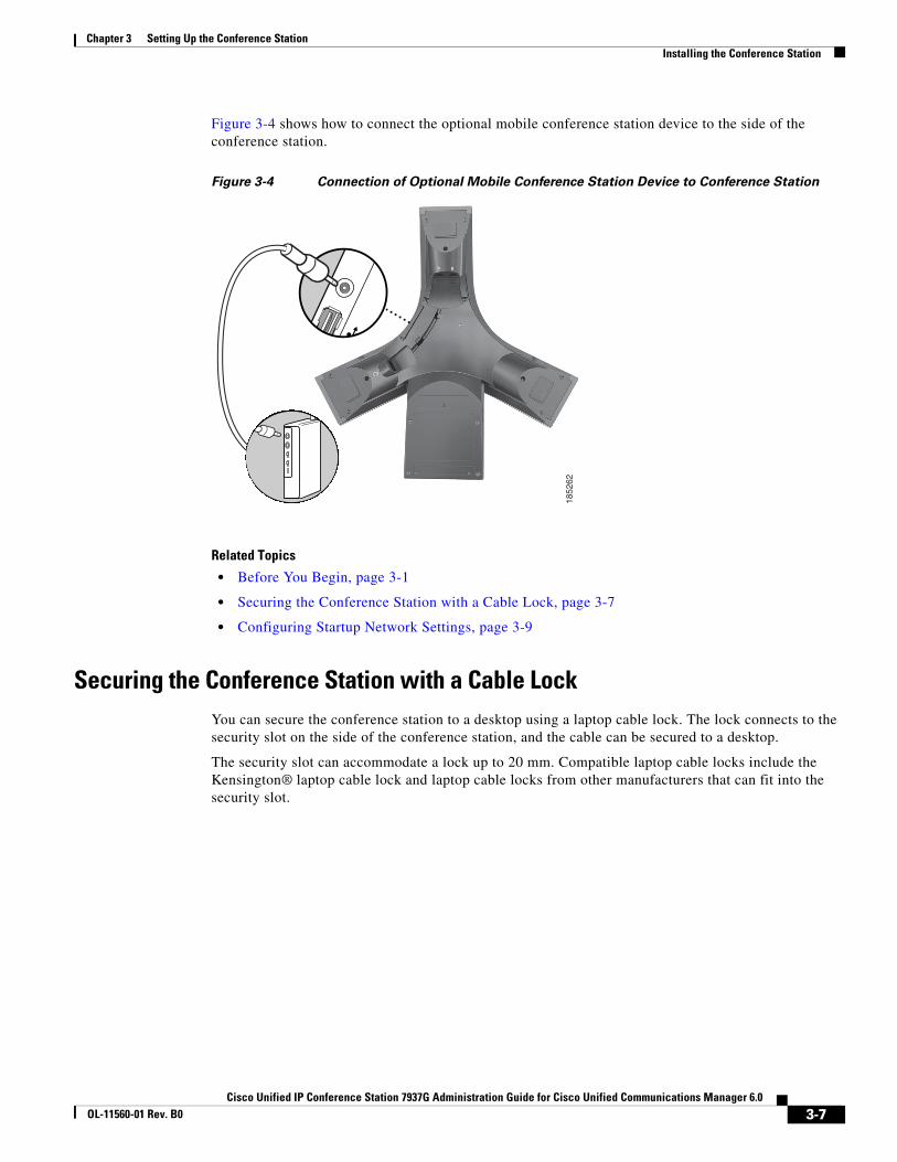
Chapter 3 Setting Up the Conference StationInstalling the Conference Station
Figure 3-4 shows how to connect the optional mobile conference station device to the side of the conference station.
Figure 3-4 Connection of Optional Mobile Conference Station Device to Conference Station
Related Topics
• Before You Begin, page 3-1
• Securing the Conference Station with a Cable Lock, page 3-7
• Configuring Startup Network Settings, page 3-9
Securing the Conference Station with a Cable LockYou can secure the conference station to a desktop using a laptop cable lock. The lock connects to the security slot on the side of the conference station, and the cable can be secured to a desktop.
The security slot can accommodate a lock up to 20 mm. Compatible laptop cable locks include the Kensington® laptop cable lock and laptop cable locks from other manufacturers that can fit into the security slot.
1852
62
3-7Cisco Unified IP Conference Station 7937G Administration Guide for Cisco Unified Communications Manager 6.0
OL-11560-01 Rev. B0
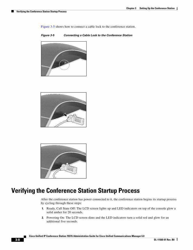
Chapter 3 Setting Up the Conference StationVerifying the Conference Station Startup Process
Figure 3-5 shows how to connect a cable lock to the conference station.
Figure 3-5 Connecting a Cable Lock to the Conference Station
Verifying the Conference Station Startup ProcessAfter the conference station has power connected to it, the conference station begins its startup process by cycling through these steps:
1. Ready, Call State Off: The LCD screen lights up and LED indicators on top of the console glow a solid amber for 20 seconds.
2. Powering On: The LCD screen dims and the LED indicators turn a solid red and glow for an additional five seconds.
3-8Cisco Unified IP Conference Station 7937G Administration Guide for Cisco Unified Communications Manager 6.0
OL-11560-01 Rev. B0
Chapter 3 Setting Up the Conference StationConfiguring Startup Network Settings
3. Power On: The LCD screen lights up and displays the Cisco logo.
4. The main conference station LCD screen displays the following details:
– Current date and time
– Directory number
– Softkeys
If the conference station successfully passes through these stages, it has started properly. If the conference station does not start properly, see the “Resolving Startup Problems” section on page 9-2.
Configuring Startup Network SettingsIf you are not using DHCP in your network, you must configure these network settings on the conference station after installing the conference station on the network:
• IP address
• Subnet mask
• Default gateway IP address
• TFTP server IP address
You also may configure the domain name and the DNS server settings, if necessary.
Collect this information and see the instructions in Chapter 4, “Configuring Settings on the Conference Station.”
Guidelines for Best PerformanceFollow these guidelines to ensure optimum performance with the conference station and the external microphones.
Note See the “Conference Room Setup Examples” section on page 3-10 for an illustration of proper equipment placement for different conference room configurations.
• Use the conference station in closed offices and conference rooms up to 20 feet by 20 feet (without external microphones) and 20 feet by 30 feet (with external microphones).
• Place the conference station base on a flat surface and make sure that it is clear from any reflective surfaces.
• Maintain a minimum distance of four feet between each external microphone and the conference station base and other objects.
• Make sure that all microphones are acoustically unobstructed.
• Position the external microphones toward the areas that need to be covered, and so that the main pickup direction is pointed away from the conference station.
• Seat all conference participants the same distance from the conference station.
• Speak at normal conversation levels and direct your voice toward the conference station.
• Do not move or handle the conference station base or the external microphones while on a call, and do not shuffle papers near the equipment.
• Minimize background noise from air conditioning units, fans, or other equipment in the office or conference room.
3-9Cisco Unified IP Conference Station 7937G Administration Guide for Cisco Unified Communications Manager 6.0
OL-11560-01 Rev. B0
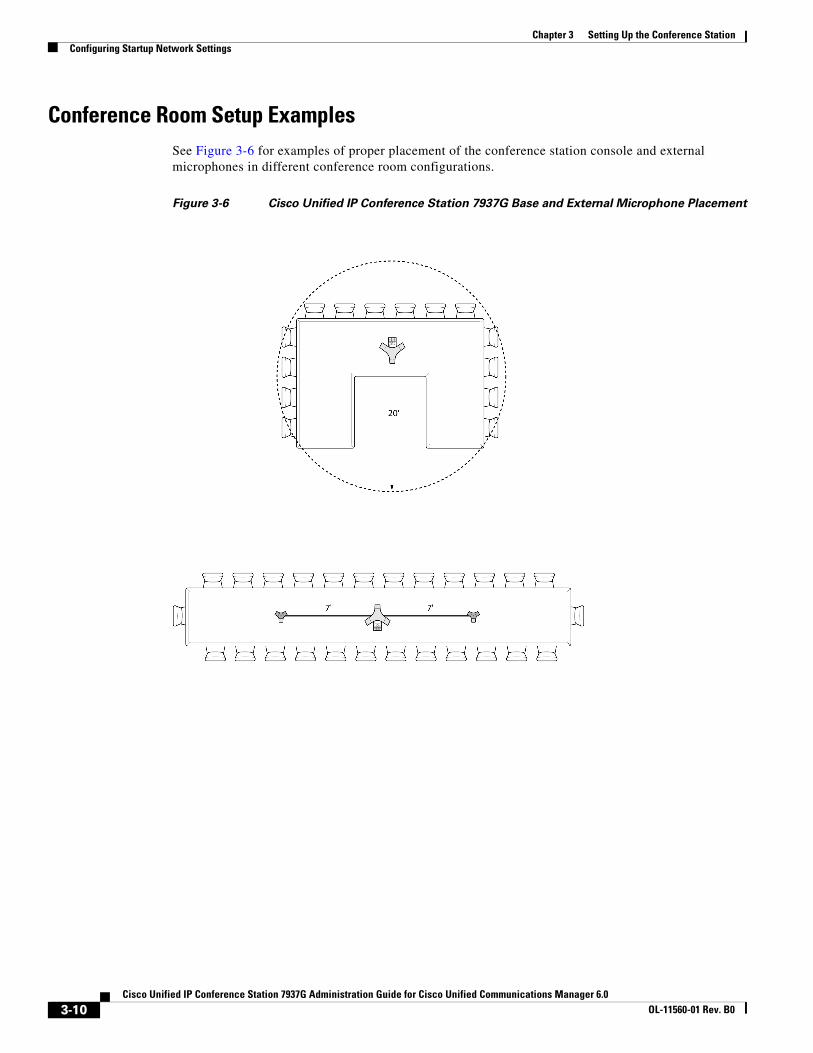
Chapter 3 Setting Up the Conference StationConfiguring Startup Network Settings
Conference Room Setup ExamplesSee Figure 3-6 for examples of proper placement of the conference station console and external microphones in different conference room configurations.
Figure 3-6 Cisco Unified IP Conference Station 7937G Base and External Microphone Placement
3-10Cisco Unified IP Conference Station 7937G Administration Guide for Cisco Unified Communications Manager 6.0
OL-11560-01 Rev. B0
Cisco Unified IP Conference Station 7937G Administration GuOL-11560-01 Rev. B0
C H A P T E R 4
Configuring Settings on the Conference StationThe Cisco Unified IP Conference Station 7937G includes many configurable network, device, and security settings that you may need to modify before the conference station is functional for your users. You can access these settings, and change many of them, through menus on the conference station.
This chapter includes the following topics:
• Configuration Menus on the Conference Station, page 4-1
• Overview of Options Configurable from a Conference Station, page 4-4
• Network Configuration Menu, page 4-5
• Device Configuration Menu, page 4-8
• Security Configuration Menu, page 4-12
Configuration Menus on the Conference StationThe conference station includes the following configuration menus:
• Network Configuration menu—Provides options for viewing and making a variety of network settings. For more information, see the “Network Configuration Menu” section on page 4-5.
• Device Configuration menu—Provides access to sub-menus from which you can view a variety of non network-related settings. For more information, see the “Device Configuration Menu” section on page 4-8.
• Security Configuration menu—Displays information about the current authentication security status of the conference station. For more information, see the “Security Configuration Menu” section on page 4-12.
Before you can change option settings on the Network and Security Configuration menus, you must unlock options for editing. See the “Unlocking and Locking Options” section on page 4-3 for instructions.
For information about the keys you can use to edit or change option settings, see the “Editing Values” section on page 4-3.
You can control whether a conference station user has access to conference station settings by using the Settings Access field on the Phone Configuration page in Cisco Unified Communications Manager Administration. For more information, see the “Displaying a Configuration Menu” section on page 4-2, or refer to Cisco Unified Communications Manager Administration Guide.
4-1ide for Cisco Unified Communications Manager 6.0
Chapter 4 Configuring Settings on the Conference StationConfiguration Menus on the Conference Station
Related Topics
• Unlocking and Locking Options, page 4-3
• Editing Values, page 4-3
• Overview of Options Configurable from a Conference Station, page 4-4
• Network Configuration Menu, page 4-5
• Device Configuration Menu, page 4-8
• Security Configuration Menu, page 4-12
Displaying a Configuration MenuTo display a configuration menu, perform the following steps:
Note You can control whether a conference station has access to the Settings menu or to options on this menu by using the Settings Access field in the Cisco Unified Communications Manager Administration Phone Configuration page. The Settings Access field accepts these values:
• Enabled—Allows access to the Settings menu.
• Disabled—Prevents access to the Settings menu.
• Restricted—Allows access to the User Preferences menu, but prevents access to other options on the Settings menu.
If you cannot access an option on the Settings menu, check the Settings Access field. For more information, refer to the Cisco Unified Communications Manager Administration Guide.
Procedure
Step 1 Choose Applications > Settings.
Step 2 Perform one of these actions to select an item in the Settings menu:
• Use the Navigation button to select the desired item, and then press Select.
• Use the keypad on the conference station to enter the number that corresponds to the item.
Step 3 To exit a menu, press the Exit softkey.
Related Topics
• Unlocking and Locking Options, page 4-3
• Editing Values, page 4-3
• Overview of Options Configurable from a Conference Station, page 4-4
• Network Configuration Menu, page 4-5
• Device Configuration Menu, page 4-8
• Security Configuration Menu, page 4-12
4-2Cisco Unified IP Conference Station 7937G Administration Guide for Cisco Unified Communications Manager 6.0
OL-11560-01 Rev. B0
Chapter 4 Configuring Settings on the Conference StationConfiguration Menus on the Conference Station
Unlocking and Locking OptionsConfiguration options that you can change from a conference station are locked by default to prevent users from making changes that could affect the operation of a conference station. You must unlock these options before you can change them.
When options are inaccessible for modification, a locked padlock icon appears on the configuration menus. When options are unlocked and accessible for modification, an unlocked padlock icon appears on these menus.
To unlock or lock options, press **#. This action either locks or unlocks the options, depending on the previous state.
Make sure to lock options after you have made your changes.
Caution Do not press **# to unlock options and then immediately press **# again to lock options. The conference station will interpret this sequence as **#**, which will reset the conference station. To lock options after unlocking them, wait at least 10 seconds before you press **# again.
Related Topics
• Displaying a Configuration Menu, page 4-2
• Editing Values, page 4-3
• Overview of Options Configurable from a Conference Station, page 4-4
• Network Configuration Menu, page 4-5
• Device Configuration Menu, page 4-8
• Security Configuration Menu, page 4-12
Editing ValuesWhen you edit the value of an option setting, follow these guidelines:
• Use the keys on the keypad to enter numbers and letters.
• To enter letters using the keypad, use a corresponding number key. Press the key one or more times to display a particular letter. For example, press the 2 key once for “a,” twice quickly for “b,” and three times quickly for “c.” After you pause, the cursor automatically advances to allow entry of the next letter.
• To enter a period (for example, in an IP address), press the . (period) softkey or press * on the keypad.
• Press << if you make a mistake. This softkey deletes the character to the left of the cursor.
• Press Cancel before pressing Save to discard any changes that you have made.
Note The conference station provides several methods to reset or restore option settings, if necessary. For more information, see the “Resetting or Restoring the Conference Station” section on page 9-11.
4-3Cisco Unified IP Conference Station 7937G Administration Guide for Cisco Unified Communications Manager 6.0
OL-11560-01 Rev. B0
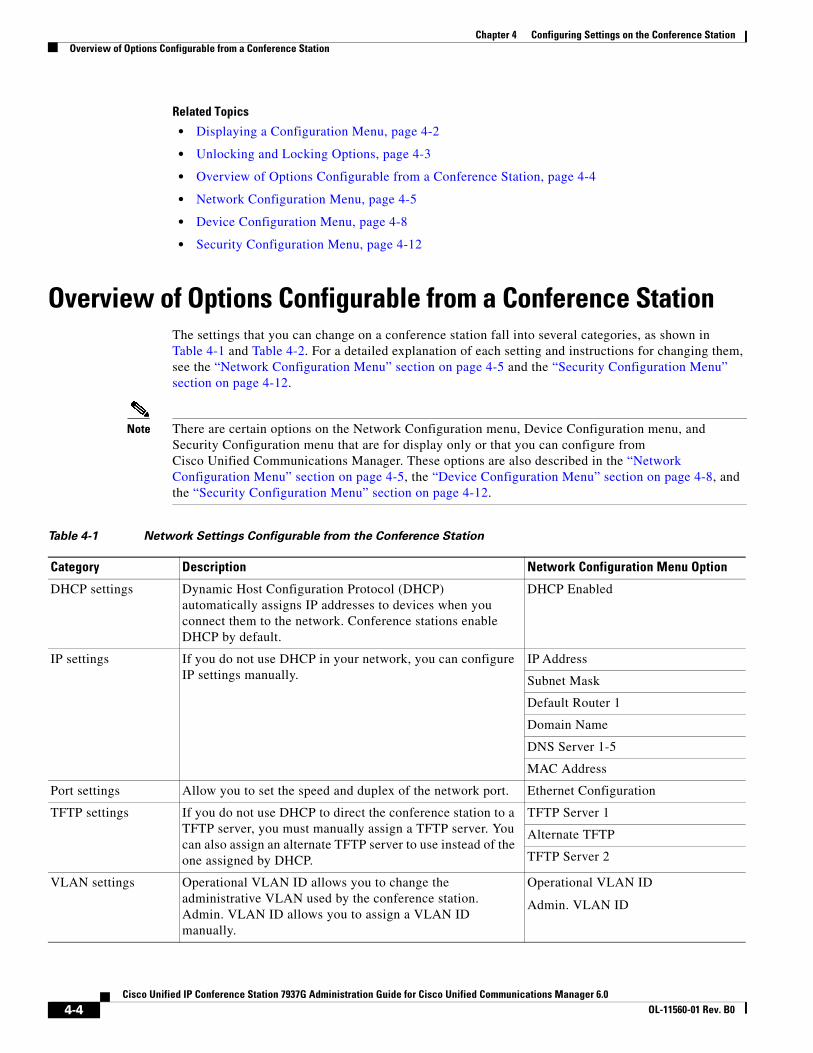
Chapter 4 Configuring Settings on the Conference StationOverview of Options Configurable from a Conference Station
Related Topics
• Displaying a Configuration Menu, page 4-2
• Unlocking and Locking Options, page 4-3
• Overview of Options Configurable from a Conference Station, page 4-4
• Network Configuration Menu, page 4-5
• Device Configuration Menu, page 4-8
• Security Configuration Menu, page 4-12
Overview of Options Configurable from a Conference StationThe settings that you can change on a conference station fall into several categories, as shown in Table 4-1 and Table 4-2. For a detailed explanation of each setting and instructions for changing them, see the “Network Configuration Menu” section on page 4-5 and the “Security Configuration Menu” section on page 4-12.
Note There are certain options on the Network Configuration menu, Device Configuration menu, and Security Configuration menu that are for display only or that you can configure from Cisco Unified Communications Manager. These options are also described in the “Network Configuration Menu” section on page 4-5, the “Device Configuration Menu” section on page 4-8, and the “Security Configuration Menu” section on page 4-12.
Table 4-1 Network Settings Configurable from the Conference Station
Category Description Network Configuration Menu Option
DHCP settings Dynamic Host Configuration Protocol (DHCP) automatically assigns IP addresses to devices when you connect them to the network. Conference stations enable DHCP by default.
DHCP Enabled
IP settings If you do not use DHCP in your network, you can configure IP settings manually.
IP Address
Subnet Mask
Default Router 1
Domain Name
DNS Server 1-5
MAC Address
Port settings Allow you to set the speed and duplex of the network port. Ethernet Configuration
TFTP settings If you do not use DHCP to direct the conference station to a TFTP server, you must manually assign a TFTP server. You can also assign an alternate TFTP server to use instead of the one assigned by DHCP.
TFTP Server 1
Alternate TFTP
TFTP Server 2
VLAN settings Operational VLAN ID allows you to change the administrative VLAN used by the conference station. Admin. VLAN ID allows you to assign a VLAN ID manually.
Operational VLAN ID
Admin. VLAN ID
4-4Cisco Unified IP Conference Station 7937G Administration Guide for Cisco Unified Communications Manager 6.0
OL-11560-01 Rev. B0

Chapter 4 Configuring Settings on the Conference StationNetwork Configuration Menu
Related Topics
• Displaying a Configuration Menu, page 4-2
• Unlocking and Locking Options, page 4-3
• Editing Values, page 4-3
• Network Configuration Menu, page 4-5
• Device Configuration Menu, page 4-8
• Security Configuration Menu, page 4-12
Network Configuration MenuThe Network Configuration menu provides options for viewing and configuring a variety of network settings. Table 4-3 describes these options and, where applicable, explains how to change them.
For information about how to access the Network Configuration menu, see the “Displaying a Configuration Menu” section on page 4-2.
Before you can change an option on this menu, you must unlock options. See the “Unlocking and Locking Options” section on page 4-3 for more information.
For information about the keys you can use to edit options, see the “Editing Values” section on page 4-3.
Table 4-2 Security Settings Configurable from the Conference Station
Category Description Security Configuration Menu Option
Security settings Allow you to enable 802.1X authentication
802.1X Authentication
Table 4-3 Network Configuration Menu Options
Option Description To Change
DHCP Enabled Indicates whether DHCP is being used by the conference station.
1. Unlock network configuration options. For more information, see the “Unlocking and Locking Options” section on page 4-3.
2. Choose Applications > Settings > Network Configuration > DHCP Enabled.
3. Select Enabled to enable DHCP or Disabled to disable DHCP.
4. Press Select, and then press Save.
IP Address Internet Protocol (IP) address of the conference station.
If you assign an IP address with this option, you must also assign a subnet mask and default router. See the Subnet Mask and Default Router options in this table.
1. Unlock network configuration options. For more information, see the “Unlocking and Locking Options” section on page 4-3.
2. Set the DHCP Enabled option to No. For more information, see the DHCP Enabled option in this table.
3. Choose Applications > Settings > Network Configuration > IP Address.
4. Enter a new IP Address.
5. Press Validate, and then press Save.
4-5Cisco Unified IP Conference Station 7937G Administration Guide for Cisco Unified Communications Manager 6.0
OL-11560-01 Rev. B0
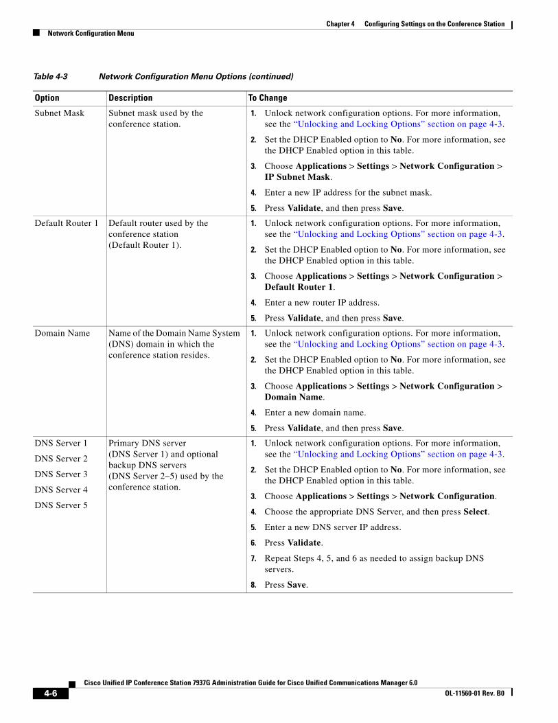
Chapter 4 Configuring Settings on the Conference StationNetwork Configuration Menu
Subnet Mask Subnet mask used by the conference station.
1. Unlock network configuration options. For more information, see the “Unlocking and Locking Options” section on page 4-3.
2. Set the DHCP Enabled option to No. For more information, see the DHCP Enabled option in this table.
3. Choose Applications > Settings > Network Configuration > IP Subnet Mask.
4. Enter a new IP address for the subnet mask.
5. Press Validate, and then press Save.
Default Router 1 Default router used by the conference station (Default Router 1).
1. Unlock network configuration options. For more information, see the “Unlocking and Locking Options” section on page 4-3.
2. Set the DHCP Enabled option to No. For more information, see the DHCP Enabled option in this table.
3. Choose Applications > Settings > Network Configuration > Default Router 1.
4. Enter a new router IP address.
5. Press Validate, and then press Save.
Domain Name Name of the Domain Name System (DNS) domain in which the conference station resides.
1. Unlock network configuration options. For more information, see the “Unlocking and Locking Options” section on page 4-3.
2. Set the DHCP Enabled option to No. For more information, see the DHCP Enabled option in this table.
3. Choose Applications > Settings > Network Configuration > Domain Name.
4. Enter a new domain name.
5. Press Validate, and then press Save.
DNS Server 1
DNS Server 2
DNS Server 3
DNS Server 4
DNS Server 5
Primary DNS server (DNS Server 1) and optional backup DNS servers (DNS Server 2–5) used by the conference station.
1. Unlock network configuration options. For more information, see the “Unlocking and Locking Options” section on page 4-3.
2. Set the DHCP Enabled option to No. For more information, see the DHCP Enabled option in this table.
3. Choose Applications > Settings > Network Configuration.
4. Choose the appropriate DNS Server, and then press Select.
5. Enter a new DNS server IP address.
6. Press Validate.
7. Repeat Steps 4, 5, and 6 as needed to assign backup DNS servers.
8. Press Save.
Table 4-3 Network Configuration Menu Options (continued)
Option Description To Change
4-6Cisco Unified IP Conference Station 7937G Administration Guide for Cisco Unified Communications Manager 6.0
OL-11560-01 Rev. B0
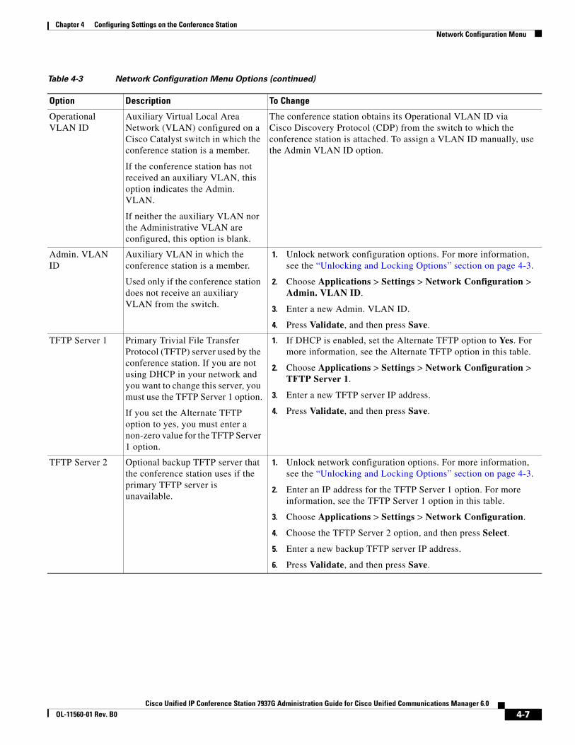
Chapter 4 Configuring Settings on the Conference StationNetwork Configuration Menu
Operational VLAN ID
Auxiliary Virtual Local Area Network (VLAN) configured on a Cisco Catalyst switch in which the conference station is a member.
If the conference station has not received an auxiliary VLAN, this option indicates the Admin. VLAN.
If neither the auxiliary VLAN nor the Administrative VLAN are configured, this option is blank.
The conference station obtains its Operational VLAN ID via Cisco Discovery Protocol (CDP) from the switch to which the conference station is attached. To assign a VLAN ID manually, use the Admin VLAN ID option.
Admin. VLAN ID
Auxiliary VLAN in which the conference station is a member.
Used only if the conference station does not receive an auxiliary VLAN from the switch.
1. Unlock network configuration options. For more information, see the “Unlocking and Locking Options” section on page 4-3.
2. Choose Applications > Settings > Network Configuration > Admin. VLAN ID.
3. Enter a new Admin. VLAN ID.
4. Press Validate, and then press Save.
TFTP Server 1 Primary Trivial File Transfer Protocol (TFTP) server used by the conference station. If you are not using DHCP in your network and you want to change this server, you must use the TFTP Server 1 option.
If you set the Alternate TFTP option to yes, you must enter a non-zero value for the TFTP Server 1 option.
1. If DHCP is enabled, set the Alternate TFTP option to Yes. For more information, see the Alternate TFTP option in this table.
2. Choose Applications > Settings > Network Configuration > TFTP Server 1.
3. Enter a new TFTP server IP address.
4. Press Validate, and then press Save.
TFTP Server 2 Optional backup TFTP server that the conference station uses if the primary TFTP server is unavailable.
1. Unlock network configuration options. For more information, see the “Unlocking and Locking Options” section on page 4-3.
2. Enter an IP address for the TFTP Server 1 option. For more information, see the TFTP Server 1 option in this table.
3. Choose Applications > Settings > Network Configuration.
4. Choose the TFTP Server 2 option, and then press Select.
5. Enter a new backup TFTP server IP address.
6. Press Validate, and then press Save.
Table 4-3 Network Configuration Menu Options (continued)
Option Description To Change
4-7Cisco Unified IP Conference Station 7937G Administration Guide for Cisco Unified Communications Manager 6.0
OL-11560-01 Rev. B0
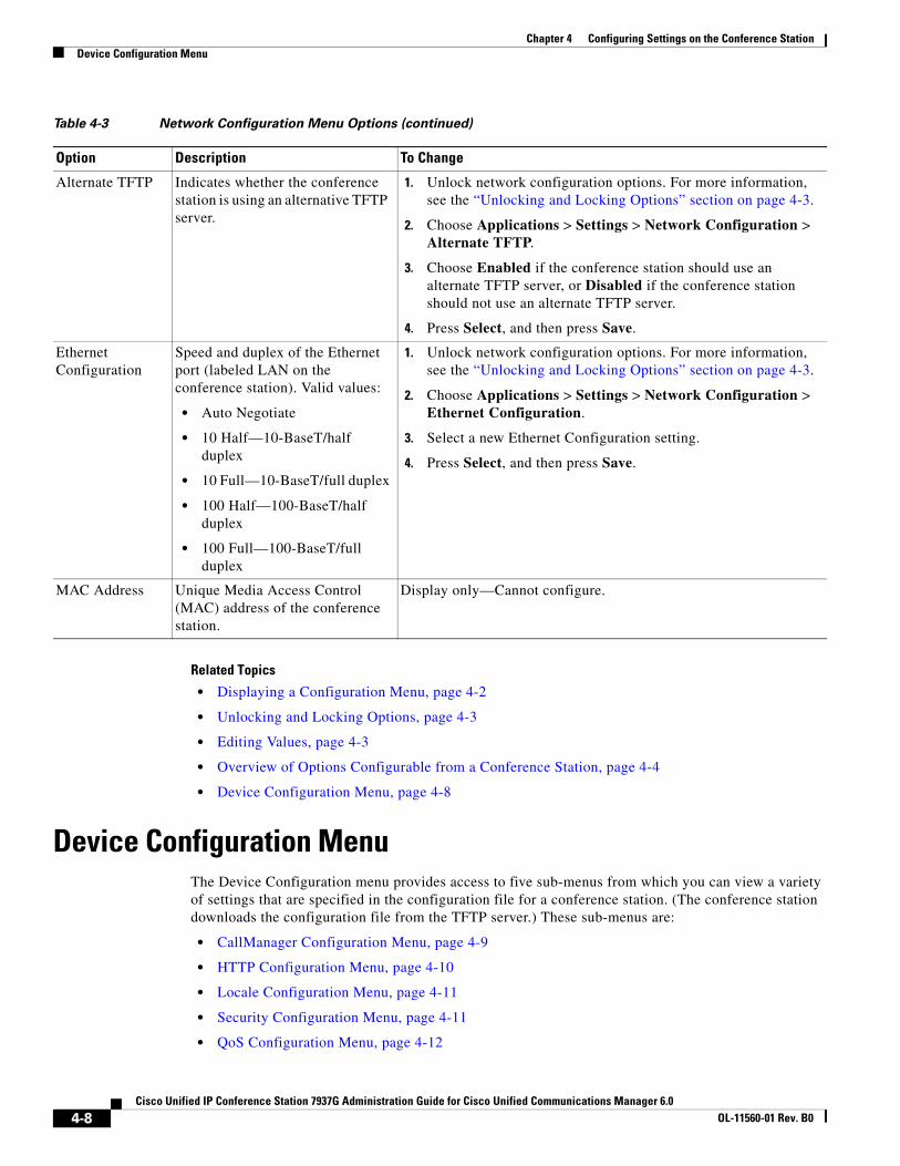
Chapter 4 Configuring Settings on the Conference StationDevice Configuration Menu
Related Topics
• Displaying a Configuration Menu, page 4-2
• Unlocking and Locking Options, page 4-3
• Editing Values, page 4-3
• Overview of Options Configurable from a Conference Station, page 4-4
• Device Configuration Menu, page 4-8
Device Configuration MenuThe Device Configuration menu provides access to five sub-menus from which you can view a variety of settings that are specified in the configuration file for a conference station. (The conference station downloads the configuration file from the TFTP server.) These sub-menus are:
• CallManager Configuration Menu, page 4-9
• HTTP Configuration Menu, page 4-10
• Locale Configuration Menu, page 4-11
• Security Configuration Menu, page 4-11
• QoS Configuration Menu, page 4-12
Alternate TFTP Indicates whether the conference station is using an alternative TFTP server.
1. Unlock network configuration options. For more information, see the “Unlocking and Locking Options” section on page 4-3.
2. Choose Applications > Settings > Network Configuration > Alternate TFTP.
3. Choose Enabled if the conference station should use an alternate TFTP server, or Disabled if the conference station should not use an alternate TFTP server.
4. Press Select, and then press Save.
Ethernet Configuration
Speed and duplex of the Ethernet port (labeled LAN on the conference station). Valid values:
• Auto Negotiate
• 10 Half—10-BaseT/half duplex
• 10 Full—10-BaseT/full duplex
• 100 Half—100-BaseT/half duplex
• 100 Full—100-BaseT/full duplex
1. Unlock network configuration options. For more information, see the “Unlocking and Locking Options” section on page 4-3.
2. Choose Applications > Settings > Network Configuration > Ethernet Configuration.
3. Select a new Ethernet Configuration setting.
4. Press Select, and then press Save.
MAC Address Unique Media Access Control (MAC) address of the conference station.
Display only—Cannot configure.
Table 4-3 Network Configuration Menu Options (continued)
Option Description To Change
4-8Cisco Unified IP Conference Station 7937G Administration Guide for Cisco Unified Communications Manager 6.0
OL-11560-01 Rev. B0
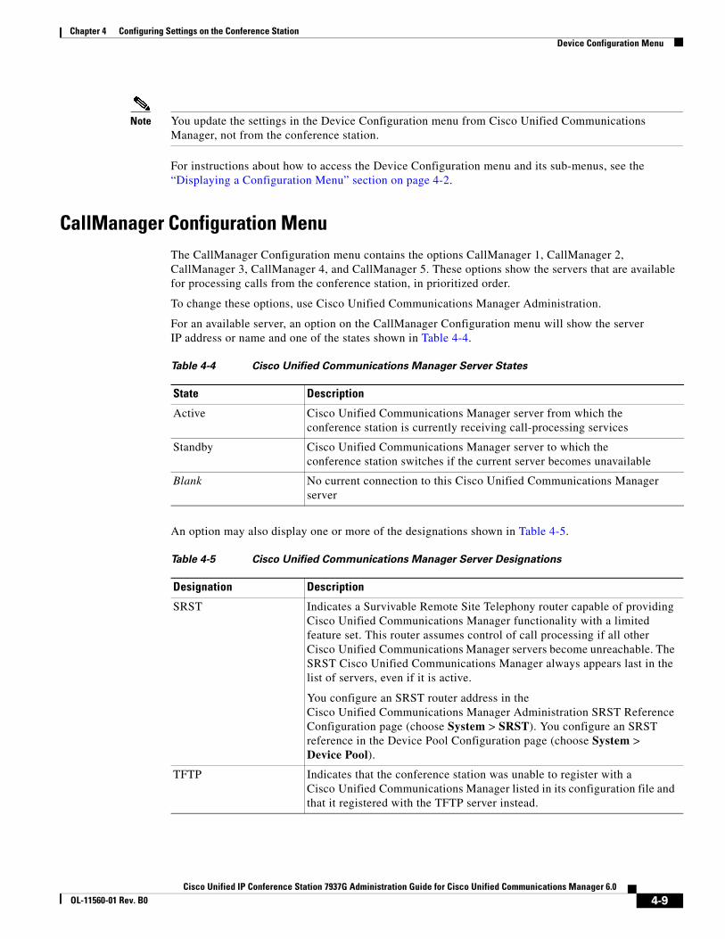
Chapter 4 Configuring Settings on the Conference StationDevice Configuration Menu
Note You update the settings in the Device Configuration menu from Cisco Unified Communications Manager, not from the conference station.
For instructions about how to access the Device Configuration menu and its sub-menus, see the “Displaying a Configuration Menu” section on page 4-2.
CallManager Configuration MenuThe CallManager Configuration menu contains the options CallManager 1, CallManager 2, CallManager 3, CallManager 4, and CallManager 5. These options show the servers that are available for processing calls from the conference station, in prioritized order.
To change these options, use Cisco Unified Communications Manager Administration.
For an available server, an option on the CallManager Configuration menu will show the server IP address or name and one of the states shown in Table 4-4.
An option may also display one or more of the designations shown in Table 4-5.
Table 4-4 Cisco Unified Communications Manager Server States
State Description
Active Cisco Unified Communications Manager server from which the conference station is currently receiving call-processing services
Standby Cisco Unified Communications Manager server to which the conference station switches if the current server becomes unavailable
Blank No current connection to this Cisco Unified Communications Manager server
Table 4-5 Cisco Unified Communications Manager Server Designations
Designation Description
SRST Indicates a Survivable Remote Site Telephony router capable of providing Cisco Unified Communications Manager functionality with a limited feature set. This router assumes control of call processing if all other Cisco Unified Communications Manager servers become unreachable. The SRST Cisco Unified Communications Manager always appears last in the list of servers, even if it is active.
You configure an SRST router address in the Cisco Unified Communications Manager Administration SRST Reference Configuration page (choose System > SRST). You configure an SRST reference in the Device Pool Configuration page (choose System > Device Pool).
TFTP Indicates that the conference station was unable to register with a Cisco Unified Communications Manager listed in its configuration file and that it registered with the TFTP server instead.
4-9Cisco Unified IP Conference Station 7937G Administration Guide for Cisco Unified Communications Manager 6.0
OL-11560-01 Rev. B0
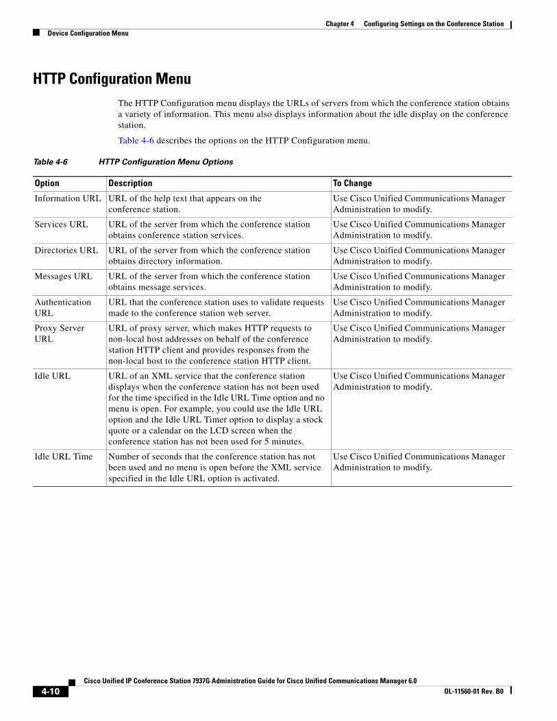
Chapter 4 Configuring Settings on the Conference StationDevice Configuration Menu
HTTP Configuration MenuThe HTTP Configuration menu displays the URLs of servers from which the conference station obtains a variety of information. This menu also displays information about the idle display on the conference station.
Table 4-6 describes the options on the HTTP Configuration menu.
Table 4-6 HTTP Configuration Menu Options
Option Description To Change
Information URL URL of the help text that appears on the conference station.
Use Cisco Unified Communications Manager Administration to modify.
Services URL URL of the server from which the conference station obtains conference station services.
Use Cisco Unified Communications Manager Administration to modify.
Directories URL URL of the server from which the conference station obtains directory information.
Use Cisco Unified Communications Manager Administration to modify.
Messages URL URL of the server from which the conference station obtains message services.
Use Cisco Unified Communications Manager Administration to modify.
Authentication URL
URL that the conference station uses to validate requests made to the conference station web server.
Use Cisco Unified Communications Manager Administration to modify.
Proxy Server URL
URL of proxy server, which makes HTTP requests to non-local host addresses on behalf of the conference station HTTP client and provides responses from the non-local host to the conference station HTTP client.
Use Cisco Unified Communications Manager Administration to modify.
Idle URL URL of an XML service that the conference station displays when the conference station has not been used for the time specified in the Idle URL Time option and no menu is open. For example, you could use the Idle URL option and the Idle URL Timer option to display a stock quote or a calendar on the LCD screen when the conference station has not been used for 5 minutes.
Use Cisco Unified Communications Manager Administration to modify.
Idle URL Time Number of seconds that the conference station has not been used and no menu is open before the XML service specified in the Idle URL option is activated.
Use Cisco Unified Communications Manager Administration to modify.
4-10Cisco Unified IP Conference Station 7937G Administration Guide for Cisco Unified Communications Manager 6.0
OL-11560-01 Rev. B0
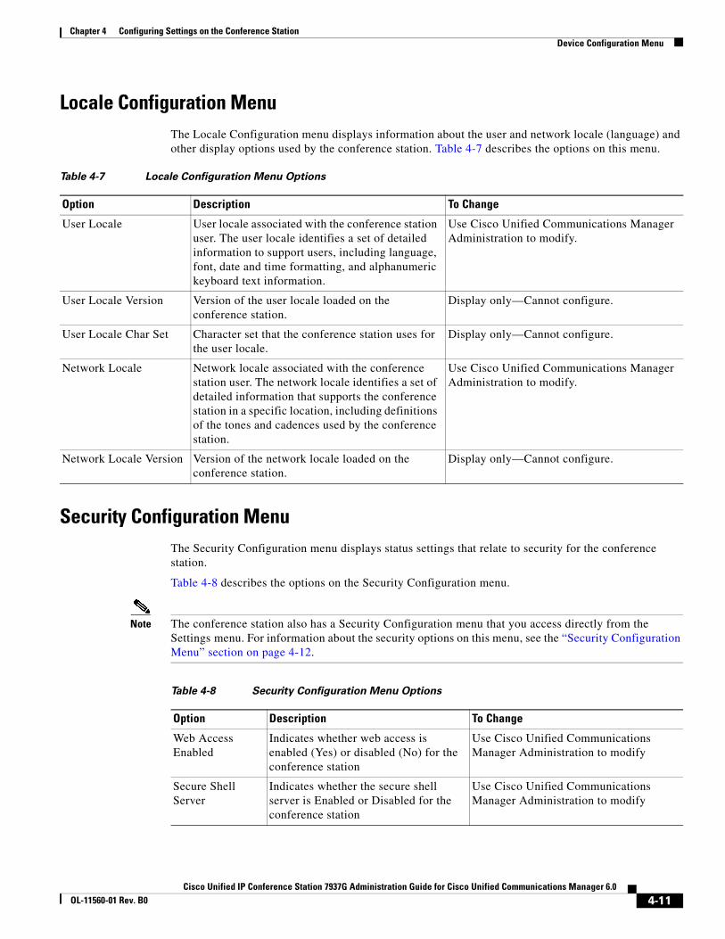
Chapter 4 Configuring Settings on the Conference StationDevice Configuration Menu
Locale Configuration MenuThe Locale Configuration menu displays information about the user and network locale (language) and other display options used by the conference station. Table 4-7 describes the options on this menu.
Security Configuration MenuThe Security Configuration menu displays status settings that relate to security for the conference station.
Table 4-8 describes the options on the Security Configuration menu.
Note The conference station also has a Security Configuration menu that you access directly from the Settings menu. For information about the security options on this menu, see the “Security Configuration Menu” section on page 4-12.
Table 4-7 Locale Configuration Menu Options
Option Description To Change
User Locale User locale associated with the conference station user. The user locale identifies a set of detailed information to support users, including language, font, date and time formatting, and alphanumeric keyboard text information.
Use Cisco Unified Communications Manager Administration to modify.
User Locale Version Version of the user locale loaded on the conference station.
Display only—Cannot configure.
User Locale Char Set Character set that the conference station uses for the user locale.
Display only—Cannot configure.
Network Locale Network locale associated with the conference station user. The network locale identifies a set of detailed information that supports the conference station in a specific location, including definitions of the tones and cadences used by the conference station.
Use Cisco Unified Communications Manager Administration to modify.
Network Locale Version Version of the network locale loaded on the conference station.
Display only—Cannot configure.
Table 4-8 Security Configuration Menu Options
Option Description To Change
Web Access Enabled
Indicates whether web access is enabled (Yes) or disabled (No) for the conference station
Use Cisco Unified Communications Manager Administration to modify
Secure Shell Server
Indicates whether the secure shell server is Enabled or Disabled for the conference station
Use Cisco Unified Communications Manager Administration to modify
4-11Cisco Unified IP Conference Station 7937G Administration Guide for Cisco Unified Communications Manager 6.0
OL-11560-01 Rev. B0
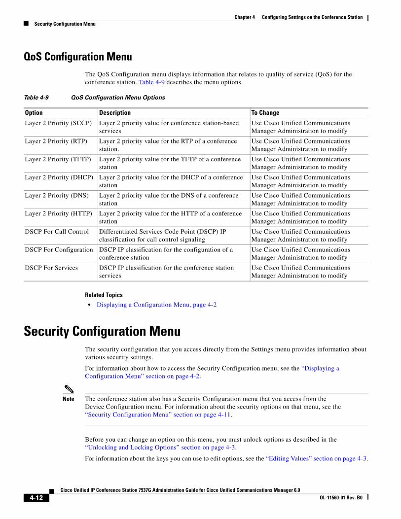
Chapter 4 Configuring Settings on the Conference StationSecurity Configuration Menu
QoS Configuration MenuThe QoS Configuration menu displays information that relates to quality of service (QoS) for the conference station. Table 4-9 describes the menu options.
Related Topics
• Displaying a Configuration Menu, page 4-2
Security Configuration MenuThe security configuration that you access directly from the Settings menu provides information about various security settings.
For information about how to access the Security Configuration menu, see the “Displaying a Configuration Menu” section on page 4-2.
Note The conference station also has a Security Configuration menu that you access from the Device Configuration menu. For information about the security options on that menu, see the “Security Configuration Menu” section on page 4-11.
Before you can change an option on this menu, you must unlock options as described in the “Unlocking and Locking Options” section on page 4-3.
For information about the keys you can use to edit options, see the “Editing Values” section on page 4-3.
Table 4-9 QoS Configuration Menu Options
Option Description To Change
Layer 2 Priority (SCCP) Layer 2 priority value for conference station-based services
Use Cisco Unified Communications Manager Administration to modify
Layer 2 Priority (RTP) Layer 2 priority value for the RTP of a conference station.
Use Cisco Unified Communications Manager Administration to modify
Layer 2 Priority (TFTP) Layer 2 priority value for the TFTP of a conference station
Use Cisco Unified Communications Manager Administration to modify
Layer 2 Priority (DHCP) Layer 2 priority value for the DHCP of a conference station
Use Cisco Unified Communications Manager Administration to modify
Layer 2 Priority (DNS) Layer 2 priority value for the DNS of a conference station
Use Cisco Unified Communications Manager Administration to modify
Layer 2 Priority (HTTP) Layer 2 priority value for the HTTP of a conference station
Use Cisco Unified Communications Manager Administration to modify
DSCP For Call Control Differentiated Services Code Point (DSCP) IP classification for call control signaling
Use Cisco Unified Communications Manager Administration to modify
DSCP For Configuration DSCP IP classification for the configuration of a conference station
Use Cisco Unified Communications Manager Administration to modify
DSCP For Services DSCP IP classification for the conference station services
Use Cisco Unified Communications Manager Administration to modify
4-12Cisco Unified IP Conference Station 7937G Administration Guide for Cisco Unified Communications Manager 6.0
OL-11560-01 Rev. B0

Chapter 4 Configuring Settings on the Conference StationSecurity Configuration Menu
Table 4-10 describes the options in the Security Configuration menu.
802.1X Authentication and StatusThe 802.1X Authentication and 802.1X Authentication Status options allow you to enable 802.1X authentication and monitor its progress. These options are described in Table 4-11 and Table 4-12.
Table 4-10 Security Configuration Menu Options
Option Description To Change
Shell Access Control
Allows users to enter a user name and password for secure shell access
Use Cisco Unified Communications Manager Administration Phone Configuration window to modify
802.1X Authentication
Allows you to enable 802.1X authentication for this conference station
See the “802.1X Authentication and Status” section on page 4-13
802.1X Authentication Status
Displays real-time status progress of the 802.1X authentication transaction
Display only—Cannot configure
Table 4-11 802.1X Authentication Setting
Option Description To Change
802.1X Authentication
Determines whether 802.1X authentication is enabled:
• Enabled—Conference station uses 802.1X authentication to request network access
• Disabled—Default setting in which the phone uses CDP to acquire VLAN and network access
1. Unlock network configuration options. For more information, see the “Unlocking and Locking Options” section on page 4-3.
2. Choose Applications > Settings > Security Configuration > 802.1X Authentication > Device Authentication.
3. Choose Enabled to request network access, or Disabled to use the default setting.
4. Press Select, and then press Save.
4-13Cisco Unified IP Conference Station 7937G Administration Guide for Cisco Unified Communications Manager 6.0
OL-11560-01 Rev. B0
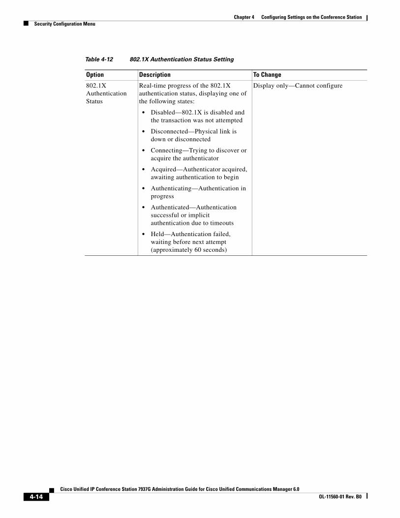
Chapter 4 Configuring Settings on the Conference StationSecurity Configuration Menu
Table 4-12 802.1X Authentication Status Setting
Option Description To Change
802.1X Authentication Status
Real-time progress of the 802.1X authentication status, displaying one of the following states:
• Disabled—802.1X is disabled and the transaction was not attempted
• Disconnected—Physical link is down or disconnected
• Connecting—Trying to discover or acquire the authenticator
• Acquired—Authenticator acquired, awaiting authentication to begin
• Authenticating—Authentication in progress
• Authenticated—Authentication successful or implicit authentication due to timeouts
• Held—Authentication failed, waiting before next attempt (approximately 60 seconds)
Display only—Cannot configure
4-14Cisco Unified IP Conference Station 7937G Administration Guide for Cisco Unified Communications Manager 6.0
OL-11560-01 Rev. B0
Cisco Unified IP Conference Station 7937G Administration GuOL-11560-01 Rev. B0
C H A P T E R 5
Configuring Features, Templates, Services, and UsersAfter you install conferences stations in your network, configure network settings, and add each Cisco Unified IP Conference Station 7937G to Cisco Unified Communications Manager, you must use the Cisco Unified Communications Manager Administration application to configure telephony features, optionally modify conference station templates, set up services, and assign users.
This chapter provides an overview of these configuration and setup procedures. Cisco Unified Communications Manager documentation provides detailed instructions for these procedures.
For suggestions about how to provide users with information about features, and what information to provide, see Appendix A, “Providing Information to Users Via a Website.”
For information about setting up conference stations in non-English environments, see Appendix B, “Supporting International Users.”
This chapter includes the following topics:
• Telephony Features Available for the Conference Station, page 5-1
• Configuring Corporate and Personal Directories, page 5-6
• Modifying Button Templates, page 5-7
• Configuring Softkey Templates, page 5-8
• Setting Up Services, page 5-8
• Adding Users to Cisco Unified Communications Manager, page 5-9
• Managing the User Options Web Pages, page 5-9
Telephony Features Available for the Conference StationAfter you add conference stations to Cisco Unified Communications Manager, you can add functionality to the conference stations. Table 5-1 includes a list of supported telephony features, many of which you can configure using Cisco Unified Communications Manager Administration. The Configuration Reference column lists Cisco Unified Communications Manager documentation that contains configuration procedures and related information.
For information about using most of these features on the conference station, refer to Cisco Unified IP Conference Station 7937G Phone Guide for Cisco Unified Communications Manager 6.0. For a comprehensive listing of features on the conference station, refer to Cisco Unified IP Phone Features A–Z.
5-1ide for Cisco Unified Communications Manager 6.0
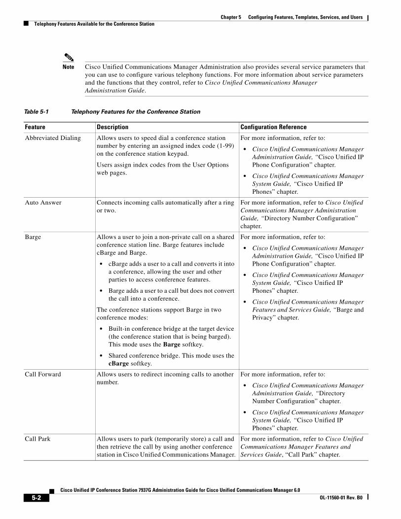
Chapter 5 Configuring Features, Templates, Services, and UsersTelephony Features Available for the Conference Station
Note Cisco Unified Communications Manager Administration also provides several service parameters that you can use to configure various telephony functions. For more information about service parameters and the functions that they control, refer to Cisco Unified Communications Manager Administration Guide.
Table 5-1 Telephony Features for the Conference Station
Feature Description Configuration Reference
Abbreviated Dialing Allows users to speed dial a conference station number by entering an assigned index code (1-99) on the conference station keypad.
Users assign index codes from the User Options web pages.
For more information, refer to:
• Cisco Unified Communications Manager Administration Guide, “Cisco Unified IP Phone Configuration” chapter.
• Cisco Unified Communications Manager System Guide, “Cisco Unified IP Phones” chapter.
Auto Answer Connects incoming calls automatically after a ring or two.
For more information, refer to Cisco Unified Communications Manager Administration Guide, “Directory Number Configuration” chapter.
Barge Allows a user to join a non-private call on a shared conference station line. Barge features include cBarge and Barge.
• cBarge adds a user to a call and converts it into a conference, allowing the user and other parties to access conference features.
• Barge adds a user to a call but does not convert the call into a conference.
The conference stations support Barge in two conference modes:
• Built-in conference bridge at the target device (the conference station that is being barged). This mode uses the Barge softkey.
• Shared conference bridge. This mode uses the cBarge softkey.
For more information, refer to:
• Cisco Unified Communications Manager Administration Guide, “Cisco Unified IP Phone Configuration” chapter.
• Cisco Unified Communications Manager System Guide, “Cisco Unified IP Phones” chapter.
• Cisco Unified Communications Manager Features and Services Guide, “Barge and Privacy” chapter.
Call Forward Allows users to redirect incoming calls to another number.
For more information, refer to:
• Cisco Unified Communications Manager Administration Guide, “Directory Number Configuration” chapter.
• Cisco Unified Communications Manager System Guide, “Cisco Unified IP Phones” chapter.
Call Park Allows users to park (temporarily store) a call and then retrieve the call by using another conference station in Cisco Unified Communications Manager.
For more information, refer to Cisco Unified Communications Manager Features and Services Guide, “Call Park” chapter.
5-2Cisco Unified IP Conference Station 7937G Administration Guide for Cisco Unified Communications Manager 6.0
OL-11560-01 Rev. B0

Chapter 5 Configuring Features, Templates, Services, and UsersTelephony Features Available for the Conference Station
Call Pickup Allows users to redirect a call that is ringing on another conference station within their pickup group to their conference station.
For more information, refer to Cisco Unified Communications Manager System Guide, “Call Pickup” chapter.
Call Waiting Indicates (and allows users to answer) an incoming call that rings while on another call. Displays incoming call information on the conference station screen.
For more information, refer to Cisco Unified Communications Manager System Guide, “Cisco Unified IP Phones” chapter.
Caller ID Displays caller identification such as a conference station or conference station number and/or a name on the conference station LCD screen.
For more information, refer to:
• Cisco Unified Communications Manager Administration Guide, “Configuring Cisco Unified IP Phones” chapter.
• Cisco Unified Communications Manager System Guide, “Understanding Route Plans” chapter.
• Cisco Unified Communications Manager Features and Services Guide, “Call Display Restrictions” chapter.
Cisco Call Back Provides users with an audio and visual alert on the conference station when a busy or unavailable party becomes available.
For more information, refer to:
• Cisco Unified Communications Manager System Guide, “Cisco Unified IP Phones” chapter.
• Cisco Unified Communications Manager Features and Services Guide, “Cisco Call Back” chapter.
Conference Allows a user to talk simultaneously with multiple parties by calling each participant individually. Conference features include Conference, Join, cBarge, and Meet-Me.
For more information, refer to Cisco Unified Communications Manager System Guide, “Conference Bridges” chapter.
Direct transfer Allows users to connect two calls to each other (without remaining on the line).
For more information, refer to Cisco Unified Communications Manager System Guide, “Cisco Unified IP Phones” chapter.
Extension Mobility Service
Allows a user temporarily to apply a conference station number and user profile settings to a shared conference station by logging into the Extension Mobility service on that conference station.
Extension Mobility can be useful if users work from a variety of locations within your company or if they share a workspace with coworkers.
For more information, refer to Cisco Unified Communications Manager Features and Services Guide, “Cisco Unified Communications Manager Extension Mobility” chapter.
Fast Dial Service Allows a user to enter a Fast Dial code to place a call. Fast Dial codes can be assigned to conference station numbers or Personal Address Book entries. (See “Services” in this table.)
For more information, refer to Cisco Unified IP Conference Station 7937G Phone Guide for Cisco Unified Communications Manager 6.0, “Advanced Call Handling” chapter.
Table 5-1 Telephony Features for the Conference Station (continued)
Feature Description Configuration Reference
5-3Cisco Unified IP Conference Station 7937G Administration Guide for Cisco Unified Communications Manager 6.0
OL-11560-01 Rev. B0

Chapter 5 Configuring Features, Templates, Services, and UsersTelephony Features Available for the Conference Station
Group call pickup Allows a user to answer a call ringing on a conference station in another group by using a group pickup code.
For more information, refer to Cisco Unified Communications Manager Features and Services Guide:
Hold Allows users to move connected calls from an active state to a held state.
Requires no configuration, unless you want to use music on hold; see “Music-on-hold” in this table for information.
Immediate Divert Allows users to transfer incoming calls directly to the voice messaging system.
For more information, refer to:
• Cisco Unified Communications Manager System Guide, “Cisco Unified IP Phones” chapter.
• Cisco Unified Communications Manager Features and Services Guide, “Immediate Divert” chapter.
Join Allows user to join two or more calls that are on one line to create a conference call and remain on the call.
For more information:
• See the “Configuring Softkey Templates” section on page 5-8.
• Refer to Cisco Unified Communications Manager System Guide, “Cisco Unified IP Phones” chapter.
Malicious caller identification (MCID)
Allows users to notify the system administrator about suspicious calls that are received.
For more information refer to:
• Cisco Unified Communications Manager System Guide, “Cisco Unified IP Phones” chapter.
• Cisco Unified Communications Manager Features and Services Guide, “Malicious Call Identification” chapter.
Meet-Me conference Allows a user to host a Meet-Me conference in which other participants call a predetermined number at a scheduled time.
For more information refer to:
• Cisco Unified Communications Manager Administration Guide, “Meet-Me Number/Pattern Configuration” chapter.
• Refer to Cisco Unified Communications Manager System Guide, “Conference Bridges” chapter.
Message waiting indicator
An icon on the LCD screen that indicates that a user has one or more new voice messages.
For more information refer to:
• Cisco Unified Communications Manager Administration Guide, “Message Waiting Configuration” chapter.
• Cisco Unified Communications Manager System Guide, “Voice Mail Connectivity to Cisco Unified Communications Manager” chapter.
Table 5-1 Telephony Features for the Conference Station (continued)
Feature Description Configuration Reference
5-4Cisco Unified IP Conference Station 7937G Administration Guide for Cisco Unified Communications Manager 6.0
OL-11560-01 Rev. B0
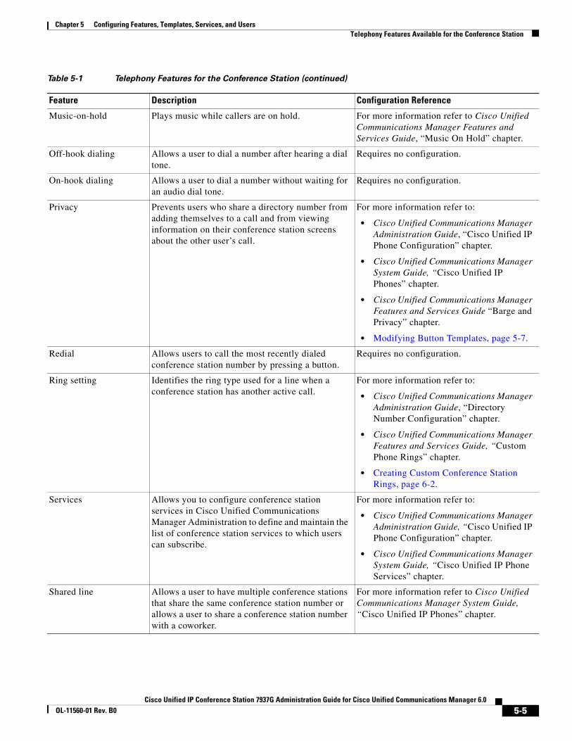
Chapter 5 Configuring Features, Templates, Services, and UsersTelephony Features Available for the Conference Station
Music-on-hold Plays music while callers are on hold. For more information refer to Cisco Unified Communications Manager Features and Services Guide, “Music On Hold” chapter.
Off-hook dialing Allows a user to dial a number after hearing a dial tone.
Requires no configuration.
On-hook dialing Allows a user to dial a number without waiting for an audio dial tone.
Requires no configuration.
Privacy Prevents users who share a directory number from adding themselves to a call and from viewing information on their conference station screens about the other user’s call.
For more information refer to:
• Cisco Unified Communications Manager Administration Guide, “Cisco Unified IP Phone Configuration” chapter.
• Cisco Unified Communications Manager System Guide, “Cisco Unified IP Phones” chapter.
• Cisco Unified Communications Manager Features and Services Guide “Barge and Privacy” chapter.
• Modifying Button Templates, page 5-7.
Redial Allows users to call the most recently dialed conference station number by pressing a button.
Requires no configuration.
Ring setting Identifies the ring type used for a line when a conference station has another active call.
For more information refer to:
• Cisco Unified Communications Manager Administration Guide, “Directory Number Configuration” chapter.
• Cisco Unified Communications Manager Features and Services Guide, “Custom Phone Rings” chapter.
• Creating Custom Conference Station Rings, page 6-2.
Services Allows you to configure conference station services in Cisco Unified Communications Manager Administration to define and maintain the list of conference station services to which users can subscribe.
For more information refer to:
• Cisco Unified Communications Manager Administration Guide, “Cisco Unified IP Phone Configuration” chapter.
• Cisco Unified Communications Manager System Guide, “Cisco Unified IP Phone Services” chapter.
Shared line Allows a user to have multiple conference stations that share the same conference station number or allows a user to share a conference station number with a coworker.
For more information refer to Cisco Unified Communications Manager System Guide, “Cisco Unified IP Phones” chapter.
Table 5-1 Telephony Features for the Conference Station (continued)
Feature Description Configuration Reference
5-5Cisco Unified IP Conference Station 7937G Administration Guide for Cisco Unified Communications Manager 6.0
OL-11560-01 Rev. B0
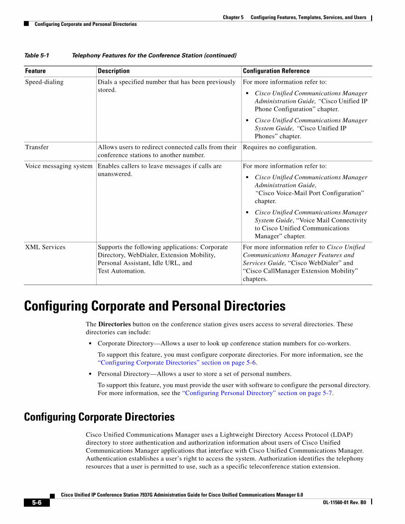
Chapter 5 Configuring Features, Templates, Services, and UsersConfiguring Corporate and Personal Directories
Configuring Corporate and Personal DirectoriesThe Directories button on the conference station gives users access to several directories. These directories can include:
• Corporate Directory—Allows a user to look up conference station numbers for co-workers.
To support this feature, you must configure corporate directories. For more information, see the “Configuring Corporate Directories” section on page 5-6.
• Personal Directory—Allows a user to store a set of personal numbers.
To support this feature, you must provide the user with software to configure the personal directory. For more information, see the “Configuring Personal Directory” section on page 5-7.
Configuring Corporate DirectoriesCisco Unified Communications Manager uses a Lightweight Directory Access Protocol (LDAP) directory to store authentication and authorization information about users of Cisco Unified Communications Manager applications that interface with Cisco Unified Communications Manager. Authentication establishes a user’s right to access the system. Authorization identifies the telephony resources that a user is permitted to use, such as a specific teleconference station extension.
Speed-dialing Dials a specified number that has been previously stored.
For more information refer to:
• Cisco Unified Communications Manager Administration Guide, “Cisco Unified IP Phone Configuration” chapter.
• Cisco Unified Communications Manager System Guide, “Cisco Unified IP Phones” chapter.
Transfer Allows users to redirect connected calls from their conference stations to another number.
Requires no configuration.
Voice messaging system Enables callers to leave messages if calls are unanswered.
For more information refer to:
• Cisco Unified Communications Manager Administration Guide, “Cisco Voice-Mail Port Configuration” chapter.
• Cisco Unified Communications Manager System Guide, “Voice Mail Connectivity to Cisco Unified Communications Manager” chapter.
XML Services Supports the following applications: Corporate Directory, WebDialer, Extension Mobility, Personal Assistant, Idle URL, and Test Automation.
For more information refer to Cisco Unified Communications Manager Features and Services Guide, “Cisco WebDialer” and “Cisco CallManager Extension Mobility” chapters.
Table 5-1 Telephony Features for the Conference Station (continued)
Feature Description Configuration Reference
5-6Cisco Unified IP Conference Station 7937G Administration Guide for Cisco Unified Communications Manager 6.0
OL-11560-01 Rev. B0
Chapter 5 Configuring Features, Templates, Services, and UsersModifying Button Templates
To install and set up these features, refer to Installing and Configuring the Cisco Customer Directory Configuration Plugin. This document guides you through the configuration process for integrating Cisco Unified Communications Manager with Microsoft Active Directory and Netscape Directory Server.
After the LDAP directory configuration completes, users can access the Corporate Directory service on the conference station to find users in the corporate directory.
Configuring Personal DirectoryPersonal Directory consists of the following features:
• Personal Address Book (PAB)
• Personal Fast Dials (Fast Dials)
• Address Book Synchronization Tool (TABSynch)
Users can access Personal Directory features by these methods:
• From a web browser—Users can access the PAB and Fast Dials features from the User Options web pages.
• From the conference station—Users can choose Directories > Personal Directory to access the PAB and Fast Dials features from their conference stations.
• From a Microsoft Windows application—Users can use the TABSynch tool to synchronize their PABs with Microsoft Outlook.
To configure Personal Directory from a web browser, users must access their User Options web pages. You must provide users with a URL and login information.
To synchronize with Microsoft Outlook, users must install the TABSynch utility, provided by you. To obtain the TABSynch software to distribute to users, log on to Cisco Unified Communications Manager Administration and choose Application > Plugins. Then, locate and click Cisco IP Phone Address Book Synchronizer. For detailed instructions on how to synchronize a PAB with Microsoft Outlook, see the “Installing and Configuring the Cisco Unified Communications Manager Address Book Synchronizer” section on page A-3.
Modifying Button TemplatesUsing Cisco Unified Communications Manager Administration, you can assign button templates to conference stations. Cisco Unified Communications Manager contains the Standard 7937 button template for the Cisco Unified IP Conference Station 7937G. This button template contains no configurable features. When you assign the Standard 7937 button template to a conference station, no buttons are added.
You can add a custom button template for the conference station that contains the Privacy feature. The Privacy feature allows a user to allow or disallow other users of shared-line devices to view call information or barge calls. When you assign a button template with Privacy to a conference station, users can access a Privacy softkey on the conference station that they can toggle on or off during a call.To add a button template, log on to Cisco Unified Communications Manager Administration and choose Device > Device Settings > Phone Button Template, and then press Add New. To assign a button template to a conference station, choose Device > Phone to select the conference station. In the Phone Configuration window, select a button template from the Phone Button Template drop-down list.
For more information on button templates, refer to Cisco Unified Communications Manager Administration Guide and Cisco Unified Communications Manager System Guide.
5-7Cisco Unified IP Conference Station 7937G Administration Guide for Cisco Unified Communications Manager 6.0
OL-11560-01 Rev. B0
Chapter 5 Configuring Features, Templates, Services, and UsersConfiguring Softkey Templates
Configuring Softkey TemplatesUsing Cisco Unified Communications Manager Administration, you can manage softkeys associated with applications that are supported by the conference station. Cisco Unified Communications Manager supports two types of softkey templates: standard and nonstandard. Standard softkey templates include Standard Assistant, Standard Manager, and Standard Shared Mode Manager. An application that supports softkeys can have one or more standard softkey templates associated with it. You can modify a standard softkey template by making a copy of it, giving it a new name, and making updates to that copied softkey template. You can also modify a nonstandard softkey template.
To configure softkey templates, log on to Cisco Unified Communications Manager Administration and choose Device > Device Settings > Softkey Template. To assign a softkey template to a conference station, choose Device > Phone to select the conference station. In the Phone Configuration window, select a softkey template from the Softkey Template drop-down list.
For more information on configuring and assigning softkey templates, refer to Cisco Unified Communications Manager Administration Guide and Cisco Unified Communications Manager System Guide.
Setting Up ServicesThe Applications button on the conference station gives users access to conference station services. These services comprise XML applications that enable the display of interactive content with text and graphics on the conference station. Examples of services include local movie times, stock quotes, and weather reports.
Before a user can access any service:
• You must use Cisco Unified Communications Manager Administration to configure available services.
• The user must subscribe to services using the User Options web pages. This web-based application provides a graphical user interface (GUI) for limited, end-user configuration of conference station applications.
Before you set up services, gather the URLs for the sites you want to set up and verify that users can access those sites from your corporate IP telephony network.
To set up these services, log on to Cisco Unified Communications Manager Administration and choose Device > Device Settings > Phone Services. Refer to Cisco Unified Communications Manager Administration Guide and to Cisco Unified Communications Manager System Guide for more information.
After you configure these services, verify that your users have access to the User Options web pages, from which they can select and subscribe to configured services. See the “How Users Subscribe to Services and Configure Conference Station Features” section on page A-2 for a summary of the information that you must provide to end users.
5-8Cisco Unified IP Conference Station 7937G Administration Guide for Cisco Unified Communications Manager 6.0
OL-11560-01 Rev. B0

Chapter 5 Configuring Features, Templates, Services, and UsersAdding Users to Cisco Unified Communications Manager
Adding Users to Cisco Unified Communications ManagerAdding users to Cisco Unified Communications Manager allows you to display and maintain information about users and allows each user to perform these tasks:
• Access the corporate directory and other customized directories from a conference station
• Create a personal directory
• Set up speed dial and call forwarding numbers
• Subscribe to services that are accessible from a conference station
You can add users to Cisco Unified Communications Manager using either of these methods:
• To add users individually, log on to Cisco Unified Communications Manager Administration and choose User Management > End User. To add users to user groups, choose User Management > User Group.
For more information about adding users, refer to Cisco Unified Communications Manager Administration Guide. For details about user information, refer to Cisco Unified Communications Manager System Guide.
• To add users in batches, use the Bulk Administration Tool. This method also enables you to set an identical default password for all users.
For information about the Bulk Administration Tool, refer to Cisco Unified Communications Manager Bulk Administration Guide.
Managing the User Options Web PagesFrom the User Options web page, users can customize and control several conference station features and settings. For detailed information about the User Options web pages, refer to Cisco Unified IP Conference Station 7937G Phone Guide for Cisco Unified Communications Manager 6.0.
Giving Users Access to the User Options Web PagesBefore a user can access the User Options web pages, you must use Cisco Unified Communications Manager Administration to configure the user as an End User. You must also associate appropriate conference stations with the user, and add the user to a user group. To select and configure an end user, log on to Cisco Unified Communications Manager Administration and choose User Management > End User. To add a user to a user group, choose User Management > User Group.
For additional information, refer to Cisco Unified Communications Manager Administration Guide, “End User Configuration” section.
Specifying Options that Appear on the User Options Web PagesMost options on the User Options web pages appear by default. However, two options that do not appear by default are:
• Ring Settings
• Line Text Label Settings
5-9Cisco Unified IP Conference Station 7937G Administration Guide for Cisco Unified Communications Manager 6.0
OL-11560-01 Rev. B0

Chapter 5 Configuring Features, Templates, Services, and UsersManaging the User Options Web Pages
You can control the options that appear on the User Options web pages by using enterprise parameter settings in Cisco Unified Communications Manager Administration.
Note The settings apply to all User Options web pages at your site.
To specify the options that appear on the User Options web pages, follow these steps:
Procedure
Step 1 From Cisco Unified Communications Manager Administration, choose System > Enterprise Parameters.
The Enterprise Parameters Configuration page appears.
Step 2 In the CCMUser Parameters area, specify whether a parameter appears on the User Options web pages by choosing one of these values from the drop-down list for a parameter:
True—Option appears on the User Options web pages (default).
False—Option does not appear on the User Options web pages.
5-10Cisco Unified IP Conference Station 7937G Administration Guide for Cisco Unified Communications Manager 6.0
OL-11560-01 Rev. B0
Cisco Unified IP Conference Station 7937G Administration GuOL-11560-01 Rev. B0
C H A P T E R 6
Customizing the Conference StationThis chapter explains how you customize configuration files, Cisco Unified IP Conference Station 7937G ring sounds, and the idle display at your site. Ring sounds play when the conference station receives a call. The idle display appears on the LCD screen when the conference station has not been used for a designated period.
This chapter includes these topics:
• Customizing and Modifying Configuration Files, page 6-1
• Creating Custom Conference Station Rings, page 6-2
• Configuring the Idle Display, page 6-4
Customizing and Modifying Configuration FilesYou can modify configuration files (for example, edit the xml files) and add customized files (for example, custom ring tones and call back tones) to the Trivial File Transfer Protocol (TFTP) directory. You can modify files and add customized files to the TFTP directory in Cisco IPT Platform Administration from the TFTP Server File Upload page. Refer to Cisco Unified Communications Operating System Administration Guide for information about how to upload files to the TFTP folder in Cisco Unified Communications Manager.
You can obtain a copy of the Ringlist.xml and List.xml files from the system using the following admin command-line interface (CLI) “file” commands:
• admin:file
– file list*
– file view*
– file search*
– file get*
– file dump*
– file tail*
– file delete*
6-1ide for Cisco Unified Communications Manager 6.0
Chapter 6 Customizing the Conference StationCreating Custom Conference Station Rings
Creating Custom Conference Station RingsThe conference station ships with two default ring types that are implemented in hardware: Chirp1 and Chirp2. Cisco Unified Communications Manager also provides a default set of additional conference station ring sounds that are implemented in software as pulse code modulation (PCM) files. The PCM files, along with an XML file (named Ringlist.xml) that describes the ring list options that are available at your site, exist in the TFTP directory on each Cisco Unified Communications Manager.
For more information, refer to Cisco Unified Communications Manager System Guide, Release 5.1(1), “Cisco TFTP” chapter, and Cisco Unified Communications Operating System Administration Guide, “Software Upgrades” chapter.
The following sections describe how you can customize the conference station rings that are available at your site by creating PCM files and editing the Ringlist.xml file:
• Ringlist.xml File Format Requirements, page 6-2
• PCM File Requirements for Custom Ring Types, page 6-3
• Configuring a Custom Conference Station Ring, page 6-3
Ringlist.xml File Format RequirementsThe Ringlist.xml file defines an XML object that contains a list of conference station ring types. This file can include up to 50 ring types. Each ring type contains a pointer to the PCM file that is used for that ring type and the text that will appear on the Ring Type menu on a conference station for that ring. The Cisco TFTP server for each Cisco Unified Communications Manager contains this file.
The CiscoIPconference stationRingList XML object uses the following simple tag set to describe the information:
<CiscoIPconference stationRingList> <Ring> <DisplayName/> <FileName/> </Ring></CiscoIPconference stationRingList>
The following characteristics apply to the definition names. You must include the required DisplayName and FileName for each conference station ring type.
• DisplayName defines the name of the custom ring for the associated PCM file that will display on the Ring Type menu of the conference station.
• FileName specifies the name of the PCM file for the custom ring to associate with DisplayName.
Note The DisplayName and FileName fields must not exceed 25 characters.
This example shows a Ringlist.xml file that defines two conference station ring types:
<CiscoIPconference stationRingList> <Ring> <DisplayName>Analog Synth 1</DisplayName> <FileName>Analog1.raw</FileName> </Ring> <Ring> <DisplayName>Analog Synth 2</DisplayName> <FileName>Analog2.raw</FileName> </Ring></CiscoIPconference stationRingList>
6-2Cisco Unified IP Conference Station 7937G Administration Guide for Cisco Unified Communications Manager 6.0
OL-11560-01 Rev. B0
Chapter 6 Customizing the Conference StationCreating Custom Conference Station Rings
PCM File Requirements for Custom Ring Types The PCM files for the ring types must meet the following requirements for proper playback on conference stations:
• Raw PCM (no header)
• 8000 samples per second
• 8 bits per sample
• uLaw compression
• Maximum ring size is 16080 samples
• Minimum ring size is 240 samples
• Number of samples in the ring is evenly divisible by 240.
• Ring starts and ends at the zero crossing
• To create PCM files for custom conference station rings, you can use any standard audio editing packages that support these file format requirements
Configuring a Custom Conference Station RingTo create custom conference station rings for the conference station, follow these steps:
Procedure
Step 1 Create a PCM file for each custom ring (one ring per file). Ensure the PCM files comply with the format guidelines that are listed in the “PCM File Requirements for Custom Ring Types” section on page 6-3.
Step 2 Upload the new PCM files that you created to the Cisco TFTP server for each Cisco Unified Communications Manager in your cluster. For more information, refer to Cisco Unified Communications Operating System Administration Guide, “Software Upgrades” chapter.
Step 3 Use a text editor to edit the Ringlist.xml file. See the “Ringlist.xml File Format Requirements” section on page 6-2 for information about how to format this file and for a sample Ringlist.xml file.
Step 4 Save your modifications and close the Ringlist.xml file.
Step 5 Cache the new Ringlist.xml file:
a. Log on to Cisco Unified Communications Manager Administration.
b. From the Navigation drop-down list at the top right of the window, select Cisco Unified Serviceability, and then press Go.
c. Choose Tools > Control Center - Feature Services.
d. In the CM Services area, locate, stop, and start the Cisco TFTP service.
6-3Cisco Unified IP Conference Station 7937G Administration Guide for Cisco Unified Communications Manager 6.0
OL-11560-01 Rev. B0
Chapter 6 Customizing the Conference StationConfiguring the Idle Display
Configuring the Idle DisplayYou can specify an idle display that appears on the conference station LCD screen. The idle display is an XML service that the conference station invokes when the conference station has been idle (not in use) for a designated period and no feature menu is open.
XML services that can be used as idle displays include company logos, product pictures, and stock quotes.
Configuring the idle display consists of these general steps:
1. Formatting an image for display on the conference station.
2. Configuring Cisco Unified Communications Manager to display the image on the conference station.
For detailed instructions about creating and displaying the idle display, refer to Creating Idle URL Using Graphics on Cisco IP Phone at this URL:
http://www.cisco.com/warp/public/788/AVVID/idle-url.html
In addition, you can refer to Cisco Unified Communications Manager Administration Guide or to Cisco Unified Communications Manager Bulk Administration Guide for the following information:
• Specifying the URL of the idle display XML service:
– For a single conference station—Idle field on the Phone Template Configuration page in the Bulk Administration Tool (BAT)
– For multiple conference stations simultaneously—URL Idle Time field on the Cisco Unified Communications Manager Enterprise Parameters page, or the Idle field in the Bulk Administration Tool (BAT)
• Specifying the length of time that the conference station is not used before the idle display XML service is invoked:
– For a single conference station—Idle Timer field on the Cisco Unified Communications Manager Administration Phone Configuration page
– For multiple conference stations simultaneously—URL Idle Time field on the Cisco Unified Communications Manager Administration Enterprise Parameters Configuration page, or the Idle Timer field in the Bulk Administration Tool (BAT)
From a conference station, you can see settings for the idle display XML service URL and the length of time that the conference station is not used before this service is invoked. To see these settings, choose Applications > Settings > Device Configuration > HTTP Configuration, and then scroll to the Idle URL and the Idle URL Time parameters.
6-4Cisco Unified IP Conference Station 7937G Administration Guide for Cisco Unified Communications Manager 6.0
OL-11560-01 Rev. B0
Cisco Unified IP Conference Station 7937G Administration GuOL-11560-01 Rev. B0
C H A P T E R 7
Viewing Model Information, Status, and Statistics on the Conference StationThis chapter describes how to use the following menus and screens on the Cisco Unified IP Conference Station 7937G to view conference station information such as model, device, and network information:
• Model Information screen—Displays hardware and software information about the conference station.
• Status menu—Provides access to screens that display network and call statistics and device information.
You can use the information on these screens to monitor the operation of a conference station and to assist with troubleshooting.
You can also obtain much of this information, and obtain other related information, remotely through the conference station’s web page. For more information, see Chapter 8, “Monitoring the Conference Station Remotely.”
For more information about troubleshooting the conference station, see Chapter 9, “Troubleshooting and Maintenance.”
Note There are certain options on the Network Configuration menu, Device Configuration menu, and Security Configuration menu that are for display only. These options are described in the “Network Configuration Menu” section on page 4-5, the “Device Configuration Menu” section on page 4-8, and the “Security Configuration Menu” section on page 4-12.
This chapter includes these topics:
• Model Information Screen, page 7-1
• Status Menu, page 7-2
Model Information ScreenThe Model Information screen displays this information:
• Model Number—Model number of the conference station.
• MAC Address—Media Access Control (MAC) address of the conference station.
• Software Version—Version of the firmware running on the conference station.
7-1ide for Cisco Unified Communications Manager 6.0
Chapter 7 Viewing Model Information, Status, and Statistics on the Conference StationStatus Menu
• BootROM Version—Identifier of the factory-installed load running on the conference station.
• App Load ID—Identifies the firmware running on the conference station.
To display the Model Information screen, choose Applications > Settings > Model Information. To exit the Model Information screen, press Exit.
Status MenuThe Status menu includes these options, which provide information about the conference station and its operation:
• Network Statistics—Displays the Network Statistics screen, which shows Ethernet traffic statistics. For more information, see the “Network Statistics Screen” section on page 7-2.
• Call Statistics—Displays information about the last call on the conference station. For more information, see the “Call Statistics Screen” section on page 7-4.
• Device Information—Displays device settings and related information for the conference station. For more information, see the “Device Information Screen” section on page 7-5.
Note The Status menu also contains a Ping menu that allows you to test network connectivity to another conference station. For more information, see the “Using Ping” section on page 9-2
To display the Status menu, choose Applications > Settings > Status. To exit the Status menu, press Exit.
Network Statistics ScreenThe Network Statistics screen displays information about the conference station and network performance. Table 7-1 describes the information that appears in this screen.
To display the Network Statistics screen, choose Applications > Settings > Status > Network Statistics.
To reset the Rx Frames, Tx Frames, and Rx Broadcasts statistics to 0, press Clear. To exit the Network Statistics screen, press Exit.
Table 7-1 Network Statistics Items
Item Description
Rx Frames Number of packets received by the conference station.
Tx Frames Number of packets transmitted by the conference station.
Rx error Total number of FCS error packets or Align error packets received.
Rx PacketNoDes Total number of shed packets caused by no DMA descriptor.
Rx Overruns Total number of received packets dropped because of buffer overruns.
Rx alignErr Total number of packets received between 64 and 1522 bytes in length that have bad FCS errors.
Rx length error Number of packets discorded due to improper length.
7-2Cisco Unified IP Conference Station 7937G Administration Guide for Cisco Unified Communications Manager 6.0
OL-11560-01 Rev. B0
Chapter 7 Viewing Model Information, Status, and Statistics on the Conference StationStatus Menu
Rx symbol error Number of valid length packets received that have at least one invalid data symbol.
Rx CRC Errors Total number of packets received with CRC failed.
Rx Broadcasts Number of broadcast packets received by the conference station.
Rx Multicasts Total number of multicast packets received by the conference station.
Rx fail filter Total number of packets received by the conference station that failed.
Rx VLAN Total number of packets received on the Virtual Local Area Network.
Rx control frames Total number of control frames received.
Rx unicast Total number of unicast packets received by the conference station.
Tx error Total number of FCS error packets or Align error packets transmitted by the conference station.
Tx no descriptor Total number of transmit packets dropped because no descriptor was specified.
Tx fifoUnderrun Total number of transmit packets dropped because of fifo underrun.
Tx lateCollision Number of times that collisions occurred later than 512 bit times after the start of packet transmission.
Tx Excessive Collisions Total number of packets that could not be sent because of network congestion.
Tx excessDefer Total number of packets delayed from transmitting due to medium being busy.
Tx Deferred Abort Total number of transmit packets aborted.
Tx Collisions Total number of collisions that occurred while a packet was being transmitted.
Event send failed Total number of packets that failed to transmit.
Event Rx packet send failed
Total number of packets that were not received.
Tx excessLength Total number of packets not transmitted because the packet experienced 16 transmission attempts.
Rx totalPkt Total number of packets received by the conference station.
Packet Transmitted Total number of packets transmitted by the conference station.
Rcvr Octets Total number of RTP data packets received by the conference station since starting receiving data on this connection. Includes packets received from different sources if this is a multicast call. The value displays as 0 if the connection was set to send-only mode.
Sender Octets Total number of payload octets transmitted in RTP data packets by the conference station since starting this connection. The value is 0 if the connection is set to receive-only mode.
Table 7-1 Network Statistics Items (continued)
Item Description
7-3Cisco Unified IP Conference Station 7937G Administration Guide for Cisco Unified Communications Manager 6.0
OL-11560-01 Rev. B0
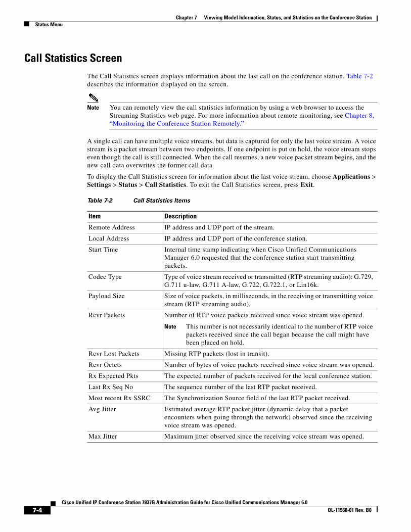
Chapter 7 Viewing Model Information, Status, and Statistics on the Conference StationStatus Menu
Call Statistics ScreenThe Call Statistics screen displays information about the last call on the conference station. Table 7-2 describes the information displayed on the screen.
Note You can remotely view the call statistics information by using a web browser to access the Streaming Statistics web page. For more information about remote monitoring, see Chapter 8, “Monitoring the Conference Station Remotely.”
A single call can have multiple voice streams, but data is captured for only the last voice stream. A voice stream is a packet stream between two endpoints. If one endpoint is put on hold, the voice stream stops even though the call is still connected. When the call resumes, a new voice packet stream begins, and the new call data overwrites the former call data.
To display the Call Statistics screen for information about the last voice stream, choose Applications > Settings > Status > Call Statistics. To exit the Call Statistics screen, press Exit.
Table 7-2 Call Statistics Items
Item Description
Remote Address IP address and UDP port of the stream.
Local Address IP address and UDP port of the conference station.
Start Time Internal time stamp indicating when Cisco Unified Communications Manager 6.0 requested that the conference station start transmitting packets.
Codec Type Type of voice stream received or transmitted (RTP streaming audio): G.729, G.711 u-law, G.711 A-law, G.722, G.722.1, or Lin16k.
Payload Size Size of voice packets, in milliseconds, in the receiving or transmitting voice stream (RTP streaming audio).
Rcvr Packets Number of RTP voice packets received since voice stream was opened.
Note This number is not necessarily identical to the number of RTP voice packets received since the call began because the call might have been placed on hold.
Rcvr Lost Packets Missing RTP packets (lost in transit).
Rcvr Octets Number of bytes of voice packets received since voice stream was opened.
Rx Expected Pkts The expected number of packets received for the local conference station.
Last Rx Seq No The sequence number of the last RTP packet received.
Most recent Rx SSRC The Synchronization Source field of the last RTP packet received.
Avg Jitter Estimated average RTP packet jitter (dynamic delay that a packet encounters when going through the network) observed since the receiving voice stream was opened.
Max Jitter Maximum jitter observed since the receiving voice stream was opened.
7-4Cisco Unified IP Conference Station 7937G Administration Guide for Cisco Unified Communications Manager 6.0
OL-11560-01 Rev. B0
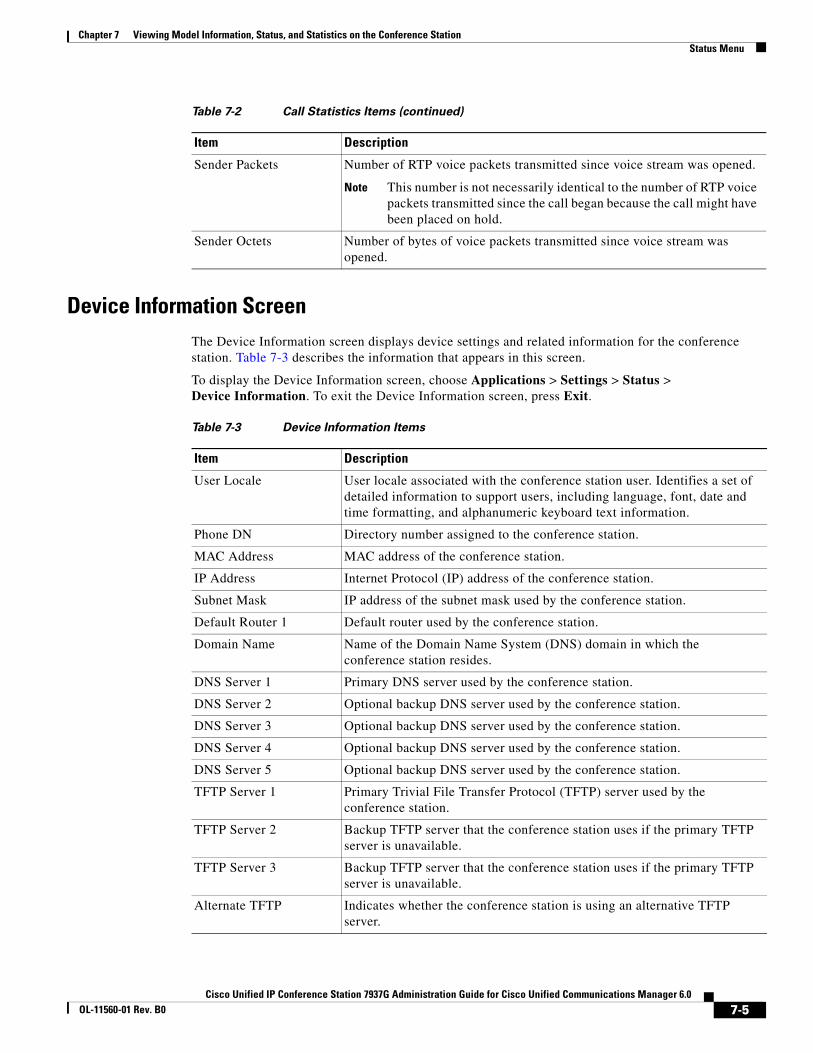
Chapter 7 Viewing Model Information, Status, and Statistics on the Conference StationStatus Menu
Device Information ScreenThe Device Information screen displays device settings and related information for the conference station. Table 7-3 describes the information that appears in this screen.
To display the Device Information screen, choose Applications > Settings > Status > Device Information. To exit the Device Information screen, press Exit.
Sender Packets Number of RTP voice packets transmitted since voice stream was opened.
Note This number is not necessarily identical to the number of RTP voice packets transmitted since the call began because the call might have been placed on hold.
Sender Octets Number of bytes of voice packets transmitted since voice stream was opened.
Table 7-2 Call Statistics Items (continued)
Item Description
Table 7-3 Device Information Items
Item Description
User Locale User locale associated with the conference station user. Identifies a set of detailed information to support users, including language, font, date and time formatting, and alphanumeric keyboard text information.
Phone DN Directory number assigned to the conference station.
MAC Address MAC address of the conference station.
IP Address Internet Protocol (IP) address of the conference station.
Subnet Mask IP address of the subnet mask used by the conference station.
Default Router 1 Default router used by the conference station.
Domain Name Name of the Domain Name System (DNS) domain in which the conference station resides.
DNS Server 1 Primary DNS server used by the conference station.
DNS Server 2 Optional backup DNS server used by the conference station.
DNS Server 3 Optional backup DNS server used by the conference station.
DNS Server 4 Optional backup DNS server used by the conference station.
DNS Server 5 Optional backup DNS server used by the conference station.
TFTP Server 1 Primary Trivial File Transfer Protocol (TFTP) server used by the conference station.
TFTP Server 2 Backup TFTP server that the conference station uses if the primary TFTP server is unavailable.
TFTP Server 3 Backup TFTP server that the conference station uses if the primary TFTP server is unavailable.
Alternate TFTP Indicates whether the conference station is using an alternative TFTP server.
7-5Cisco Unified IP Conference Station 7937G Administration Guide for Cisco Unified Communications Manager 6.0
OL-11560-01 Rev. B0

Chapter 7 Viewing Model Information, Status, and Statistics on the Conference StationStatus Menu
Operational VLAN ID Auxiliary Virtual Local Area Network (VLAN) configured on a Cisco catalyst switch in which the conference station is a member.
Admin. VLAN ID Auxiliary VLAN in which the conference station is a member.
Time and Date Time and date obtained from the Date/Time Group in Cisco Unified Communications Manager to which the conference station belongs.
Ethernet Configuration Speed and duplex of the Ethernet port (labeled LAN on the conference station).
Table 7-3 Device Information Items (continued)
Item Description
7-6Cisco Unified IP Conference Station 7937G Administration Guide for Cisco Unified Communications Manager 6.0
OL-11560-01 Rev. B0

Cisco Unified IP Conference Station 7937G Administration GuOL-11560-01 Rev. B0
C H A P T E R 8
Monitoring the Conference Station RemotelyEach Cisco Unified IP Conference Station 7937G has a web page from which you can view a variety of information about the conference station, including:
• Device information
• Network configuration information
• Ethernet information
• Device logs
• Streaming statistics
This chapter describes the information that you can obtain from the conference station’s web page. You can use this information to remotely monitor the operation of a conference station and to assist with troubleshooting.
You can also obtain much of this information directly from a conference station. For more information, see Chapter 7, “Viewing Model Information, Status, and Statistics on the Conference Station.”
For more information about troubleshooting the conference station, see Chapter 9, “Troubleshooting and Maintenance.”
This chapter includes these topics:
• Accessing the Web Page for a Conference Station, page 8-2
• Disabling and Enabling Web Page Access, page 8-2
• Device Information, page 8-3
• Network Configuration, page 8-4
• Ethernet Information, page 8-6
• Device Logging, page 8-8
• Streaming Statistics, page 8-8
8-1ide for Cisco Unified Communications Manager 6.0
Chapter 8 Monitoring the Conference Station RemotelyAccessing the Web Page for a Conference Station
Accessing the Web Page for a Conference StationTo access the web page for a conference station, perform these steps:
Note If you cannot access the web page, it may be disabled. See the “Disabling and Enabling Web Page Access” section on page 8-2 for more information.
Procedure
Step 1 Obtain the IP address of the conference station using one of these methods:
• From Cisco Unified Communications Manager Administration, choose Device > Phone. Enter search criteria to locate the conference station, and then click the conference station name. Conference stations registered with Cisco Unified Communications Manager display the IP address at the top of the Phone Configuration web page.
• On the conference station, choose Applications > Settings > Network Configuration. Then, scroll to the IP Address option.
Step 2 Open a web browser and enter the following URL, where IP_address is the IP address of the conference station:
http://IP_address
The web page for a conference station includes these hyperlinks:
• Device Information—Displays device settings and related information for the conference station. For more information, see the “Device Information” section on page 8-3.
• Network Configuration—Displays network configuration information and information about other conference station settings. For more information, see the “Network Configuration” section on page 8-4.
• Ethernet Information—Displays network statistics. For more information, see the “Ethernet Information” section on page 8-6.
• Device Logging—Displays messages that might be useful to Cisco TAC if you require assistance with troubleshooting. For more information, see the “Device Logging” section on page 8-8.
• Streaming Statistics—Displays call statistics. For more information, see the “Streaming Statistics” section on page 8-8.
Disabling and Enabling Web Page AccessFor security purposes, you may choose to prevent access to the web pages for a conference station. If you do so, you will prevent access to the web pages that are described in this chapter and to the conference station’s User Options web pages.
8-2Cisco Unified IP Conference Station 7937G Administration Guide for Cisco Unified Communications Manager 6.0
OL-11560-01 Rev. B0
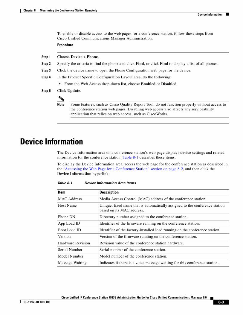
Chapter 8 Monitoring the Conference Station RemotelyDevice Information
To enable or disable access to the web pages for a conference station, follow these steps from Cisco Unified Communications Manager Administration:
Procedure
Step 1 Choose Device > Phone.
Step 2 Specify the criteria to find the phone and click Find, or click Find to display a list of all phones.
Step 3 Click the device name to open the Phone Configuration web page for the device.
Step 4 In the Product Specific Configuration Layout area, do the following:
• From the Web Access drop-down list, choose Enabled or Disabled.
Step 5 Click Update.
Note Some features, such as Cisco Quality Report Tool, do not function properly without access to the conference station web pages. Disabling web access also affects any serviceability application that relies on web access, such as CiscoWorks.
Device InformationThe Device Information area on a conference station’s web page displays device settings and related information for the conference station. Table 8-1 describes these items.
To display the Device Information area, access the web page for the conference station as described in the “Accessing the Web Page for a Conference Station” section on page 8-2, and then click the Device Information hyperlink.
Table 8-1 Device Information Area Items
Item Description
MAC Address Media Access Control (MAC) address of the conference station.
Host Name Unique, fixed name that is automatically assigned to the conference station based on its MAC address.
Phone DN Directory number assigned to the conference station.
App Load ID Identifier of the firmware running on the conference station.
Boot Load ID Identifier of the factory-installed load running on the conference station.
Version Version of the firmware running on the conference station.
Hardware Revision Revision value of the conference station hardware.
Serial Number Serial number of the conference station.
Model Number Model number of the conference station.
Message Waiting Indicates if there is a voice message waiting for this conference station.
8-3Cisco Unified IP Conference Station 7937G Administration Guide for Cisco Unified Communications Manager 6.0
OL-11560-01 Rev. B0
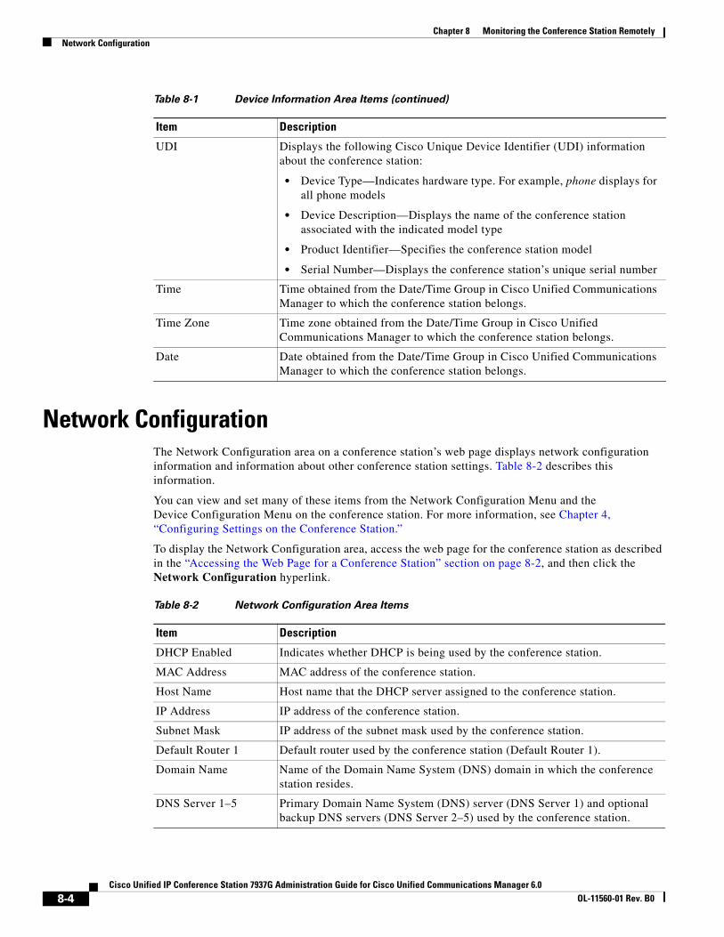
Chapter 8 Monitoring the Conference Station RemotelyNetwork Configuration
Network ConfigurationThe Network Configuration area on a conference station’s web page displays network configuration information and information about other conference station settings. Table 8-2 describes this information.
You can view and set many of these items from the Network Configuration Menu and the Device Configuration Menu on the conference station. For more information, see Chapter 4, “Configuring Settings on the Conference Station.”
To display the Network Configuration area, access the web page for the conference station as described in the “Accessing the Web Page for a Conference Station” section on page 8-2, and then click the Network Configuration hyperlink.
UDI Displays the following Cisco Unique Device Identifier (UDI) information about the conference station:
• Device Type—Indicates hardware type. For example, phone displays for all phone models
• Device Description—Displays the name of the conference station associated with the indicated model type
• Product Identifier—Specifies the conference station model
• Serial Number—Displays the conference station’s unique serial number
Time Time obtained from the Date/Time Group in Cisco Unified Communications Manager to which the conference station belongs.
Time Zone Time zone obtained from the Date/Time Group in Cisco Unified Communications Manager to which the conference station belongs.
Date Date obtained from the Date/Time Group in Cisco Unified Communications Manager to which the conference station belongs.
Table 8-1 Device Information Area Items (continued)
Item Description
Table 8-2 Network Configuration Area Items
Item Description
DHCP Enabled Indicates whether DHCP is being used by the conference station.
MAC Address MAC address of the conference station.
Host Name Host name that the DHCP server assigned to the conference station.
IP Address IP address of the conference station.
Subnet Mask IP address of the subnet mask used by the conference station.
Default Router 1 Default router used by the conference station (Default Router 1).
Domain Name Name of the Domain Name System (DNS) domain in which the conference station resides.
DNS Server 1–5 Primary Domain Name System (DNS) server (DNS Server 1) and optional backup DNS servers (DNS Server 2–5) used by the conference station.
8-4Cisco Unified IP Conference Station 7937G Administration Guide for Cisco Unified Communications Manager 6.0
OL-11560-01 Rev. B0
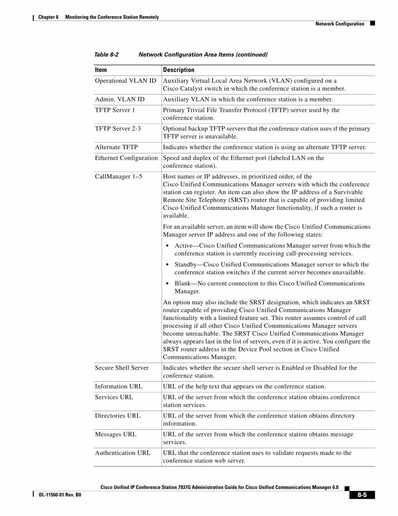
Chapter 8 Monitoring the Conference Station RemotelyNetwork Configuration
Operational VLAN ID Auxiliary Virtual Local Area Network (VLAN) configured on a Cisco Catalyst switch in which the conference station is a member.
Admin. VLAN ID Auxiliary VLAN in which the conference station is a member.
TFTP Server 1 Primary Trivial File Transfer Protocol (TFTP) server used by the conference station.
TFTP Server 2-3 Optional backup TFTP servers that the conference station uses if the primary TFTP server is unavailable.
Alternate TFTP Indicates whether the conference station is using an alternate TFTP server.
Ethernet Configuration Speed and duplex of the Ethernet port (labeled LAN on the conference station).
CallManager 1–5 Host names or IP addresses, in prioritized order, of the Cisco Unified Communications Manager servers with which the conference station can register. An item can also show the IP address of a Survivable Remote Site Telephony (SRST) router that is capable of providing limited Cisco Unified Communications Manager functionality, if such a router is available.
For an available server, an item will show the Cisco Unified Communications Manager server IP address and one of the following states:
• Active—Cisco Unified Communications Manager server from which the conference station is currently receiving call-processing services.
• Standby—Cisco Unified Communications Manager server to which the conference station switches if the current server becomes unavailable.
• Blank—No current connection to this Cisco Unified Communications Manager.
An option may also include the SRST designation, which indicates an SRST router capable of providing Cisco Unified Communications Manager functionality with a limited feature set. This router assumes control of call processing if all other Cisco Unified Communications Manager servers become unreachable. The SRST Cisco Unified Communications Manager always appears last in the list of servers, even if it is active. You configure the SRST router address in the Device Pool section in Cisco Unified Communications Manager.
Secure Shell Server Indicates whether the secure shell server is Enabled or Disabled for the conference station.
Information URL URL of the help text that appears on the conference station.
Services URL URL of the server from which the conference station obtains conference station services.
Directories URL URL of the server from which the conference station obtains directory information.
Messages URL URL of the server from which the conference station obtains message services.
Authentication URL URL that the conference station uses to validate requests made to the conference station web server.
Table 8-2 Network Configuration Area Items (continued)
Item Description
8-5Cisco Unified IP Conference Station 7937G Administration Guide for Cisco Unified Communications Manager 6.0
OL-11560-01 Rev. B0
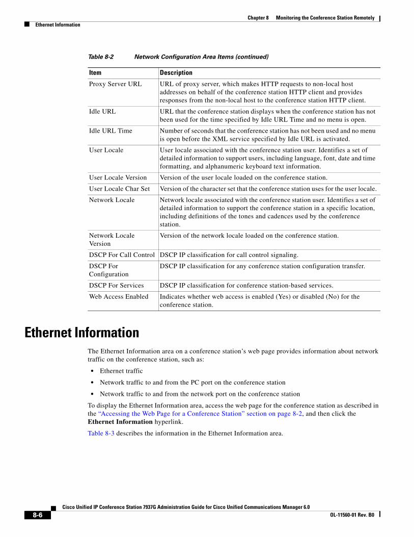
Chapter 8 Monitoring the Conference Station RemotelyEthernet Information
Ethernet InformationThe Ethernet Information area on a conference station’s web page provides information about network traffic on the conference station, such as:
• Ethernet traffic
• Network traffic to and from the PC port on the conference station
• Network traffic to and from the network port on the conference station
To display the Ethernet Information area, access the web page for the conference station as described in the “Accessing the Web Page for a Conference Station” section on page 8-2, and then click the Ethernet Information hyperlink.
Table 8-3 describes the information in the Ethernet Information area.
Proxy Server URL URL of proxy server, which makes HTTP requests to non-local host addresses on behalf of the conference station HTTP client and provides responses from the non-local host to the conference station HTTP client.
Idle URL URL that the conference station displays when the conference station has not been used for the time specified by Idle URL Time and no menu is open.
Idle URL Time Number of seconds that the conference station has not been used and no menu is open before the XML service specified by Idle URL is activated.
User Locale User locale associated with the conference station user. Identifies a set of detailed information to support users, including language, font, date and time formatting, and alphanumeric keyboard text information.
User Locale Version Version of the user locale loaded on the conference station.
User Locale Char Set Version of the character set that the conference station uses for the user locale.
Network Locale Network locale associated with the conference station user. Identifies a set of detailed information to support the conference station in a specific location, including definitions of the tones and cadences used by the conference station.
Network Locale Version
Version of the network locale loaded on the conference station.
DSCP For Call Control DSCP IP classification for call control signaling.
DSCP For Configuration
DSCP IP classification for any conference station configuration transfer.
DSCP For Services DSCP IP classification for conference station-based services.
Web Access Enabled Indicates whether web access is enabled (Yes) or disabled (No) for the conference station.
Table 8-2 Network Configuration Area Items (continued)
Item Description
8-6Cisco Unified IP Conference Station 7937G Administration Guide for Cisco Unified Communications Manager 6.0
OL-11560-01 Rev. B0
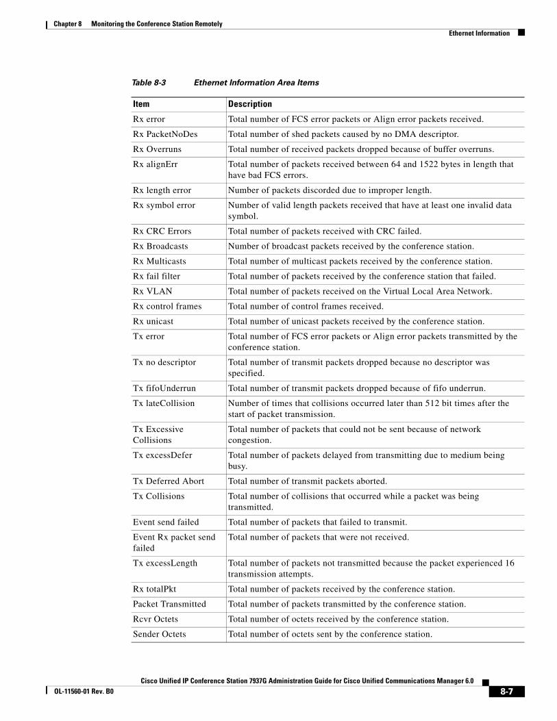
Chapter 8 Monitoring the Conference Station RemotelyEthernet Information
Table 8-3 Ethernet Information Area Items
Item Description
Rx error Total number of FCS error packets or Align error packets received.
Rx PacketNoDes Total number of shed packets caused by no DMA descriptor.
Rx Overruns Total number of received packets dropped because of buffer overruns.
Rx alignErr Total number of packets received between 64 and 1522 bytes in length that have bad FCS errors.
Rx length error Number of packets discorded due to improper length.
Rx symbol error Number of valid length packets received that have at least one invalid data symbol.
Rx CRC Errors Total number of packets received with CRC failed.
Rx Broadcasts Number of broadcast packets received by the conference station.
Rx Multicasts Total number of multicast packets received by the conference station.
Rx fail filter Total number of packets received by the conference station that failed.
Rx VLAN Total number of packets received on the Virtual Local Area Network.
Rx control frames Total number of control frames received.
Rx unicast Total number of unicast packets received by the conference station.
Tx error Total number of FCS error packets or Align error packets transmitted by the conference station.
Tx no descriptor Total number of transmit packets dropped because no descriptor was specified.
Tx fifoUnderrun Total number of transmit packets dropped because of fifo underrun.
Tx lateCollision Number of times that collisions occurred later than 512 bit times after the start of packet transmission.
Tx Excessive Collisions
Total number of packets that could not be sent because of network congestion.
Tx excessDefer Total number of packets delayed from transmitting due to medium being busy.
Tx Deferred Abort Total number of transmit packets aborted.
Tx Collisions Total number of collisions that occurred while a packet was being transmitted.
Event send failed Total number of packets that failed to transmit.
Event Rx packet send failed
Total number of packets that were not received.
Tx excessLength Total number of packets not transmitted because the packet experienced 16 transmission attempts.
Rx totalPkt Total number of packets received by the conference station.
Packet Transmitted Total number of packets transmitted by the conference station.
Rcvr Octets Total number of octets received by the conference station.
Sender Octets Total number of octets sent by the conference station.
8-7Cisco Unified IP Conference Station 7937G Administration Guide for Cisco Unified Communications Manager 6.0
OL-11560-01 Rev. B0
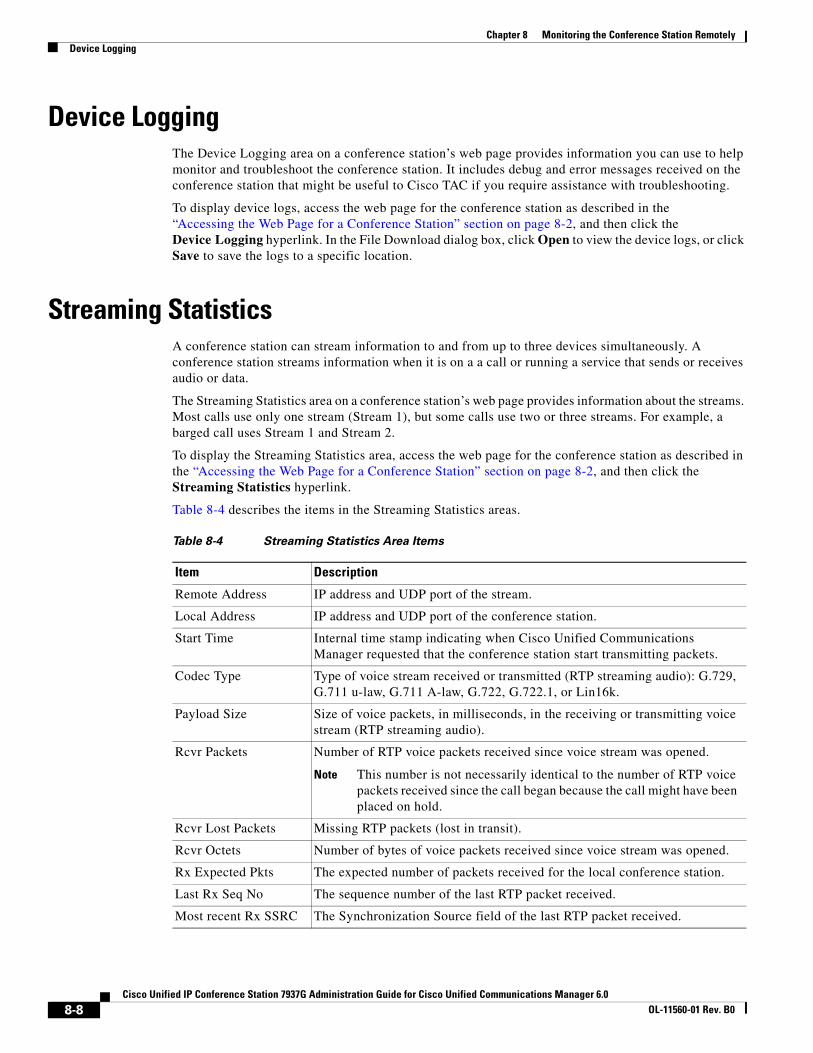
Chapter 8 Monitoring the Conference Station RemotelyDevice Logging
Device LoggingThe Device Logging area on a conference station’s web page provides information you can use to help monitor and troubleshoot the conference station. It includes debug and error messages received on the conference station that might be useful to Cisco TAC if you require assistance with troubleshooting.
To display device logs, access the web page for the conference station as described in the “Accessing the Web Page for a Conference Station” section on page 8-2, and then click the Device Logging hyperlink. In the File Download dialog box, click Open to view the device logs, or click Save to save the logs to a specific location.
Streaming StatisticsA conference station can stream information to and from up to three devices simultaneously. A conference station streams information when it is on a a call or running a service that sends or receives audio or data.
The Streaming Statistics area on a conference station’s web page provides information about the streams. Most calls use only one stream (Stream 1), but some calls use two or three streams. For example, a barged call uses Stream 1 and Stream 2.
To display the Streaming Statistics area, access the web page for the conference station as described in the “Accessing the Web Page for a Conference Station” section on page 8-2, and then click the Streaming Statistics hyperlink.
Table 8-4 describes the items in the Streaming Statistics areas.
Table 8-4 Streaming Statistics Area Items
Item Description
Remote Address IP address and UDP port of the stream.
Local Address IP address and UDP port of the conference station.
Start Time Internal time stamp indicating when Cisco Unified Communications Manager requested that the conference station start transmitting packets.
Codec Type Type of voice stream received or transmitted (RTP streaming audio): G.729, G.711 u-law, G.711 A-law, G.722, G.722.1, or Lin16k.
Payload Size Size of voice packets, in milliseconds, in the receiving or transmitting voice stream (RTP streaming audio).
Rcvr Packets Number of RTP voice packets received since voice stream was opened.
Note This number is not necessarily identical to the number of RTP voice packets received since the call began because the call might have been placed on hold.
Rcvr Lost Packets Missing RTP packets (lost in transit).
Rcvr Octets Number of bytes of voice packets received since voice stream was opened.
Rx Expected Pkts The expected number of packets received for the local conference station.
Last Rx Seq No The sequence number of the last RTP packet received.
Most recent Rx SSRC The Synchronization Source field of the last RTP packet received.
8-8Cisco Unified IP Conference Station 7937G Administration Guide for Cisco Unified Communications Manager 6.0
OL-11560-01 Rev. B0
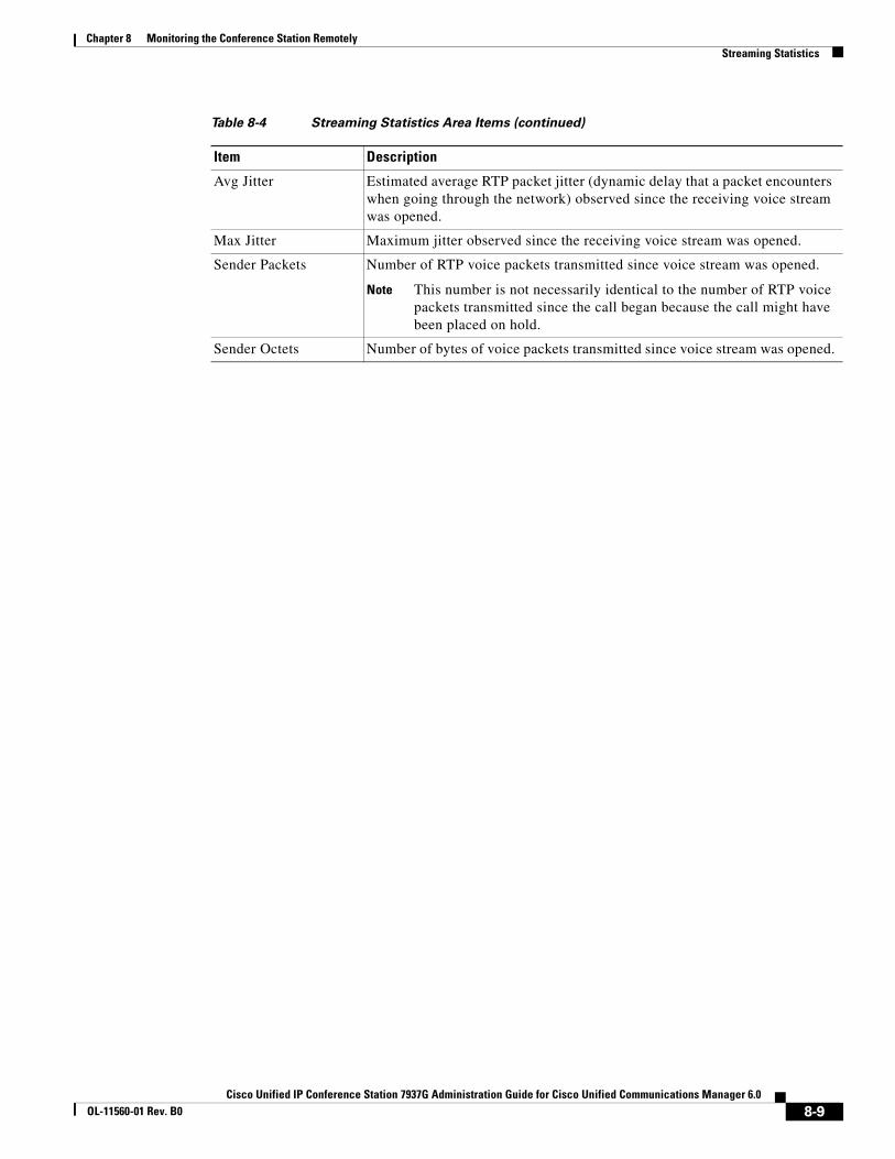
Chapter 8 Monitoring the Conference Station RemotelyStreaming Statistics
Avg Jitter Estimated average RTP packet jitter (dynamic delay that a packet encounters when going through the network) observed since the receiving voice stream was opened.
Max Jitter Maximum jitter observed since the receiving voice stream was opened.
Sender Packets Number of RTP voice packets transmitted since voice stream was opened.
Note This number is not necessarily identical to the number of RTP voice packets transmitted since the call began because the call might have been placed on hold.
Sender Octets Number of bytes of voice packets transmitted since voice stream was opened.
Table 8-4 Streaming Statistics Area Items (continued)
Item Description
8-9Cisco Unified IP Conference Station 7937G Administration Guide for Cisco Unified Communications Manager 6.0
OL-11560-01 Rev. B0

Chapter 8 Monitoring the Conference Station RemotelyStreaming Statistics
8-10Cisco Unified IP Conference Station 7937G Administration Guide for Cisco Unified Communications Manager 6.0
OL-11560-01 Rev. B0

Cisco Unified IP Conference Station 7937G Administration GuOL-11560-01 Rev. B0
C H A P T E R 9
Troubleshooting and MaintenanceThis chapter provides information that can assist you in troubleshooting problems with your Cisco Unified IP Conference Station 7937G or with your IP telephony network. It also explains how to clean and maintain your conference station.
This chapter includes these topics:
• Viewing Call, Device, and Network Information, page 9-1
• Using Ping, page 9-2
• Resolving Startup Problems, page 9-2
• Conference Station Resets Unexpectedly, page 9-7
• General Troubleshooting Tips, page 9-9
• Resetting or Restoring the Conference Station, page 9-11
• Using the Quality Report Tool, page 9-13
• Monitoring the Voice Quality of Calls, page 9-13
• Resolving Conference Call Reception Problems, page 9-14
• Where to Go for More Troubleshooting Information, page 9-15
• Cleaning the Conference Station, page 9-15
Viewing Call, Device, and Network InformationYou can view call, device, and network information through the Applications menu, or remotely through each conference station’s web page. You can use this information to monitor the operation of a conference station to assist with troubleshooting.
To view call, device, and network information directly from the conference station, see Chapter 7, “Viewing Model Information, Status, and Statistics on the Conference Station.”
To view information remotely, see Chapter 8, “Monitoring the Conference Station Remotely.”
9-1ide for Cisco Unified Communications Manager 6.0
Chapter 9 Troubleshooting and MaintenanceUsing Ping
Using PingYou use Ping to test network connectivity to another conference station. Ping is available through the Applications menu.
The Ping menu displays the following two options to test network connectivity to another conference station:
• Ping Arbitrary IP—Allows you to enter the IP address of a conference station to make sure the device is connected to your conference station.
• Ping Arbitrary Host—Allows you to enter the host name of a conference station to make sure the device is connected to your conference station.
To use Ping, follow these steps:
Procedure
Step 1 Choose Applications > Settings > Status > Ping.
Step 2 Press the Up or Down navigation button to select a method to identify the conference station you want to ping. You can enter either an IP address or a Host name.
Step 3 Press the Select button to choose the desired Ping selection method.
Step 4 Enter the IP address or Host name of the conference station you want to ping. Press the */. key on the pad to enter periods (.), and press the << softkey to correct mistakes.
Step 5 Press Submit.
A reply message displays on the screen.
Step 6 Press the Applications button to go back to an idle display screen, or press Exit to return to the Ping screen.
Resolving Startup ProblemsAfter installing a conference station into your network and adding it to Cisco Unified Communications Manager 6.0, the conference station should start up as described in the “Verifying the Conference Station Startup Process” section on page 3-8. If the conference station does not start up properly, see the following sections for troubleshooting information:
• Symptom: The Conference Station Does Not Go Through its Normal Startup Process, page 9-3
• Symptom: The Conference Station Does Not Register with Cisco Unified Communications Manager, page 9-3
• Symptom: Conference Station Unable to Obtain IP Address, page 9-6
9-2Cisco Unified IP Conference Station 7937G Administration Guide for Cisco Unified Communications Manager 6.0
OL-11560-01 Rev. B0
Chapter 9 Troubleshooting and MaintenanceResolving Startup Problems
Symptom: The Conference Station Does Not Go Through its Normal Startup Process
When you connect a conference station into the network port, the conference station should go through its normal startup process as described in the “Verifying the Conference Station Startup Process” section on page 3-8, and the LCD screen should display information. If the conference station does not go through the startup process, the cause may be faulty cables, bad connections, network outages, lack of power, and so on. Or, the conference station may not be functional.
To determine whether the conference station is functional, follow these suggestions to systematically eliminate these other potential problems:
1. Verify that the network port is functional:
– Exchange the Ethernet cables with cables that you know are functional.
– Disconnect a functioning conference station from another port and connect it to this network port to verify the port is active.
– Connect the conference station that will not start up to a different network port that is known to be good.
– Connect the conference station that will not start up directly to the port on the switch, eliminating the patch panel connection in the office.
2. Verify that the conference station is receiving power:
– If you are using external power, verify that the electrical outlet is functional.
– If you are using in-line power, use the external power supply instead.
– If you are using the external power supply, switch with a unit that you know to be functional.
3. If the conference station still does not start up properly, perform a factory reset of the conference station. For instructions, see the “Performing a Factory Reset” section on page 9-12.
If after attempting these solutions, the LCD screen on the conference station does not display any characters after at least five minutes, contact a Cisco technical support representative for additional assistance.
Symptom: The Conference Station Does Not Register with Cisco Unified Communications Manager
To start up properly, the conference station must be connected to the Ethernet network and registered with a Cisco Unified Communications Manager. If the conference station does not start up properly, review the following sections:
• Checking Network Connectivity, page 9-4
• Verifying TFTP Server Settings, page 9-4
• Verifying IP Addressing and Routing, page 9-4
• Verifying DNS Settings, page 9-4
• Verifying Cisco Unified Communications Manager Settings, page 9-5
• Cisco Unified Communications Manager and TFTP Services Are Not Running, page 9-5
• Creating a New Configuration File, page 9-5
• Registering the Conference Station with Cisco Unified Communications Manager, page 9-6
9-3Cisco Unified IP Conference Station 7937G Administration Guide for Cisco Unified Communications Manager 6.0
OL-11560-01 Rev. B0
Chapter 9 Troubleshooting and MaintenanceResolving Startup Problems
Checking Network Connectivity
If the network is down between the conference station and the TFTP server or Cisco Unified Communications Manager, the conference station cannot start up properly. Ensure that the network is currently running.
Verifying TFTP Server Settings
You can determine the IP address of the TFTP server used by the conference station by choosing Applications > Settings > Network Configuration, and then scrolling to the TFTP Server 1 option.
If you have assigned a static IP address to the conference station, you must manually enter a setting for the TFTP Server 1 option. See the “Network Configuration Menu” section on page 4-5.
If you are using Dynamic Host Configuration Protocol (DHCP), the conference station obtains the address for the Trivial File Transfer Protocol (TFTP) server from the DHCP server. A valid TFTP server must be set in DHCP option 150 or option 66 on the DHCP server.
You can also enable the conference station to use an alternate TFTP server. Such a setting is particularly useful if the conference station was recently moved from one location to another. See the “Network Configuration Menu” section on page 4-5 for instructions.
Verifying IP Addressing and Routing
You should verify the Internet Protocol (IP) addressing and routing settings on the conference station. If you are using DHCP, the DHCP server should provide these values. If you have assigned a static IP address to the conference station, you must enter these values manually.
On the conference station, choose Applications > Settings > Network Configuration, and look at the following options:
• DHCP Server—If you have assigned a static IP address to the conference station, you do not need to enter a value for the DHCP Server option. However, if you are using a DHCP server, this option must have a value. If it does not, check your IP routing and VLAN configuration. Refer to Troubleshooting Switch Port Problems, available at this URL: http://www.cisco.com/warp/customer/473/53.shtml
• IP Address, Subnet Mask, Default Router—If you have assigned a static IP address to the conference station, you must manually enter settings for these options. See the “Network Configuration Menu” section on page 4-5 for instructions.
If you are using DHCP, check the IP addresses distributed by your DHCP server. Refer to Understanding and Troubleshooting DHCP in Catalyst Switch or Enterprise Networks, available at this URL: http://www.cisco.com/warp/customer/473/100.html#41
Verifying DNS Settings
If you are using DNS to refer to the TFTP server or to Cisco Unified Communications Manager, you must ensure that you have specified a Domain Name System (DNS) server. Verify this setting by choosing Applications > Settings > Network Configuration, and scrolling to the DNS Server 1 option. You should also verify that there is a CNAME entry in the DNS server for the TFTP server and for Cisco Unified Communications Manager.
You must also ensure that DNS is configured to do reverse look-ups.
9-4Cisco Unified IP Conference Station 7937G Administration Guide for Cisco Unified Communications Manager 6.0
OL-11560-01 Rev. B0

Chapter 9 Troubleshooting and MaintenanceResolving Startup Problems
Verifying Cisco Unified Communications Manager Settings
On the conference station, choose Applications > Settings > Device Configuration > CallManager Configuration, and look at the CallManager 1–5 options. The conference station attempts to open a Transmission Control Protocol (TCP) connection to all the Cisco Unified Communications Manager servers that are part of the assigned Cisco Unified Communications Manager. If none of these options contain IP addresses or show Active or Standby, the conference station is not properly registered with Cisco Unified Communications Manager. See the “Registering the Conference Station with Cisco Unified Communications Manager” section on page 9-6 for tips on resolving this problem.
Cisco Unified Communications Manager and TFTP Services Are Not Running
If the Cisco Unified Communications Manager or TFTP services are not running, conference stations may not be able to start up properly. However, in such a situation, it is likely that you are experiencing a system-wide failure and that other conference stations and devices are unable to start up properly.
If the Cisco Unified Communications Manager service is not running, all devices on the network that rely on it to make conference station calls will be affected. If the TFTP service is not running, many devices will not be able to start up successfully.
To start a service, follow these steps:
Procedure
Step 1 From Cisco Unified Communications Manager Administration, choose Cisco Unified Serviceability from the Navigation drop-down list that displays in the upper, right corner of the window, and then click Go.
Step 2 Choose Tools > Control Center - Network Services.
Step 3 Choose the primary Cisco Unified Communications Manager server from the Server drop-down list.
The page displays the service names for the server that you chose, the status of the services, and a service control panel to stop or start a service.
Step 4 If a service has stopped, click its radio button, and then click Start.
Creating a New Configuration File
If you continue to have problems with a particular conference station that other suggestions in this chapter do not resolve, the configuration file may be corrupt.
To create a new configuration file, follow these steps:
Procedure
Step 1 In Cisco Unified Communications Manager Administration, choose Device > Phone. Enter search criteria to locate the conference station experiencing problems, and then click the device name.
Step 2 In the Phone Configuration window, click Delete to remove the conference station from Cisco Unified Communications Manager.
9-5Cisco Unified IP Conference Station 7937G Administration Guide for Cisco Unified Communications Manager 6.0
OL-11560-01 Rev. B0

Chapter 9 Troubleshooting and MaintenanceResolving Startup Problems
Step 3 Add the conference station back to Cisco Unified Communications Manager. See the “Adding Conference Stations to the Cisco Unified Communications Manager Database” section on page 2-7 for details.
Step 4 Power cycle the conference station.
Note When you remove a conference station from the Cisco Unified Communications Manager database, its configuration file is deleted from the Cisco Unified Communications Manager TFTP server. The conference station’s directory number remains in the Cisco Unified Communications Manager. It becomes an “unassigned DN” and can be used by another device. If unassigned DNs are not used by other devices, delete them from Cisco Unified Communications Manager. You can use the Route Plan Report to view and delete unassigned reference numbers. Refer to Cisco Unified Communications Manager Administration Guide for more information.
Registering the Conference Station with Cisco Unified Communications Manager
A conference station can register with a Cisco Unified Communications Manager server only if the conference station has been added to the server or if auto-registration is enabled. Review the information and procedures in the “Adding Conference Stations to the Cisco Unified Communications Manager Database” section on page 2-7 to ensure that the conference station has been added to Cisco Unified Communications Manager.
To verify that the conference station is in the Cisco Unified Communications Manager database, choose Device > Phone from Cisco Unified Communications Manager Administration and search for the conference station based on its MAC Address. For information about determining a MAC address, see the “Determining the MAC Address of a Conference Station” section on page 2-9.
If the conference station is already in the Cisco Unified Communications Manager database, its configuration file may be damaged. See the “Creating a New Configuration File” section on page 9-5 for assistance.
Symptom: Conference Station Unable to Obtain IP AddressIf a conference station is unable to obtain an IP address when it starts up, the conference station may not be on the same network or VLAN as the DHCP server, or the switch port to which the conference station is connected may be disabled.
Make sure that the network or VLAN to which the conference station is connected has access to the DHCP server, and make sure that the switch port is enabled.
9-6Cisco Unified IP Conference Station 7937G Administration Guide for Cisco Unified Communications Manager 6.0
OL-11560-01 Rev. B0
Chapter 9 Troubleshooting and MaintenanceConference Station Resets Unexpectedly
Conference Station Resets UnexpectedlyIf users report that their conference stations are resetting during calls or while idle on their desk, you should investigate the cause. If the network connection and Cisco Unified Communications Manager connection are stable, a conference station should not reset on its own.
Typically, a conference station resets if it has problems connecting to the Ethernet network or to Cisco Unified Communications Manager. These sections can help you identify the cause of a conference station resetting in your network:
• Verifying Physical Connection, page 9-7
• Identifying Intermittent Network Outages, page 9-7
• Verifying DHCP Settings, page 9-7
• Checking Static IP Address Settings, page 9-8
• Verifying Voice VLAN Configuration, page 9-8
• Eliminating DNS or Other Connectivity Errors, page 9-8
• Checking Power Connection, page 9-9
Verifying Physical ConnectionVerify that the Ethernet connection to which the conference station is connected is up. For example, check if the particular port or switch to which the conference station is connected is down and that the switch is not rebooting. Also make sure that there are no cable breaks.
Identifying Intermittent Network OutagesIntermittent network outages affect data and voice traffic differently. Your network might have been experiencing intermittent outages without detection. If so, data traffic can resend lost packets and verify that packets are received and transmitted. However, voice traffic cannot recapture lost packets. Rather than retransmitting a lost network connection, the conference station resets and attempts to reconnect its network connection.
If you are experiencing problems with the voice network, you should investigate whether an existing problem is simply being exposed.
Verifying DHCP SettingsFollow this process to help determine if the conference station has been properly configured to use DHCP:
1. Verify that you have properly configured the conference station to use DHCP. See the “Network Configuration Menu” section on page 4-5 for more information.
2. Verify that the DHCP server has been set up properly.
3. Verify the DHCP lease duration. Cisco recommends that you set it to 8 days.
Conference stations send messages with request type 151 to renew their DHCP address leases. If the DHCP server expects messages with request type 150, the lease will be denied, forcing the conference station to restart and request a new IP address from the DHCP server.
9-7Cisco Unified IP Conference Station 7937G Administration Guide for Cisco Unified Communications Manager 6.0
OL-11560-01 Rev. B0
Chapter 9 Troubleshooting and MaintenanceConference Station Resets Unexpectedly
Checking Static IP Address SettingsIf the conference station has been assigned a static IP address, verify that you have entered the correct settings. See the “Network Configuration Menu” section on page 4-5 for more information.
Verifying Voice VLAN ConfigurationIf the conference station appears to reset during heavy network usage (for example, following extensive web surfing on a computer connected to the same switch as conference station), it is likely that you do not have a voice VLAN configured.
Isolating the conference stations on a separate auxiliary VLAN increases the quality of the voice traffic. See the “Understanding Interactions with Other Cisco Unified IP Communications Products” section on page 2-1 for details.
Eliminating DNS or Other Connectivity ErrorsIf the conference station continues to reset, follow these steps to eliminate DNS or other connectivity errors:
Procedure
Step 1 Use the Erase softkey to reset conference station settings to their default values. See the “Resetting or Restoring the Conference Station” section on page 9-11 for details.
Step 2 Modify DHCP and IP settings:
a. Disable DHCP.
b. Assign static IP values to the conference station. Use the same default router setting used for other functioning conference stations.
c. Assign TFTP server. Use the same TFTP server used for other functioning conference stations.
See the “Network Configuration Menu” section on page 4-5 for instructions on modifying the above three settings.
Step 3 On the Cisco Unified Communications Manager server, verify that the local host files have the correct Cisco Unified Communications Manager server name mapped to the correct IP address.
Step 4 From Cisco Unified Communications Manager Administration, choose System > Server to locate the server, and then click the server name. Verify that the server is referred to by its IP address and not by its DNS name.
Step 5 From Cisco Unified Communications Manager Administration, choose Device > Phone to locate the conference station, and then click the conference station name. Verify that you have assigned the correct MAC address to this conference station. For information about determining a MAC address, see the “Determining the MAC Address of a Conference Station” section on page 2-9.
Step 6 Power cycle the conference station.
9-8Cisco Unified IP Conference Station 7937G Administration Guide for Cisco Unified Communications Manager 6.0
OL-11560-01 Rev. B0
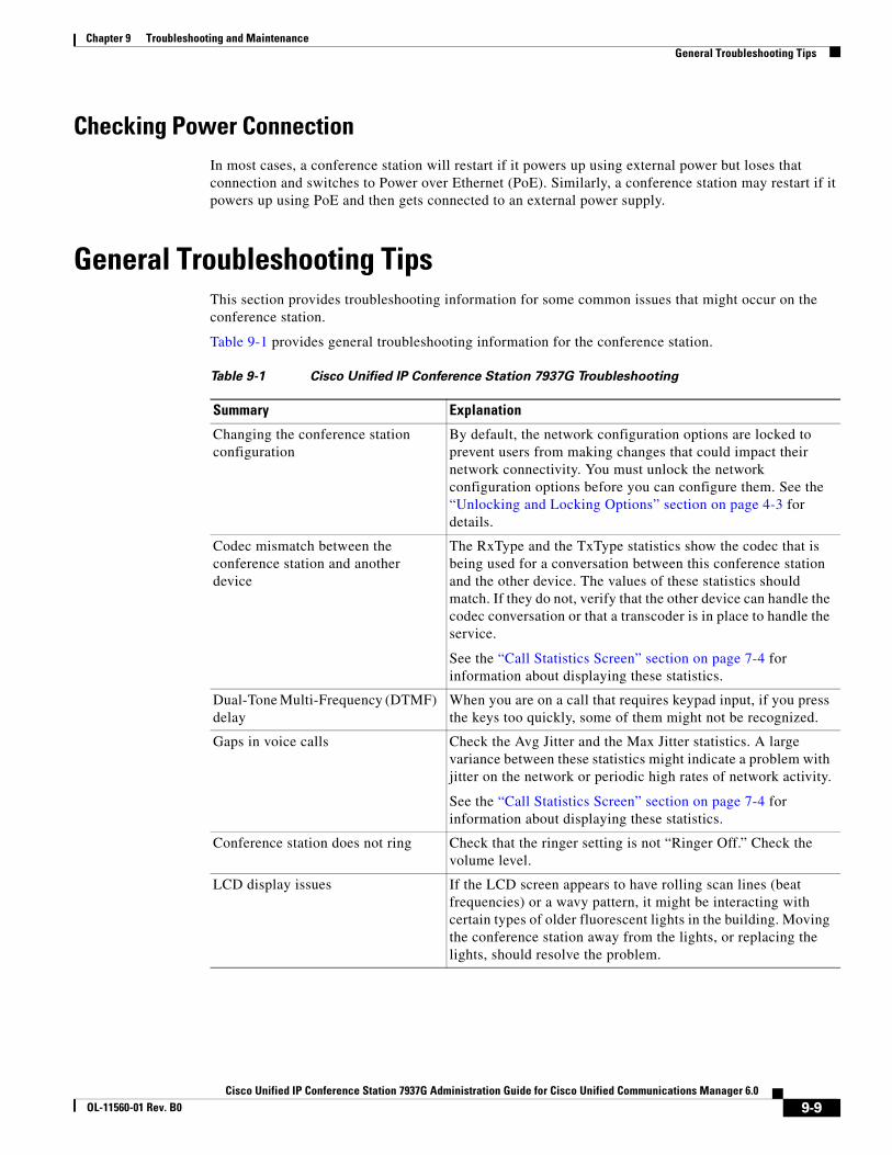
Chapter 9 Troubleshooting and MaintenanceGeneral Troubleshooting Tips
Checking Power ConnectionIn most cases, a conference station will restart if it powers up using external power but loses that connection and switches to Power over Ethernet (PoE). Similarly, a conference station may restart if it powers up using PoE and then gets connected to an external power supply.
General Troubleshooting TipsThis section provides troubleshooting information for some common issues that might occur on the conference station.
Table 9-1 provides general troubleshooting information for the conference station.
Table 9-1 Cisco Unified IP Conference Station 7937G Troubleshooting
Summary Explanation
Changing the conference station configuration
By default, the network configuration options are locked to prevent users from making changes that could impact their network connectivity. You must unlock the network configuration options before you can configure them. See the “Unlocking and Locking Options” section on page 4-3 for details.
Codec mismatch between the conference station and another device
The RxType and the TxType statistics show the codec that is being used for a conversation between this conference station and the other device. The values of these statistics should match. If they do not, verify that the other device can handle the codec conversation or that a transcoder is in place to handle the service.
See the “Call Statistics Screen” section on page 7-4 for information about displaying these statistics.
Dual-Tone Multi-Frequency (DTMF) delay
When you are on a call that requires keypad input, if you press the keys too quickly, some of them might not be recognized.
Gaps in voice calls Check the Avg Jitter and the Max Jitter statistics. A large variance between these statistics might indicate a problem with jitter on the network or periodic high rates of network activity.
See the “Call Statistics Screen” section on page 7-4 for information about displaying these statistics.
Conference station does not ring Check that the ringer setting is not “Ringer Off.” Check the volume level.
LCD display issues If the LCD screen appears to have rolling scan lines (beat frequencies) or a wavy pattern, it might be interacting with certain types of older fluorescent lights in the building. Moving the conference station away from the lights, or replacing the lights, should resolve the problem.
9-9Cisco Unified IP Conference Station 7937G Administration Guide for Cisco Unified Communications Manager 6.0
OL-11560-01 Rev. B0
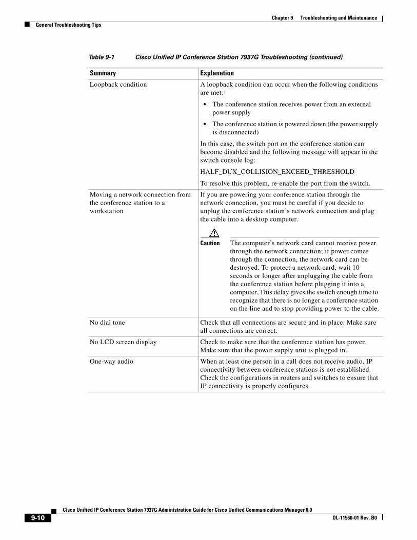
Chapter 9 Troubleshooting and MaintenanceGeneral Troubleshooting Tips
Loopback condition A loopback condition can occur when the following conditions are met:
• The conference station receives power from an external power supply
• The conference station is powered down (the power supply is disconnected)
In this case, the switch port on the conference station can become disabled and the following message will appear in the switch console log:
HALF_DUX_COLLISION_EXCEED_THRESHOLD
To resolve this problem, re-enable the port from the switch.
Moving a network connection from the conference station to a workstation
If you are powering your conference station through the network connection, you must be careful if you decide to unplug the conference station’s network connection and plug the cable into a desktop computer.
Caution The computer’s network card cannot receive power through the network connection; if power comes through the connection, the network card can be destroyed. To protect a network card, wait 10 seconds or longer after unplugging the cable from the conference station before plugging it into a computer. This delay gives the switch enough time to recognize that there is no longer a conference station on the line and to stop providing power to the cable.
No dial tone Check that all connections are secure and in place. Make sure all connections are correct.
No LCD screen display Check to make sure that the conference station has power. Make sure that the power supply unit is plugged in.
One-way audio When at least one person in a call does not receive audio, IP connectivity between conference stations is not established. Check the configurations in routers and switches to ensure that IP connectivity is properly configures.
Table 9-1 Cisco Unified IP Conference Station 7937G Troubleshooting (continued)
Summary Explanation
9-10Cisco Unified IP Conference Station 7937G Administration Guide for Cisco Unified Communications Manager 6.0
OL-11560-01 Rev. B0
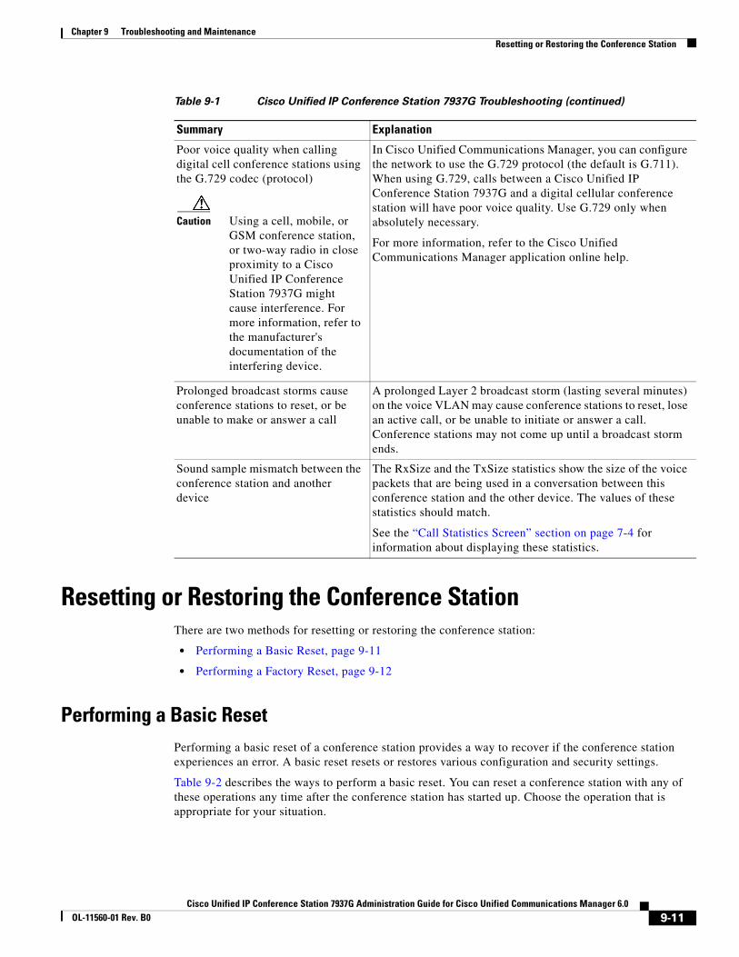
Chapter 9 Troubleshooting and MaintenanceResetting or Restoring the Conference Station
Resetting or Restoring the Conference StationThere are two methods for resetting or restoring the conference station:
• Performing a Basic Reset, page 9-11
• Performing a Factory Reset, page 9-12
Performing a Basic ResetPerforming a basic reset of a conference station provides a way to recover if the conference station experiences an error. A basic reset resets or restores various configuration and security settings.
Table 9-2 describes the ways to perform a basic reset. You can reset a conference station with any of these operations any time after the conference station has started up. Choose the operation that is appropriate for your situation.
Poor voice quality when calling digital cell conference stations using the G.729 codec (protocol)
Caution Using a cell, mobile, or GSM conference station, or two-way radio in close proximity to a Cisco Unified IP Conference Station 7937G might cause interference. For more information, refer to the manufacturer's documentation of the interfering device.
In Cisco Unified Communications Manager, you can configure the network to use the G.729 protocol (the default is G.711). When using G.729, calls between a Cisco Unified IP Conference Station 7937G and a digital cellular conference station will have poor voice quality. Use G.729 only when absolutely necessary.
For more information, refer to the Cisco Unified Communications Manager application online help.
Prolonged broadcast storms cause conference stations to reset, or be unable to make or answer a call
A prolonged Layer 2 broadcast storm (lasting several minutes) on the voice VLAN may cause conference stations to reset, lose an active call, or be unable to initiate or answer a call. Conference stations may not come up until a broadcast storm ends.
Sound sample mismatch between the conference station and another device
The RxSize and the TxSize statistics show the size of the voice packets that are being used in a conversation between this conference station and the other device. The values of these statistics should match.
See the “Call Statistics Screen” section on page 7-4 for information about displaying these statistics.
Table 9-1 Cisco Unified IP Conference Station 7937G Troubleshooting (continued)
Summary Explanation
9-11Cisco Unified IP Conference Station 7937G Administration Guide for Cisco Unified Communications Manager 6.0
OL-11560-01 Rev. B0
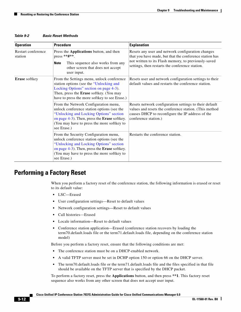
Chapter 9 Troubleshooting and MaintenanceResetting or Restoring the Conference Station
Performing a Factory ResetWhen you perform a factory reset of the conference station, the following information is erased or reset to its default value:
• LSC—Erased
• User configuration settings—Reset to default values
• Network configuration settings—Reset to default values
• Call histories—Erased
• Locale information—Reset to default values
• Conference station application—Erased (conference station recovers by loading the term70.default.loads file or the term71.default.loads file, depending on the conference station model)
Before you perform a factory reset, ensure that the following conditions are met:
• The conference station must be on a DHCP-enabled network.
• A valid TFTP server must be set in DCHP option 150 or option 66 on the DHCP server.
• The term70.default.loads file or the term71.default.loads file and the files specified in that file should be available on the TFTP server that is specified by the DHCP packet.
To perform a factory reset, press the Applications button, and then press **1. This factory reset sequence also works from any other screen that does not accept user input.
Table 9-2 Basic Reset Methods
Operation Procedure Explanation
Restart conference station
Press the Applications button, and then press **#**.
Note This sequence also works from any other screen that does not accept user input.
Resets any user and network configuration changes that you have made, but that the conference station has not written to its Flash memory, to previously-saved settings, then restarts the conference station.
Erase softkey From the Settings menu, unlock conference station options (see the “Unlocking and Locking Options” section on page 4-3). Then, press the Erase softkey. (You may have to press the more softkey to see Erase.)
Resets user and network configuration settings to their default values and restarts the conference station.
From the Network Configuration menu, unlock conference station options (see the “Unlocking and Locking Options” section on page 4-3). Then, press the Erase softkey. (You may have to press the more softkey to see Erase.)
Resets network configuration settings to their default values and resets the conference station. (This method causes DHCP to reconfigure the IP address of the conference station.)
From the Security Configuration menu, unlock conference station options (see the “Unlocking and Locking Options” section on page 4-3). Then, press the Erase softkey. (You may have to press the more softkey to see Erase.)
Restarts the conference station.
9-12Cisco Unified IP Conference Station 7937G Administration Guide for Cisco Unified Communications Manager 6.0
OL-11560-01 Rev. B0

Chapter 9 Troubleshooting and MaintenanceUsing the Quality Report Tool
Using the Quality Report ToolThe Quality Report Tool (QRT) is a voice quality and general problem-reporting tool for the conference station. The QRT feature is installed as part of Cisco Unified Communications Manager.
You can configure users’ conference stations with QRT. When you do so, users can report problems with conference station calls by pressing the QRT softkey. This softkey is available only when the conference station is in the Connected, Connected Conference, Connected Transfer, and/or OnHook states.
When a user presses the QRT softkey, a list of problem categories appears. The user selects the appropriate problem category and this feedback is logged in an XML file. Actual information logged depends on the user selection and whether the destination device is a conference station.
For more information about using QRT, refer to Cisco Unified Communications Manager Features and Services Guide.
Monitoring the Voice Quality of CallsTo measure the voice quality of calls that are sent and received within the network, conference stations use these statistical metrics that are based on concealment events. The DSP plays concealment frames to mask frame loss in the voice packet stream.
• Concealment Ratio metrics—Show the ratio of concealment frames over total speech frames. An interval conceal ratio is calculated every 3 seconds.
• Concealed Second metrics—Show the number of seconds in which the DSP plays concealment frames due to lost frames. A severely “concealed second” is a second in which the DSP plays more than five percent concealment frames.
• MOS-LQK metrics—Use a numeric score to estimate the relative voice listening quality. The conference station calculates the mean opinion score (MOS) for listening quality (LQK) based audible concealment events due to frame loss in the preceding 8 seconds, and includes perceptual weighting factors such as codec type and frame size.
MOS LQK scores are produced by a Cisco proprietary algorithm that is an implementation of P.VTQ, an ITU provisional standard.
Note Concealment ratio and concealment seconds are primary measurements based on frame loss while MOS LQK scores project a “human-weighted” version of the same information on a scale from 5 (excellent) to 1 (bad) for measuring listening quality.
Listening quality scores (MOS LQK) relate to the clarity or sound of the received voice signal. Conversational quality scores (MOS CQ such as G.107) include impairment factors, such as delay, that degrade the natural flow of conversation.
For information about configuring voice quality metrics for conference stations, refer to Cisco Unified Communications Manager System Guide, “Cisco Unified IP Phones” chapter, “Phone Features” section.
You can access voice quality metrics from the conference station by using the Call Statistics screen (see the “Call Statistics Screen” section on page 7-4) or remotely by using Streaming Statistics (see Chapter 8, “Monitoring the Conference Station Remotely”).
To use the metrics for monitoring voice quality, note the typical scores under normal conditions of zero packet loss, and use the metrics as a baseline for comparison.
9-13Cisco Unified IP Conference Station 7937G Administration Guide for Cisco Unified Communications Manager 6.0
OL-11560-01 Rev. B0

Chapter 9 Troubleshooting and MaintenanceResolving Conference Call Reception Problems
It is important to distinguish significant changes from random changes in metrics. Significant changes are scores that change about 0.2 MOS or greater and persist in calls that last longer than 30 seconds. Conceal Ratio changes should indicate greater than 3 percent frame loss.
MOS LQK scores can vary based on the codec that the conference station uses. The following codecs provide these maximum MOS LQK scores under normal conditions with zero frame loss:
• G.711 codec gives 4.5 score
• G.719A/ AB gives 3.7 score
A Conceal Ratio of zero indicates that the IP network is delivering frames and packets on time with no loss.
When you observe significant and persistent changes to metrics, use Table 9-3 for general troubleshooting information.
Note Voice quality metrics do not account for noise or distortion, only frame loss.
Resolving Conference Call Reception ProblemsTo ensure optimum performance with the conference station and the external microphones, see “Guidelines for Best Performance” section on page 3-9 and the “Conference Room Setup Examples” section on page 3-10.
Table 9-3 Changes to Voice Quality Metrics
Metric Change Condition
MOS LQK scores decrease significantly
Network impairment from packet loss or high jitter:
• Average MOS LQK decreases could indicate widespread and uniform impairment.
• Individual MOS LQK decreases indicate bursty impairment.
Cross-check with Conceal Ratio and Conceal Seconds for evidence of packet loss and jitter.
MOS LQK scores decrease significantly
• Check to see if the conference station is using a different codec than expected (RxType and TxType).
• Check to see if the MOS LQK version changed after a firmware upgrade.
Conceal Ratio and Conceal Seconds increase significantly
• Network impairment from packet loss or high jitter.
Conceal Ratio is near or at zero, but the voice quality is poor
• Noise or distortion in the audio channel such as echo or audio levels.
• Tandem calls that undergo multiple encode/decode such as calls to a cellular network or calling card network.
Check packet transmit (TxCnt) and packet receive (RxCnt) counters to verify that voice packets are flowing.
9-14Cisco Unified IP Conference Station 7937G Administration Guide for Cisco Unified Communications Manager 6.0
OL-11560-01 Rev. B0

Chapter 9 Troubleshooting and MaintenanceWhere to Go for More Troubleshooting Information
Where to Go for More Troubleshooting InformationIf you have additional questions about troubleshooting the conference station, several Cisco.com web sites can provide you with more tips. Choose from the sites available for your access level.
• Conference Station Troubleshooting Resources:
http://www.cisco.com/en/US/products/hw/conference stations/ps379/tsd_products_support_series_home.html
• Cisco Products and Services (Technical Support and Documentation):
http://www.cisco.com/en/US/products/sw/voicesw/tsd_products_support_ category_home.html
Cleaning the Conference StationTo clean your conference station, use a soft, dry cloth to wipe the conference station and the LCD screen. Do not apply liquids or powders directly on the conference station. As with all non-weather-proof electronics, liquids and powders can damage the components and cause failures.
9-15Cisco Unified IP Conference Station 7937G Administration Guide for Cisco Unified Communications Manager 6.0
OL-11560-01 Rev. B0

Chapter 9 Troubleshooting and MaintenanceCleaning the Conference Station
9-16Cisco Unified IP Conference Station 7937G Administration Guide for Cisco Unified Communications Manager 6.0
OL-11560-01 Rev. B0

Cisco Unified IP Conference Station 7937G Administration Guide forOL-11560-01 Rev. B0
A
P P E N D I X A Providing Information to Users Via a WebsiteIf you are a system administrator, you are likely the primary source of information for conference stations in your network or company. It is important to provide current and thorough information about the Cisco Unified IP Conference Station 7937G to end users.
Cisco recommends that you create a web page on your internal support site that provides end users with important information about their conference stations.
Consider including the following types of information on this site:
• How Users Obtain Support for the Conference Station, page A-1
• How Users Get Copies of Conference Station Manuals, page A-1
• How Users Subscribe to Services and Configure Conference Station Features, page A-2
• How Users Access a Voice Messaging System, page A-2
• How Users Configure Personal Directory Entries, page A-3
How Users Obtain Support for the Conference StationTo successfully use some of the features on the conference station (including speed dial, services, and voice messaging system options), users must receive information from you or from your network team or be able to contact you for assistance. Make sure to provide end users with the names of people to contact for assistance and with instructions for contacting those people.
How Users Get Copies of Conference Station ManualsYou should provide end users with access to user documentation for the conference stations. The Cisco Unified IP Conference Station 7937G Phone Guide for Cisco Unified Communications Manager 6.0 includes detailed user instructions for key conference station features.
There are several conference station models available, so to assist users in finding the appropriate documentation on the Cisco website, Cisco recommends that you provide links to the current documentation. If you do not want to or cannot send users to the Cisco website, Cisco suggests that you download the PDF files and provide them to end users on your website.
For a list of available documentation, go to the conference station website at this URL:
http://www.cisco.com/en/US/products/hw/phones/ps379/tsd_products_support_series_home.html
For more information about viewing or ordering documentation, see the “Obtaining Documentation, Obtaining Support, and Security Guidelines” section on page xi.
A-1 Cisco Unified Communications Manager 6.0
Appendix A Providing Information to Users Via a WebsiteHow Users Subscribe to Services and Configure Conference Station Features
How Users Subscribe to Services and Configure Conference Station Features
End users can perform a variety of activities using the User Options web pages. These activities include subscribing to services, setting up speed dial and call forwarding numbers, configuring ring settings, and creating a personal address book. Keep in mind that configuring settings on a conference station using a website might be new for your end users. You need to provide as much information as possible to ensure that they can successfully access and use the User Options web pages.
Make sure to provide end users with the following information about the User Options web pages:
• The URL required to access the application. This URL is:
http://server_name:portnumber/ccmuser, where server_name is the host on which the web server is installed, and portnumber is the port number of the web server.
• A user ID, default password, and default PIN are needed to access the application.
These settings correspond to the values you entered when you added the user to Cisco Unified Communications Manager (see the “Adding Users to Cisco Unified Communications Manager” section on page 5-9).
• A brief description of what a web-based, graphical user interface application is, and how to access it with a web browser.
• An overview of the tasks that users can accomplish using the web page.
You can also refer users to Cisco Unified IP Conference Station 7937G Phone Guide for Cisco Unified Communications Manager 6.0, which is available at this URL:
http://www.cisco.com/en/US/products/hw/phones/ps379/tsd_products_support_series_home.html
How Users Access a Voice Messaging SystemCisco Unified Communications Manager lets you integrate with many different voice mail messaging systems, including the Cisco Unity voice messaging system. Because you can integrate with a variety of systems, you must provide users with information about how to use your specific system.
You should provide this information to each user:
• How to access the voice mail messaging system account.
Make sure that you have used Cisco Unified Communications Manager to configure the Messages button on the conference station.
• Initial password for accessing the voice messaging system.
Make sure that you have configured a default voice messaging system password for all users.
• How the phone indicates that voice messages are waiting.
Make sure that you have used Cisco Unified Communications Manager to set up a message waiting indicator (MWI) method.
A-2Cisco Unified IP Conference Station 7937G Administration Guide for Cisco Unified Communications Manager 6.0
OL-11560-01 Rev. B0

Appendix A Providing Information to Users Via a WebsiteHow Users Configure Personal Directory Entries
How Users Configure Personal Directory EntriesUsers can configure personal directory entries on the conference station. To configure personal directory, users must have access to the following:
• User Options web pages—Make sure that users know how to access their User Options web pages. See the “How Users Subscribe to Services and Configure Conference Station Features” section on page A-2 for details.
• Cisco Unified Communications Manager Address Book Synchronizer—Make sure to provide users with the installer for this application. To access the installer, log on to Cisco Unified Communications Manager Administration and choose Application > Plugins. Then, locate and click Cisco IP Phone Address Book Synchronizer.
For information about installing the synchronizer, see the “Installing and Configuring the Cisco Unified Communications Manager Address Book Synchronizer” section on page A-3.
Installing and Configuring the Cisco Unified Communications Manager Address Book Synchronizer
Use this tool to synchronize data stored in your Microsoft Windows, Microsoft Outlook, or Microsoft Outlook Express address book(s) with the Cisco Unified Communications Manager directory and Personal Address Book service.
To install the synchronizer, follow these steps:
Procedure
Step 1 Get the synchronizer installer file from your system administrator.
Step 2 Double-click the TabSyncInstall.exe file provided by your system administrator.
The Welcome window appears.
Step 3 Click Next.
The License Agreement window appears.
Step 4 Read the license agreement information and click the I accept the terms in the license agreement radio button, and then click Next.
The Destination Folder window appears.
Step 5 Accept the default directory in which to install the application, and then click Next. Or, change the directory, and then click Next.
The Ready to Install the Program window appears.
Step 6 To install the program, click Install. Or, to review or change any settings, click Back.
The installation wizard installs the application to your computer. When the installation is complete, the Install Shield Wizard Completed window appears.
Step 7 Click Finish.
Step 8 To complete the process, configure the synchronizer. For instructions, see the following procedure.
A-3Cisco Unified IP Conference Station 7937G Administration Guide for Cisco Unified Communications Manager 6.0
OL-11560-01 Rev. B0
Appendix A Providing Information to Users Via a WebsiteHow Users Configure Personal Directory Entries
To configure the synchronizer, follow these steps:
Procedure
Step 1 Open the synchronizer application.
If you accepted the default installation directory, open the application by choosing Start > Programs > Cisco Systems, Inc > Tabsync.
If you chose a different directory, navigate to the installation directory, open the Tabsync folder, and then double-click tabsync.exe.
A Warning dialog box appears.
Step 2 Click OK.
The Cisco Unified Communications Manager Address Book Synchronizer window appears.
Step 3 Click User.
The Cisco Unified Communications Manager User Information dialog box appears.
Step 4 Do the following:
a. In the User Identification field, enter your Cisco Unified Communications Manager User Options username.
b. In the User Password field, enter your Cisco Unified Communications Manager User Options password.
Note If you do not know your username or password, contact your system administrator.
c. Click OK.
The Cisco Unified Communications Manager Address Book Synchronizer window appears.
Step 5 To configure synchronization rules, click Synchronization Rules.
The Synchronization Rules dialog box appears.
Step 6 Select the synchronization rule that you want to use, and then click OK.
The Cisco Unified Communications Manager Address Book Synchronizer window appears.
Step 7 To configure Cisco Unified Communications Manager information, click CCM Server.
The Configure Cisco Unified Communications Manager Server Information dialog box appears.
Step 8 In the Host Name or IP Address field, enter the host name or IP address of Cisco Unified Communications Manager, and then click OK.
Note If you do not have this information, contact your system administrator.
The Cisco Unified Communications Manager Address Book Synchronizer window appears.
Step 9 To start the directory synchronization process, click Synchronize.
During synchronization, if you chose the user intervention for duplicate entries rule and you have duplicate address book entries, you can choose the entry that you want to include in your Personal Address Book.
When synchronization completes, click Exit to close the synchronizer.
A-4Cisco Unified IP Conference Station 7937G Administration Guide for Cisco Unified Communications Manager 6.0
OL-11560-01 Rev. B0

Cisco Unified IP Conference Station 7937G Administration Guide forOL-11560-01 Rev. B0
A
P P E N D I X B Supporting International UsersTranslated and localized versions of the Cisco Unified IP Conference Station 7937G are available in several languages. If you are supporting conference stations in a non-English environment, refer to the following sections to ensure that the phones are set up properly for your users:
• Adding Language Overlays to Conference Station Buttons, page B-1
• Installing the Cisco Unified Communications Locale Installer, page B-1
Adding Language Overlays to Conference Station ButtonsTo support the needs of international users, the button labels on the conference stations exhibit icons rather than text to indicate the purposes of the buttons. You can purchase language-specific text overlays to add to a conference station. To order these language-specific overlays, go to this website:
http://www.overlaypro.com/cisco/
Note Phone overlays are available only for languages in which conference station software has been localized. All languages may not be immediately available, so continue to check the website for updates.
Installing the Cisco Unified Communications Locale InstallerIf you are using conference stations in a locale other than English (United States), you must install the locale-specific version of the Cisco Unified Communications Manager Locale Installer on every Cisco Unified Communications Manager server in the cluster. Installing the locale installer ensures that you have the latest translated text, user and network locales, and country-specific phone tones available for the conference stations. To find locale-specific versions of the Cisco Unified Communications Manager Locale Installer, go to this website:
http://www.cisco.com/kobayashi/sw-center/telephony/callmgr/locale-installer.shtml
For more information, refer to the “Locale Installation” section in the Cisco Unified Communications Operating System Administration Guide.
Note All languages may not be immediately available, so continue to check the website for updates.
B-1 Cisco Unified Communications Manager 6.0

Appendix B Supporting International UsersInstalling the Cisco Unified Communications Locale Installer
B-2Cisco Unified IP Conference Station 7937G Administration Guide for Cisco Unified Communications Manager 6.0
OL-11560-01 Rev. B0
Cisco Unified IP Conference Station 7937G Administration Guide forOL-11560-01 Rev. B0
A
P P E N D I X C Technical SpecificationsThis appendix describes the technical specifications for the Cisco Unified IP Conference Station 7937G.
Physical and Operating Environment Specifications
Specification Value or Range
Operating Temperature 0°C to 40°C (32° to 104°F)
Operating Relative Humidity 10% to 90% (non-condensing)
Storage Temperature -40°C to 85°C (-40°F to 185°F)
Operating Altitude -500 to 6,500 ft. (de-rate 1°C per 1000 ft.)
Height 7.5 cm (3 in.)
Width 38 cm (15 in.)
Depth 38 cm (15 in.)
Weight 1.1 kg (2.42 lb.)
Power • AC/DC adapter (100-240 V~, 50-60 Hz, 500 mA)
• Power over Ethernet (48 V, 380 mA)
• Power interface cable
• Country Cord (orderable)
Conference Room Coverage 20 ft. by 100 ft. (with external microphones)
Audio Range 120Hz to 7000Hz (wide band support)
Loudness 86.5dB at 0.5 meters
Cables One 25-ft. CAT 5 network cable
Cable Distance Requirements As supported by the Ethernet Specification, each conference station must be within 100 meters (330 feet) of a wiring closet.
C-1 Cisco Unified Communications Manager 6.0
Appendix C Technical SpecificationsCable Specifications
Cable SpecificationsThe conference station has the following cabling requirements:
• RJ-45 plug for the 25-ft. CAT 5 cable connection on the bottom of the conference station
• RJ-45 plug for the 25-ft. CAT 5 cable connection on the power interface cable
• 6-ft., 48-volt connector to the power interface cable
C-2Cisco Unified IP Conference Station 7937G Administration Guide for Cisco Unified Communications Manager 6.0
OL-11560-01 Rev. B0
Cisco Unified IP Conference Station 7937G Administration GuOL-11560-01 Rev. B0
I N D E X
Symbols
.cnf.xml configuration file 2-5
Numerics
802.1X authentication and status 4-13 to 4-14
A
abbreviated dialing 5-2
access to conference station settings 4-1
adding
conference stations manually 2-9
conference stations using auto-registration 2-7
conference stations using auto-registration with TAPS 2-8
conference stations using BAT 2-9
users to Cisco Unified Communications Manager 5-9
address book synchronization tool
about 5-7
configuring A-4
installing A-3
admin. VLAN ID 4-7
alternate TFTP 4-8
applications button 1-3
audio auxiliary port 3-4, 3-5
authentication URL 4-10
auto answer 5-2
auto-registration 2-7, 2-8
B
barge 5-2
BAT 1-9, 2-9
best performance 3-9
Bulk Administration Tool. See BAT
button templates, configuring 5-7
C
cable lock, connecting to conference station 3-7
cabling specifications C-2
caller ID 5-3
call forward 5-2
CallManager 1-5 4-9
CallManager Configuration menu 4-9
call park 5-2
call pickup 5-3
call statistics screen 7-4
call waiting 5-3
cell phone interference 1-1
Cisco Call Back 5-3
Cisco Discovery Protocol. See CDP
Cisco Unified Communications Manager
adding conference stations to 1-9, 2-9
adding conference stations to database of 2-7
Address Book Synchronizer A-3
configuring conference stations in 1-10
interactions with 2-2
server designations 4-9
server states 4-9
verifying settings of 9-5
IN-1ide for Cisco Unified Communications Manager 6.0
Index
Cisco Unified Communications Manager Administration
adding telephony features using 5-1
adding users using 5-9
assigning button templates using 5-7
configuring conference station services using 5-5
configuring conference stations using 1-9
controlling security options using 1-8
controlling user access using 4-1
managing softkeys using 5-8
modifying conference stations settings using 1-6
TABSynch plugin 5-7
Cisco Unified IP Conference Station. See conference station
cleaning the conference station 9-15
Clear softkey 7-2
conference feature 5-3
conference station
accessing Settings menu 4-2
accessing web pages 8-2
adding to Cisco Unified Communications Manager database 2-7, 2-9
adding with auto-registration 2-7
adding with auto-registration and TAPS 2-8
adding with BAT 2-9
cabling requirements C-2
cleaning 9-15
components 1-2 to 1-3
configuration checklist 1-10
configuration files 2-4
configuration requirements 1-9
configuring 1-9 to 1-11
configuring user services 5-8
connecting with cable lock 3-7
display screen 2-3
figure 1-2
installing, checklist 1-12 to 1-13
installing, overview 1-9
installing, procedure 3-4 to 3-7
installing, requirements 1-9
IN-2Cisco Unified IP Conference Station 7937G Administration Guide fo
modifying button templates 5-7
options, locking 4-3
pinging 9-2
ports 3-3 to 3-4
power guidelines for 2-2
providing power to 2-2
registering 2-7
registering with Cisco Unified Communications Manager 2-7, 2-8, 2-9
resetting 9-11
security features for 1-7 to 1-8
settings access 4-1
startup process 2-5 to 2-6, 3-8
supported networking protocols 1-4
technical specifications C-1
troubleshooting 9-1 to 9-15
using LDAP directories 5-6
web page 8-1
configuration files
.cnf.xml 2-5
creating 9-5
modifying 6-1
overview 2-4
XmlDefault.cnf.xml 2-5
configuration menu
displaying 4-2
editing values 4-3
unlocking options 4-3
configuring
button templates 5-7
LDAP directories 5-6
personal directories 5-7
softkey templates 5-8
startup network settings 3-9
user features 5-9
web page access 8-2
connecting to the network 3-5, 3-6
r Cisco Unified Communications Manager 6.0OL-11560-01 Rev. B0
Index
custom phone rings
about 6-2
creating 6-2, 6-3
PCM file requirements 6-3
D
default router 1 4-6
Device Configuration menu
about 4-8 to 4-9
displaying 4-2
editing values 4-3
sub-menus 4-8
device information screen, viewing 7-5
Device Information web page 8-2, 8-3
Device Logging web page 8-2, 8-8
DHCP
description 1-4
troubleshooting 9-7
DHCP enabled 4-5
directories button 1-3
directories URL 4-10
directory numbers, assigning manually 2-9
direct transfer feature 5-3
DNS server
1-5 4-6
troubleshooting 9-8
verifying settings 9-4
domain name, changing 4-6
Domain Name System. See DNS
DSCP for call control 4-12
DSCP for configuration 4-12
DSCP for services 4-12
Dynamic Host Configuration Protocol. See DHCP
Cisco Unified IP Conference Station 7937G AdministOL-11560-01 Rev. B0
E
editing configuration values 4-3
Erase softkey 9-12
Ethernet Configuration 4-8
Ethernet Information web page 8-2, 8-6
ethernet network port 3-3
extension mobility service feature 5-3
external power supply, using 2-2, 2-3, 3-5 to 3-6
F
fast dial service feature 5-3
features
configuring on conference station 1-6
configuring with Cisco Unified Communications Manager 1-6
informing users about 1-7
figures
cable lock connection 3-8
conference station and microphone placement 3-10
conference station components 1-2
conference station using external power 3-5
conference using PoE power 3-4
external microphone connections 3-6
mobile conference station device connection 3-7
file format
RingList.xml 6-2
G
G.729 1-1
G.729a 1-1
G.729ab 1-1
G.729b 1-1
group call pickup feature 5-4
IN-3ration Guide for Cisco Unified Communications Manager 6.0
Index
H
hold feature 5-4
HTTP 1-4
HTTP Configuration menu
about 4-10
options
authentication URL 4-10
directories URL 4-10
idle URL 4-10
idle URL time 4-10
Information URL 4-10
messages URL 4-10
proxy server URL 4-10
services URL 4-10
Hypertext Transfer Protocol. See HTTP
I
iDivert feature 5-4
idle display
configuring 6-4
timeout 4-10
viewing settings 6-4
XML service 4-10, 6-4
idle URL 4-10
idle URL time 4-10
immediate divert feature 5-4
Information URL 4-10
installing
conference stations, checklist 1-12 to 1-13
conference stations, procedure 3-4 to 3-7
conference stations using external power 3-5
conference stations using PoE 3-5
how to prepare for 2-7
microphones 3-6
mobile conference station devices 3-7
network requirements for 3-1
requirements, overview 1-9
IN-4Cisco Unified IP Conference Station 7937G Administration Guide fo
interference, cell phone 1-1
Internet Protocol 1-4
IP address 4-5, 9-4
J
join feature 5-4
K
keypad 1-3
L
layer 2 priority 4-12
LDAP directories, using with conference station 5-6
LED indicators 1-2
Locale Configuration menu
about 4-11
options
network locale 4-11
network locale version 4-11
user locale 4-11
user locale char set 4-11
user locale version 4-11
locking conference station options 4-3
M
MAC address 2-9, 4-8
Malicious Caller Identification. See MCID
MCID feature 5-4
meet-Me conference feature 5-4
messages URL 4-10
message waiting indicator feature 5-4
microphone ports 3-3
microphones, installing 3-6
mobile conference station device, installing 3-7
r Cisco Unified Communications Manager 6.0OL-11560-01 Rev. B0
Index
model information screen 7-1
music-on-hold feature 5-5
mute button 1-3
N
navigation button 1-2
network
connectivity, verifying 9-4
locale 4-11
locale version 4-11
outages, identifying 9-7
port, connecting to 3-5, 3-6
requirements, for installing 3-1
settings, for startup configuration 3-9
statistics 7-2
Network Configuration menu
about 4-5 to 4-8
displaying 4-2
editing values 4-3
locking options 4-3
options
admin. VLAN ID 4-7
alternate TFTP 4-8
default router 1 4-6
DHCP enabled 4-5
DNS server 1-5 4-6
domain name 4-6
ethernet Configuration 4-8
IP address 4-5
MAC Address 4-8
operational VLAN ID 4-7
subnet mask 4-6
TFTP server 1 4-7
TFTP server 2 4-7
unlocking options 4-3
Network Configuration web page 8-2, 8-4
Cisco Unified IP Conference Station 7937G AdministOL-11560-01 Rev. B0
networking protocols
CDP 1-4
DHCP 1-4
HTTP 1-4
IP 1-4
RTP 1-4
SCCP 1-4
TCP 1-5
TFTP 1-5
UDP 1-5
network statistics screen 7-2
O
off-hook 1-3, 5-5
on-hook 1-3, 5-5
operational VLAN ID 4-7
options, locking and unlocking 4-3
P
padlock icon 4-3
PCM file requirements, for custom ring types 6-3
performance guidelines 3-9
personal directories 5-7, A-3
physical connection, verifying 9-7
pinging conference stations 9-2
PoE power, using 2-2, 2-3, 3-4
power
guidelines for powering conference station 2-3
maximum required from a switch 2-3
using external source 2-2, 2-3, 3-5 to 3-6
using PoE 2-2, 2-3, 3-4
Power over Ethernet. See PoE
power source
causing phone to reset 9-9
description 2-2
effect on conference station display screen brightness 2-3
IN-5ration Guide for Cisco Unified Communications Manager 6.0
Index
external power 2-2, 2-3, 3-5 to 3-6
PoE 2-2, 2-3, 3-4
privacy feature 5-5
proxy server URL 4-10
Q
QoS Configuration menu
about 4-12
options
DSCP for call control 4-12
DSCP for configuration 4-12
DSCP for services 4-12
layer 2 priority 4-12
QRT 9-13
Quality Report Tool. See QRT
R
Real-Time Transport Protocol. See RTP
redial button 1-3
redial feature 5-5
reset, factory 9-12
resetting
basic 9-11
conference station 9-11
continuously 9-6, 9-7
methods 9-11
RingList.xml file format 6-2
ring setting feature 5-5
RTP 1-4, 1-5
S
safety warnings 3-2
SCCP 1-4
Security Configuration menu
about 4-11, 4-12
IN-6Cisco Unified IP Conference Station 7937G Administration Guide fo
options
802.1X authentication 4-13
802.1X authentication status 4-13
secure shell server 4-11
shell access control 4-13
web access enabled 4-11
security features, overview 1-8
security profiles 1-8, 1-9
select button 1-3
services
configuring for users 5-8
description 5-5
subscribing to 5-8
services URL 4-10
Settings Access field, configuring 4-2
Settings menu, accessing 4-2
shared line feature 5-5
shell access control 4-13
softkey buttons 1-3
softkey templates, configuring 5-8
specifications
cable C-2
physical and operating environment C-1
speed dialing 5-2
speed dialing feature 5-6
SRST 4-9
startup problems 9-2
startup process
accessing TFTP server 2-6
configuring VLAN 2-5
contacting Cisco Unified Communications Manager 2-6
loading stored conference station image 2-5
obtaining IP address 2-5
obtaining power 2-5
requesting configuration file 2-6
understanding 2-5
verifying 3-8
r Cisco Unified Communications Manager 6.0OL-11560-01 Rev. B0

Index
statistics
call 7-4
network 7-2
streaming 8-8
Status menu 7-2
Streaming Statistics web page 8-2, 8-8
subnet mask 4-6
Survivable Remote Site Telephony. See SRST
T
TABsynch utility
about 5-7
configuring A-4
installing A-3
TAPS 1-9, 2-8
TCP 1-5
technical specifications
cable specifications C-2
operating environment C-1
physical environment C-1
telephony features
abbreviated dialing 5-2
auto answer 5-2
barge 5-2
caller ID 5-3
call forward 5-2
call park 5-2
call pickup 5-3
call waiting 5-3
Cisco Call Back 5-3
Conference 5-3
direct transfer 5-3
extension mobility 5-3
fast dial service 5-3
group call pickup 5-4
hold 5-4
iDivert 5-4
immediate divert 5-4
Cisco Unified IP Conference Station 7937G AdministOL-11560-01 Rev. B0
join 5-4
MCID 5-4
meet-me conference 5-4
music-on-hold 5-5
privacy 5-5
redial 5-5
ring setting 5-5
services 5-5
shared line 5-5
speed dialing 5-6
transfer 5-6
voice messaging system 5-6
templates, configuring 5-7, 5-8
TFTP 1-5, 9-4
TFTP server 1 4-7
TFTP server 2 4-7
Tool for Auto-Registered Phones Support. See TAPS
transfer feature 5-6
Transmission Control Protocol. See TCP
Trivial File Transfer Protocol. See TFTP
troubleshooting
Cisco Unified Communications Manager settings 9-5
DHCP 9-7
DNS 9-8
DNS settings 9-4
IP addressing and routing 9-4
network connectivity 9-2, 9-4
network outages 9-7
physical connection 9-7
reception problems 9-14
services on Cisco Unified Communications Manager 9-5
TFTP settings 9-4
VLAN configuration 9-8
voice quality 9-11
IN-7ration Guide for Cisco Unified Communications Manager 6.0
Index
U
uncompressed wideband 1-1
User Datagram Protocol. See UDP
user locale 4-11
user locale char set 4-11
user locale version 4-11
User Options web pages, managing 5-9 to 5-10
users, adding to Cisco Unified Communications Manager 5-9
V
VLAN 4-7, 9-8
voice messaging system A-2
voice messaging system feature 5-6
volume button 1-3
W
web access enabled 4-11
web page
about 8-1
disabling access to 8-2
preventing access to 8-2
X
XmlDefault.cnf.xml 2-5
XML services feature 5-6
IN-8Cisco Unified IP Conference Station 7937G Administration Guide fo
r Cisco Unified Communications Manager 6.0OL-11560-01 Rev. B0