Embed Size (px)
Citation preview

CIS 781Shadows What is a Shadow?
From Webster’s dictionary:• Shad-ow (noun): partial darkness or
obscurity within a part of space from which rays from a source of light are cut off by an interposed opaque body
Simplest Example :Projection to a Plane
Cue to object-object relationship, the bird isn’t floating
Importance of Shadows
• Provides additional positional or depth cue.

Issues To Address
• Two main problems to solve
– Determine if a visible point is in shadow• Shadows are view-independent
– How to illuminate the point?• Consider only local illumination• A decrease in diffuse light
Issues To Address
• Light Sources– Point or Directional (“Hard Shadows”)
– Area (“Soft Shadows”, umbra, penumbra), more difficult problem
areapoint directional
Issues To Address
• Number of light sources• Size of the scene• Static vs. Dynamic scene• Self-shadowing• Opaque vs. Transparent objects
Simple Approach: Raytracing
• Cast ray to light (shadow feeler)
• Surface point in shadow if shadow feeler hits an occluder object.
• Raytracing is slow, can we use OpenGL???
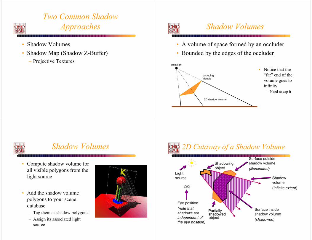
Two Common ShadowApproaches
• Shadow Volumes• Shadow Map (Shadow Z-Buffer)
– Projective Textures
Shadow Volumes
• A volume of space formed by an occluder• Bounded by the edges of the occluder
point light
occluding triangle
3D shadow volume
• Notice that the “far” end of the volume goes to infinity– Need to cap it
Shadow Volumes
• Compute shadow volume for all visible polygons from the light source
• Add the shadow volume polygons to your scene database– Tag them as shadow polygons– Assign its associated light
source
2D Cutaway of a Shadow Volume
Shadowingobject
Partiallyshadowed object
Lightsource
Eye position(note that shadows are independent of the eye position)
Surface insideshadow volume(shadowed)
Surface outsideshadow volume(illuminated)
Shadowvolume(infinite extent)

Shadow Volume Advantages• Omni-directional approach
– Not just spotlight frustums as with shadow maps• Automatic self-shadowing
– Everything can shadow everything, including self– Without shadow acne artifacts as with shadow maps
• Window-space shadow determination– Shadows accurate to a pixel (Object method)– Or sub-pixel if multisampling is available
• Required stencil buffer broadly supported today– OpenGL support since version 1.0 (1991)– Direct3D support since DX6 (1998)
Shadow Volume Disadvantages• Ideal light sources only
– Limited to local point and directional lights– No area light sources for soft shadows
• Requires polygonal models with connectivity– Models must be closed (2-manifold)– Models must be free of non-planar polygons
• Silhouette computations are required– Can burden CPU– Particularly for dynamic scenes
• Inherently multi-pass algorithm• Consumes lots of GPU fill rate
Visualizing Shadow Volumes in 3D
Lightsource
Scene with shadows from an NVIDIA logo casting a
shadow volume
Visualization of the shadow volume
Occluders and light source cast out a shadow volume
Objects within the volume should be shadowed
Visualizing the Stencil Buffer Counts
red = stencil value of 1green = stencil value of 0
Shadowed scene Stencil buffer contents
GLUT shadowvol example credit: Tom McReynolds
Stencil counts beyond 1 are possible for multiple or complex occluders.

Shadow Volumes
• Use a parity test similar to a “ray inside-outside” test
• Initially set parity to 0 and shoot ray from eye to P– Invert parity when ray crosses
shadow volume boundary– parity = 0, not in shadow,
parity = 1, in shadow
point light
eye
occluder
parity=0 parity=1 parity=0
00
0
1
1
0
When is a surface point inside shadow?
Problems With Parity Test
0 0
0
1
Eye inside of shadow volume
Self-shadowing of visible occluders
Multiple overlapping shadow volumes
0
0 1 10 0
Better Solution : Counter
Shadowing objectLightsource
Eyeposition
zero
zero
+1
+1+2 +2
+3
Shadowedobject
Shadow Volume Count = 0
Better Solution : Counter
Shadowing objectLightsource
Eyeposition
zero
zero
+1
+1+2 +2
+3
Shadowedobject
+ -+ +
Shadow Volume Count = +1+1+1-1 = 2

Better Solution : Counter
Shadowing objectLightsource
Eyeposition
zero
zero
+1
+1+2 +2
+3
Unshadowedobject
+ ---+ +
Shadow Volume Count = +1+1+1-1-1-1 = 0
Graphics Hardware Approach Using The Stencil Buffer
• Zpass approach– Render visible scene to depth buffer– Turn off depth and color, turn on stencil– Init. stencil buffer given viewpoint – Draw shadow volume twice using face culling
• 1st pass: render front faces and increment when depth test passes
• 2nd pass: render back faces and decrement when depth test passes
• stencil pixels != 0 in shadow, = 0 are lit
Zpass Problem
zero
zero
+1+1+2
+2+3
Near clipplane
Far clipplane
Missed shadow volume intersection due to near clip plane clipping; leads to mistaken count
Object in shadow :-(
Zfail Approach
– Render visible scene to depth buffer– Turn off depth and color, turn on stencil– Init. stencil buffer given viewpoint– Draw shadow volume twice using face culling
• 1st pass: render back faces and increment when depth test fails
• 2nd pass: render front faces and decrement when depth test fails
– stencil pixels != 0 in shadow, = 0 are lit

Clipping Plane Problem
• Zpass : Near clipping plane– Move near clipping plane closer to eye?
• Lose depth precision in perspective
• Zfail : Far clipping plane– Move far clipping plane closer to eye?
• Set far clipping plane to infinity.• See “Practical & Robust Stenciled Shadow
Volumes for Hardware-Accelerated Rendering” by Cass Everitt & Mark J. Kilgard, Nvidia
Zfail versus Zpass Comparison (1)
When stencil increment/decrements occurZpass: on depth test passZfail: on depth test fail
Increment onZpass: front facesZfail: back faces
Decrement onZpass: front facesZfail: back faces
Zfail versus Zpass Comparison (2)
• Both cases order passes based stencil operation– First, render increment pass– Second, render decrement pass– Why?
• Because standard stencil operations saturate• Wrapping stencil operations can avoid this
• Which clip plane creates a problem– Zpass: near clip plane – Zfail: far clip plane
• Either way is foiled by view frustum clipping– Which clip plane (front or back) changes
Insight!• If we could avoid either near plane or far plane
view frustum clipping, shadow volume rendering could be robust
• Avoiding near plane clipping– Not really possible– Objects can always be behind you– Moreover, depth precision in a perspective view goes to
hell when the near plane is too near the eye • Avoiding far plane clipping
– Perspective make it possible to render at infinity– Depth precision is terrible at infinity, but
we just care about avoiding clipping
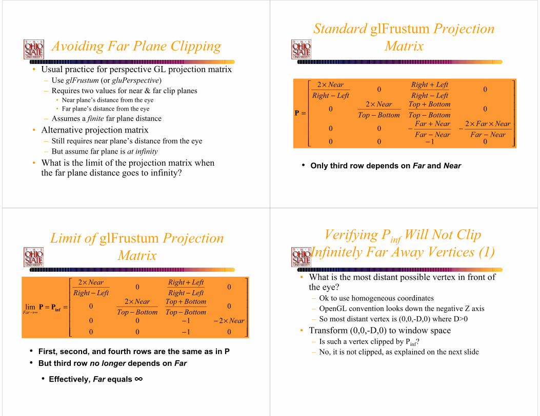
Avoiding Far Plane Clipping• Usual practice for perspective GL projection matrix
– Use glFrustum (or gluPerspective)– Requires two values for near & far clip planes
• Near plane’s distance from the eye• Far plane’s distance from the eye
– Assumes a finite far plane distance• Alternative projection matrix
– Still requires near plane’s distance from the eye– But assume far plane is at infinity
• What is the limit of the projection matrix whenthe far plane distance goes to infinity?
Standard glFrustum Projection Matrix
−−
××−−+−
−+
−×
−+
−×
=
0100
200
020
002
NearFarNearFar
NearFarNearFar
BottomTopBottomTop
BottomTopNear
LeftRightLeftRight
LeftRightNear
P
• Only third row depends on Far and Near
Limit of glFrustum Projection Matrix
−×−−
−+
−×
−+
−×
==∞→
01002100
020
002
lim
NearBottomTopBottomTop
BottomTopNear
LeftRightLeftRight
LeftRightNear
Far infPP
• First, second, and fourth rows are the same as in P• But third row no longer depends on Far
• Effectively, Far equals ∞∞∞∞
Verifying Pinf Will Not ClipInfinitely Far Away Vertices (1)
• What is the most distant possible vertex in front of the eye?– Ok to use homogeneous coordinates– OpenGL convention looks down the negative Z axis– So most distant vertex is (0,0,-D,0) where D>0
• Transform (0,0,-D,0) to window space– Is such a vertex clipped by Pinf?– No, it is not clipped, as explained on the next slide

Verifying Pinf Will Not ClipInfinitely Far Away Vertices (2)
• Transform eye-space (0,0,-D,0) to clip-space
−
−×−−
−+
−×
−+
−×
=
=
−−
0
00
01002100
020
002
DNear
BottomTopBottomTop
BottomTopNear
LeftRightLeftRight
LeftRightNear
wzyx
DD
yx
c
c
c
c
c
c
15.05.05.05.0 =+−−×=+×=
DD
wzz
c
cw
• Then, assuming glDepthRange(0,1), transform clip-space position to window-space position
• So ∞∞∞∞ in front of eye transforms to the maximumwindow-space Z value, but is still withinthe valid depth range (i.e., not clipped)
Is Pinf Bad for Depth Buffer Precision?
• Naïve question– Wouldn’t moving the far clip plane to infinity waste
depth buffer precision? Seems plausible, but• Answer: Not really
– Minimal depth buffer precision is wasted in practice– This is due to projective nature of perspective
• Say Near is 1.0 and Far is 100.0 (typical situation)– P would transform eye-space infinity to only 1.01 in
window space– Only a 1% compression of the depth range
is required to render infinity without clipping– Moving near closer would hurt precision
Pinf Depth Precision Scale Factor• Using Pinf with Near instead of P with Near and
Far compresses (scales) the depth precision by
FarNearFar )( −
• The compression of depth precision is uniform, but the depth precision itself is already non-uniform on eye-space interval [Near,Far] due to perspective• So the discrete loss of precision is more towards the far clip
plane
• Normally, Far >> Near so the scale factoris usually less than but still nearly 1.0• So the compression effect is minor
Without Near (or Far) Plane Capping• Use Zfail Stenciling Approach
– Must render geometry to close shadow volume extrusion on the model and at infinity (explained later)
• Use the Pinf Projection Matrix– No worries about far plane clipping– Losses some depth buffer precision (but not much)
• Draw the infinite vertices of the shadow volume using homogeneous coordinates (w=0)
Robust Stenciled Shadow Volumes

Rendering Closed, but Infinite,Shadow Volumes
• To be robust, the shadow volume geometry must be closed, even at infinity
• Three sets of polygons close the shadow volume1. Possible silhouette edges extruded to infinity away from
the light2. All of the occluder’s back-facing (w.r.t. the light)
triangles projected away from the light to infinity3. All of the occluder’s front-facing (w.r.t. the light)
triangles• We assume the object vertices and light position
are homogeneous coordinates, i.e. (x,y,z,w)– Where w≥0
1st Set of Shadow Volume Polygons
• Assuming– A and B are vertices of an occluder model’s possible
silhouette edge– And L is the light position
• For all A and B on silhouette edges of the occluder model, render the quad
0,,,0,,,
,,,,,,
wzwzwywywxwx
wzwzwywywxwx
wzyx
wzyx
BLLBBLLBBLLBALLAALLAALLA
AAAABBBB
−−−−−−
• What is a possible silhouette edge?• One polygon sharing an edge faces toward L• Other faces away from L
Homogenous vector differences
Examples Silhouette Edges
An object viewed from the same basic direction that the light is shining on the object has an identifiable light-view silhouette
An object’s light-view silhouette appears quite jumbled when viewed form a point-of-view that does not correspond well with the light’s point-of-view
2nd and 3rd Set ofShadow Volume Polygons
• 2nd set of polygons– Assuming A, B, and C are each vertices of occluder
model’s back-facing triangles w.r.t. light position L
0,,,0,,,0,,,
wzwzwywywxwx
wzwzwywywxwx
wzwzwywywxwx
CLLCCLLCCLLCBLLBBLLBBLLBALLAALLAALLA
−−−−−−−−−
• These vertices are effectively directions (w=0)• 3rd set of polygons
• Assuming A, B, and C are each vertices of occluder model’s front-facing triangles w.r.t. light position L
wzyx
wzyx
wzyx
CCCCBBBBAAAA
,,,,,,,,,
Homogenous vector differences

Requirements for StenciledShadow Volumes
1. Models must be composed of triangles only (avoiding non-planar polygons)
2. Models must be closed (2-manifold) and have a consistent winding order– Bergeron [’86] approach could be used to handle “open”
models if necessary3. Homogeneous object coordinates are permitted,
assuming w≥0– If not, (x, y, z, -1) = (-x, -y, -z, 1)
4. Ideal light sources only– Directional or positional, assuming w≥0
Requirements for Stenciled Shadow Volumes
5. Connectivity information for occluding models must be available– So silhouette edges w.r.t. light positions can be
determined at shadow volume construction time6. Projection matrix must be perspective
– Not orthographic– NV_depth_clamp extension provides orthographic
support (more later)7. Render must guarantee “watertight” rasterization
– No double hitting pixels at shared polygon edges– No missed pixels at shared polygon edges
Requirements for Stenciled Shadow Volumes
8. Enough stencil bits– N stencil bits where 2N is greater than the maximum
shadow depth count ever encountered– Scene dependent– 8-bits is usually quite adequate & what all recent stencil
hardware provides– Wrapping stencil increment/decrement operations (i.e.
OpenGL’s EXT_stencil_wrap) permit deeper shadow counts, modulo aliasing with zero
– Realize that shadow depths > 255 imply toomuch fill rate for interactive applications
Requirements for Stenciled Shadow Volumes
9. Rendering features provided by OpenGL 1.0 or DirectX 6 (or subsequent versions)– Transformation & clipping of homogenous positions– Front- and back-face culling– Masking color and depth buffer writes– Depth buffering (i.e. conventional Z-buffering)– Stencil-testing support
In practice, these are quite reasonable requirements for nearly any polygonal-based 3D game or application

Examples
Scene with shadows.Yellow light is embedded in the green three-holed object. Pinf is used for all the following scenes.
Same scene visualizingthe shadow volumes.
ExamplesDetails worth noting . . .
Fine details: Shadowsof the A, N, and T letters onthe knight’s armor and shield.
Hard case: The shadow volume from the front-facing holewould definitely intersectthe near clip plane.
Examples
Alternate view of same scene with shadows. Yellow lines indicate previous view’s view frustum boundary. Recall shadows are view-independent.
Shadow volumes from the alternate view.
Examples
Clip-space view. Original view’s scene seen from clip space. The back plane is “at infinity” with very little effective depth precision near infinity.
Clip-space view of shadow volumes. Back-facingtriangles w.r.t. light are seenprojected onto farplane at infinity.
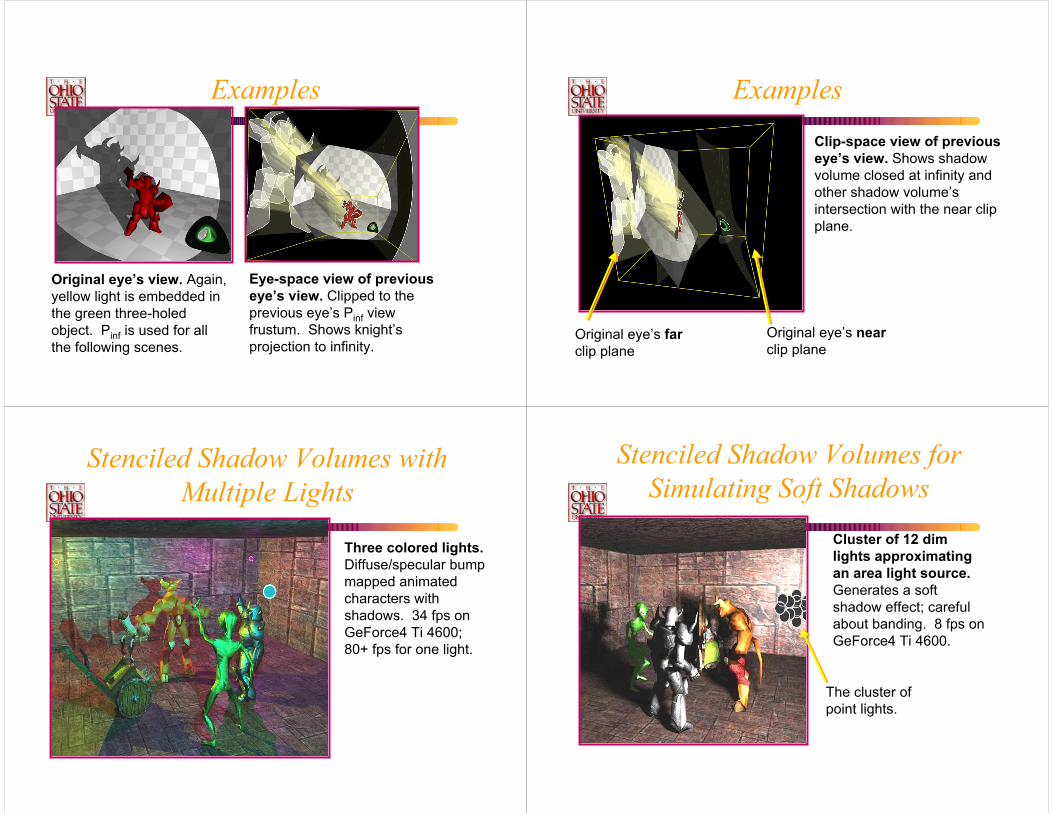
Examples
Original eye’s view. Again, yellow light is embedded in the green three-holed object. Pinf is used for all the following scenes.
Eye-space view of previous eye’s view. Clipped to the previous eye’s Pinf viewfrustum. Shows knight’sprojection to infinity.
Examples
Clip-space view of previous eye’s view. Shows shadow volume closed at infinity and other shadow volume’s intersection with the near clip plane.
Original eye’s farclip plane
Original eye’s nearclip plane
Stenciled Shadow Volumes withMultiple Lights
Three colored lights. Diffuse/specular bump mapped animated characters with shadows. 34 fps on GeForce4 Ti 4600;80+ fps for one light.
Stenciled Shadow Volumes forSimulating Soft Shadows
Cluster of 12 dim lights approximating an area light source. Generates a soft shadow effect; careful about banding. 8 fps on GeForce4 Ti 4600.
The cluster of point lights.

Issues With Shadow Volumes
• The addition of shadow volume polygons can greatly increase your database size
• Using the stencil buffer approach, pixel fill becomes a key speed factor
• Create a shadow volume from the silhouette of an object instead of each polygon
• Take care when coding the algorithm
Hardware Enhancements:Wrapping Stencil Operations
• Conventional OpenGL 1.0 stencil operations– GL_INCR increments and clamps to 2N-1– GL_DECR decrements and clamps to zero
• DirectX 6 introduced “wrapping” stencil operations• Exposed by OpenGL’s EXT_stencil_wrap
extension– GL_INCR_WRAP_EXT increments modulo 2N
– GL_DECR_WRAP_EXT decrements modulo 2N
• Avoids saturation throwing off the shadowvolume depth count– Still possible, though very rare, that 2N,
2×2N, 3×2N, etc. can alias to zero
Hardware Enhancements:Two-sided Stencil Testing (1)
• Current stenciled shadow volumes required rendering shadow volume geometry twice– First, rasterizing front-facing geometry– Second, rasterizing back-facing geometry
• Two-sided stencil testing requires only one pass– Two sets of stencil state: front- and back-facing– Boolean enable for two-sided stencil testing– When enabled, back-facing stencil state is used for stencil
testing back-facing polygons– Otherwise, front-facing stencil state is used– Rasterizes just as many fragments,
but more efficient for CPU & GPU
Hardware Enhancements:Two-sided Stencil Testing (2)
NV_stencil_two_side OpenGL extension– Enable applies if GL_STENCIL_TEST also enabled
glEnable(GL_STENCIL_TEST_TWO_SIDE_NV);glDisable(GL_STENCIL_TEST_TWO_SIDE_NV);
– Control of front- and back-facing stencil state updateglActiveStencilFaceNV(GL_FRONT);glActiveStencilFaceNV(GL_BACK);
– Existing stencil routines (glStencilOp, glStencilMask, glStencilFunc) update the active stencil face state
– glClear and non-polygon primitives alwaysuse the front-facing stencil state
• Expect on future GPUs

Usage of NV_stencil_two_side & EXT_stencil_wrap
OLD SCHOOLglDepthMask(0);glColorMask(0,0,0,0);glEnable(GL_CULL_FACE);glEnable(GL_STENCIL_TEST);glStencilMask(~0);glStencilFunc(GL_ALWAYS, 0, ~0);// Increment for back faces
glCullFace(GL_BACK);glStencilOp(GL_KEEP, // stencil test fail
GL_INCR, // depth test failGL_INCR); // depth test pass
renderShadowVolumePolygons();// Decrement for front facesglCullFace(GL_FRONT);glStencilOp(GL_KEEP, // stencil test fail
GL_DECR, // depth test failGL_KEEP); // depth test pass
renderShadowVolumePolygons();
NEW SCHOOLglDepthMask(0);glColorMask(0,0,0,0);glDisable(GL_CULL_FACE);glEnable(GL_STENCIL_TEST);glEnable(GL_STENCIL_TEST_TWO_SIDE_NV);glActiveStencilFaceNV(GL_BACK);glStencilOp(GL_KEEP, // stencil test fail
GL_INCR_WRAP_EXT, // depth test fail GL_KEEP); // depth test pass
glStencilMask(~0);glStencilFunc(GL_ALWAYS, 0, ~0);glActiveStencilFaceNV(GL_FRONT);glStencilOp(GL_KEEP, // stencil test fail
GL_DECR_WRAP_EXT, // depth test failGL_KEEP); // depth test pass
glStencilMask(~0);glStencilFunc(GL_ALWAYS, 0, ~0);renderShadowVolumePolygons();
New approach calls renderShadowVolumePolygons() just once.
Shadow Volume History (1)• Invented by Frank Crow [’77]
– Software rendering scan-line approach• Brotman and Badler [’84]
– Software-based depth-buffered approach– Used lots of point lights to simulate soft shadows
• Pixel-Planes [Fuchs, et.al. ’85] hardware– First hardware approach– Point within a volume, rather than ray intersection
• Bergeron [’96] generalizations– Explains how to handle open models– And non-planar polygons
Shadow Volume History (2)• Fournier & Fussell [’88] theory
– Provides theory for shadow volume counting approach within a frame buffer
• Akeley & Foran invent the stencil buffer– IRIS GL functionality, later made part of OpenGL 1.0– Patent filed in ’92
• Heidmann [IRIS Universe article, ’91]– IRIS GL stencil buffer-based approach
• Deifenbach’s thesis [’96]– Used stenciled volumes in multi-pass framework
Shadow Volume History (3)• Dietrich slides [March ’99] at GDC
– Proposes zfail based stenciled shadow volumes• Kilgard whitepaper [March ’99] at GDC
– Invert approach for planar cut-outs• Bilodeau slides [May ’99] at Creative seminar
– Proposes way around near plane clipping problems– Reverses depth test function to reverse stencil volume ray
intersection sense• Carmack [unpublished, early 2000]
– First detailed discussion of the equivalence ofzpass and zfail stenciled shadowvolume methods

Shadow Volume History (4)• Kilgard [2001] at GDC and CEDEC Japan
– Proposes zpass capping scheme• Project back-facing (w.r.t. light) geometry to the near clip plane
for capping• Establishes near plane ledge for crack-free
near plane capping– Applies homogeneous coordinates (w=0) for rendering
infinite shadow volume geometry• Cass and Kilgard [2001] presented most of these
slides at GDC. See their papers on the nVidia web site.
• Carmack’s Doom engine uses this technique.
Shadow Maps
• Basic Theory• Several Implementations
– Hardware shadow maps– Multi-texturing and shadow maps– Object buffers
Z-Buffer Shadow Maps
• Define a coordinate system (light space) such that the light is the center of projection
• Render a depth buffer (z-buffer) of the visible scene, each pixel (x’, y’, z’)
• For each visible surface point in eye space transform to light space– (xc, yc, zc) => (xl, yl, zl)
• If zl > z’ then point is in shadow
Shadow Map
• Visible surface point E is in shadow and occluded by point L when transformed to light space
Light
Eye
Eye-ray nearest intersection point
Light-ray nearest intersection point
L
E
If L is closer to the light than E, then E is in shadow

Shadow Map : Two Pass Approach 1st Pass
View from light Depth Buffer
2nd Pass
Visible surface depth
2nd Pass
Non-green in shadow Final Image

Shadow Maps With Graphics Hardware
• Render scene using the light as a camera• Read depth buffer out and copy to a 2D texture.
– Rather than Binary projected shadow, we now have a depth texture.
• Fragment’s light position can be generated using eye-linear texture coordinate generation
• specifically OpenGL’s GL_EYE_LINEAR texgen• generate homogenous (s, t, r, q) texture coordinates as light-
space (x, y, z, w)
Introducing Another Technique:Shadow Mapping
• Image-space shadow determination– Lance Williams published the basic idea in 1978
• By coincidence, same year Jim Blinn invented bump mapping (a great vintage year for graphics)
– Completely image-space algorithm• means no knowledge of scene’s geometry is required• must deal with aliasing artifacts
– Well known software rendering technique• Pixar’s RenderMan uses the algorithm• Basic shadowing technique for Toy Story, etc.
Shadow MappingReferences
• Important SIGGRAPH papers– Lance Williams, “Casting Curved Shadows on Curved
Surfaces,” SIGGRAPH 78– William Reeves, David Salesin, and Robert Cook
(Pixar), “Rendering antialiased shadows with depth maps,” SIGGRAPH 87
– Mark Segal, et. al. (SGI), “Fast Shadows and Lighting Effects Using Texture Mapping,” SIGGRAPH 92
The Shadow MappingConcept (1)
• Depth testing from the light’s point-of-view– Two pass algorithm– First, render depth buffer from the light’s point-of-view
• the result is a “depth map” or “shadow map”• essentially a 2D function indicating the depth of the
closest pixels to the light– This depth map is used in the second pass

The Shadow MappingConcept (2)
• Shadow determination with the depth map– Second, render scene from the eye’s point-of-view– For each rasterized fragment
• determine fragment’s XYZ position relative to the light• this light position should be setup to match the frustum
used to create the depth map• compare the depth value at light position XY in the depth
map to fragment’s light position Z
The Shadow MappingConcept (3)
• The Shadow Map Comparison– Two values
• A = Z value from depth map at fragment’s light XY position• B = Z value of fragment’s XYZ light position
– If B is greater than A, then there must be something closer to the light than the fragment
• then the fragment is shadowed
– If A and B are approximately equal, the fragment is lit
Shadow Mappingwith a Picture in 2D (1)
lightsource
eyeposition
depth map Z = A
fragment’slight Z = B
depth map image plane
eye view image plane,a.k.a. the frame buffer
The A < B shadowed fragment case
Shadow Mappingwith a Picture in 2D (2)
lightsource
eyeposition
depth map Z = A
fragment’slight Z = B
depth map image plane
eye view image plane,a.k.a. the frame buffer
The A ≅≅≅≅ B unshadowed fragment caseThe A ≅≅≅≅ B unshadowed fragment case
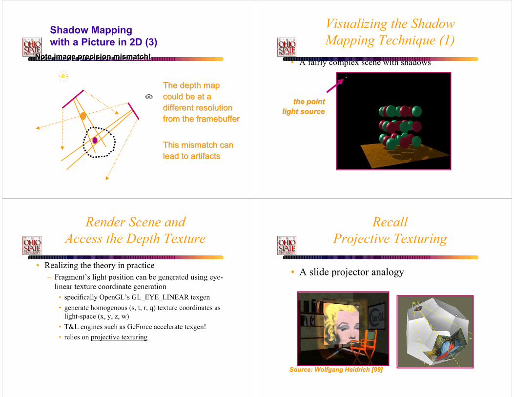
Note image precision mismatch!Note image precision mismatch!
The depth mapThe depth mapcould be at acould be at adifferent resolutiondifferent resolutionfrom the framebufferfrom the framebuffer
This mismatch canThis mismatch canlead to artifactslead to artifacts
Shadow Mappingwith a Picture in 2D (3)
Visualizing the ShadowMapping Technique (1)
• A fairly complex scene with shadows
the pointthe pointlight sourcelight source
Render Scene andAccess the Depth Texture
• Realizing the theory in practice– Fragment’s light position can be generated using eye-
linear texture coordinate generation• specifically OpenGL’s GL_EYE_LINEAR texgen• generate homogenous (s, t, r, q) texture coordinates as
light-space (x, y, z, w)• T&L engines such as GeForce accelerate texgen!• relies on projective texturing
RecallProjective Texturing
• A slide projector analogy
Source: Wolfgang Heidrich [99]Source: Wolfgang Heidrich [99]

Projective Texture Shadows
Light’s point-of-view Shadow projective texture (modulation image or light-map)
Eye’s point-of-view, projective texture
applied to ground-plane(self-shadowing is from
another algorithm)
Projective Texture Shadows
Two-pass approach• For each light source:
– Create a light camera that encloses shadowed area– Render shadow casting objects into light’s view
only need to create a light map (1 in light, 0 in shadow)
– Create projective texture from light’s view– Render fully-lit shadow receiving objects with applied
modulation projective-textures (need additive blending for all light sources except first one)
• Render fully-lit shadow casting objects
Perspective-Correct Texturing
• First, what is perspective-correct texturing?– Normal 2D texture mapping uses (s, t) coordinates– 2D perspective-correct texture mapping
• means (s, t) should be interpolated linearly in eye-space• so compute per-vertex s/w, t/w, and 1/w• linearly interpolate these three parameters over polygon• per-fragment compute s’ = (s/w) / (1/w) and t’ = (t/w) /
(1/w)• results in per-fragment perspective correct (s’, t’)
Projective Texturing
• So what is projective texturing?– Now consider homogeneous texture coordinates
• (s, t, r, q) --> (s/q, t/q, r/q)• Similar to homogeneous clip coordinates where
(x, y, z, w) = (x/w, y/w, z/w)– Idea is to have (s/q, t/q, r/q) be projected per-fragment– This requires a per-fragment divider
• yikes, dividers in hardware are fairly expensive

Projective Texturing
• Hardware designer’s view of texturing– Perspective-correct texturing is a practical requirement
• otherwise, textures “swim”• perspective-correct texturing already requires the
hardware expense of a per-fragment divider– Clever idea [Segal, et.al. ‘92]
• interpolate q/w instead of simply 1/w• so projective texturing is practically free if you already
do perspective-correct texturing!
Projective Texturing
• Tricking hardware into doing projective textures– By interpolating q/w, hardware computes per-fragment
• (s/w) / (q/w) = s/q• (t/w) / (q/w) = t/q
– Net result: projective texturing• OpenGL specifies projective texturing• only overhead is multiplying 1/w by q• but this is per-vertex
Projected Shadow Maps
• Assign light-space texture coordinates via texgen– Transform eye-space (x, y, z, w) coordinates to the
light’s view frustum (match how the light’s depth map is generated)
– Further transform these coordinates to map directly into the light view’s depth map
– Expressible as a projective transform• load this transform into the 4 eye linear plane equations for S,
T, and Q coordinates
– (s/q, t/q) will map to light’s depth map texture
OpenGL’s StandardVertex Coordinate Transform
• From object coordinates to window coordinates
object
coordinates(x, y, z, w)
objectobject
coordinatescoordinates(x, y, z, w)(x, y, z, w)
eye
coordinates(x, y, z, w)
eyeeye
coordinatescoordinates(x, y, z, w)(x, y, z, w)
modelviewmatrix
modelviewmodelviewmatrixmatrix
projectionmatrix
projectionprojectionmatrixmatrix
divideby w
dividedivideby wby w
viewport &depth rangeviewport &viewport &
depth rangedepth rangenormalized
devicecoordinates
(x, y, z)
normalized normalized
devicedevicecoordinatescoordinates
(x, y, z)(x, y, z)
clip
coordinates(x, y, z, w)
clipclip
coordinatescoordinates(x, y, z, w)(x, y, z, w)
window
coordinates
windowwindow
coordinatescoordinatesonward toprimitiveassembly
onward toonward toprimitiveprimitiveassemblyassembly
(x, y, z)(x, y, z)(x, y, z)

Eye Linear TextureCoordinate Generation
• Generating texture coordinates from eye-space
object
coordinates
objectobject
coordinatescoordinates
eye
coordinates
eyeeye
coordinatescoordinatesmodelview
matrixmodelviewmodelview
matrixmatrixprojection
matrixprojectionprojection
matrixmatrix
divideby w
dividedivideby wby w
viewport &depth rangeviewport &viewport &
depth rangedepth rangenormalized
devicecoordinates
normalized normalized
devicedevicecoordinatescoordinates
clip
coordinates
clipclip
coordinatescoordinates
window
coordinates
windowwindow
coordinatescoordinates
eye-linearplane
equations
eyeeye--linearlinearplaneplane
equationsequations(s, t, r, q)(s, t, (s, t, rr, q), q)
(x, y, z)(x, y, z)(x, y, z)
Setting UpEye Linear Texgen
•With OpenGL– GLfloat Splane[4], Tplane[4], Rplane[4], Qplane[4];– glTexGenfv(GL_S, GL_EYE_PLANE, Splane);– glTexGenfv(GL_T, GL_EYE_PLANE, Tplane);– glTexGenfv(GL_R, GL_EYE_PLANE, Rplane);– glTexGenfv(GL_Q, GL_EYE_PLANE, Qplane);– glEnable(GL_TEXTURE_GEN_S);– glEnable(GL_TEXTURE_GEN_T);– glEnable(GL_TEXTURE_GEN_R);– glEnable(GL_TEXTURE_GEN_Q);
•Each plane equation is transformed by current inverse modelview matrix (a very handy thing for us)
Eye LinearTexgen Transform
• Plane equations form a projective transform
• The 4 eye linear plane equations form a 4x4 matrix(No need for the texture matrix!)
strq
ssttrrqq
Splane[0] Splane[1] Splane[2] Splane[3]Splane[0] Splane[1] Splane[0] Splane[1] Splane[2] Splane[2] Splane[3]Splane[3]
Tplane[0] Tplane[1] Tplane[2] Tplane[3]Tplane[0] Tplane[1] Tplane[2] Tplane[3]Tplane[0] Tplane[1] Tplane[2] Tplane[3]
Rplane[0] Rplane[1] Rplane[2] Rplane[3]Rplane[0] Rplane[0] Rplane[1] Rplane[2] Rplane[1] Rplane[2] Rplane[3]Rplane[3]
Qplane[0] Qplane[1] Qplane[2] Qplane[3]Qplane[0] Qplane[1] Qplane[2] Qplane[3]Qplane[0] Qplane[1] Qplane[2] Qplane[3]
===xeyezewe
xxeeyyeezzeewwee
Shadow Map Eye LinearTexgen Transform
1/21/21/2
1/21/21/2
1/21/21/2
111
1/21/21/2
1/21/21/2
1/21/21/2Light
frustum(projection)
matrix
LightLightfrustumfrustum
(projection)(projection)matrixmatrix
Lightview
(look at)matrix
LightLightviewview
(look at)(look at)matrixmatrix
Inverseeyeview
(look at)matrix
InverseInverseeyeeyeviewview
(look at)(look at)matrixmatrix
Eyeview
(look at)matrix
EyeEyeviewview
(look at)(look at)matrixmatrix
Modelingmatrix
ModelingModelingmatrixmatrix
xoyozowo
xxooyyoozzoowwoo
xeyezewe
xxeeyyeezzeewwee
===
===xeyezewe
xxeeyyeezzeewwee
strq
ssttrrqq
glTexGen automatically applies this when modelview matrix contains just the eye view
transform
glTexGen automatically applies glTexGen automatically applies this when modelview matrix this when modelview matrix contains just the eye view contains just the eye view
transformtransform
Supply this combined transform to glTexGenSupply this combined transform to glTexGenSupply this combined transform to glTexGen

Shadow Map Operation
• Automatic depth map lookups– After the eye linear texgen with the proper transform
loaded • (s/q, t/q) is the fragment’s corresponding location within
the light’s depth texture• r/q is the Z planar distance of the fragment relative to the
light’s frustum, scaled and biased to [0,1] range– Next compare texture value at (s/q, t/q) to value r/q
• if texture[s/q, t/q] ≅ r/q then not shadowed• if texture[s/q, t/q] < r/q then shadowed
Shadow Map Construction
– Set up your view matrix to be the light’s “LookAt” matrix
– Set up the projection matrix based on the light type
• For spotlights, use the penumbra angle for the FOV• For directional lights, use an orthographic projection• For point lights, use a cubemap
– And render once for each face with a 90 degree FOV
Shadow Map Construction
– Render your depth value into the texture• As an Alpha or Color Value
– 0 means at the light plane– FF means at the edge of the light’s range
• Or into the depth buffer– Extract it with glReadPixels– Extract with new extensions (more later)– Map it into a hi-precision texture.
Dedicated HardwareShadow Mapping Support
• SGI RealityEngine, InfiniteReality, and GeForce3 Hardware– Performs the shadow test as a texture filtering operation
• looks up texel at (s/q, t/q) in a 2D texture• compares lookup value to r/q• if texel is greater than or equal to r/q, then generate 1.0• if texel is less than r/q, then generate 0.0
– Modulate color with result• zero if fragment is shadowed or unchanged color if not

OpenGL Extensions forShadow Map Hardware
• Two extensions work together– SGIX_depth_texture
• supports high-precision depth texture formats• copy from depth buffer to texture memory supported
– SGIX_shadow• adds “shadow comparison” texture filtering mode• compares r/q to texel value at (s/q, t/q)
– Multi-vendor support: SGI, NVIDIA, others?• Brian Paul has implemented these extensions in Mesa!
New Depth TextureInternal Texture Formats
• SGIX_depth_texture supports textures containing depth values for shadow mapping
• Three new internal formats– GL_DEPTH_COMPONENT16_SGIX– GL_DEPTH_COMPONENT24_SGIX– GL_DEPTH_COMPONENT32_SGIX
(same as 24-bit on GeForce3)• Use GL_DEPTH_COMPONENT for your external format• Work with glCopySubTexImage2D for fast copies from depth
buffer to texture– NVIDIA optimizes these copy texture paths
Depth Texture Details
• Usage example:glCopyTexImage2D(GL_TEXTURE_2D,level=0,
internalfmt=GL_DEPTH_COMPONENT24_SGIX,
x=0, y=0, w=256, h=256, border=0);
• Then use glCopyTexSubImage2D for faster updates once texture internal format initially defined
Depth Texture Details
• Hint: use GL_DEPTH_COMPONENT for your texture internal format– Leaving off the “n_SGIX” precision specifier
tells the driver to match your depth buffer’s precision
– Copy texture performance is optimum when depth buffer precision matches the depth texture precision

Texture Copy Performance
• The more depth values you copy, the slower the performance– 512x512 takes 4 times longer to copy than 256x256– Tradeoff: better defined shadows require higher
resolution shadow maps, but slows copying• 16-bit depth values copy twice as fast as 24-bit
depth values (which are contained in 32-bit words)– Requesting a 16-bit depth buffer (even with 32-bit color
buffer) and copying to a 16-bit depth texture is faster than using a 24-bit depth buffer
– Note that using 16-bit depth buffer usuallyrequires giving up stencil
Issues With Shadow Maps
• Compute shadow maps for all light sources• Need space to store shadow maps• How do you filter the shadow map when
indexing into it?• Does a mismatch in shadow map resolution
and screen resolution matter?
Shadow-Maps
Depth Sampling Problems
Can we just use the nearest sample?
How would you anti-alias depth?
What is we move closer to the reciever?– Opposite problem
Shadow-MapsDepth sampling: normal filtering
• Averaging depth doesn’t really make sense (unrelated to surface, especially at shadow boundaries!)
• Still a binary result, (no anti-aliased softer shadows)

Depth Values are not Blend-able• Traditional filtering is inappropriate
eyeposition
What pixel covers inshadow map texture
Texel sampledepth = 0.25
Texel sampledepth = 0.63
0.63
0.25 0.25
0.63
Average(0.25, 0.25, 0.63, 0.63) = 0.440.57 > 0.44 so pixel is wrongly “in shadow”Truth: nothing is at 0.44, just 0.25 and 0.63
Pixel depth = 0.57
Shadow-MapsDepth sampling: percentage closer filtering
(Reeves87)
• Could average binary results of all depth map pixels covered
• Soft anti-aliased shadows• Very similar to point-sampling across an area light
source in ray-traced shadow computation
Shadow-MapsHow do you choose the samples?
Quadrilateral represents the area covered by a pixel’s projection onto a polygon after being projected into the shadow-map
Hardware ShadowMap Filtering
• “Percentage Closer” filtering– Provides anti-aliasing at shadow map edges
• Not soft shadows in the umbra/penumbra sense
• Does not do full filtering– Will lead to aliasing for picket-fence shadows.

Hardware Shadow MapFiltering Example
GL_NEAREST: blocky GL_LINEAR: antialiased edges
Low shadow map resolutionused to heighten filtering artifacts
Issues with Shadow Mapping
• Not without its problems– Prone to aliasing artifacts
• “percentage closer” filtering helps this• normal color filtering does not work well
– Depth bias is not completely foolproof– Requires extra shadow map rendering pass and texture
loading– Higher resolution shadow map reduces blockiness
• but also increases texture copying expense
Issues with Shadow Mapping
• Not without its problems– Shadows are limited to view frustums
• could use six view frustums for omni-directional light– Objects outside or crossing the near and far clip planes
are not properly accounted for by shadowing• move near plane in as close as possible• but too close throws away valuable depth map precision
when using a projective frustum
Shadow Map Resolutions
• Requires knowing how pixels (samples) in the light’s view compare to the size of pixels (samples) in the eye’s view– A re-sampling problem
• When light source frustum is reasonably well aligned with the eye’s view frustum, the ratio of sample sizes is close to 1.0– Great match if eye and light frustum’s are nearly
identical– But that implies very few viewable shadows– Consider a miner’s lamp (i.e., a light attached to your
helmet)– The chief reason for such a lamp is you don’t see
shadows from the lamp while wearing it

Shadow Map Resolution
• So best case is miner’s lamp• Worst case is shadows from light shining at the
viewer– “that deer in the headlights” problem – definitely worst
case for the deer– Also known as the “dueling frusta” problem
(frusta, plural of frustum)• Let’s attempt to visualize what happens…
Dueling Frusta Case
Eye’sView
Light’sView
Eye’s View with projectionof color-codedmipmap levelsfrom light:Blue = magnificationRed = minification
Light’s View withre-projectionof above imagefrom the eye
Dueling Frusta Case
Eye’sView
Light’sView
Region that is smallest in the light’s view is a region that is very large in the eye’s view. This implies that it would require a very high-resolution shadow map to avoid obvious blocky shadow edge artifacts.
Dueling Frusta
Light position out here pointing towards the viewer.
Blocky shadow edge artifacts.
Notice that shadow edge is well defined in the distance.

Good Situation, Close to the Miner’s Lamp
Eye’sView
Light’sView
Very similar views
Note how the color-coded images share similar pattern and the coloration is uniform. Implies single depth map resolution would work well for most of the scene.
Ghosting is where projection would be in shadow.
More Examples• Smooth surfaces with object self-shadowing
Note object self-shadowing
More Examples
• Complex objects all shadow
More Examples
• Even the floor casts shadowNote shadow leakage due toinfinitely thin floor
Could be fixed bygiving floor thickness

Projective Texturingfor Spotlight Shadows
• Use a spotlight-style projected texture to give shadow maps a spotlight falloff.
Multi-texturing Shadow Maps
• Consumer 3D hardware solution– Proposed by Wolfgang Heidrich in his 1999 Ph.D.
thesis– Leverages today’s consumer multi-texture hardware
• 1st texture unit accesses 2D depth map texture• 2nd texture unit accesses 1D Z range texture
– Extended texture environment subtracts 2nd texture from 1st
• shadowed if greater than zero, unshadowed otherwise• use alpha test to discard shadowed fragments
Dual-texture ShadowMapping Approach
• Constructing the depth map texture– Render scene from the light view (can disable
color writes)– Use projective textures and a shadow map as
before.
Dual-texture ShadowMapping Approach
• Two-pass shadow determination– 1st pass: draw everything shadowed
• render scene with light disabled -or- dimmed substantially and specular light color of zero
• with depth testing enabled
– 2nd pass: draw unshadowed, rejecting shadowed fragments
• use glDepthFunc(GL_EQUAL) to match 1st pass pixels• enable the light source, un-rejected pixels = unshadowed• use dual-texture as described in subsequent slides

Dual-texture ShadowMapping Approach
• Dual-texture configuration– 1st texture unit
• bind to 2D texture containing light’s depth map texture• intensity texture format (same value in RGB and alpha)
– 2nd texture unit• bind to 1D texture containing a linear ramp from 0 to 1• maps S texture coordinate in [0, 1] range to intensity value in
[0, 1] range
Dual-texture ShadowMapping Approach
• Texgen Configuration– 1st texture unit using 2D texture
• generate (s/q, t/q) to access depth map texture, ignore R
1/21/21/2
1/21/21/2
111
1/21/21/2
1/21/21/2Light
frustum(projection)
matrix
LightLightfrustumfrustum
(projection)(projection)matrixmatrix
Lightview
(look at)matrix
LightLightviewview
(look at)(look at)matrixmatrix
Inverseeyeview
(look at)matrix
InverseInverseeyeeyeviewview
(look at)(look at)matrixmatrix
===xeyezewe
xxeeyyeezzeewwee
st
q
sstt
Supply this combined transform to glTexGenSupply this combined transform to glTexGenSupply this combined transform to glTexGenglTexGen
automaticallyapplies this
glTexGenglTexGenautomaticallyautomaticallyapplies thisapplies this
Dual-texture ShadowMapping Approach
• Texgen Configuration– 2nd texture unit using 1D texture
• generate Z planar distance in S, flips what R is into S
1/21/21/2
1/21/21/2
111
1/21/21/2
1/21/21/2Light
frustum(projection)
matrix
LightLightfrustumfrustum
(projection)(projection)matrixmatrix
Lightview
(look at)matrix
LightLightviewview
(look at)(look at)matrixmatrix
Inverseeyeview
(look at)matrix
InverseInverseeyeeyeviewview
(look at)(look at)matrixmatrix
===xeyezewe
xxeeyyeezzeewwee
s
q
ss
Supply this combined transform to glTexGenSupply this combined transform to glTexGenSupply this combined transform to glTexGenglTexGen
automaticallyapplies this
glTexGenglTexGenautomaticallyautomaticallyapplies thisapplies this
0 0 1 00 0 1 00 0 1 0
1111/21/21/21/21/21/2
Dual-texture ShadowMapping Approach
• Texture environment (texenv) configuration– Compute the difference between Tex0 from Tex1
• un-extended OpenGL texenv cannot subtract
– But can use standard EXT_texture_env_combineextension
• add signed operation• compute fragment alpha as
alpha(Tex0) + (1 - alpha(Tex1)) - 0.5• result is greater or equal to 0.5 when Tex0 >= Tex1
result is less than 0.5 when Tex0 < Tex1

Dual-texture ShadowMapping Approach
•Texture environment (texenv) specifics•glActiveTextureARB(GL_TEXTURE0_ARB);•glTexEnvi(GL_TEXTURE_ENV, GL_TEXTURE_ENV_MODE, GL_COMBINE_EXT);
•glTexEnvi(GL_TEXTURE_ENV, GL_COMBINE_RGB_EXT, GL_REPLACE);•glTexEnvi(GL_TEXTURE_ENV, GL_SOURCE0_RGB_EXT, GL_PRIMARY_COLOR_EXT);•glTexEnvi(GL_TEXTURE_ENV, GL_OPERAND0_RGB_EXT, GL_SRC_COLOR);
•glTexEnvi(GL_TEXTURE_ENV, GL_COMBINE_ALPHA_EXT, GL_REPLACE);•glTexEnvi(GL_TEXTURE_ENV, GL_SOURCE0_ALPHA_EXT, GL_TEXTURE);•glTexEnvi(GL_TEXTURE_ENV, GL_OPERAND0_ALPHA_EXT, GL_SRC_ALPHA);
•glActiveTextureARB(GL_TEXTURE1_ARB);•glTexEnvi(GL_TEXTURE_ENV, GL_TEXTURE_ENV_MODE, GL_COMBINE_EXT);
•glTexEnvi(GL_TEXTURE_ENV, GL_COMBINE_RGB_EXT, GL_REPLACE);•glTexEnvi(GL_TEXTURE_ENV, GL_SOURCE0_RGB_EXT, GL_PREVIOUS_EXT);•glTexEnvi(GL_TEXTURE_ENV, GL_OPERAND0_RGB_EXT, GL_SRC_COLOR);
•glTexEnvi(GL_TEXTURE_ENV, GL_COMBINE_ALPHA_EXT, GL_ADD_SIGNED_EXT);•glTexEnvi(GL_TEXTURE_ENV, GL_SOURCE0_ALPHA_EXT, GL_PREVIOUS_EXT);•glTexEnvi(GL_TEXTURE_ENV, GL_OPERAND0_ALPHA_EXT, GL_SRC_ALPHA);•glTexEnvi(GL_TEXTURE_ENV, GL_SOURCE1_ALPHA_EXT, GL_TEXTURE);•glTexEnvi(GL_TEXTURE_ENV, GL_OPERAND1_ALPHA_EXT, GL_ONE_MINUS_SRC_ALPHA);
Dual-texture ShadowMapping Approach
• Post-texture environment result– RGB is lit color (lighting is enabled during
second pass)– Alpha is the biased difference of T0 and T1
• unshadowed fragments have alpha >= 0.5• shadowed fragments have an alpha of < 0.5
Dual-texture ShadowMapping Approach
• Next, reject shadowed fragments– shadowed or unshadowed depends on alpha
value• less than 0.5 means shadowed
– use the alpha test to rejected shadowed fragments
• glEnable(GL_ALPHA_TEST)• glAlphaFunc(GL_GREATER, 0.5)
Dual-texture ShadowMapping Approach
• Careful about self-shadowing– fragments are likely to shadow themselves
• surface casting shadowmust not shadow itself
• “near equality” commonwhen comparing Tex0and Tex1

Dual-texture ShadowMapping Approach
• Biasing values in depth map helps– recall glPolygonOffset suggestion during the depth map
construction pass– this bias should be done during depth map construction
• biases in the texgen transform do not work• problem is depth map has non-linear distribution due to
projective frustum
– polygon offset scale keeps edge-on polygons from self-shadowing
Depth Map Bias
• How much polygon offset bias depends
Too little bias,everything begins toshadow
Too little bias,everything begins toshadow
Too little bias, shadowstarts too far backToo little bias, shadowstarts too far back
Just rightJust right
Shadow Mapping Precision
• Conserving your 8-bit depth map precision
Frustum confined to objects of interestFrustum confined to objects of interest
Frustum expanded out considerablybreaks down the shadowsFrustum expanded out considerablybreaks down the shadows
More Precision AllowsLarger Lights Frustums
• Compare 8-bit to 16-bit precision for large frustum
8-bit: Large frustum breaks down the shadows, not enough precision8-bit: Large frustum breaks down the shadows, not enough precision
16-bit: Shadow looks just fine16-bit: Shadow looks just fine

Object ID Buffers
• ObjectID buffers are similar to Shadow Depth buffers in that both are per-pixel approaches
• ObjectID Buffers work by identifying each “Object” in the light’s range and giving it a unique numerical ID– An Object is defined as something that can’t shadow
itself– So, any convex object or piece of a convex object will
do
Object ID Shadows
• Each object in the light’s range has it’s ID rendered to a texture (with depth testing).– After this step, the buffer contains the ID of the closest
object for each pixel
• Map this texture as a projective texture.• Render the scene from the eye-point.
– Compare the ID of the object you are drawing to the texture value.
• If they are the same, the pixel is lit• If they are different, that means there must be some other
object closer, so the pixel is in shadow.
Object ID Shadows
• Some HW supports generating a unique ID for each polygon submitted
• This is more convenient, but doesn’t solve the real issue– Two adjacent coplanar polygons with different
IDs can alias with each other• The only solutions are :
– Use per-object ID’s instead of per-triangle– Perform multiple jittered tests and only shadow
if all tests agree the pixel is in shadow
Object ID Shadows
• Advantages of this Technique :– Can support any light range with equal
precision– For convex objects, it works great– Doesn’t suffer from 8 bit precision issues like
the depth buffer approach– Works better for point lights

Object ID Shadows
• Disadvantages of this Technique :– Objects must be convex or they won’t self-
shadow• To handle this, you can break objects into smaller
convex pieces, each with their own ID– Suffers from aliasing problems
• When shadow testing, you won’t always project exactly onto the same shadow buffer pixel, causing a different ID value to be found instead
– Hard, jaggy edges
Combining Shadow and Object Maps
• ObjectIDs are great because they work at any light range at all – good for inter-object shadowing
• Shadow Depth Buffers are great because they support self shadowing – good for intra-object shadowing
Combining Shadow and Object Maps
• Combine the two:– Projective texture contains both an ObjectID
and a “depth” value for each texel.• Each object has its own ID as before • The Shadow Depth buffer is actually computed
per-object.– Depth range is limited to the object’s bounding box.– Self-shadowing precision is thus, maximized
ObjectID & Depth Buffer Texture
Red Vertical Axis – ObjectID from 0 to ff
Green Horizontal Axis – Ramp from 0 to ff
Blue Horizontal Axis – Ramp from 0 to ff repeated 8 times – limited by max size of texture
Blue represents the 8 bits of depth.
Green distinguishes the proper shadow map (or shadow map range) to use.

Shadow Map Conclusions• Shadow mapping offers real-time shadowing effects
– Independent of scene complexity– Very compatible with multi-texturing
• Does not mandate multi-pass as stenciled shadow volumes do
– Ideal for shadows from spotlights• Consumer hardware shadow map support here today
– GeForce3– Dual-texturing technique supports legacy hardware
• Same basic technique used by Pixar to generate shadows in their computer-generated movies


![[shaderx5] 4.6 Real-Time Soft Shadows with Shadow Accumulation](https://img.dokumen.tips/doc/110x75/556c45b9d8b42a23608b4a1c/shaderx5-46-real-time-soft-shadows-with-shadow-accumulation.jpg)