Embed Size (px)
Citation preview

8/13/2019 Circuit.cellar.023.Oct Nov.1991
http://slidepdf.com/reader/full/circuitcellar023oct-nov1991 1/100

8/13/2019 Circuit.cellar.023.Oct Nov.1991
http://slidepdf.com/reader/full/circuitcellar023oct-nov1991 2/100
English: EDITOR’S
The Forgotten Language?INK
Ken Davidson
I s the English language really so obscure that people have
iven up trying to use it correctly altogether? Granted, English is
ne of the more difficult languages to learn due to its endless
xceptions to rules. It’s usually more important to get your idea
cross than to get all the parts of the language correct. My
rustration stems from my recent observations of some so-called
editors” that can’t even catch a spelling mistake let alone bad
unctuation or grammar.
Werecently started the search for additional staff editors. All
hat we’re asking of these people is that they be able to read a raw
manuscript; fix spelling, punctuation, and grammar; and convert
ny “engineerese” into readable English. As part of the interview
rocess, we’ve been giving each applicant a test consisting of two
f the new product releases being used in this issue, and asking
hem to fix any mistakes they find. In addition to the problems
lready contained in them, I doctored each release with some
pecific mistakes that I was interested in. The results have been,
rankly, disappointing.
Most of the applicants had some form of English degree and
xperience in at least technical writing; many had some editing
ackground. Virtually everyone missed one or more blatant
pelling mistakes, and the vast majority of them missed many of
he planted punctuation, grammar, and usage mistakes. There
were even typos in some of the resumes and cover letters we
eceived (we didn’t call those people back). Luckily, we had a
andful of people that did fairly well, so we should be in good
hape when it comes time to make some offers.
I learned a long time ago while corresponding on computer-
zed conferencing systems that, regardless of what someone had
o say, if the message looked like hell-full of spelling and
unctuation mistakes-that person came across looking less
ntelligent than he probably was. We see it all the time on the
Circuit Cellar BBS, though no one corrects anybody since we are
more interested in what people have to say than in how they say
. We also, unfortunately, see it in article manuscripts as well,
where it is more important. That’s why we need the editor-one
who can fix the things that very few of the applicants have been
ble to fix-in the first place!
I’ll be the first to admit that there are mistakes between the
overs of every issue of CIRcurr CELLAR INK. No matter how many
airs of eyes look at each article, something always slips by. We
ust received a diatribe from an irate reader pointing out two
mistakes in a recent issue. One was in usage, the other in capitali-
ation. I was, of course, embarrassed when I saw them, since they
should have been caught early on. However, since he didn’t seem
to be able to find anything else wrong, I think two bad words out
of the thousands in the issue isn’t half bad. He could have a field
day with some other publications I see on the newsstand each
month.
I don’t expect our authors to be able to write prize-winning
articles; I certainly can’t. I also don’t want to discourage anyone
from submitting an article because they don’t think it’s good
enough; it can be massaged into something we can all be proud
of. What I would like to encourage, though, is that when writing
a piece, have someone else look at it to see if it even makes sense.
Run it through the spelling checker on your word processor for
obvious blunders. The more subtle things can be fixed later.
A FAREWELL
Why are we hiring new editors? The answer is twofold: we
need someone to help an already overworked staff, and we
recently lost our editor-in-chief, Curt Franklin, to another
(noncompeting) publication. Curt came to us three years ago
when CIRCUIT CELLAR INK looked like something a bunch of
engineers had thrown together (because that’s what it was). With
his guidance, CIRCUIT CELLAR INK has developed into a highly
regarded journal read and enjoyed both by engineers in some of
the finest companies all over the world and by those who simply
have a love of tinkering with computers. Curt will be sorely
missed, but life goes on, and we plan to continue to bring you a
first-class publication destined for the reference shelf after being
read cover to cover.
Oc tober /Novem ber 199 1 1

8/13/2019 Circuit.cellar.023.Oct Nov.1991
http://slidepdf.com/reader/full/circuitcellar023oct-nov1991 3/100

8/13/2019 Circuit.cellar.023.Oct Nov.1991
http://slidepdf.com/reader/full/circuitcellar023oct-nov1991 4/100

8/13/2019 Circuit.cellar.023.Oct Nov.1991
http://slidepdf.com/reader/full/circuitcellar023oct-nov1991 5/100
READER’SINK
Letters to the Editor
STANDARDS HOTBEDS
I seldom write a letter like this, but Steve’s editorial inthe August/September (#22) issue of CIRCUIT CELLAR INKis more than I can resist. It says, “Standards happened.. . bycommittees made up of competitors and large users, eachwith a particular axe to grind and no strong motivation forreal standardization.” Later, you remark (almost ruefully)that you have never served on a standards committee.
You should fall to your knees and thank God that Hespared you that horrible experience. In my lifetime I’veserved on two. The most recent was an I.F.A.I. subcommit-teeof the S.A.E., and I do not exaggerate when I say that theantics of most of the other members almost drove meinsane. Things degenerated to the point where I wasactually heckled in technical presentations. All because asmall minority wanted the S.A.E. to adopt without modifi-
cation a test procedure issued by I.S.O. that could be shownby theory and data to be worthless. Conversations withothers who had served on such committees convinced methat they are, almost without exception, hotbeds of politi-cal infighting.
Charles BoegliBlanchester, OH
DEVICE DRIVER NITS
I just received the August/September (#22) issue ofCIRCXJIT CELLAR INK and read Chris Ciarcia’s “Using De-vice Drivers to Change the Rules.” I enjoyed it very much.Based upon my knowledge gained from reading suchpublications as ‘The MS-DOS Encyclopedia,” I think thereare a few inaccuracies in his article. These are based uponmy familiarity with MS-DOS Version 3.3, however.
In the section “From The Top,” you explain how theBIOS ROM searches for extensions and “...marks themwith a unique byte sequence which identifies them asROM.” I believe that each ROM starts with a unique
“55AA” signature that is verified by the POST. Each such
extension is then called at its entry point just after thissignature to perform initialization. The POST can’t mark aROM, nor change any location in an extension it finds.
In addition, the ROM bootstrap does read in the firstsector of a disk. In the case of a floppy, this is the actualbootstrap code that attempts to locate and read IO. SYS
and MSDOS . SYS. However, on a hard disk that has mul-tiple partitions, this first sector contains the partition tableand another small program that finds the active (bootable)disk partition and then reads the actual bootstrap codefrom that partition, which is then treated like the firstsector of a floppy disk. The partition table processingprecedes the actual bootstrap process, but it must happenin order for the real disk bootstrap to occur.
In the section “Tablesand Routines,” you reference thedevice header in Figure 2 as being 18 bytes. However, inListing 1, the B-byte device name is only initialized to"DRVR - 0 “, or 7 bytes.
In the section “Assembling the Driver,” you decidedto name your handler DRIVER . ASM , which compilesand links to "DRIVER . SY s", a unique name if I ever heardone! Unfortunately, back in the old days when Microsoftand IBM poured the concrete around MS-DOS, someonehad the brainy idea to name the one and only device driverthat anyone would ever need to have, for use on hard andfloppy disks, as-you guessed it-DRIVER. SYS, and notsome more descriptive name like HD. SYS or FD. SYS.
Now here you are with your own device driver and whatdo you call it? Later on you refer to “DRVR” which is atleast a little more unique.
A little later, you warn us to “...keep a system diskhandy” in case the driver code locks the keyboard out. Ofcourse you mean a bootable floppy disk, but some peoplemay not realize this, and this disk needs to have sufficientfiles on it (like a text editor) to allow you to edit the harddrive’s CONFIG.SYS and AUTOEXEC.BAT filestotempo-rarily remove the commands that loaded in the driver andcaused the system to lock up. In addition, if you happen tohave a hard drive configuration that requires a devicedriver to access extended partitions, your safety disk musthave this software on it as well. A safer, and more easilyrecoverable, method is to put your new driver onto abootable floppy disk, insert that disk into drive A, andreboot the computer. This has several benefits, one of

8/13/2019 Circuit.cellar.023.Oct Nov.1991
http://slidepdf.com/reader/full/circuitcellar023oct-nov1991 6/100

8/13/2019 Circuit.cellar.023.Oct Nov.1991
http://slidepdf.com/reader/full/circuitcellar023oct-nov1991 7/100
“The ROM bootstrap routines now read the diskboot-strap code from the first sector (the boot sector) of the bootdisk. The bootstrap code is a minimal-services routineresponsible for getting the system up and running. TheROM bootstrap routines check all bootable disk drives forthe presence of a boot sector on the disk. On a hard disksystem with a single floppy disk, the ROM routines firstcheck drive C and then drive A. If no boot sector is found,
an IBM PC transfers control to ROM BASIC and starts upa diskless system; PC compatibles prompt you to insert asystem disk and wait for you to press a key.
“When a bootstrap record is located, the ROM boot-strap loads it into high memory, away from where DOSitself is loaded. Control is then transferred to the diskbootstrap routine.
“After the bootstrap code has been loaded and hascontrol, it looks back to the disk to locate the files IO. SYS
and the MSDOS.SYS.
my mind is not a bad idea. Unlike Mr. Meister, I feel thatmost of you are computer literate readers. I believe you allknow what I mean. As to whether or not one uses the harddisk or a floppy disk environment for driver development,that’s entirely up to you. I don’t write drivers on a dailybasis. I needed to use my Microsoft assembler and itsdebugger. That was installed on my hard disk, not a
floppy*
Chris CiarciaLos Alamos, NM
We Want To Hear from You!
I felt it was sufficient and appropriate within the Write letters of praise, condemnation, or suggestion
article’s goal and context to condense the above descrip- to the editors of C ircuit Cellar INK at:
tion into two sentences. If Mr. Meister feels that this wasinappropriate, I invite him to submit an article detailing Circuit Cellar INK these procedures for us. I personally would enjoy learning Letters to the Editormore about this aspect of the boot phase. 4 Park Street
Now as to the rest of Mr. Meister’s comments, I admit Vernon, C T 06066
that I find myself slightly put off. The fact that I used sevenof the available eight bytes for my device driver name Circuit Cellar BBS: ‘editor”
seems a “nit point.” And “keepinga system disk handy” in 1’ q
EXPRESS CIRCUITSMANUFACTURERS OF PROTOTYPE PRINTED CIRCUITS FROM YOUR CAD DESIGNS
TURN AROUND TIMES AVAILABLE FROM 24 HRS 2 WEEKS
Special Support For:
l TANGO. PCB
l TANGO SERIES II
l TANGO PLUS
l PROTEL AUTOTRAX
l PROTEL EASYTRAX
l smARTWORK
l HiWIRE-Plus
l HiWIRE II
l EE DESIGNER I
l EE DESIGNER III
l PADS - PCB
l ALL GERBER FORMATS
l FULL TIME MODEM
l GERBER PHOTO PLOTTING
\d
l WE CAN NOW WORK FROM
YOUR EXISTING ARTWORK BYSCANNING. CALL FORDETAILS!
Exm-ess
Circuits314 Cothren St., PO. Box 58
Wilkesboro, NC 28697
quotes:l-800-426-5396
Phone: (919) 667-2100
Fax: (919) 667-0487
Reader etie 145
6 C IRCUIT CELLAR AK

8/13/2019 Circuit.cellar.023.Oct Nov.1991
http://slidepdf.com/reader/full/circuitcellar023oct-nov1991 8/100
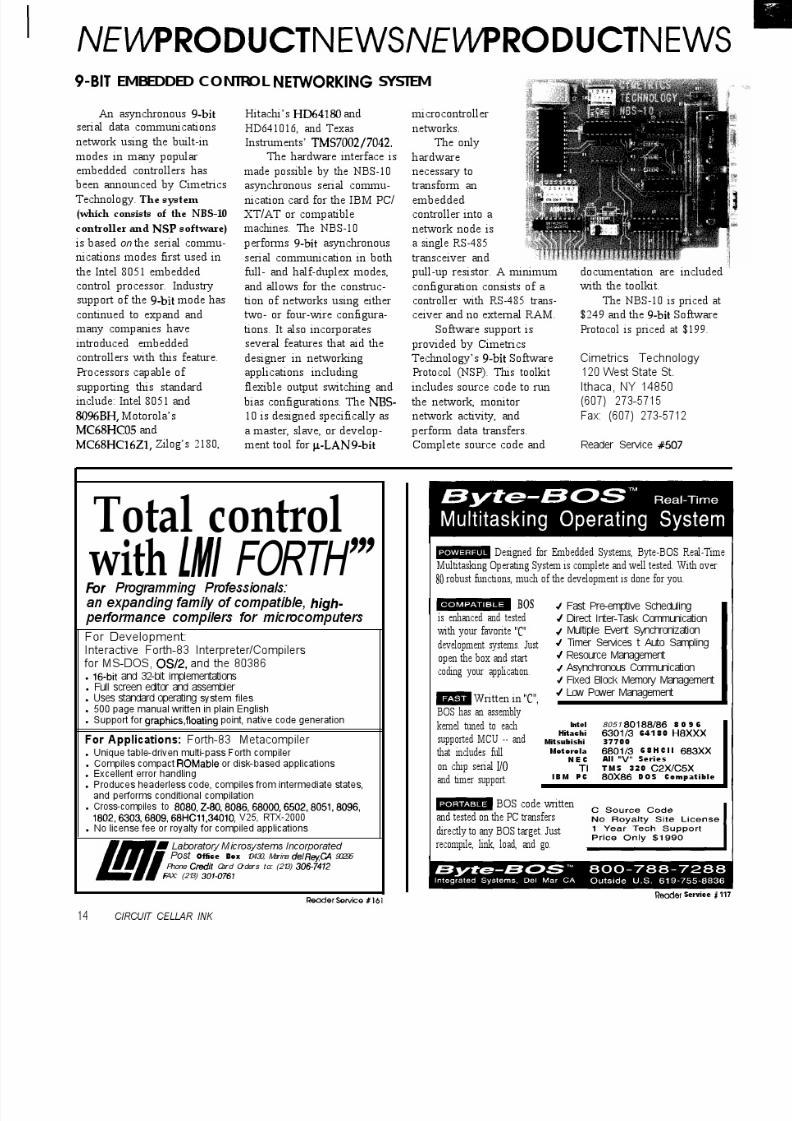
NElAPRODUCTNEWSNEl/VPRODUCTNEWS
COLOR CRTCONTROLLER ONSTD BUS
A color graphics CRT
controller, based on Hitachi’s
HD63484 ACRTC (AdvancedCRT Controller) graphics
processor, has been an-
nounced by Cubit. Using
high-level commands, the
Model 7050 controller
offloads much of the graphics
handling load from the main
system CPU, leaving it free
for other tasks.
The 7050 supports up to
three screens with 640 x 480
resolution. It includes 4 Mbitsof video RAM and is compat-
ible with VGA, EGA, and
monochrome monitors.
Sixteen colors from a range of
40% may be selected, and 16
shades of gray can be
displayed on monochrome
monitors. Both digital and
analog monitors are sup-
ported through Brooktree’s
RAMDAC chip. The board is
not CPU
dependent and
can be usedwith either &bit
or 16-bit Intel
and Motorola
microproces-
sor-based CPU
boards that
meet the STD
bus specifica-
tion.
More than
20 graphic
drawing commands, includ-ing LINE, RECTANGLE,
POLYLINE, POLYGON,
CIRCLE, ELLIPSE, ARC,
ELLIPSE ARC, and PAINT
are made available by the
ACRTC. Memory manage-
ment for split screens,
zooming, and scrolling are
also supported.
Cubit provides a library
of software routines written
in both Borland Turbo C++ Cubitand assembly language, and 340 Pioneer Way
a complete set of alphanu- Mountain View, CA
merit characters. The board 94041-1577
does not need a DOS operat- (415) 962-8237
ing system since Cubit’s Fax: (415) 965-9355
library provides the neces-
sary code. Reader Sercive 501
The Model 7050 CRT
Controller sells for $490.00 in
single quantities.
MICROMINIATURE CCD CAMERA
A microminiature solid-state CCD video camera, featur- CCTV Corporation
ing a unique Microelectronic Shutter has been introduced by 315 Hudson St. l New York, NY 10013
CCTV Corporation. The “GBC” CCD300 system allows the (212) 989-4433 l Fax: (212) 463-9758
Sensor itself to compensate for all light changes, eliminating
the need and cost of the traditional autoiris lens. Unlike a tube- Reader Service 502
type camera, there is no lag, burn in, or image retention.
Measuring 2.38”H x 1.38”W x 4.38”L, the 0.75-pound
unit can utilize both “C”- and “CS”-type lenses. It
operates from low voltage (7 to 12 volts DC) and comes
standard with a 120-volt AC-to-low-voltage DC power
module. Full video can be achieved with light levels as
low as 2 lux (0.2 footcandles).
Resolution is in excess of 350 lines, both at the center
and corners. The CCD300 features adjustable gamma,
automatic black level, built-in image enhancer, mirror
image reversal, and switchable auto/manual gain. The
automatic gain control has a range of 1000 to 1 (four f-
stops electronically within the camera). The light compen-
sation is a minimum of 10,000 to 1 electronically and there
is no geometric distortion. No price was available at press
time.
10 ClRClJlT CELLAR INK

8/13/2019 Circuit.cellar.023.Oct Nov.1991
http://slidepdf.com/reader/full/circuitcellar023oct-nov1991 9/100
lA/PRODUCTNEVVSNEl/VPRODUCTNEWSNY CONTROLLER BOARD INCLUDES DESIGNOOL FEATURES
An 8051-based single-board controller for data collection, embed-
ed control, and product design applications has been announced by
lue Earth Research. The Micro-440 uses a 12-MHz Intel 83C51FB,
hich includes advanced features such as high-speed I/O, three 16-bitmer/counters, multiprocessor communications, a Boolean processor,
nd a watchdog timer. Measuring 1.89” by 2.25”, the 6-layer board is
manufactured using double-sided surface-mount technology.
Time- and date-based operations are managed by the real-time
ock/calendar module. The module features a 12/24-hour format,
utomatic leap year setting, and interrupt output periods ranging from
second through 1 hour.
For measuring analog inputs, the on-board &bit ADC can convert
gnals ranging from 0 to 5 volts in less than 40 microseconds. The eight
put channels can be programmed for single-ended or differential
peration.
Available I/O includes 14 TTL/CMOS-compatible I/O lines, dualS-232C serial ports with activity LEDs, and a low-power shutdown
ature. CPU bus connections are also available for adding memory or
her peripherals.
The Micro-440 can be powered from any 6- to 16-volt DC source
apable of 75 mA (7 mA in standby). The on-board regulator provides a
able +5 volts (fl ) to internal circuitry and includes a CPU reset
ature. An optional 3.6-volt lithium battery maintains RAM data and clock operation for more than 10 years.
Available evaluation units include the controller board, back-up battery, and two 25-pin D-shell connectors, assembled and
stalled in a protective plastic housing. A complete system design package includes the Evaluation Unit; Macro Assembler,
ymbolic Debugger, and Utility programs; comprehensive manuals (llOO+ pages), plug-in type DC power supply, applications
evelopment module; and serial interface cable. Also available are Intel’s PL/MSl compiler and Franklin Software’s C51
ompiler in value-priced packages that include the Micro-440 evaluation unit and accessories.The Micro-440 sells for $99, in quantities of 1000. The Evaluation Unit sells for $199, and the System Design Package is $379.
lue Earth Research10 Belle Ave. l Mankato, MN 56001 l (507) 387-4001 l Fax: 507) 387-4008 Reader Service 5@3
HIGH-RESOLUTIONMAGE CAPTUREBOARD
Supervision/l6, a video
mage capture system for theBM PC/AT family of
omputers, is available from
DEC Inc. The Supervision/
6 package consists of the
DEC frame grabber and
oftware for image capture.
The software and
ardware is fully compatible
ith all IBM-style AT-type
machines and allows the user
capture video images from
ny standard RS-170 videoource, such as a camera,
video tape, or live broadcast.
The image is captured with a
resolution of 512 pixels by
488 lines with 256 shades of
gray. The resulting picture
can be displayed on any VGAmonitor in the 320 x 200 x 256
mode. The picture displays as
256 x 200 with 64 shades of
gray.Many super VGAs are
supported to allow viewing
of the images in 640 x 480 x
256 mode with the image
displayed as 512 x 480 with
64 shades of gray. The image
can be adjusted for contrast
and brightness, stored to andretrieved from disk, and
printed on a laser printer.
With the super VGA
display, the 256~gray-level
picture rivals black-and-
white TV broadcast quality,
as the eye can detect nodigital artifacts at this level.
The choice of display has no
bearing on the print quality
since the printed image is
printed directly from the disk
file image, not from the
screen as with most screen
capture utilities.
The image is captured in
l/30 second and is stored in
TIFF or PCX format for direct
use by many desktop publishing packages. Pictures
are easily included in such
packages without the expense
and limitations of a desktop
or hand-held scanner.
The Supervision/l6
package includes interfacecard, software on disk,
owner’s manual, and one-
year warranty. The Supervi-
sion/16 costs $369.95 in
single quantity.
IDEC, Inc.
1195Doylestown PikeQuakertown, PA 18951
(2 15) 538-2600
Fax: (2 15) 538-2665
Reader Service 5 l
October/November 199 1 11

8/13/2019 Circuit.cellar.023.Oct Nov.1991
http://slidepdf.com/reader/full/circuitcellar023oct-nov1991 10/100
lVEVVPRODUCTNEWSNEVVPRODUCTNEWS
graphic adapters are s
recommended.
The EDC-10OOHR
sor configured into
HIGH-RESOLUTION ELECTRONIC IMAGER
Electrim Corporation has announced the availability of a
high-resolution version of their EDC-1000 solid-state electronicimager. The EDC-1000HR gives the user the ability to directly
digitize images at up to 754 x 488 pixels. The EDC-1000HR is a
compact, digitally controlled, digital output television-like
monochrome camera.
The EDC-10OOHR is fully compatible with an IBM PC XT/
AT or equivalent and does not require a frame grabber or
other third-party hardware or software. All popular IBM PC
upported, but VGA or super VGA is
uses a fra(me-transfer CCD image
244 lines with 754 elements in each line.
The imager can be operated in either interlaced or
noninterlaced mode. Features include: computer-controlled
exposure time, frame scanning time, and subarray scanning;asynchronous scanning (external triggering of frame reset and
scan); and pixel data collection rates of one megapixel/second
(3 to 5 frames per second in live mode). Output from the
imager is an 8-bit digital signal corresponding to the quantized
value of brightness at serially sampled spatial data points.
TIFF and PCX file images can be saved for use by image
processing and desktop publishing packages.
The EDC-10OOHR digital, asynchronous camera and
computer interface card operate entirely under the control of
the PC, collecting image data via the PC bus in parallel. Upon
a command from the PC, image exposure takes place and 256
gray level image data is read directly into the computer’sRAM.
The EIX-1OOOHR sells for $850.
Electrim Corporation
P.O. Box 2074 l Princeton, NJ 08543
(609) 683-5546 l Fax: (609) 683-5882
Reader Service 505
PC-Based Logic Analyzers
Sophisticated Logic Analysisa’, Unsophisticated Prices
ID160 (50 MHz) for $695*ID161 (100 MHz) for $895
*SO MHz or 100 MHz Sampling l 8K Trace Buffer l 32-channelOperation *Multi-Level Triggering *State Pass Counting*Event Timer/Counter *Performance Histograms *HardcopyFutput *Disassembles popular bit micros *and much more
30 Day Money Back Guarantee
INNOTEC DESIGN, INC.6910 Oslo Circle, Suite 207Buena Park, CA 90621Tel: 714-522-1469 FAX:714-527-1812
8031 CONTROLLER BOARDS
A&T: $129 Partial kit: $70 PCB Board kit: $25
l 11.0592 MHz clockl 8/16 K EPROM socketl 8132 K RAM socketl MAX232 serial I/O
l Two 20-pin expansionheaders
l Monitor, application notes& support softwareincluded
9 Accessories availableEMC32 Board (3” x 4”)
A&T: $80 Full kit: $62 Partial kit: $36
L.S. ELECTRONIC SYSTEMS DESIGN2280 Camilla Rd., Mississauga, Ont. L5A 2J8 Canada
Phone/Fax: (416) 277-4893Terms: Shipping USICanada $6. Check or Money Order please.
12 CIRCUIT CELLAR INK

8/13/2019 Circuit.cellar.023.Oct Nov.1991
http://slidepdf.com/reader/full/circuitcellar023oct-nov1991 11/100
8/13/2019 Circuit.cellar.023.Oct Nov.1991
http://slidepdf.com/reader/full/circuitcellar023oct-nov1991 12/100
8/13/2019 Circuit.cellar.023.Oct Nov.1991
http://slidepdf.com/reader/full/circuitcellar023oct-nov1991 13/100
NTERACTIVE SCHEMATIC CAPTURE ANDDIGITAL SIMULATION SOFTWARE
DesignWorks, from Capilano Computing Systems Ltd.,
ombines the power of Apple Macintosh graphics with a
riendly user interface to simplify schematic entry and
imulation. DesignWorks can write net list, simulation, andraphics files in a variety of standard and user-definable
ormats to facilitate transfer to other systems. The integrated
chematic entry and digital simulation allows detection of
esign errors before they are wired into hardware.
DesignWorks makes full use of the Macintosh
multiwindow environment, allowing any number of circuit
les open simultaneously and full Cut/Copy/Paste editing
perations between circuits. Multipage schematics are fully
upported with page connectors and interactive simulation
cross pages. Device and signal dragging with fully interactive
nd orthogonal rubberbanding reduce editing time.
Pull-down menus and an on-screen tool palette provideuick access to all program functions. Modeless operation
rovides immediate access to any program function at any
me without moving through hierarchical menus.
Control devices such as switches are active right on the
iagram, and can be changed in state to observe their effect on
he simulation in progress. Probes and numeric displays can
lso be placed directly on the schematic to observe signal
alue changes. Any selected signals can be displayed in the
orm of a logic-analyzer-style timing diagram. The diagram is
pdated continuously to reflect design and parameter
hanges.
DesignWorks has complete symbol drawing and librarymaintenance capability, allowing the rapid creation of new
evices. The “AutoSym” feature will generate a standard
ectangular symbol given only a list of input and output pins.
or simulation purposes, any circuit can be associated with a
ymbol to allow the creation of fully functional custom
evices. Libraries of these custom devices can be maintained
o suit project requirements.
The DesignWorks Report module allows full
ustomization of text report formats, eliminating tedious file
ranslation or manual modifications. Report formats include
et lists by signal or device, bills of materials, signal lists with
imulation event data, and signal and device lists withraphical data.
DesignWorks is compatible with any Macintosh with two
megabytes or more of memory. The absolute maximum circuit
ize is 32,767 devices, although drawing and simulation speed
mits circuits to 500 to 5000 devices depending on computer
model. DesignWorks sells for $995.00.
Capilano Computing Systems ltd.
1168 Hamilton St., Suite 501
Vancouver, B.C. l Canada V6B 2S2604) 669-6343 l Fax: 604) 669-9531
Reader Service 508
*TEXT EDITOR, CROSS ASSEMBLER, ANDCOMMUNICATIONS FACILITY IN A COMPLETEINTEGRATED DEVELOPMENT ENVIRONMENT
l MACROSl CONDITIONAL ASSYl LOCAUAUTO LABELS* SYMBOL TABLE CROSS REF
us g4;.95
l S OR HEX FILE OUTPUT DOWNLOADS pLus S’H*TO MOST EPROM PROGRAMMERS
AVAILABLE FOR MOST 8-BIT MICROPROCES-SORS AND 680001010. CALL OR WRITE FOR
TECHNICAL BULLETIN. 30 DAY MONEY BACKGUARANTEE. MCIVIAE.
* PER SHIPMENT:$5 CONTIGUOUS USA$10 CANADA AK, HI$20 INTERNATIONAL
Micro Dialects, Inc.DEPT. C, PO BOX 30014CINCINNATI, OH 45230
(513) 271-9100
d er sewice 73
see us al The Embedded sysfm cmfenmce Boolh x
Octob er/November 199 1 15

8/13/2019 Circuit.cellar.023.Oct Nov.1991
http://slidepdf.com/reader/full/circuitcellar023oct-nov1991 14/100
8/13/2019 Circuit.cellar.023.Oct Nov.1991
http://slidepdf.com/reader/full/circuitcellar023oct-nov1991 15/100
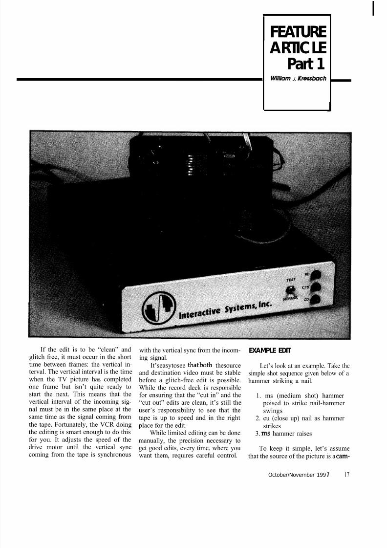
FEATUREARTICLE
Part 1, Wl lbm J. Kressbach
If the edit is to be “clean” andglitch free, it must occur in the shorttime between frames: the vertical in-terval. The vertical interval is the timewhen the TV picture has completedone frame but isn’t quite ready tostart the next. This means that thevertical interval of the incoming sig-nal must be in the same place at thesame time as the signal coming fromthe tape. Fortunately, the VCR doingthe editing is smart enough to do thisfor you. It adjusts the speed of thedrive motor until the vertical synccoming from the tape is synchronous
with the vertical sync from the incom-ing signal.
It’seasytosee thatboth thesourceand destination video must be stable
before a glitch-free edit is possible.While the record deck is responsiblefor ensuring that the “cut in” and the“cut out” edits are clean, it’s still theuser’s responsibility to see that thetape is up to speed and in the right
place for the edit.While limited editing can be done
manually, the precision necessary to
get good edits, every time, where youwant them, requires careful control.
EXAMPLE EDIT
Let’s look at an example. Take thesimple shot sequence given below of ahammer striking a nail.
1. ms (medium shot) hammer poised to strike nail-hammer swings
2. cu (close up) nail as hammer strikes
3. ms hammer raises
To keep it simple, let’s assumethat the source of the picture is a cam-
October/November 199 1 17
8/13/2019 Circuit.cellar.023.Oct Nov.1991
http://slidepdf.com/reader/full/circuitcellar023oct-nov1991 16/100
8/13/2019 Circuit.cellar.023.Oct Nov.1991
http://slidepdf.com/reader/full/circuitcellar023oct-nov1991 17/100
I I I I I I I I I I I I
I IThe “To Tape” and‘“From Tape” signalsneedaddifionalcondi-Coning between themntrollerandthetape
decks. Since suchcwditioning dependson the tape deck be-ing used. it is impos-
sble lo present a cir-cuit here that would
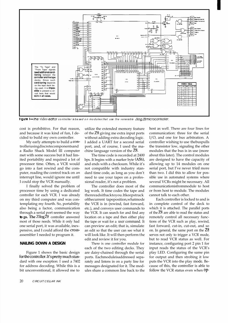
Figure 1 Ihe video e d t o r co n t ro l le r is ba sed o n mo du les t ha t u se t h e v e ne ra b le Wa g ZB m / c ro c o n t r o lle r .
cost is prohibitive. For that reason,and because it was kind of fun, I de-cided to build my own controller.
My early attempts to build a con-trollerusingdiscretecomponentsanda Radio Shack Model III computermet with some success but it had lim-
ited portability and required a lot ofprocessor time. Often, a VCR wouldgo into a fast rewind and the com-puter, reading the control track on aninterrupt line, would ignore me untilI could stop the VCR manually.
I finally solved the problem ofprocessor time by using a dedicatedcontroller for each VCR. I was alreadyon my third computer and was con-templating my fourth. So, portabilityalso being a factor, communication
through a serial port seemed the wayto go. The ZilogZS controller answeredmost of those needs. While it only hadone serial port, it was available, inex-pensive, and I could afford the cross-assembler I needed to program it.
NAILING DOWN A DESIGN
Figure 1 shows the basic designforthecontroller.It’sprettymuchstan-dard with one exception: I used a 7402
for address decoding. While this is abit unconventional, it allowed me to
20 C IRCUIT CELLAR INK
utilize the extended memory featureof the 28 giving me extra input portswithout adding extra decoding logic.I added a UART for a second serialport, and, of course, I used the ma-chine language version of the 28.
The time code is recorded at 2400
bps. It begins with a marker byte (A5h1,and ends with a checksum. While it’snot compatible with industry stan-dard time code, as long as you don’tneed to use your tapes on a profes-sional reader, it’s not a problem.
The controller does most of theleg work. It time codes the tape andthenreadsitbacktoyou.Itkeepstrackofthecurrent tapeposition,whatmodethe VCR is in (rewind, fast forward,etc.), and conveys user commands to
the VCR. It can search for and find anylocation on a tape and then either playthe tape or wait for a user command. Itcan preview an edit; that is, simulatean edit so that the user can see what itwill look like. It will then perform theedit and review it for you.
There is one controller module foreach of the two editing decks. Theyare daisy-chained through the serialports. Eachmoduleisaddressed sepa-rately and listens in on a party line for
messages designated for it. The mod-ules share a common line back to the
host as well. There are four lines forcommunication: three for the serialI/O, and one for bus arbitration. Acontroller wishing to use thebuspullsthe transistor low, signaling the othermodules that the bus is in use (moreabout this later). The control modules
are designed to have the capacity ofallowing up to 14 modules on oneserial port, but I’ve never tried morethan two. I did this to allow for pos-sible use in automated systems whereseveral VCRs might be necessary. Allcommunicationisfrommodule to hostor from host to module. The modulescannot talk to each other.
Each controller is locked to and isin complete control of the deck towhich it is attached. The parallel ports
of the 28 are able to read the status andremotely control all necessary func-tions of the VCR such as play, rewind,fast forward, cut-in, cut-out, and soon. In general, the same port on the Z8
serves not only to trigger a VCR mode,but to read VCR status as well. Forinstance, configuring port 2 pin 1 forinput reads the status of the VCR’splay LED. Configuring the same pinfor output and then strobing it lowputs the VCR into the play mode. Be-
cause of this, the controller is able tofollow the VCR status even when op-
8/13/2019 Circuit.cellar.023.Oct Nov.1991
http://slidepdf.com/reader/full/circuitcellar023oct-nov1991 18/100
8/13/2019 Circuit.cellar.023.Oct Nov.1991
http://slidepdf.com/reader/full/circuitcellar023oct-nov1991 19/100

8/13/2019 Circuit.cellar.023.Oct Nov.1991
http://slidepdf.com/reader/full/circuitcellar023oct-nov1991 20/100

8/13/2019 Circuit.cellar.023.Oct Nov.1991
http://slidepdf.com/reader/full/circuitcellar023oct-nov1991 21/100
The Equipment
The VCRs used in this article are Sony 2860As. I have question, and play it. The time readout should count
also used Sony 2850s and tested Sony 5850s with good while the recorded part of the tape is playing, and then
results. VCRs from other manufacturers should work as should stop when the blank part of the tape isencoun-
long as they are designed to work in an editing system tered. Fast-forward the tape a little. The counter should
and are equipped with a parallel port, You should be not move. Now, rewind the tape. The counter should
aware there is no c ompatibility between manufac turers remain unchanged until it encounters the part of the
and you’ll have to check the manuals carefully for pin tape that has been recorded. Again put the tape in
assignments and voltage requirements before attempt- fast-forward, The counter should count until it reaches
ing any interface. Many of the newer VCRs use serial the blank part of the tape, and then stop counting. A
interfaces and may have quite different requirements, machine that reacts in this manner indicates that it is
Many of you may want to try using VHS, S-VHS, 8mm. probably reading from the control track. This makes it a
or other small format VCRs. The c rucial fac tor in a suc- good candidate for computer control. A blank tape
cessful editing interface is the ability to access the control has no control track, so if the readout continues to
track pulses. The pulses must be available not only during count while blank tape is passing over the heads, then
playback, but also while the tape is in fast forward and you can assume that the counter is reading something
rewind. The key to recognizing a suitable VC R is to first other than the control track and the machine is prob-
check to see if it uses a footage counter or a tape time ably unsuitable for conversion.
readout. In the past most consumer VCRs used mechani- Be careful! Each VC R has its own little quirks. For
Cal footage counters for displaying elapsed tape time. instance.1 haveaVCRthatwill notgointorecordmode
This method is much too inaccurate for editing purposes, from play mode; it has to be in pause first. Be sure that
But I have noticed lately that most of the higher end you thoroughly understand the operating characteris-
consumer VC R and nearly all industrial VCRs now display tics of a VCR to be certain itwili fit into an editing system.
tape time in minutesand seconds. They seem to maintain Easy remote control of VCRs with infrared remotes
good accuracy in both rewind and fast forward and it could be achieved through the use of an infrared
seems likely that the control track is being used for tape controller similar to the one described by Steve in
time display. If the manufacturer is using the control track volume 6 of his “Ciarcia’s Circuit Cellar” books.
to display elapsed time, it seems likely that the resource- There are also companies that make computer
ful engineer should be able to find a way to use it as well. interface devices for infrared VCRs. You send them your There is a way to determine if a machine is using the VCR and the c ompany returns it to you with an inter-
control track. First get yourself a blank tape. It must be a face attached directly to the VC Rs infrared sensor. The
tape that has never been recorded on. Record about interface is preprogrammed. ready to plug in to your
thirty seconds of video on it, load it into the machine in computer.
and the cut-out locations. This makesit look like an edit was preformedwithout actually doing it.
If a review has been called for, thecontroller just lets the tape play.
Finally, after a short postroll to letthe viewer see how well the edit fit,the controller stops the machine andthen transmits the exact edit locations
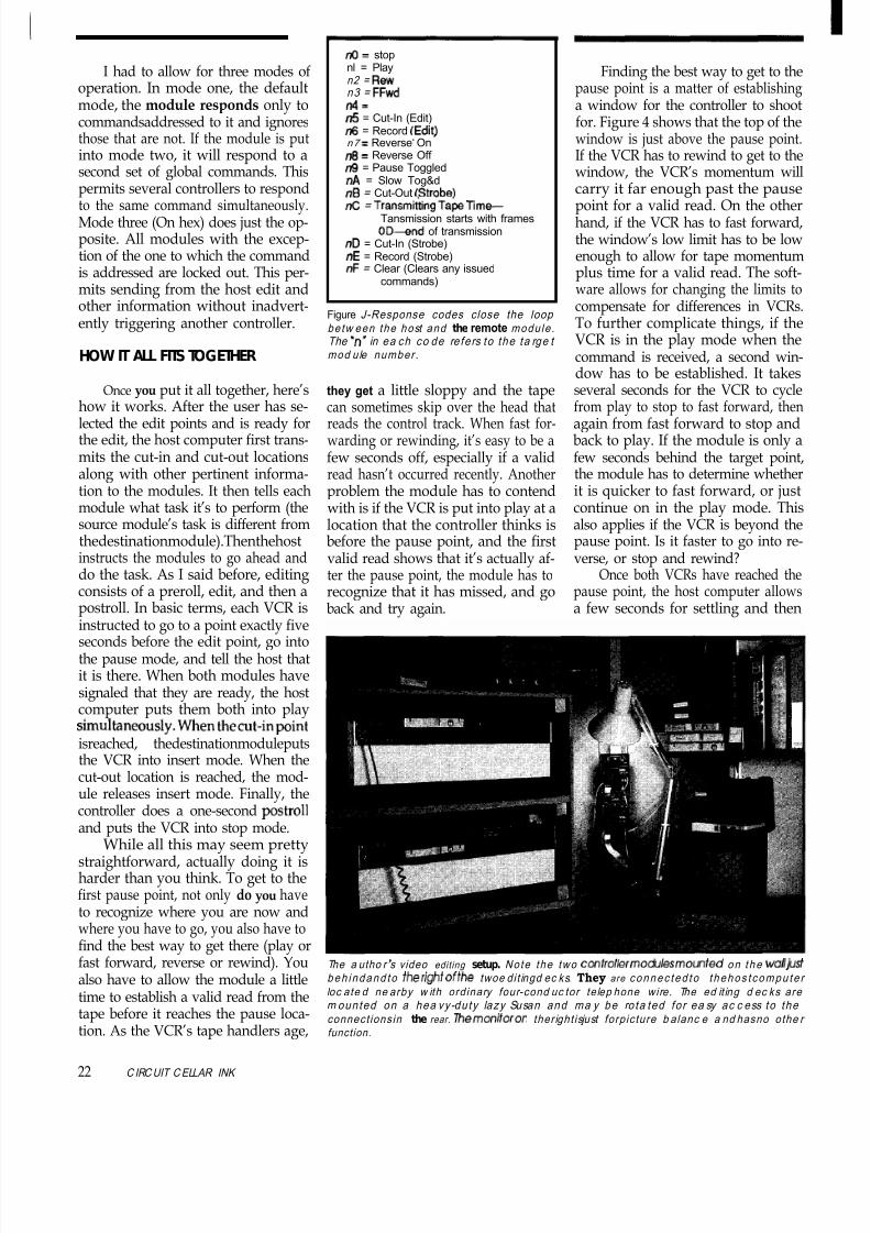
to the host computer.The preroll time, postroll time,and the bottom of the search windoware all user selectable. I should saythat the preroll time changes to fitcertain requirements and VCRs. Thepreroll time for an edit is five seconds.This allows plenty of time for stablepictures before the edit. That is notquite so important for a preview, andso to save time, the preroll for a pre-view is only two seconds.
There are three different editingpatterns that can be selected. Code
Thehost compute randmon i to ra reconnec ted to theed i t ingdecks loca tednearby . Wh i le m an y op erato rs prefe r to use tw o m onitors. I no rma lly use just o ne. Vid eo is sw itche d be tween the two VCR source s au tom at ica l ly . The ed it ing stat ion is loc ate d on a deskwhich is backed b y a b ui lt - in 130-gallon sa lt w a fer aq ua rium . This helps to m a ke the som etim es stressful task of vide o e d it ing a bit m ore relaxing.
24 ClRCUT C ELLAR INK

8/13/2019 Circuit.cellar.023.Oct Nov.1991
http://slidepdf.com/reader/full/circuitcellar023oct-nov1991 22/100
3Ah selects the “find, play, pause, edit,and postroll” sequence just described.A second similar pattern, 3Bh, adds aslow mode just before the pause. Thisis the one I use most since it pauses thetape a little more accurately. Finally,3Ch has no pause at all. No need topause if the source is a camera.
You can also have the modulefind any location on the tape. Oneversion of this (39h) searches and goes
Figure 4-Finding t he be st wa y to ge t to the
pa use p oint is to e stab l ish a w indo w fo r the
to shoot fo r.
into the play mode when the requestedlocation is found. The other (38h) juststops without going into play. This isin case you’re looking for somethingat the other end of a long tape andwant to refill your Coke while it’s
getting there.Until I started getting this article
ready, I had no idea that the controllerhad become so complex. I developedit over the course of the nine years thatI’ve been free-lancing. I would usu-ally tinker with it when I had work todo but didn’t feel like doing it. Thatmust have happened a lot over theyears.
That covers the construction andsoftware for the control modules. In
part two, I’ll look at software for thehost computer and discuss some op-tions that help simplify the entry andretrieval of editing information. +
Bill Kressbach holds a Master’s degree in In-structional Media and Technology from TheUniversity of Toledo. When he’s not shootingvideos, he does some computer programmingand is chief engineerfora college radio station.
IRS401 Very Useful
402 Moderately Useful403 Not Useful
PARqDlGMThe Model for Programming Productivity
3301 Country Club Road, Suite 2214 l Endwell, NY 13760 l (607) 746-5966 l
Oc tober /November 199 7

8/13/2019 Circuit.cellar.023.Oct Nov.1991
http://slidepdf.com/reader/full/circuitcellar023oct-nov1991 23/100
FEATUREARTICLEChris ciarcia
Computer Graphicsand the World of Scientific Visualization
As a result of the advance-ments in data generation and com-puter technology over the last fewdecades, methods of managing andanalyzing large volumes of complexdata have been largely responsible for
a strong interest in scientific visual-ization as a new computational tech-nology. This visualization technologyhas its origins within the realms ofapplied science and engineering wheretheuseofcomputerdisplaytechniquesin computer-aided design and engi-neering analysis have provided aninitial driving force for the develop-ment of “computer graphics technolo-gies”duringtheearly 1970sand 1980s.Since then the problem of interpret-
ing, understanding, and processinglarge complex data sets has grownconsiderably. This need has created astrong desire for effective “realistic”graphics tools which have in turnforced these original display tech-niques to expand and grow within avariety of computational environ-ments. As such, a whole new set of“visualization” methods has evolvedbased on the use of computer simula-tions and computer graphics.
Originally, entertainment appli-cations fueled the fires of computergraphics in the middle 1980s whilebasic engineering applica tions becamestandardized and moved out of theresearch context into routine practice.And, the simultaneous developmentof PC technology designed to supportadvanced graphics display capabili-ties served as a foundation and princi-pal support to this evolutionarygrowth process. As a result, the basic
visual vocabulary of computer graph-ics became extended in both breadth
and depth. Graphics applications be-came more adept at meeting the re-quirements of applications needingrealism, visual richness, and motion(animation). Scientific visualizationwas born. Now it seems to be the new
“catch word” and it has become amajor focus of computer graphics inthe 1990s.
Problem Definition
VisualizationEnvironment
ScientificVisualization
Rendering
Figure -The scientific visualization process.
But this emphasis on visualiza-tion technology is an obvious step forthe computational world. As numeri-cal simulation continues to become amoreaccepted (and cost effective) toolfor basic scientific research, the need
of the scientist to understand and “vi-sualize” the complex nature of theirnumerical simulations only increases.Fortunately this process has been en-riched by advances within the enter-tainment world. But regardless of thesource of advancement, computergraphics technology has grown to be-come an essential component of thisnew field of “computational science.”As a result, the current rapid develop-ment in visualization technology
within the sciences and engineeringhas been only impeded by the growthin the power and sophistication ofcomputergraphicshardwareandsoft-ware systems.
In general, “visualization” can bedefined as the use of computer graph-ics imaging technology as a tool forcomprehending data obtained bysimulation, computation, or physicalmeasurement. As such, it is built onthe integration of techniques
“snatched” from older technologiesincluding computer graphics, imageprocessing, computer vision, com-puter-aided design, geometric mod-eling, approximation theory, percep-tual psychology, and user interfacestudies. But the most fundamentaldefinition of the visualization tech-nique lies not in its components butrather in its intent. It is important toremember that the purpose of scien-tific visualization is to gain “insight”
into the behavior of some complexprocess under scrutiny. Individual
26 ClRC LJlT C ELLAR INK

8/13/2019 Circuit.cellar.023.Oct Nov.1991
http://slidepdf.com/reader/full/circuitcellar023oct-nov1991 24/100
numbers (or single components of aarge database) are not important. In-tead, its effectiveness lies in its abilityo rapidly communicate large amounts
of information in a format that en-hances comprehension and insight.
Historically the concept of visual-zation predates the computer era. If
you think about it, visualization hasbeen a part of the scientific methodever since the Greeks. They employedbasic linear graphing techniques inheir complex architectural designs.
But now we seem to want to handlemore than one-dimensional data, andhis new “complexity” requires that
we be more creative in our renderingechnique.
Therefore, in order to explore thesevisualization concepts on a practical
evel, I’ve decided to center this articleabout a detailed description of how tostructure and implement a basic “vi-sualization process” like thatflowcharted in Figure 1. I propose thatwe develop a computational “visual-aid” that will utilizenumericallysimu-ated data from the application of
Newtonian mechanics to the motionof an object within a gravitational fieldn order to demonstrate how basicnsight into a system’s behavior can be
gained from this visualization pro-cess. In doing this, we will be calledupon to apply basic tools from nu-merical analysis, computer graphics,and animation.
THE VISUALIZATION PROCESS
The best example is one that canbe easily recognized and compared toone within our own personal experi-ence. I have therefore chosen to “visu-
alize” a system based on the motion of a ball, falling off a wall and bouncingnto a hole. It’s a simple system that
each of us can visualize from experi-ence. As such, it will be easy to “see” if our numerical modeling and visual-zation look and act like the real thing.
But don’t be fooled. A simpleexampledoesn’t guarantee a simple computer model. A true representation of thisprocess requires that we numericallysolve a secondorder differential equa-
ion, create a visual environment, andanimate a time-evolving process.
We will construct this “scientificvisualization” along the guidelinesshown in the flowchart in Figure 1,where
1. Problem Definition-The basic problem is defined and the nature of the physical system to be visualized isdetailed. This process includes the
definition of the type of process under study, the limits on its behavior andits environment, and the underlyingscientific principles involved.
2. Modeling ~mafhemafica&--Thesystem model is chosen. Since thisexample will involve the application
and the configuration of the displayvehicle.
4. Creating the Visualization Envi-ronmenf-The background and eachcomponent of the visual display isdefined in detail and constructed for use within the “active” visual mode.This step involves the actual coding of
each component and the setup of anyanimation requirements.5. Rendering-Each component of
the “scientific visualization” applica-tion is combined to create an inte-grated environment. As the procedureisrun,themathematicalmodelisused
Ball
AY
Ground
Figure 2-The example used in the a rtic le is a simple ball which falls off a w a l l bounc es, and
usua lly fa lls into a ho le ne a r the righ t side of th e system .
of physical laws of motion, the math-ematical technique to be used must bedefined and applied in order to deriveappropriate equations of motion.These need to be consistent with a
form that is easily used within thecomputer graphics display environ-ment.
3. Visualization Mapping-The na-ture and extent of the actual “visual”display is defined, that is: What is theviewing field? How many objects willit contain? What form of backgroundis necessary? What video mode andresolution is necessary? Do you use black and white or color? Is the sceneanimated? In other words, this step in
the visualization process requires thedefinition of all the basic components
to predict the behavior of the systemin a step-by-step manner. The visualdisplay is then upgraded in a continu-ous fashion to reflect the changes inthe mathematically derived data.
Of course the specific procedureshown above is not “universal” to allscientific visualization processes. Thesource of our data could have beenempirical or from a closed-form ana-lytic solution instead of our chosennumerically simulated data. And thenature of the problem itself will obvi-ously change with application. How-ever, the techniques and conceptsemployed are generic across the spec-trum of physical science and can be
readily applied to many differentfields.
October/November 199 1 27

8/13/2019 Circuit.cellar.023.Oct Nov.1991
http://slidepdf.com/reader/full/circuitcellar023oct-nov1991 25/100
Our goal within this article is to gothrough the flowchart in Figure 1 in astep-by-step fashion while flushingout each component in order to createa practical, working scientific visual-ization example. But since this or anyother example is highly dependent onthe programming language, graphics
library, and display deviceused, I havechosen to develop our example in as“generic” a fashion as
possible. For a program-ming language I havechosen FORTRAN. Thisis n o t b e c a u s e Cwouldn’t be better. It’s
because I find FOR-TRAN easier for peopleto read. They can usu-ally follow the program
flow better without be-coming programmingexperts. Most of the timeI use C, but this is only
because I get better ac-cess to system-level func-tions for enhancing mydisplays. However, inthis application that isnot necessary.
PROBLEM DEFINITION
The first step in the example is thedefinition of the exact nature of the
problem we are going to solve. Wewill consider the motion of a bounc-ing ball that first rolls along the top of a wall and then falls off and bounces
several times until it falls into a hole inthe ground. A drawing of the appro-
yn +k 9
we will neglect air drag effects in this problem. But because the ball impactswith the ground and loses some en-ergy through that interaction and inthe elastic deformation process of the
ball’s surface, it is known that thevertical velocity is not conserved after each bounce. We can make a good
approximation to our own observedreal-world action by assuming that
approximately 28% of the total kinetic energyis lost during the ball-ground interaction. Thisis reflected in a verticalvelocity damping of about 15%aftereachcol-lision with the ground.Theverticalvelocity(Vv1of the ball after each
bounce is therefore ap- proximately equal to thenegative value of 85% of the vertical velocity be-fore the bounce.
yn
For a graphics li- brary I have chosen to
use the Microsoft Graph-icsLibrary Routinescon-tained in the MicrosoftFORTRAN V5.0 distri-
bution. Microsoft seemsto a fairly universal stan-dard and available to
t n+d? l
Figure3-The Runge-Kutta procedure uses a w eighted average of slop e s,w i t h those in the c enter rec e iv ing tw ice as muc h w eigh t as those o n the
As a “study” vari-able in the system, wewill allow changes in theinput of the magnitudeof the constant horizon-tal velocity Vxo. For our
purposes here, this value
will range from 0.38 ft/set (when the ball bounces and then justrolls into the hole) toabout 4.7 ft/sec wherethe ball has sufficient ve-locity to be “dunked”
most programmers. It is not the mostideal graphics set, but it does containmost of the basic graphics utilitiesneeded for addressing and assigningvalues to individual pixels within the
display screen. Its most obvious fail-ing lies in its restriction to the stan-dard VGA modes. The best it canhandle with 256 colors is the 320 x 200display resolution. Of course you canimprove the resolution to 640 x 480 if you wish to be restricted to 16 colors,
but I usually find this unacceptable. Ilike maximum “realism” wherever
possible. If you are looking for a morecomprehensive graphics library todevelop your own visualization ap- plication under, I recommend the Ge-nus GX Graphics Toolkit.
priategeometryanditsassignedcoor-
dinate system is shown in Figure 2.The ball will start its motion at the
coordinates (Xo,Yo) = (-1.0, 0.8) androll horizontally at constant velocity
Vxo until it reaches the edge of thewall f-0.8,0.8). It will then fall off thewall and strike the ground 1.3 feet
below and bounce upward. Theground itself is defined to be 0.5 feet
below the coordinate axis (y = -0.5).Each time the ball strikes the ground itwill either bounce or, if it falls in theappropriate place, it will fall into theholeandbetrapped.Thisholeisplaced
1.25 feet from the base of the wall. It is0.3 feet deep and 0.10 feet wide.
The ball is assumed to move hori-zontally with a constant velocity since
into theholewithoutbouncing. Higher velocities will miss the hole entirely.Several choices of Vxo are possiblewithin this range which will cause the
ball to land in the hole after a series of
bounces. If the ball misses the hole, wewill continue the computation until itreaches a horizontal coordinate loca-tion of 0.85 feet (Xstp>. If it enters thehole, we will allow it to slide down-warduntilitfalls toacoordinatedepthof Ysfp = -0.8 feet.
Since we will be studying the“motion” of a “dynamic system,” wewill be solving for the coordinates of the ball in a point-to-point fashionduring the time of its motion (flight path) from the top of the wall until itstops. The best visual aid for this ex-

8/13/2019 Circuit.cellar.023.Oct Nov.1991
http://slidepdf.com/reader/full/circuitcellar023oct-nov1991 26/100
8/13/2019 Circuit.cellar.023.Oct Nov.1991
http://slidepdf.com/reader/full/circuitcellar023oct-nov1991 27/100

8/13/2019 Circuit.cellar.023.Oct Nov.1991
http://slidepdf.com/reader/full/circuitcellar023oct-nov1991 28/100
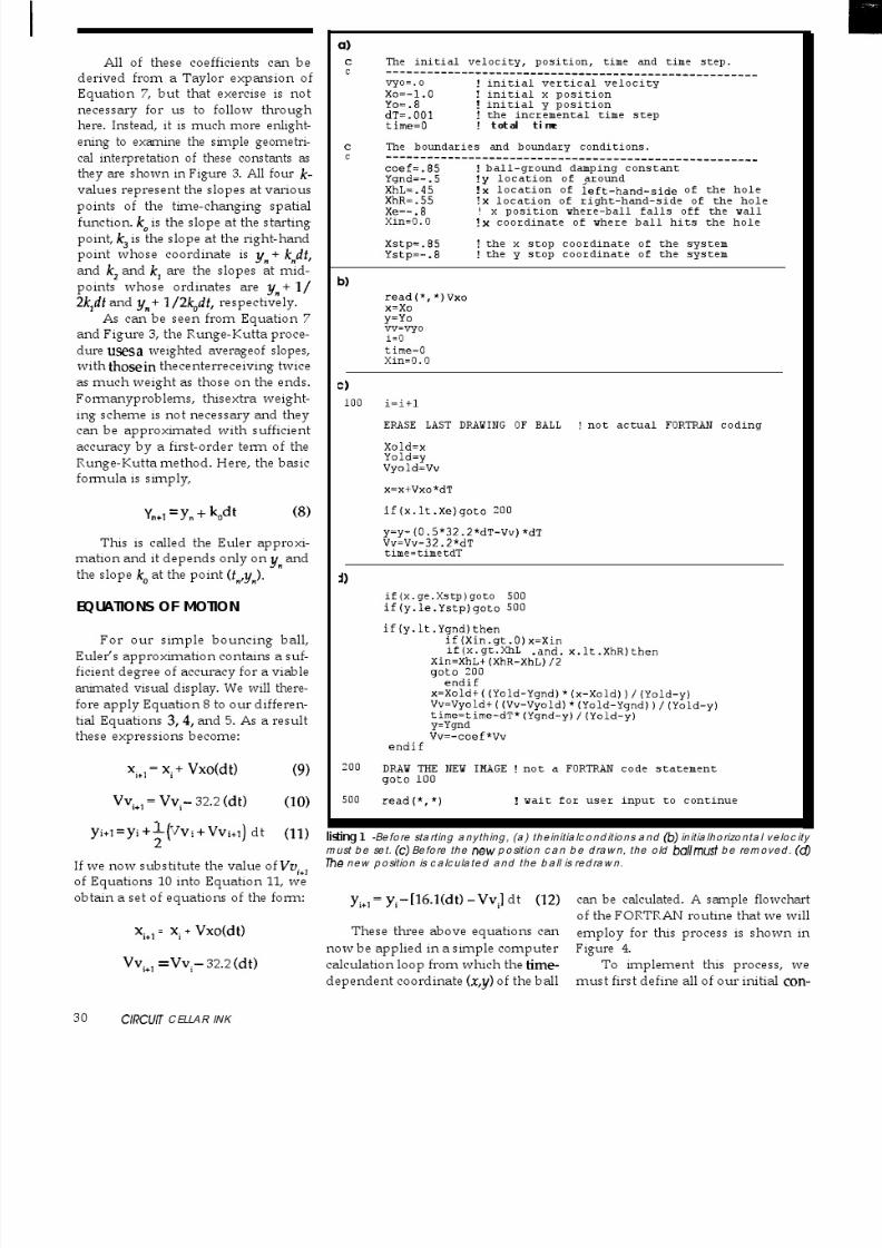
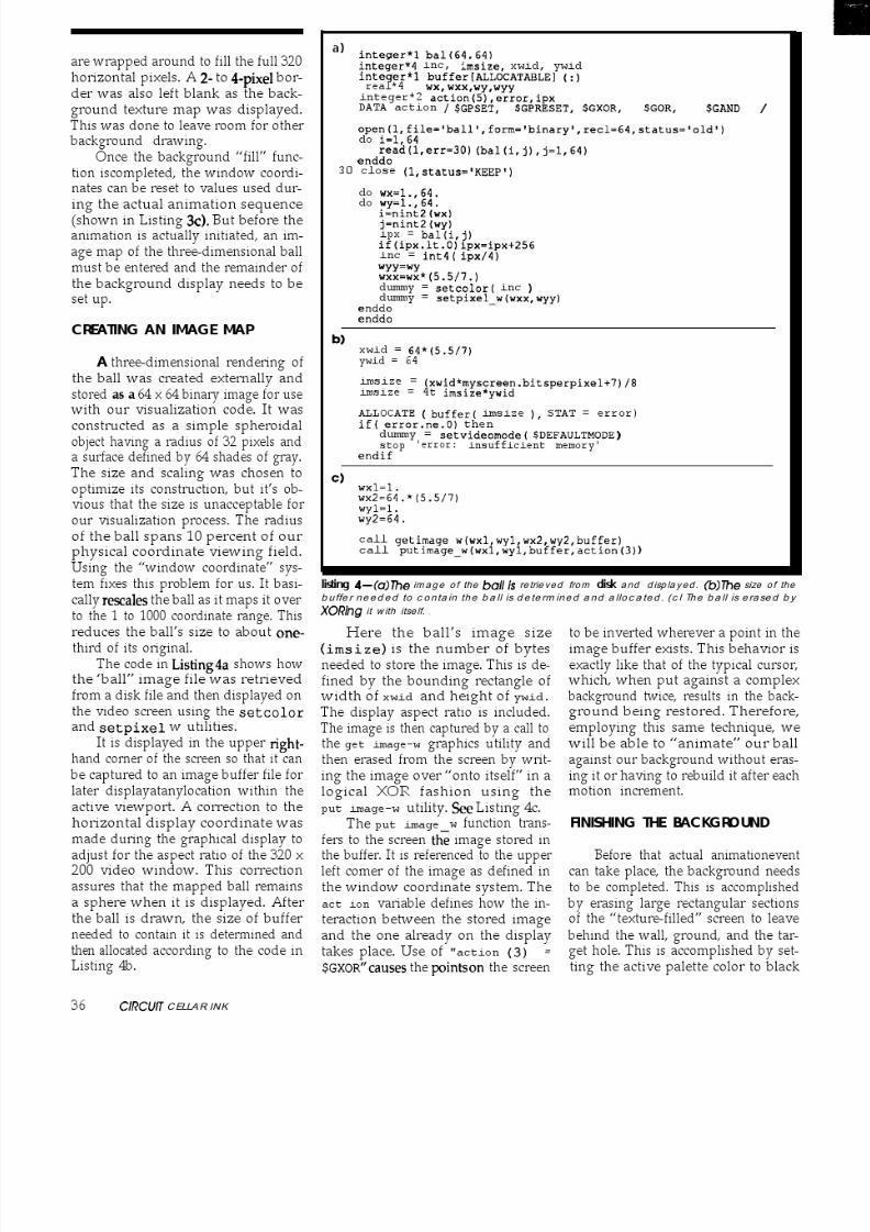
ditionsand decisioncoordinates. Sincea high degree of accuracy is not re-quired, each of these variables can bedefined as REAL*J in our example.The integer counter i is defined asINTEGER* 2 since we expect to exceed127 df time steps. See Listing la.
The initial horizontal velocity is
then input and the loop variables (x,y, Vv, i, time, Xin) are set to theirinitialconditions,showninListinglb.
below it (based on the distanced trav-eled in one time step dT), then wemust determine if it is falling into thehole or not. This is accomplished bytesting to see if the x-position is withinthe hole’s width between x = 0.45 to x= 0.55. If it is, then the position is resetto the center of the hole (xin) and the
ball is drawn at the new position andallowed to fall to the bottom in thenext few cycles.
The cycle counter is thenincremented by 1 and the basic loopprocedure is started. Since this is an“animation sequence,” the last draw-ing of the ball within the display im-age is erased so that the new imageposition can be drawn after its newposition is determined. However, be-fore this calculation takes place, the
current position and velocity corre-sponding to this last (ith) cycle isstored in temporary storage Xold,
Yo Id, Vvo Id) and the new x position(for cycle i+l is determined. If the ballcollides with the ground, these previ-ous (old) values will be used to deter-mine the ball’s reflection from thatsurface. If the ball is still on top of thewall, that is, for x less than xe, then theball is drawn at its new horizontalposition and the counter is incre-
mented for the next cycle. Otherwise,the i+l cycle y coordinate y , verticalvelocity WV), and the total elapsedtime is calculated. See Listing lc.
Thiscentercoordinatexinisusedfor multiple purposes. It centers andconstrains the motion of the ball as itslides down the hole so that we cansimulate the realistic motion of a solidspherical ball sliding down a circularpipe slightly larger than itsown diam-eter. But at the same time it is used asa trigger function. It indicates whether
or not the ball has entered the hole. IfXin = 0 then we know that the ball hasyet to reach the hole. If Xin is greaterthan zero then we know it has just hitthe hole or is sliding down it.
Once the new position of the ballis determined, it is necessary to makeseveral conditional tests to determinethe current status of the calculationsequence. The position is first testedto determine if the ball has reached itsend-point boundary conditions. Inother words, has it fallen into the hole
and reached itsbottom (Ystp = -0.80)or has it bounced past the hole to theright-hand side of the display screenand reached the x-stopping point(xs tp = 0.85)? If either of these condi-tions is met, the calculation and ani-mation sequence is suspended.
If the ball is not in the hole and they coordinate indicates that it has col-lided with the surface, then the ballmust bounce. Under these conditions,the new x-coordinate location andvertical velocity are calculated usingthe previously stored values from the
last cycle. The velocity is thendampedby 15% and its direction is inverted tosimulate the reflection of the ball offthe ground surface. The new positionof the ball is then displayed in theanimationsequenceand thenextcycleis initiated, as shown in Listing Id.
Once the total motion sequence iscompleted, a new horizontal velocitycan then be input and a new test of theball’smotioncanbe “visualized.“Howthis visualization is accomplished us-
ing the simple graphics utilities avail-able within the Microsoft GraphicsUtility Library is the subject of thenext few sections.
VlSUALlZATlON MAPPING
If the ball has not reached these The next step in creating a work-stopping boundaries, we must deter- able “visual” representation of ourmine if it should bounce or continue in scientific model is based on the defini-its upward or downward flight path. tionofthegraphicsenvironment.ThisThis is accomplished by testing the display must be chosen carefully since
value of the y coordinate. If the ball’s it is highly dependent on the nature oflocation is at the surface or slightly the process being visualized. For our
October/November 199 1 3 1

8/13/2019 Circuit.cellar.023.Oct Nov.1991
http://slidepdf.com/reader/full/circuitcellar023oct-nov1991 29/100
bouncing ball scenario, we need onlyconsider the animated motion of asingle object: the ball. But that ballmust move within some referencedenvironment. This environment, orbackground image, must be laid outto correspond to the system limits andboundary conditions specified in the
previous “modeling” section. Andsince this is an animated visualiza-tion, we must take into account thespecific hardware used. This greatlyaffects the time needed for imagemodifications. It’sobvious thatdiffer-ent graphics cards, screen memorymanagement, and processor clocksspeeds affect the rate at which a pixelon the screen can be changed. There-fore, before selecting the display mode,the following should be considered:
1. How much visual detail doeseach object or component of the back-ground require?
2. How many colors or shades ofgray are necessary to properly renderthat detail?
3. If you are animating objects,what constraints on the image refresh
Figure 5a A Iwo-d imens iona l textured ba ckground is used to ad d some rea lism to the
simu la t i on .
speed exist due to the size and num- 4. What constraints do you haveber of colors of each object (the num- placed on your choice of video modeber of bytes per pixel and the number resultingfromcompatibilityandtrans-of total pixels within an object affect portability to other PCs?perception of the motion since the I’m sure you can think of othervideo refresh rate is not variable)? important questions that you would
dh
ala warsion SUppOrMTurbo C, Microsoft C,QuickC QuickBASIC
and Turbo Pascal.
R e a d e r s e r v i c e 1103
32 C lRCUlT C ELLAR INK

8/13/2019 Circuit.cellar.023.Oct Nov.1991
http://slidepdf.com/reader/full/circuitcellar023oct-nov1991 30/100
Figure5b-A block-line background is often used due to its simplicity, but fails to add
any realism to the system.
How you choose this background
ask during a design review, but I think
can make or break the visualization.
the four listed above give you an ideaof the type of thought that goes into
Perception is a funny thing. It is highly
choosing the “visualization map.” Forthis article I was highly constrained
dependent on context, especially
by Question 4. If this example is to beworked with by most of you, I needed
where motion is concerned. I there-
to keep my graphics mode to a widelyaccepted standard. This meant choos-
fore chose to create our example back-
ing between standard EGA or VGA
modes. And since all computer sys-tems with a VGA card support thebasic 320 x 200 by 256-color mode, Ichose that for this exercise. My choiceof the 256-color mode was based onmy desire for some realism. I wantedto generate a black-and-white (B/W)display but I didn’t want to be limitedto the four shades of gray that thestandard 16-color modes of EGA orVGA would allow. By selecting the256color mode, I could then construct
a B/W table of 64 shades. This wouldallow me to render the wall and ballwith some detail. Also, as long as Ikept the size of my ball down, I couldrender it as a 3-D object instead of a l-D point or a 2-D filled circle. This atleast would add some realism to thevisualization.
ground using a textured surface forthe wall and ground. This tended tomake the eye see this ball as bouncingon a piece of concrete viewed fromface-on, as shown in Figure 5a. Thetexture lends some 3-D effect to thesurface of the wall and ground. Thiscompensates for the “flat-look” expe-rienced when using the more tradi-tional line, solid-fill-rectangle mode
of drawing (see Figure 5b).
CREATING THEVlSUALlZATlONENVIRONMENT
Every program using the graph-ics library must explicitly declare anyroutine it uses. This means that youare required to reference the interface
routines provided in the include filesFGFCAPH FI and FGRAPH.FD which
With the display mode and basiccomponents chosen, eachof the visualconstructs must be coded in our de-velopment language. This is accom-plished through the use of a variety ofgraphics utilities provided within theMicrosoft run-time library
GRAPHICS.LIB) which are linkedtogether when the executable is cre-ated. However, the steps necessaryfor this “environment generation”process must be accomplished in spe-cific correlated steps which build onone another to create the desired vi-sual display effect.
contain all the procedure declarations,structure, and symbolic constant dec-larations for each of the called graph-ics functions. These should be the firsttwo lines of code in your program.
SElTlNG THE VIDEO MODE
The display device utilized by therunning computer system must firstbe polled to determine if it is capableof supporting the chosen video mode.If it is, then the mode is set. Otherwisethe execution of the example visual-ization is terminated.
An example of the FORTRANcode needed to implement this step isshown in Listing 2a. Thegetvideoconfigprocedureisusedto find the type of video adapter that is
installed. This information is returnedin the /videoconf ig/ structure de-fined in FGRAPH . FD and referencedwithin our code through the record
declaration. The actual video mode isset by a call to the setvideomodeutility and passing it theSMRES 2 5 ~COLOR parameter request-ing that the video modebe set to VGA320 x 200 by 256 color. The integervariable dummy is used to return er-ror/success flags. If setvideomode
sets dummy to zero, the hardware re-quested is not available. This condi-tion is tested. If dummy is set to anonzero number, this indicates thatthe video mode was successfully set.
SElTlNG THE COLOR PALEllE
The selected VGA video modeenables us to use up to 256 colors atany one time within our scientific vi-sualization display. This grouping of
allowed colors is defined as the dis-play palette. If we had chosen someother video mode, we could have pal-ettes containing 2, 4, 8, or 16 colors.Each of the colors in a palette is refer-enced by its respective “index num-ber.” In the VGA 256-color mode, wecan mix varying amounts of the basecolors red (RI, green (G), and blue (B)to create up to 262,144 (256K) differentcolor combinations. Two-hundredfifty-six of these can in turn be as-
signed for use within our application’scolor palette.
October/November 199 1 33

8/13/2019 Circuit.cellar.023.Oct Nov.1991
http://slidepdf.com/reader/full/circuitcellar023oct-nov1991 31/100

8/13/2019 Circuit.cellar.023.Oct Nov.1991
http://slidepdf.com/reader/full/circuitcellar023oct-nov1991 32/100
8/13/2019 Circuit.cellar.023.Oct Nov.1991
http://slidepdf.com/reader/full/circuitcellar023oct-nov1991 33/100

8/13/2019 Circuit.cellar.023.Oct Nov.1991
http://slidepdf.com/reader/full/circuitcellar023oct-nov1991 34/100

8/13/2019 Circuit.cellar.023.Oct Nov.1991
http://slidepdf.com/reader/full/circuitcellar023oct-nov1991 35/100

8/13/2019 Circuit.cellar.023.Oct Nov.1991
http://slidepdf.com/reader/full/circuitcellar023oct-nov1991 36/100
FEATURE
ART’CLEAdd a Video Display to
Larry Duar te
Your 803 1 Microcontroller
G ra p h ic s a nd C o lo r Liven Up An y Outp u t
I J
I n many control ap-
plications, it is often nec-
essary to display informa-
tion of some form for hu-
man consumption. Most
solutions have centered
on one- or two-line LCD
displays because of their
small size and low cost.
However, with the rightinterface, it is almost as
easy and inexpensive to
design into your circuit
an 80-character by 25
line or 40-character by
25line video displaywhich uses either mono-
chrome or color. Video
displays give you much
more room to display text
and graphic information,
and color livens up any
screen.
40 ClRCUlT C ELLAR INK
The design I present here can beused with most basic 8031-based cir-cuits, and requires minimal softwareand hardware overhead. Since 8031-
type circuits have been presentedmany times in the past within the
pages of this magazine, I’m only in-cluding those portions of the 8031 cir-cuit necessary to clarify thediscussion(see Figure la). The video interfacecould also be adapted to other proces-sors with a few changes.
THE NCR 72681 CGMA
The heart of the video interface is NCR’s 72C81 CGMA (Color Graphicsand Monochrome Adapter). There are
lower priced alternatives, but its fea-tures and level of integration made it
our choice. The chip includes full com- patibility with IBM CGA and MDA,Hercules, and high-definition CGA. Ithas an internal 6845 and character-generator ROM, and requires just twoRAM chips and a clock to be fully
functional. In this article, the 72C81 isconfigured for monochromeCGA; thatgives us the ability to switch between80-column and 40-column modes,which is very useful for small moni-tors.
The 72C81 comes in an 84-pinPLCC package. The pinout is shownin the schematic in Figure lb.
ADDRESS DECODING
The 72C81 was intended for use inIBM-compatible display adapters, and
Add ing a v ideo display interface t o yourm icrontrol ler d esig n is straight forwa rd to d o u sing NCR’s 7 2 C 8 1 CGMA c h ip a n d a l lows the use of g rap hic s an d c olor to q uic k ly im prove a ny user interface.

8/13/2019 Circuit.cellar.023.Oct Nov.1991
http://slidepdf.com/reader/full/circuitcellar023oct-nov1991 37/100
as such uses standard CGA addressesfor its I/O ports and video buffer andincludes 20 bits of address input. The8031 does not support separate I/Oand memory addressing, but doessupport two separate 64K areas knownas Code space and Data space. In mysetup, the system EPROM is mapped
in Code space (selected by *PSEN)while RAM and I/O share Data space(selected by *RD and *WR).
“Glue logic” wasnecessary to con-vert between the reduced 8031 ad-dress space and the much larger 72C81space. In Figure 1, the 74LS138 breaksup the 8031’s Data space into eightblocks of 8K each. The fourth block-24K to 32K-is reserved for I/Oaddressing. Reads from or writes tothis area generate *IOR and *IOW
through the 74LS32. The bottom 2K ofthe I/O block is further broken up bythe 74LS154 into 16 blocks of 128 ad-dresses each. A memory map for thissample system is shown in Figure 2.
The 74LS244s are used to movethe 72C81 I/O port addresses out ofthe lower RAM area and adapt the8031 16-bit address to the 20-bit ad-dress bus of the 72C81. They performthe following translation:
Video BufferI/O Ports
80318000-BOO063D4-63DC
Video Buffer73C81
B8000-BBOOOI/O Ports 3D4-3DC
Thus, to display information youonly have to write to Data space be-tween addresses 8000h and BOOOh. Todeal with the display’s control regis-
ters, write to addressesbetween63D4hand 63DCh. Dealing with the display’scontrol registers is the same as dealingwith a standard IBM PC CGA board,so I won’t go into that here. There areplenty of excellent references avail-able that describe the CGA in detail.
THE MISSING WAIT STATE
While documentation NCR pro-vides for the 72C81 is very good, it
fails to adequately stress the fact thatthe IORDY output must be hooked up
Figure 1 a-Since 803 l-type c irc uits have be en presented m any time s in the p ast, only
those portions of the sc hematic nec essary to c larify the d isc ussion are shown he re.
for the chip to operate properly. The to stop the processor clock without72C81’s internal 6845 places a high losing the registers. We also don’t usepriority on displaying RAM (so that the internal oscillator circuit of thethe CGA’s famous “snow” doesn’t CPU. Instead, a clock is generated ex-flurry across the screen) and some- ternally (in our case using a 7404) and
times has to delay writes to the video is used to drive a 74LS74 and a 74LS32.buffer. Since the 8031 doesn’t have While the IORDY line is low, the clockany kind of “wait” or “ready” input, is passed through to the processor.connecting IORDY presents some- When IORDY line goes high, the clockthing of a problem. If we ignore is shut off, stopping the processor inIORDY, we’ll likely lose information its tracks until the video processor isthat was sent to the display, but ig- ready to continue. The 74LS74 guar-nored by the 72C81 since it was busy antees that turning the clock on anddoing other things. off is synchronized.
The solution involves using theCMOS 8OC51 or 8OC31. These chipsuse static memory for theinternal CPU
registers, rather than dynamic as inmost NMOS processors, allowing us
SOFIWARE
Listing 1 shows a very simple in-terface to the video display. Its main
October/November W I 4

8/13/2019 Circuit.cellar.023.Oct Nov.1991
http://slidepdf.com/reader/full/circuitcellar023oct-nov1991 38/100
Figure 1 b-The hea rt of the d ispla y interfac e is the NCR 72C8 1 CGMA c hip. Whiie intended to b e used to m ake grap hics bo ards for IBM
PC-c om pa tible c om puters, it is r e a d / y ad ap ted for use by ma ny emb edd ed m icroc ontrol lers.
O Map
Code Space 64~ 64~ Date Space
Program ROM
1408
1290
1152
1024
896
708640
512
384
256
128
24K 0
1012
I011
1010
109
108
107106
105
104
103
102
101
46K
27512WW video
RAM
Or . 32K 32K
video uo
24K
27256(32~)
16K
P ram“8 RY
OK OK
Plus 256 Bytes Internal RAM
Figure 2--The 805 I s ad dress spa ce is broken into two regions: read -only Cod e spac e and read/ write Data spac e.
42 CiRCUlT CEf LAR NK
purpose is to initialize the display and
write “Hello, world” to the screen. It iswritten in C and can be compiled toROMable code using the Franklin Ccross-compiler for the 8031 (or anyoneelse’s compiler with some minor modi-fications to the source). A few addi-tions to this code should make it use-ful for any application.
CONCLUSION
The circuit board components can be purchased for about $35.00. For control applications, a small 5-inch to9-inch monochrome monitor (color frequency, 12-volt supply1 can be
bought for $25.OOfromsurplus houses.
The ability to add a video displaywill be useful for many 8031 projects.
NCR also has a similar chip that sup- ports VGA graphics. The NCR 77C22
supports the standard VGA modeswhile providing enhancedmodes such

8/13/2019 Circuit.cellar.023.Oct Nov.1991
http://slidepdf.com/reader/full/circuitcellar023oct-nov1991 39/100
8/13/2019 Circuit.cellar.023.Oct Nov.1991
http://slidepdf.com/reader/full/circuitcellar023oct-nov1991 40/100

8/13/2019 Circuit.cellar.023.Oct Nov.1991
http://slidepdf.com/reader/full/circuitcellar023oct-nov1991 41/100

8/13/2019 Circuit.cellar.023.Oct Nov.1991
http://slidepdf.com/reader/full/circuitcellar023oct-nov1991 42/100

8/13/2019 Circuit.cellar.023.Oct Nov.1991
http://slidepdf.com/reader/full/circuitcellar023oct-nov1991 43/100
Handset
Analog AudioSpeaker/
Microphones Interface
_ Gain ControlBlocks &Programmable
b Filters
---) Codec(p or A law)
---) Serial TDMHighway Interface
Dx
_Dr
T I T
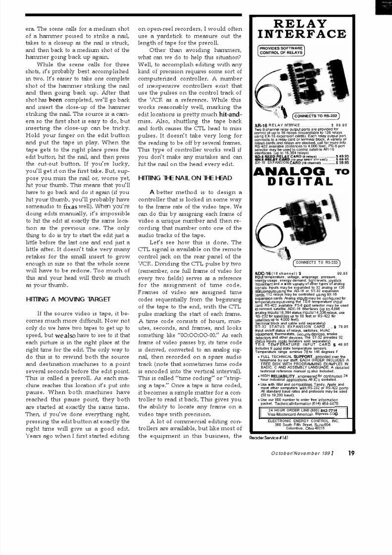
Figure 2-A simp lified bloc k d iagram of the AT&T V540 digital telephone CODEC.
section. This circuit is connected tothe T7250B line transceiver section.The physical interface for ISDN basicaccess is provided via an &position
RJ-45 modular jack.5. PC Bus Znferface Circuitry. The
BRI adapter board is mapped into theI/O space of the PC with address lo-cations ranging from 200h to 3FFh.Data bus buffering between the localbus and the PC bus is provided by abidirectional bus transceiver. Addressdecoding for chip selects and devicecontrol signals are also provided inthis section.
VOICE PORT WITH SPEAKERPHONEFUNCTIONALITY
The AT&T T7540 digital tele-phone CODEC (Figure 2) providesthe flexibility needed to support a va-riety of analog voice ports. Audiofunctions include a CODEC-filter fea-turing CL/ A-Law companding. Addi-tional voice port functions includeprogrammable touch-tone (DTMF)generation and ringer tone genera-
tion. The device also contains a pro-grammable sidetone insertion inter-face. The T7540 is controlled via anexternal microprocessor.
The T7540 has a serial interfacefor digitized voice, a parallel inter-face for microprocessor control, andthree pairs of differential analog au-dio interfaces to the handset, hands-free speakerphone, and auxiliaryequipment such as answering ma-chines or alerters.
The serial KM interface for digi-tized voice is a fullduplex serial time-
division-multiplexed bus. This serialhighway is programmable and ac-cepts variable data rate clocks rang-ing in frequency from 64 kHz to 4.096
MHz. The serial highway interfaceconnects directly to most PCM buses.In our design, the KM interface con-nects directly to the T725OB ISDN Sinterface chip. The parallel micropro-cessor interface of the T7540 is flex-ible and is interfaced easily with Intelor Motorola microprocessors. In ouradapter board design, the PC micro-processor (80x86) controls the trans-fer of information in and out of theprogrammable internal registers of
the T7540.The three analog audio interfaces
of the T7540 are the handset, hands-free, and auxiliary interfaces. Each ofthese interfaces consists of a differen-tial input and a differential output.The handset and auxiliary outputs candrive a 300-Q load directly and areprogrammable from +0 to -23.25 dBin increments of 0.75 dB. The speakeroutput can drive a 50-Q speaker di-rectly and is adjustable over a 69-dB
range in 1.5-dB steps.The T7540 provides the function-
ality needed to support microproces-sor-controlled hands-free speaker-phone operation. The microprocessormonitors and controls the system insuch a way that the coupling fromthe speaker to the microphone andpoor hybrid matching does not resultin oscillations, ringing, or unpleasantechoes.
The T7540 provides signal moni-
toring of the transmit and receivepaths. Received signals may be ex-
amined over the entire channel band-width or an 800-Hz second-orderhigh-pass filter can be selected. Speechtends to have a large part of its en-
ergy above 800 Hz, whereas roomnoise has a significant part of its en-ergy below 800 Hz. Selecting the 800-Hz high-pass filter will reduce theneed for gain switching due to noise.
To reduce the amount of micro-processor overhead required to moni-tor the voice signals, maximum-valueregisters are provided on the T7540to obtain an envelope of the receivedand transmitted voice signals. Thesemaximum-value registers retain the
highest value of the, received signalsince the last register read was per-formed. The maximum-value methodcan provide a reasonable representa-tion of the signals for a period of sev-eral milliseconds. The time requiredbetween register reads depends onthe hands-free algorithm developedby the user. Figure 3 shows how theT7540 is wired on the BRI adapterboard.
DATAPORT INTERFACE
Data transfer on the ISDN B2channel is supported by the T7121. Itconnects the serial communicationlink carrying High-level Data LinkControl (HDLC) bit-synchronous dataframes to the host PC. There is anoptional transparent mode of opera-tion in which no HDLC processing isperformed, allowing the use of otherprotocols (Figure 4). The T7121 com-
municates with the PC as an I/O-mapped peripheral and is controlled
October/November 199 J 47

8/13/2019 Circuit.cellar.023.Oct Nov.1991
http://slidepdf.com/reader/full/circuitcellar023oct-nov1991 44/100

8/13/2019 Circuit.cellar.023.Oct Nov.1991
http://slidepdf.com/reader/full/circuitcellar023oct-nov1991 45/100

8/13/2019 Circuit.cellar.023.Oct Nov.1991
http://slidepdf.com/reader/full/circuitcellar023oct-nov1991 46/100
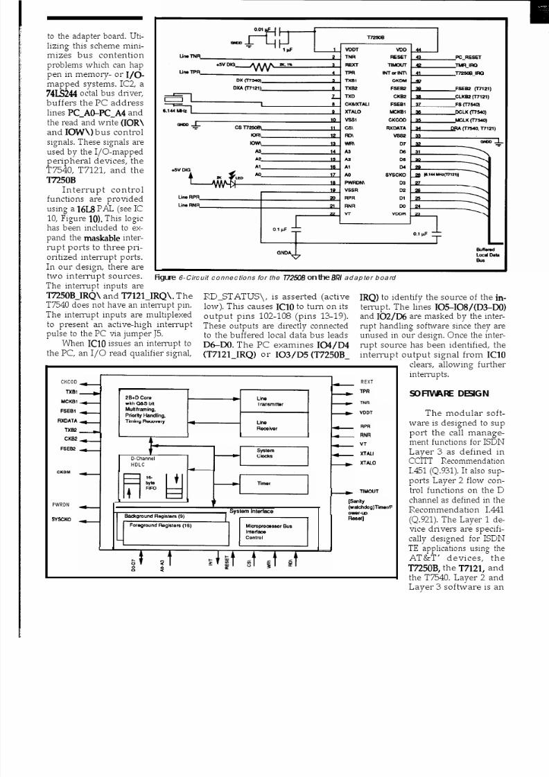
8/13/2019 Circuit.cellar.023.Oct Nov.1991
http://slidepdf.com/reader/full/circuitcellar023oct-nov1991 47/100

8/13/2019 Circuit.cellar.023.Oct Nov.1991
http://slidepdf.com/reader/full/circuitcellar023oct-nov1991 48/100

8/13/2019 Circuit.cellar.023.Oct Nov.1991
http://slidepdf.com/reader/full/circuitcellar023oct-nov1991 49/100

8/13/2019 Circuit.cellar.023.Oct Nov.1991
http://slidepdf.com/reader/full/circuitcellar023oct-nov1991 50/100
Data Call
KeyboardConversation File Transfer
Operating System Application Interface Utilities C Language
ISDN“Tr’ StateManager
INFOstateControl
Layer 3 Modu le
Call Reference Control,Packet Format Control,Layer ‘YLayer 2 Control
Layer 2 LAPDModule
Frame Buffer Queueing,Flow Control
Layer 1 Voice Port Data Port SignalingPort D e v i c eDrivers
T7121 T725OB
Bl 82I
D
I ISDN BRI Line
Figure 11 -Ge neral structure o f the software e nvironm ent.
LAPDFrame
Octet 2
Octet 3
Flag Address Control Information CR C Flag
Octet 2 is transmitted first; within each octet,the least-significant bit (LSB) is the first bit
Figure 12--7he bit fields of an LfJAD frame contain c omp l e t e ad dress, control, and da ta n
f o rmat ionp lusCRCer ro r check -
i ng.
SAPI=Service Access Point Identifier TEI = Terminal Endpoint Identifier C/R = Command/Response BitEA = Extension Address (O=extend; I= Final)
nI?.
6
October /November 199 I 55

8/13/2019 Circuit.cellar.023.Oct Nov.1991
http://slidepdf.com/reader/full/circuitcellar023oct-nov1991 51/100
the protocol control diagrams of theQ.931 standard. Each subblock istreated as an independent task underthe control of the application programinterface and TE state manager. Thefunctional signaling supported in theLayer 3 module has been tailored forthe services offered by the AT&T 5ESS
central office switch. Layer 3 softwareto support new supplementary ser-vices or to support other central of-fice switches requires some custom-ization. Such customization is avail-able from third-party vendors suchas Link Technology, Holland, Pa., andDGM&S, Mt. Laurel, NJ. Since oursoftware was very coarse and onlyserved to test our design, we feel itwould cause more problems than itwould solve to release it.
INTEGRATED VOICE/DATA ADAPTERBOARD SUMMARY
The ISDN adapter board designoutlined here provides a low-cost,high-performance terminal endpoint.This board allows users to simulta-neously access both voice and dataservices of an ISDN BRI line at the Sor T reference point. The PC plug-inboard can operate in any IBM-com-patible computer using the industry-standard architecture (ISA).
A four-layer printed circuit boardwith the functionality outlined in thisarticle has been prototyped andtested. The adapter board design pro-vides the audio functionality neededin a digital telephone or an integratedvoice-data workstation. Software run-ning on this hardware platform sup-ports not only the Layer 1 “devicedrivers” but also the CCITT standards1.441tQ.921) and 1.451(Q.931) for Lay-ers 2 and 3. The user interface is viawindow-driven menu options whichare very flexible and easy to use. Thisboard allows users to quickly learnabout the T7540 digital telephoneCODEC providing speakerphonefunctionality, the T725OB ISDN BasicRate Interface “s” transceiver, and theT7121 HDLC formatter.
For additional information anddocumentation on the devices out-lined in this article, contact AT&T Mi-croelectronics at (800) 372-2447. $P
56 ClRCUll CEl LA R INK
Steven Strauss is a licensed Professional Engi-neerandamemberoffhetechnicalstaffat
AT&T Bell Laboratories in Allentozun, Pa.,specializing in communications devices. Heholds a B.S.E.E. from Pennsylvania StateUniversity and an M.S.EE from Rensselaer Polytechnic Institute in Troy, N.Y.
P.K. Govind is a distinguished member of the
technical staff at AT&T Bell Laboratories in Allentown, Pa. He is an application wnsult-ant for communication a evices and has exten-siue experience in product planning, systemintegration, and product akvelopment. Mr.Govind received an M.S. and Ph.D. in physics
from the Unimsity of Colorado, Boula r,Colo.
REFERENCES
1. T7540 Preliminary Data Sheet,D X9-148SMOS. AT&T Micro-electronics, 1991.
2. T725OB Advance Data Sheet,DS89083SMOS. AT&T Micro-electronics, 1989.
3. T7121 Data Sheet, DS90-
087SMOS. AT&TMlcroelectfon-Its. 1990.
IRS4 10 Very Useful411 Moderately Useful412 Not Useful
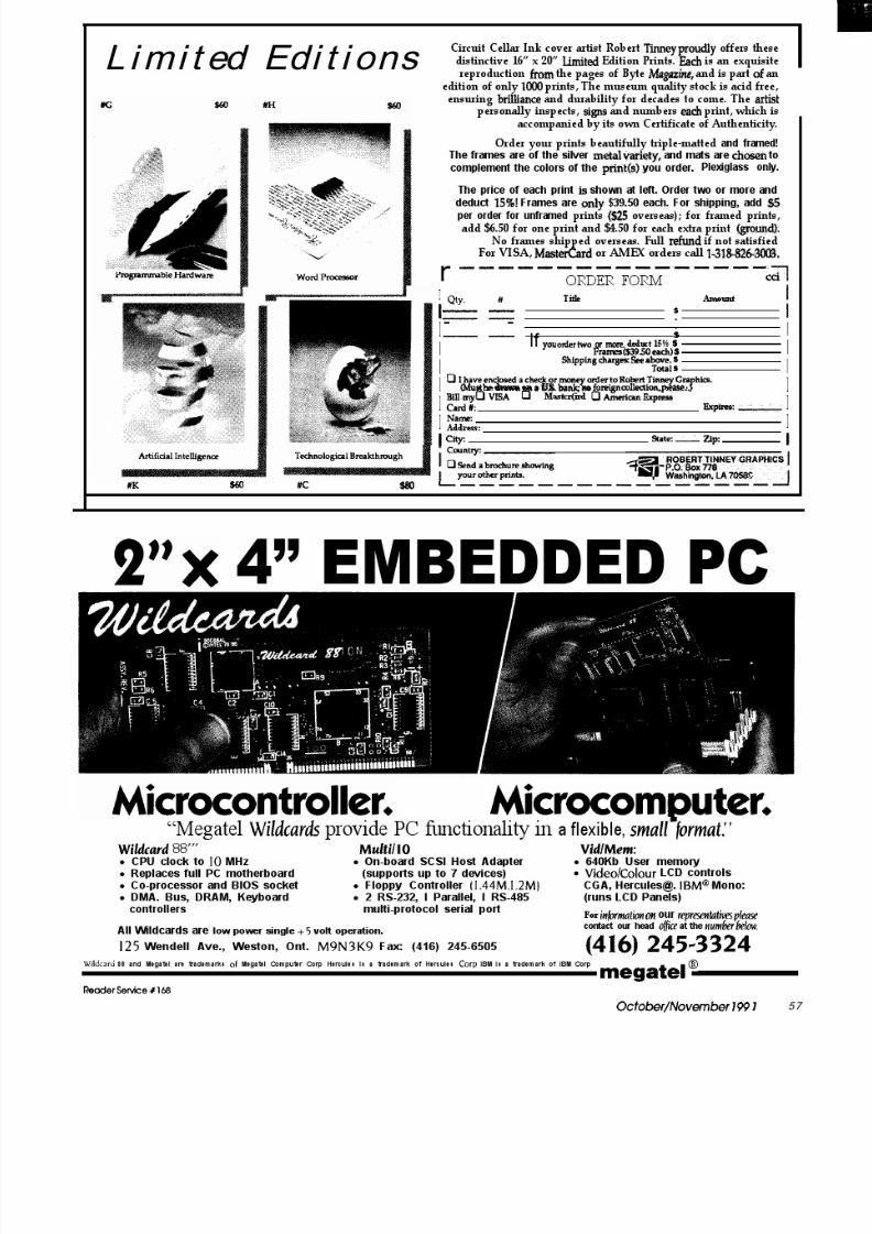
8/13/2019 Circuit.cellar.023.Oct Nov.1991
http://slidepdf.com/reader/full/circuitcellar023oct-nov1991 52/100

8/13/2019 Circuit.cellar.023.Oct Nov.1991
http://slidepdf.com/reader/full/circuitcellar023oct-nov1991 53/100

8/13/2019 Circuit.cellar.023.Oct Nov.1991
http://slidepdf.com/reader/full/circuitcellar023oct-nov1991 54/100
I.4
c l4
OrCAD Schematic Design ToolsA Wo rking Eng ine e r’s Im p ression
b y Bruc e Web b
Schematic Capture with Schemab y Ken Da vid son
October/November 199 1 59

8/13/2019 Circuit.cellar.023.Oct Nov.1991
http://slidepdf.com/reader/full/circuitcellar023oct-nov1991 55/100
SPECIALSECTIONBmce Webb
OrCADSchematic Design ToolsA Wo rking Eng ine e r’ s Im p re ssio n
L ike a lot of people, I stuffed making
printed circuifs with dr f t ing tape nd
“rub-on” pads. Not content with such crude techniques, I started investigating what
w s available to computer ize the process.
So, f ive years go I tr ied using a general-
purposeCADprogrum.
Then I got a printed circuit layout
program (Tango from Accell Tech-nologies). Last year my companybought an autorouter and schematiccapture software. Each upgrade madethe job a little easier, a little faster, andmore accurate. The last improvementturned out to be the most profound.Getting the schematic into the com-puter makes a big difference.
The process of printed circuit lay-out involves four basic steps:
1) Design the circuit (draw sche-matic)
2) Place parts on board3) Route connections (manual
and/or auto)4) Check board against schematicSchematic capture programs per-
form or assist with three of the four:designing, routing, and checking. Thehardest part for me has always beenmaking sure that the printed circuitmatches the schematic before I spendthe timeand money fabricatingboards.That is where schematic capture makesa big contribution.
60 CIRCUIT CELLAR INK
ORCAD
OrCAD Schematic Design Tools(SDT) is a low-cost schematic captureprogram which may be used withother design products as part of acomplete printed circuit design pack-age or alone to create standard andeasy to read schematic diagrams.
OrCAD SDT is not a single pro-gram; it is a collection of programs (or“tools”) that provides a way for theuser to create, edit, check, and printschematics. It requires a minimum offive megabytes of hard disk space onan IBM-compatible computer with atleast EGA graphics, 640K or more ofRAM (EMS supported), and a mouse.The results of your efforts may beprinted on most popular printers oron an HP-compatible plotter. I use a16-MHz80286machinewith4Mbytesof RAM, a super VGA display, and anHP-compatible laser printer. I useTangoPCB and autorouter to createPC board layouts from OrCAD netlists.
The heart of the OrCAD SDT soft-ware is a drawing program calledDRAFT. DRAFT starts with a blankdrawing sheet that includes a titleblock where company name, sche-
matic title, revision date, and so on arestored. The title block is not just anarea on the drawing; it is a kind ofheader that makes it easy to keep trackof your documents. A pull-down win-dow provides access to the DRAFT
commands. The operation is intuitive,though some time with the manualmay keep the user from confusingcommands.
DRAWING FEATURES
Drawing a schematic is as simpleas retrieving the parts that make upthe design from libraries and connect-ing them with lines or “wires” on thescreen. OrCAD also allows groups ofwires to be collected into buses tomore easily get the connections fromone area of the schematic to anotherwithout cluttering. Special connectionssuch as power or ground are made tonodes which are implicitly connected.The process elements are pretty muchthe same as hand drawing, except thelines stay straight without a ruler.
Large schematics may be dividedinto sheets with either a flat or hierar-chical structure. Connectionsbetweensheets are accomplished using mod-ule ports. The flat structure has thesame level of detail on all sheets. In ahierarchical structure, the detailedlower levels of the drawing are repre-sented as blocks at levels nearer thetop.OrCADSDTallowsblocksofsche-matics which are repeated in the de-

8/13/2019 Circuit.cellar.023.Oct Nov.1991
http://slidepdf.com/reader/full/circuitcellar023oct-nov1991 56/100
signtobeshownonceonasingle sheetand then referred to by a block desig-nation. The more complex your sche-matic, the more you will appreciatethe completeness and flexibility ofthese structures. Fortunately, if yourneeds are simpler, these options donot get in the way.
LIBRARIES
Only the libraries you use need tobe installed. There is no point in hav-ing OrCAD search through digitalcomponents if your design will onlyuse analog parts. Components not
Schematic versions of electricalcomponents are stored in SDT’s ex-
available in OrCAD libraries can be
tensive libraries of more than 20,000parts. The components are rectangles
made from existing parts or built from
or logic shapes with the “pins” repre-sented as lines. Each pin is labeled
scratch. I have created, for example, a
with its function name. Using libraryparts relieves the user from the effort
complete library of my own of Maxim
of redrawing them, and since the li-
braries have been debugged by years
interface and microprocessor control
of use, it is unlikely that you’ll en-counter any mislabeled or missing
components that OrCAD didn’t in-
pins. The libraries are organized byfamilies such as CMOS, ‘ITL, or ana-
clude. I also created special RAM/
log, and by manufacturer such asMotorola or Intel.
ROM chips for designs where either
SCHEMATIC CAPTURE SOFFWARE EECAD)
an EPROM or static RAM (like 2764 or6264) can be installed.
One of the hardest skills I havelearned in drawing schematics is pre-dictinghowmuchspacewillbeneededbetween components for wires to run.Moving a part to another area on theschematiccanbedonesothatthewires
move with it, but the results are usu-ally messy and have to be redone more
pins wired to a third could be con-nected together directly. Power andground lines are generally tied tonodes which are implicitly connectedto keep the drawing less cluttered.
The net list provides a way tocommunicate the schematic connec-tions to a PCB layout program. All of
the connections are then routed eitherby hand or using an autorouter. I pre-
OCAD b oa sts 50,000 users and ha ve de velop ed suppo t f
for them that I found to b e reasona ble a nd c lear . The re
has alwa ys be en som eo ne a t the other end when I ca t t ed
and if the person I first rea c hed c ouldn ’ t help, I wa s c a lled
ba c k w ithin a few hours with the a nswe rs.
than once. I usually try to completesmall blocks of schematic and place
A schematic capture program
them rather than placing individualparts. This is also a good idea when
helps you to draw an easy-to-read and
placing parts on the PC layout. Youhave a schematic. Now what?
somewhat standard drawing, but thereal magic is what happens once theschematic is complete. The schematic
can be used to create a file of thedrawing’sconnectionscalled a net list.The net list is an ASCII listing of all ofthe wires on the schematic with theendpoints of each being a componentpin. The connections are grouped to-gether into nets. The grouping is im-portant because it recognizes that two
fer to route most boards by hand andthen check my work using theautorouter.Checkingcanbe thereallyhard part to do by hand! When theprocess is complete, there will be aschematic diagram that exactlymatches the printed circuit board andvice versa.
Having an accurate and verifiedschematic is an extremely valuabletool for someone trying to modify or
debug a circuit-ven if that someoneis the original designer!OrCAD SDT can create a number
of reports related to the design. Theyinclude a parts list, designation list(Ul is an 8031), and so on, that helpensure compatibility between theprinted circuit and the schematic.
A typ ica l d raw ing ma de w ith OrCAD m ight inc lude ind iv idua l ga tes, co mp lete ch ips, and bused signa ls. This sam ple w as O U t p U t On 7
p lo t te r w ith a line - t ipp ed pe n .
Oc tober /Novem be r 199 1 61

8/13/2019 Circuit.cellar.023.Oct Nov.1991
http://slidepdf.com/reader/full/circuitcellar023oct-nov1991 57/100
SETTING UP
OrCAD has chosen to use an in-stall program for setup and to trans-mit updates. There is a total of fourl.ZM-byte floppy disks on which thesoftware has been archived (com-pacted). One of the disks marked “IN-STALL” is placed in A: drive and theuser types the word INSTALL fromthe prompt. The install program asksquestions about hardware and libraryrequirements to customize the sys-tem. Nothing could be easier. The pro-grams are installed in a well-orga-nized way in several subdirectoriesandchangesaremadeto~~~~~~. SYSand AUTOEXEC . BAT automatically.
The programs come with fivemanuals including: Installation andTechnical Support Guide,OrCADSDTUser’s Guide, OrCAD ESP Environ-ment User’s Guide, Text Editor User’sGuide, and OrCAD SDT Reference.
The manuals alone are not par-ticularly helpful if it is the first timeusingschematiccapturesoftwaresincesome of the lingo can be confusing. It
isdifficulttodistinguishbetweenwhatmight have been problems with thedocumentation and my limited un-derstanding of the design process andimpatience when I started usingOrCAD. I needed the software rightaway, so I began by drawing somesimple designs and working things
out with the Reference Manual inhand. I don’t recommend reading allthemanualsbeforestarting. Itisbetterto jump right in and then go back laterto learn some of the finer points.
A sample schematic is includedwith the program and is discussed inthe user’s guide. Following the tuto-rial with the manual in hand is veryhelpful, but cannot cover all of thetopics encountered when designing areal schematic for a project.
ORCAD’S LATEST EFFORT
My one major complaint aboutOrCAD SDT when we first purchasedit was that each program of the collec-tion had to be invoked from the DOScommand line with whatever switches
and file names were appropriate. Forexample:
NETLIST MYBOARD SCH
C:DESIGN\MYBOARD.NET /S
is the command to create a net listfrom a drawing called MYBOARD. SCH
and place the fileMYBOARD. NET)
insubdirectory c : \DESIGN. The satthe end signifies that the file should bewritten in the format for the TangoPCB program that I use for layout. Itrequired great feats of memorizationfor those who didn’t use it every day,or lots of looking through the manual.
OrCAD has recently improved thesoftware (Release IV) to include anintegrated windows-style environ-ment that they call ESP. On-screen‘buttons” are used to select programsand set up options. The programswitches are replaced by setting up alocal environment with the switchesset as defaults. The result is an intui-tive user interface that works well.
The new environment is not per-fect, though. The programs are not
Easy to Use PC Software - ICON Based - Mouse DrivenUltra Fast Performance - Advanced Editing Tools
Output to Printers, Plotters Lasers
ISlSDESlGNER is the Schematic Capture for anyoneneeding to enter designs. Provides netlist, multi-sheet,user configurable partslist & Electrical Rules Check report.
BBEs PCBA new autorouter uses an advanced multi-strategy to achieve very high connection rates & it’s fast!10 copper layers, Design Rule Checker and MORE.
R4 SYSTEMS Inc.P.O.Box 451West Hill, OntarioCanada .Ml E 4Y9 (416) 439-9302
Download DEMO from BBS at 416 289-4554 (2400/8/N/l)
Readerservice 1194
The Micro’IYacker’” can significantly reduce thecost of your next real-time product development project. Advanced features speed software devel-opment and enhance quality assurance.FEATURESW 2K or 8K Trace Memoryn Interval Timer
n Instruction Disassemblyfor 280. 8085, 6502,
n Performance Analysisn FE-232 Interfacen IBM PC Softwaren Symbolic Disassemblyn Low Cost from $1295.
6802, 6809,8031/8051, 80188/80186,V4ON50
ll for Free Brochure
62 CfRCfJfl CELLAR INK
8/13/2019 Circuit.cellar.023.Oct Nov.1991
http://slidepdf.com/reader/full/circuitcellar023oct-nov1991 58/100

8/13/2019 Circuit.cellar.023.Oct Nov.1991
http://slidepdf.com/reader/full/circuitcellar023oct-nov1991 59/100
8/13/2019 Circuit.cellar.023.Oct Nov.1991
http://slidepdf.com/reader/full/circuitcellar023oct-nov1991 60/100
SPECIALSECTION Schematic CaptureKen Davidson
with SchemaI
So what’s wrong with notes on paper napkins? Sure, they can be a little
mushy to write on, and you can’t fit a whole lot onto one, but they travel real
well, and once you’re done with them, you can use them to wipe the sweat
from your brow.
Steve tells stories of the “good old days” when he could sketch out a circuit
on a dinner napkin, bring it down to Ray Long’s to have a board laid out (see
“Bringing in the Pros” in issue 20 of C IRCUIT CELLAR INK for more on Ray’s
company), and have a working board in hand in short order.
Those were also the days whenCircuit Cellar projects tended to beess complex. The PC boards were allaid out by hand using several layers
of acetate, rub-ons, tape, and a good,harp knife; circuit designs were san-ty checked by the designer’s keen eye
and perhaps an associate looking overhis shoulder; and the person layingout the PC board had to be able tomanually swap gates within a pack-age or catch a bad pin number on thechematic. Invariably, when the pro-otype PC board came back for firstest and didn’t work, at least half ofhe problems could be attributed toayout mistakes.
About six years ago, we startedooking for a better way. Reasonably
priced schematic capture packageshat might be considered for serious
professional use were just starting tohow upon themarket. Wealso started
working on Ray to upgrade his shop,rying to convince him that his pro-
ductivity could jump markedly if hewere tocomputerize. Up to that point,here wasn’t a piece of silicon to beound in his shop.
ClRCUlJ CELLAR INK
Omation Inc. was trying a novelidea for the software industry: a freedemo disk containing a version of thesoftware that was fully functional ex-cept for some key features such assaving or printing. We gave them acall, received the disk, and have beenusing Schema for all our schematicsever since.
SCHEMATIC CAPTURE SOFlWARE
Before I get into Schema proper,let me go over a few schematiccapturebasics. There are two key questions toask when looking at any software:what will the software do for me thatI either can’t do now, can’t do effi-ciently, or can’t do effectively (i.e.,how will it save me time?); and is iteasy enough to use that I’ll continue touse it and not be hindered by it?
Foranyonenotfamiliarwithsche-matic capture packages, it is useful toconsider the idea that they are to cir-cuit design what word processors areto writing. A good word processordoes not make a good writer (as I’moften reminded), but a good writer
can often dramatically improve hisproductivity by using a good wordprocessor. He is able to shed many ofthe more mundane and error-pronetasks onto the computer and direct allhis energies to actually writing.
Most of the designer’s (writer’s)time will be spent entering new infor-mation and manipulating and modi-fying it. This stage is where a gooduser interface is a must. If the designerhas to labor at using the computer, it’snot going to save him any time andhe’ll be less likely to use it in the fu-ture. All schematic capture packagesI’veseenuseagraphicalinterfacewithat least one on-screen menu and support (if not require) the use of a mouse.They allow the designer to manipu-lateeverythingassociated withacom-ponent as a single unit. For example,the outline of the part, the pin num-bers, and the pin descriptions are allintegrated. Individual components orgroups of components may be movedanywhere on the screen and wire con-nections may be changed at any time.
Humans are the only ones whocan lookat a design to determine if it’s

8/13/2019 Circuit.cellar.023.Oct Nov.1991
http://slidepdf.com/reader/full/circuitcellar023oct-nov1991 61/100
SCHEMATIC CAPTURESOFWARE EECAD)
going to work, but the computer canoften helpcatch theobviousmistakes.A good piece of schematic capturesoftware will do a “design rule check,”which is akin to the spelling checkerfound in most word processors. (Theword processor won’t tell you whetherthe critics will like your piece, but it
can at least make sure you’re usingwords from the English language.)The design rule check looks for suchblundersasmultipledriversconnectedtogether, inputs left floating, multiplecomponents with the same referencedesignator, and labels used in onlyone place.
PC board layout software to ensureaccurate transfer of the design fromthe symbolic schematic stage to thephysical hardware stage. Similarly,word processors often support nu-merous file formats to ease the transi-tion from, for example, the author’sIBM PC to the publisher’s Macintosh.
Schema includes full mouse support. While not required, you’d haveto be a fool not to use one.
SCHEMA: THE SCREEN
Once your design is complete, youmay elect to print or plot the finishedproduct. Most schematic packagessupport at least HPGL pen plotters
and dot matrix printers. Most alsosupport a broader range of plottersplus laser printers. Likewise, mostword processors have a list of sup-ported printers longer than their listof supported features.
The majority of the screen is con-sumed by the main drawing area.Downtheleft sideisamenu, thetopofwhich always contains the top-levelcommands while the bottom changes
depending on what command hasbeen selected. At thebottomleftof thedrawing area is an optional screencoordinate box that is continuouslyupdated with the current location ofthe cursor. Many different displayadapters are supported, including allthe major super VGA boards. It was apleasure to upgrade from a vanillaCGA to an 800 x 600 VGA display.One of the 1024 x 768 boards on themarket would provide an even larger
window onto the schematic beingdrawn.
PART DEFINITIONS
In order to aid in the transfer ofyour finished design to the next stage,most schematic capture packages alsosupport the generation of a “net list’(which is usually the reason for usingthe software in the first place). Any
connectionbetweentwoormorecom-ponents is called a “net.” A net list isnothing more than a list of compo-nents on the board and a list of con-
When we received the demo diskand tried out the package, the moststriking feature at first glance was itsuser interface. Most drawing pack-ages allow you to see only a staticview of your drawing and force you touse scroll bars or awkward keyboardcommands to move to other parts ofthe schematic. With Schema, when
thecursorreachesanedgeofthedraw-ing area, the whole area starts tosmoothly and quickly scroll across theschematic, stopping either when thecursor is moved away from the edgeortheedgeoftheschematicisreached.With such a feature, the designer canvery easily move from one part of theschematic to another without lifting afinger or moving the cursor very farfrom the area of interest. It also elimi-nates the frustratingly slow screen
redrawsoftenencounteredwithdraw-ing packages. If you want to get abetter feel for what the drawing lookslike as a whole, a number of zoom
The first step in drawing any sche-matic is defining the components.Omation includes extensive librariescontaining all the popular logic fami-lies (LS, CMOS, etc.), microprocessors,memory, and, of course, active andpassive analog components, so
chances are most of the parts you’llwant are already defined. For thosethat aren’t, or if you’re not happy withthe predefined version, you can go to
nections between them. It is used by levels are supported. the object editor.
AO-A15 u3
\ 6264
\a12 m
<All 23 CIIIz
ENABLE1 74115138
I_Al
A0 9Al
I0 A0WRITE 27
R\W
+5 26 -CEZ
200CElREAD 2200E
Com par ing the sam e c i rcu i t be twe en Sche ma and OrCAD show s that both prog ram s ge t the job d one , but eac h has its own SW/e.
Sc hem a’s output w as do ne o n a n HP LaserJet p r in ter.
Oc tobe r /Novembe r W 65
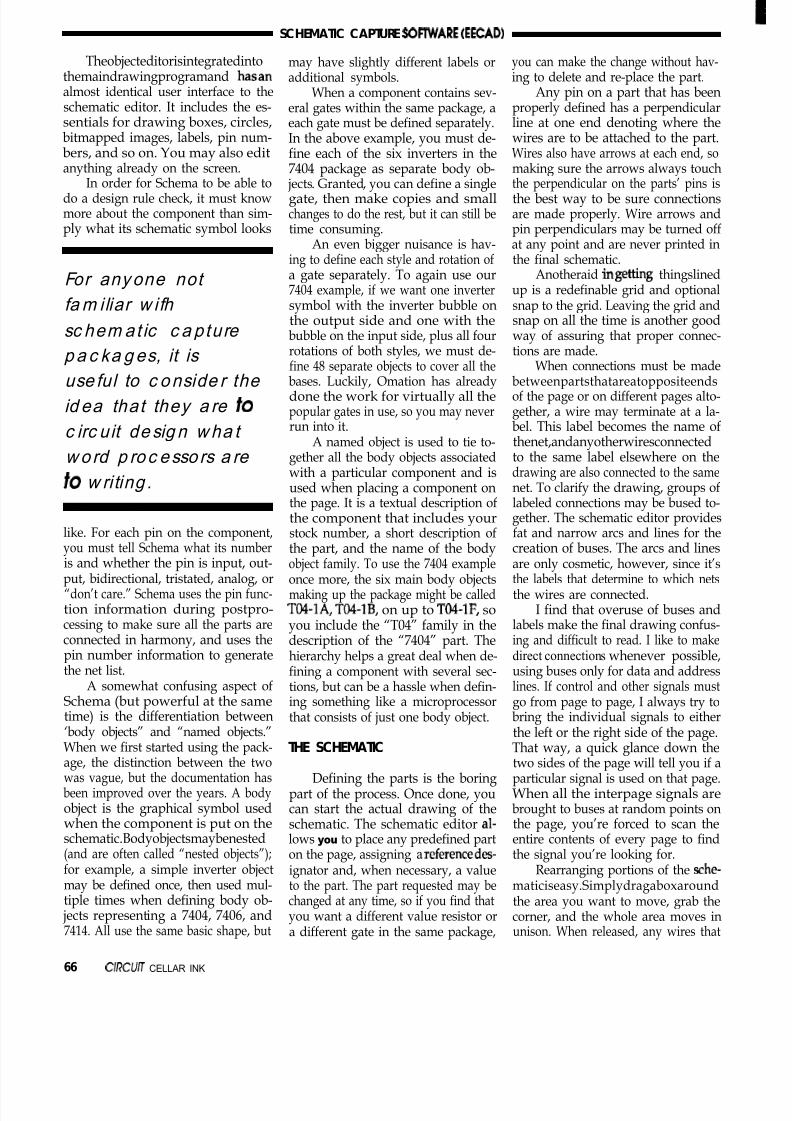
8/13/2019 Circuit.cellar.023.Oct Nov.1991
http://slidepdf.com/reader/full/circuitcellar023oct-nov1991 62/100
SCHEMATIC CAPTURE SOFtWARE EECAD)
Theobjecteditorisintegratedintothemaindrawingprogramand hasanalmost identical user interface to theschematic editor. It includes the es-sentials for drawing boxes, circles,bitmapped images, labels, pin num-bers, and so on. You may also editanything already on the screen.
In order for Schema to be able todo a design rule check, it must knowmore about the component than sim-ply what its schematic symbol looks
For anyone not
fam iliar w ifh
sc hem at ic c a pture
p a c ka g es, it is
use ful to c onside r the
id ea that they a re fo
c irc u it de sig n wha t
wo rd p roc esso rs a re
fo w riting .
like. For each pin on the component,
you must tell Schema what its numberis and whether the pin is input, out-put, bidirectional, tristated, analog, or“don’t care.” Schema uses the pin func-tion information during postpro-cessing to make sure all the parts areconnected in harmony, and uses thepin number information to generatethe net list.
A somewhat confusing aspect ofSchema (but powerful at the sametime) is the differentiation between
‘body objects” and “named objects.”When we first started using the pack-age, the distinction between the twowas vague, but the documentation hasbeen improved over the years. A bodyobject is the graphical symbol usedwhen the component is put on theschematic.Bodyobjectsmaybenested(and are often called “nested objects”);for example, a simple inverter objectmay be defined once, then used mul-tiple times when defining body ob-
jects representing a 7404, 7406, and7414. All use the same basic shape, but
may have slightly different labels oradditional symbols.
When a component contains sev-eral gates within the same package, aeach gate must be defined separately.In the above example, you must de-fine each of the six inverters in the7404 package as separate body ob-
jects. Granted, you can define a singlegate, then make copies and smallchanges to do the rest, but it can still betime consuming.
An even bigger nuisance is hav-ing to define each style and rotation ofa gate separately. To again use our7404 example, if we want one invertersymbol with the inverter bubble onthe output side and one with thebubble on the input side, plus all fourrotations of both styles, we must de-
fine 48 separate objects to cover all thebases. Luckily, Omation has alreadydone the work for virtually all thepopular gates in use, so you may neverrun into it.
A named object is used to tie to-gether all the body objects associatedwith a particular component and isused when placing a component onthe page. It is a textual description ofthe component that includes yourstock number, a short description of
the part, and the name of the bodyobject family. To use the 7404 exampleonce more, the six main body objectsmaking up the package might be calledTM-lA, TO4-lB, on up to TO4-lF, soyou include the “T04” family in thedescription of the “7404” part. Thehierarchy helps a great deal when de-fining a component with several sec-tions, but can be a hassle when defin-ing something like a microprocessorthat consists of just one body object.
THE SCHEMATIC
Defining the parts is the boringpart of the process. Once done, youcan start the actual drawing of theschematic. The schematic editor al-lows you to place any predefined parton the page, assigning a referencedes-ignator and, when necessary, a valueto the part. The part requested may bechanged at any time, so if you find that
you want a different value resistor ora different gate in the same package,
you can make the change without hav-ing to delete and re-place the part.
Any pin on a part that has beenproperly defined has a perpendicularline at one end denoting where thewires are to be attached to the part.Wires also have arrows at each end, somaking sure the arrows always touch
the perpendicular on the parts’ pins isthe best way to be sure connectionsare made properly. Wire arrows andpin perpendiculars may be turned offat any point and are never printed inthe final schematic.
Anotheraid in getting thingslinedup is a redefinable grid and optionalsnap to the grid. Leaving the grid andsnap on all the time is another goodway of assuring that proper connec-tions are made.
When connections must be madebetweenpartsthatareatoppositeendsof the page or on different pages alto-gether, a wire may terminate at a la-bel. This label becomes the name ofthenet,andanyotherwiresconnectedto the same label elsewhere on thedrawing are also connected to the samenet. To clarify the drawing, groups oflabeled connections may be bused to-gether. The schematic editor providesfat and narrow arcs and lines for the
creation of buses. The arcs and linesare only cosmetic, however, since it’sthe labels that determine to which netsthe wires are connected.
I find that overuse of buses andlabels make the final drawing confus-ing and difficult to read. I like to makedirect connections whenever possible,using buses only for data and addresslines. If control and other signals mustgo from page to page, I always try tobring the individual signals to either
the left or the right side of the page.That way, a quick glance down thetwo sides of the page will tell you if aparticular signal is used on that page.When all the interpage signals arebrought to buses at random points onthe page, you’re forced to scan theentire contents of every page to findthe signal you’re looking for.
Rearranging portions of the sche-maticiseasy.Simplydragaboxaroundthe area you want to move, grab the
corner, and the whole area moves inunison. When released, any wires that
66 CIRCWJ CELLAR INK
8/13/2019 Circuit.cellar.023.Oct Nov.1991
http://slidepdf.com/reader/full/circuitcellar023oct-nov1991 63/100
crossed into or out of the moved areaare still connected, though often endup as diagonal lines that must later besquared off and cleaned up. The ad-vantage of this “rubberbanding” ef-fect is that once you make a connec-tion with a wire, that connection isnever broken until you delete the wire.
It’s just one more way that the com-puter can be used to keep track of thelittle details while you concentrate ondoing the design.
As I mentioned when describingthe object editor, support for rotatedparts is pretty slim. Recent versions ofSchema include a rotate command inthe draw and edit menu entries, butthe command relies on the existenceof rotated versions of the part in one ofthe libraries. If a rotated version hasn’t
been defined, one must be definedbefore a rotation can take place.
Scaling isn’t supported atall. Oncean object has been defined, its sizecan’t be changed unless you go intothe object editor and redefine it. Un-less you’re trying to fit a D-size draw-ing onto a B-size page, I don’t thinkyou’ll miss scaling.
POSTPROCESSING AND PRINTING
Once the drawing in complete,there is a host of postprocessing thatmaybedone toit. While theobjectandschematic editors described above areintegrated into one program, the restof the Schema package consists of sepa-rateprogramsforeachpostprocessingtask.
As I mentioned before, a designrule check may be done to look forsilly drawing mistakes. A list of parts,sections within each part, and refer-
ence designators may be produced, aswell as a complete bill of materialswith your own stock numbers next toeach component. The net list may alsobe generated at this point.
Almost all PC board layout pro-grams use their own net list format.Omation includes a very useful utilitythat converts their net list format tothose used by the major PC boardlayout programs and systems. Ourlayout house (Custom Photo) pur-
chased a Calay system in response toour prodding, so the final step we
Ten microwatts.
Less money, lesspower, less time,less work.To place an order, or for more information, call:
1-800-GET-DATA (438-3282)
1-602-996-0255/fax
With its automatic power cycling, that’s theaverage power draw of the nanoLlNKController/Peripheral in a typical application. Noextras--it’s all built-in and can be enabled withone instruction. Run your application for over
two years on a 9V battery, or forever on athumb-sized solar cell. And because the nanoLlNK Controller/Peripheralwas designed to function as a PC peri
8heral--no
programming required--OR as a stan -alonecontroller, you can use it on the bench, in thefield, or both. 8 A/D inputs, 32 l/O lines, 1Apower & PWM outputs, and much more.
A full-function BIOS is included--no devicedrivers to write. A typical data-loggingapplication requires less than a dozen lines of code. And an interactive editor & macroassembler is included--no expensive crossdevelopment tools to buy.
And the price? $395, quantity l--call today.
nano Power -l-Es A dklskm d AlrDlgltd Corporatl~n
L l
Position and/or Velocity
M t i b n Cb lWlllllllllllllllllllllllllllllllllllllllllllllllllllllill
DCX-
8 -Axis Programmable Motion tioll r
l
State-of-the-art Digital Multiiunction Controller can be configured in minutesusing “off-the-shelf” components
l DCX motherboard contains intelligence/ memory/firmware and 8 sockets for “plug-in” Modules
l 1 to 8 “plug-in” DC Servo, Stepper or Special Purpose Control Modules canbe mixed/matched on same DCX board
l Install in any PC/XT/AT compatible, or use “stand-alone” with RS232and/or IEEE-488 interface Modules
l High level interface libraries in ” C” and ” BASIC,” with examples and sourcecode, included
Precision Micro ControlC O R P O R A T I O N
8122 Engineer Road, San Diego, CA 92111(619) 565-l 500 FAX (619) 565-l 511
Reode rSe t i e 191
Oc t o b e r / No v e m b e r 199 6 7

8/13/2019 Circuit.cellar.023.Oct Nov.1991
http://slidepdf.com/reader/full/circuitcellar023oct-nov1991 64/100
8/13/2019 Circuit.cellar.023.Oct Nov.1991
http://slidepdf.com/reader/full/circuitcellar023oct-nov1991 65/100
DEPARTMENTS
Firmware Furnace
I I
From the Bench
Silicon Update
Practical Algorithms
wpuge 103
ConnecTime
e-)Starting C
OK , even I admit it now:C for microcontrollers has arrived.Whether you like it or not, if you don’tspeakCyouwon’tbeahitattheparty.Indeed, a recent RFQ arrived stating“the software will be written in the C
programming language” withoutspecifying the CPU. The handwritingis on the wall!
Rest assured that Firmware Fur-nace won’t turn into Yet Another CColumn. There are cases where as-sembly language code is still required(and I will gleefully point them out),but, for the most part, source codelistings will be in C rather than assem-bler. For us, C will serve as a “high-level assembler” rather than a “low-
level” language.During the past two years I used
Avocet C for many of my projects,some of which you have seen here.
Judging from the BBS traffic, though,the market leaders are Franklin andArchimedes. Any of these three willset you back about two kilobucks,whichisalotofcointodropin theslot,especially if you are not convinced Cis a Good Thing.
Unfortunately, switchingbetween
C compilers is not as simple as com-peting vendors would have you be-lieve, quite apart from the up-frontcost. Each compiler accepts a differentsubset of the C language, the run-timelibraries are nearly disjoint, and theassembly language interfaces are ut-terly bizarre. While “straight C code”will port, your programs won’t be-cause they will depend on featuresunique to your current compiler andassembler.
The good news is that the markethasroomformore than just thebiggies.
A cursory glance through any maga-zine catering to the firmware tradewill reveal several C compilers pricedwell under the tropopause. For thiscolumn I will use the 2500AD com-piler, which I bought earlier this year
for a specific project that didn’t suitAvocet C. It costs $600 and includesthe compiler, assembler, and an as-sembly language simulator.
While I don’t intend to start areview series, either, I will also look atthe Micro-C shareware compiler fromDave Dunfield in the next column. Ifyou thought you couldn’t afford C,the times they are a-changin’ (and forthe better, too).
IN THE BEGINNING
The C language makes severalassumptions that just aren’t true afterthe CPU emerges from a hardwarereset. For example, althoughuninitialized C variablesare supposedto be set to zero, 8051 hardware doesnot clear either internal or externalRAM before executing the instructionat address OOOOh. And the hardwarehas no idea of how to load the proper
values into C’s initialized variables,either.Obviously, all variables must be
set up before the first line of C codeexecutes, so the code that gets controlimmediately after a hardware resetcannotbe writteninc. Nomatterhowsimple the C code, some assembly isstill required!
Every C compiler package in-cludes a startup routine that must belinked with each C program to handle
these initializations. Avocet calls itCRT5lx, 2500AD refers to C8051xR,
70 C IRCUIT CELLAR INK

8/13/2019 Circuit.cellar.023.Oct Nov.1991
http://slidepdf.com/reader/full/circuitcellar023oct-nov1991 66/100
FIRMWAREFURNACE
Ed Nisley
x” marks the spot for the memorymodel identifier, which I will discusslater, so you must use the appropriateroutine for your situation.
Each company decides what func-tions should occur in the startup rou-tine. Avocet includes just memory andstack initialization, 2500AD heaves inring-buffered and interrupt-drivenserial handlers, and Micro-C just setsthe hardware stack pointer. You mustreview the contents of the file to makesure that you arenot getting too much,
too little, or the wrong kind of initial- the *RD and *WI3 signals. I/O portsization for your purposes. Contrary to are memory-mapped in the Externalpopular opinion,changing the startup data space, so there is no separate I/Ocode is not sinful-it can be essential! addressspaceasthereison8086CI’Us.
MEMORY MODELS
The 8051 architecture defines sev-eral different address spaces. Programinstructions are burned into EPROM,which is located in Code space andaccessed by the *PSEN logic signal.Variables can be in either Internal orExternal RAM, the latter accessed by
Internal RAM has only 128 bytes(in the 8052 derivatives, 256 bytes) tohold the CPU’s working registers, thehardware stack, and 128 directly ad-dressable bit variables. The workingregisters are not usually accessiblefrom the C code level. The hardwarestack may or may not hold C functionparameters, but will always hold thefunction return addresses. Bit address-
1+ c310 uF
N o t e o r d e r !
Figure l--The c ontro l ler for the sam p le LED d isp lay is a t yp ica l 8032-based c irc ui t reg ula r rea de rs shou ld b e v ery fami l iar w i f h .
October/November 199 I 71

8/13/2019 Circuit.cellar.023.Oct Nov.1991
http://slidepdf.com/reader/full/circuitcellar023oct-nov1991 67/100
ing varies by compiler; some havegood support, others none at all, whilesome have rather clumsy support thatisn’t worth using,
A further complexity arises whenexternal hardware combines theCodeand External RAM address spaces byORing the *PSEN and *RD signals.The Code space must start at addressOOOOh because that’s where the CPUbegins execution, so RAM must startat a higher address (typically 2000h or8OOOhl to avoid collisions.
Most 8051 C compilers support atleast two memory models, known asSmall and Large. The Small modeluses only Internal RAM, while Largeuses External RAM for variables andthe C parameter stack. Of course, thememory model names are not stan-
dardized and there are several per-mutationsandcombinationsavailable.For example, Micro-C’s Mediummodel corresponds to Avocet’s Large,while 2500AD uses the terms Internaland External Mode. Read the manualcarefully!
TWINKLE, TWINKLE, LED
There’s nothing like a good hard-ware project to justify some softwareexperimentation and find how thingsreally work. I’ll use the 8032 systemshown in Figure 1, which will runwith the Small memory model be-cause it has no external RAM. Figure 2shows the “output device,” a rectan-gular array of 40 multiplexed LEDs.
Each of the 40 LEDs is associatedwith a C variable located in the 8032’sInternal RAM. The firmware countsthe variable down at a regular rate.When the value hits zero the firmwareupdates the LED, turning it OFF orON as needed. The result is a pleasantblinking array that’s sure to brightenup any office decor. When you see it in
action you may be reminded of thestatus panels in those old Star Treksets...the ones before the fake large-screen CRT displays.
A jumper changes the displaymode so the LEDs blink briefly whenthe corresponding timer hits zero. This
mode ismore frenetic, suited for thoseoccasional high-caffeine days.
Listinglshows BLINKBOX S~~~~loop. There are two key data struc-tures: the Timers array holds the 40variables that determine when eachLEDchangesstateandthe~nodeDataarray, which holds the 40 bits (fivebytes)thatmapeachLED.TheDataIDand B it Ma s k variables convertTimerID into an AnodeData indexand bit location.
Although you might thinkAnodeData should be located in thebit-addressable section of InternalRAM, it turns out that the 8051 in-struction set doesn’t have a general-ized “set bit” instruction (despite whatyou might conclude from the 8051App Notes). The bit location is en-
coded in the instruction, rather thanbeing held in a register, so 120 differ-ent instructions are necessary to turn40differentLEDsonandofforcomplement their state. It is far simpler togenerate a byte index and mask insoftware and do the bit twiddling “by
8 x 3.3K
0 x 2N2907F\
8 x 3 9
5 x 4 . 7 K
FigWe 2--The f lashy pa rt of the sample c irc uit is the a rra y o f 40 1EDs ar rang ed in iv e row s and eight c olumns.
7 2 ClRCUIT C ELLAR NK

8/13/2019 Circuit.cellar.023.Oct Nov.1991
http://slidepdf.com/reader/full/circuitcellar023oct-nov1991 68/100

8/13/2019 Circuit.cellar.023.Oct Nov.1991
http://slidepdf.com/reader/full/circuitcellar023oct-nov1991 69/100

8/13/2019 Circuit.cellar.023.Oct Nov.1991
http://slidepdf.com/reader/full/circuitcellar023oct-nov1991 70/100
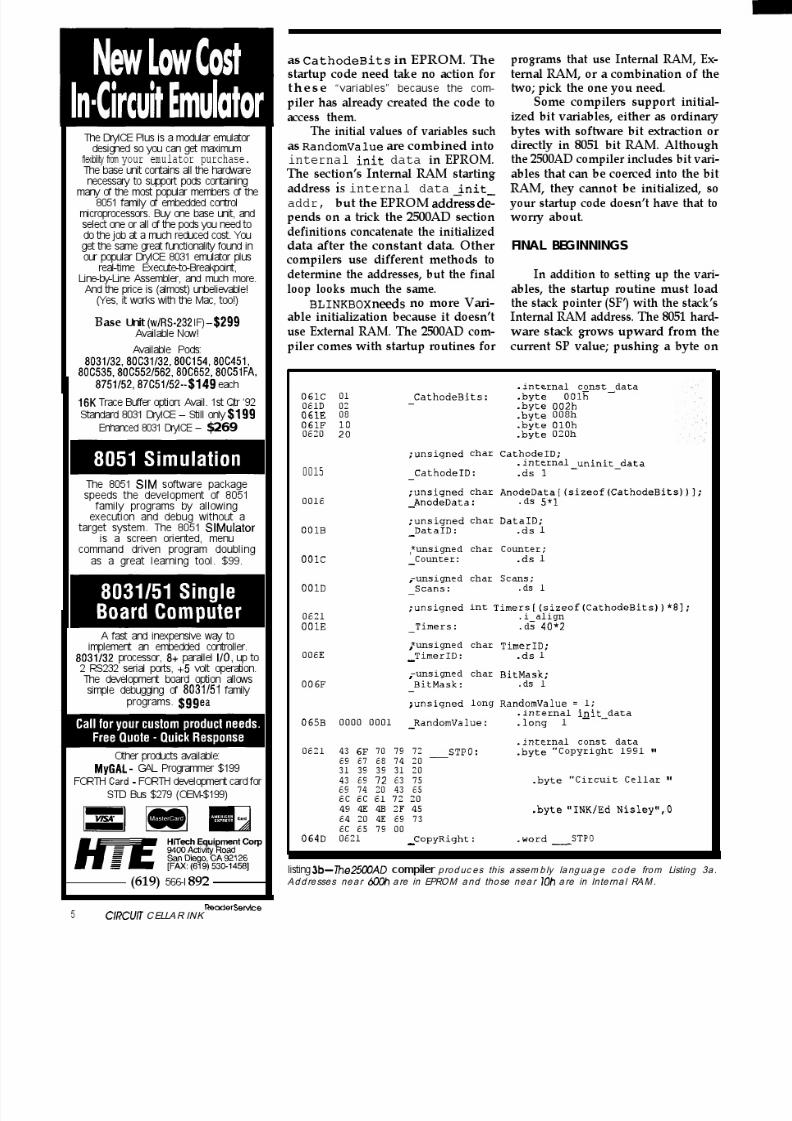
8/13/2019 Circuit.cellar.023.Oct Nov.1991
http://slidepdf.com/reader/full/circuitcellar023oct-nov1991 71/100

8/13/2019 Circuit.cellar.023.Oct Nov.1991
http://slidepdf.com/reader/full/circuitcellar023oct-nov1991 72/100

8/13/2019 Circuit.cellar.023.Oct Nov.1991
http://slidepdf.com/reader/full/circuitcellar023oct-nov1991 73/100

8/13/2019 Circuit.cellar.023.Oct Nov.1991
http://slidepdf.com/reader/full/circuitcellar023oct-nov1991 74/100
RedefiningRemote ControlNow You See ‘em--Beep-Now You Don’t
FROMTHE
BENCHJeff Bac hioc hi
Thank you American Airlines. It is
great to be back in the USA. Don’t get
me wrong, it’s not that I didn’t like
Mexico. It’s just a bit difficult withoutknowing adequate Spanish. 5,” “no,”
and “gracias” won’t cut it when you
need to hold an intelligent conversa-
tion Like, “What do you mean I don’t
have the proper papers to pass cus-
toms? That’s my plane!” Believe me,
you don’t argue with a uniformed
guard brandishing a “pistola.” I felt like
a malformed part on an assembly line:
Honk! The quality control inspector
checks my specs and presses the re-
ject button. Into the pile of discarded
parts I fall, along with the other bodies
who can’t speak Spanish. I’ll never say
another bad word about airlinecounter personnel, the last refuge for
a “gringo.”
Mexico is a strange combination of high and lowtechnology. Road repair is done with pickaxes, shovels,and wheelbarrows; no heavy equipment. Businessmen,however, wouldn’t be caught dead without their hand-held cellular phones. It became obvious by the number of“boops” and ‘beeps” heard during lunch (from 2 PM to 5
PM) that this was when most deals were formulated. Dealslike this one; the one which brought me to Mexico.
I IHANDS ACROSS THE BORDER
Beinghiredasaconsultant isalot likeplayingfireman.One has to know which type of extinguisher will put outthe blaze in the shortest period of time, with the leastamount of damage. If the fire has not grown too large, you
can salvage enough to create success out of failure. Thetask at hand was not a three-alarm fire, but red tapepromised to stoke the blaze.
The biggest failure of this project was a lack of firmspecifications. The product had to be continually modi-fied, because the rules changed depending on where theequipment wasbeingused. Hand-wired prototypes wouldnot work consistently in the field. This meant deliveryschedules were now approaching impossible.
I want to see specifications before I start any project.Without rules, no one can play the game fairly. Designingdata acquisition or any other type of equipment is impos-
sible without complete requirements, I’m not suggestingthis product had been designed without any specifica-tions. I’m indicating that these were ideal specificationsand only realistic in an ideal environment. The actualenvironment can play havoc with what you might expectto see. Environmental noise, from subaudio through RF,can have an impact on your data. In most cases, simply bylooking at the data in the actual environment, you candetermine if the environment is adding anything to theraw signal. If it is, you can make appropriate changes in thespecifications to eliminate it. It is important that you andyour customer agree to the specifications prior to any
agreement or, like this company, you may never get out ofthe design stage.
LET’S SIMPLIFY THINGS
Simplifying a client’s design can often result in majorcost saving, especially when production quantities arehigh, and establishes the true value of hiring a consultant.For instance, this client’s product used a aptop as a serialI/O device permanently attached to the product. Otherhardware could be used here to simplify the product andmake it more user friendly.
One of the most exciting products I’ve seen lately is theconfigurable legend switch (see “Silicon Update” in Issue
October/November J 99 J 79

8/13/2019 Circuit.cellar.023.Oct Nov.1991
http://slidepdf.com/reader/full/circuitcellar023oct-nov1991 75/100
PI+-. I
P16-
PlSdPM+p13-P,Z$PI,--
Pd-FOR LM2136
A NN UN CI A TO R
40KHz OSCILLATOR I 01DUIIVPi) L
Figure 1 -The complete schematic for the ha nd-held LCD terminal doe sn ‘ t inc lude muc h mo re tha n an 875 controllerplus som e sim p le interface circuits.
#20,April/May199l,ofC1~currC~~~~~INKforrnoreinfo).These are expensive little buggers, but increase flexibilityto the point of payback in many cases. This idea could beused to reduce the number of keys necessary on a product,like the one being developed in Mexico.
Every time I pick up my calculator, my mind goes intoa whirl. Every key has a legend printed on it, as well as oneabove it and one below it. Some of them are printed inwhite, while others are printed in orange, green, orblue. Ithas a shift key, a mode key, and arrow keys. It doesn’t havea help key. You might have such a calculator somewherecollecting dust because you’ve lost the manual. Unless I
used it every day, I would quickly forget the correct keysequences to do various functions. Powerful, but not userfriendly.
A better approach for I/O would be to use a simpleLCD display to provide output and redefine the functionsof a few keys. You can see this being introduced on somenewer test equipment.
HASTA LA VISTA
During the five-hour flight back to Connecticut (thanksagain, American), my mind slipped back to thoughts of
home control. I couldn’t think of a much simpler approachfor I/O on my home control system.
80 ClRCUlT C ELLAR NK
I began scratching out bits of circuitry on the back ofmy drink napkin. My initial thought was to use an RTC52with an RTC-LCD board, which has a LCD display drivenby memory mapped I/O. I realized immediately that itwould be overkill. A micro which receives ASCII serialinput and directly drives an LCD panel could scan keysand send serial ASCII with few, if any, additional chips. An8751 would serve well here. That would eliminate anaddress latch, RAM, and EPROM. With a few glue chips Icould map the LCD into I/O space. No, that’s not what Edwould do. I remembered his “Firmware Furnace” col-umns on LCDsand keyboards (see issues and 16). I felt
a bit of a challenge here-I’m not much of a software junkie. “Just to keep the glue to a minimum,” I kept sayingover and over, trying to convince myself that it was neces-sary.
PALM-SIZED TERMINAL
I’ve previously written routines for 4 x 20 and 8 x 40
LCD displays. Since the LCD will be mainly displayingmenus for my home control system, and key definitionswill take at least one line, the small display won’t beadequate. This design will use the larger display which has
a physical size of 2.5” x 8” . See Figure 1 for the completeschematic of the terminal. Only the read and write subrou-

8/13/2019 Circuit.cellar.023.Oct Nov.1991
http://slidepdf.com/reader/full/circuitcellar023oct-nov1991 76/100
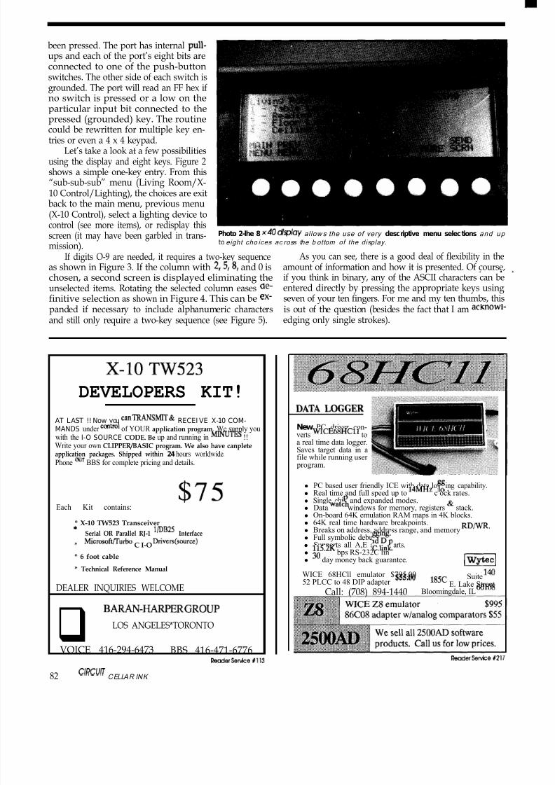
8/13/2019 Circuit.cellar.023.Oct Nov.1991
http://slidepdf.com/reader/full/circuitcellar023oct-nov1991 77/100
been pressed. The port has internal pull-ups and each of the port’s eight bits areconnected to one of the push-buttonswitches. The other side of each switch isgrounded. The port will read an FF hex ifno switch is pressed or a low on theparticular input bit connected to thepressed (grounded) key. The routine
could be rewritten for multiple key en-tries or even a 4 x 4 keypad.
Let’s take a look at a few possibilitiesusing the display and eight keys. Figure 2shows a simple one-key entry. From this“sub-sub-sub” menu (Living Room/X-10 Control/Lighting), the choices are exitback to the main menu, previous menu(X-10 Control), select a lighting device tocontrol (see more items), or redisplay thisscreen (it may have been garbled in trans-mission).
Photo 2-lhe 8 x40 dispk~y allow s the use of very descriptive menu selections and up to eight cho ices ac ross the b ottom of the display.
If digits O-9 are needed, it requires a two-key sequence As you can see, there is a good deal of flexibility in theas shown in Figure 3. If the column with 2,5,8, and 0 is amount of information and how it is presented. Of course,chosen, a second screen is displayed eliminating the if you think in binary, any of the ASCII characters can beunselected items. Rotating the selected column eases de- entered directly by pressing the appropriate keys usingfinitive selection as shown in Figure 4. This can be ex- seven of your ten fingers. For me and my ten thumbs, thispanded if necessary to include alphanumeric characters is out of the question (besides the fact that I am acknowl-and still only require a two-key sequence (see Figure 5). edging only single strokes).
X-lOTW523
DEVELOPERS KIT!
AT LAST !! Now you cm TRANSMlT RECEI VE X-10 COM-MANDS under control of YOUR application program. We supply youwith the I-O SOURCE CODE. Be up and running in MINUTES !!Write your own CLIPPER/BASIC program. We also have canpleteapplication packages. Shipped within 24 hours worldwide.Phone cur BBS for complete pricing and details.
Each Kit contains: 7 5
* X-10 TW523 Transceiver
* Serial OR Parallel RJ-1 l/DB25 Interface
* Microsofflurbo C I-O Drivers(source)
* 6 foot cable
* Technical Reference Manual
DEALER INQUIRIES WELCOME
q BARAN-HARF’ERGROUP
LOS ANGELES*TORONTO
VOICE 416-294-6473 BBS 416-471-6776
DATA LOGGER
New PC driver con-verts WICE68HCll toa real time data logger.Saves target data in afile while running user program.
l PC based user friendly ICE with data lo ing capability.l Real time and full speed up to 14MHz c ock rates.l Single chi and expanded modes.l Data watt windows for memory, registers & stack.l
On-board 64K emulation RAM maps in 4K blocks.l 64K real time hardware breakpoints.l Breaks on address, address range, and memory RDIWR.l Full symbolic debu ng.l Supports all A,E an D
Tparts.
l 115.2K bps RS-232C lin .l 30 day money back guarantee.
(WyteclWICE 68HCll emulator $795.0052 PLCC to 48 DIP adapter $55.00
Suite 14018X-T E. Lake Street
Call: (708) 894-1440 Bloomingdale, IL 60108
ReoderServi cefl 13
82 CIRCUIJ CELLAR INK
ReaderSewce+217
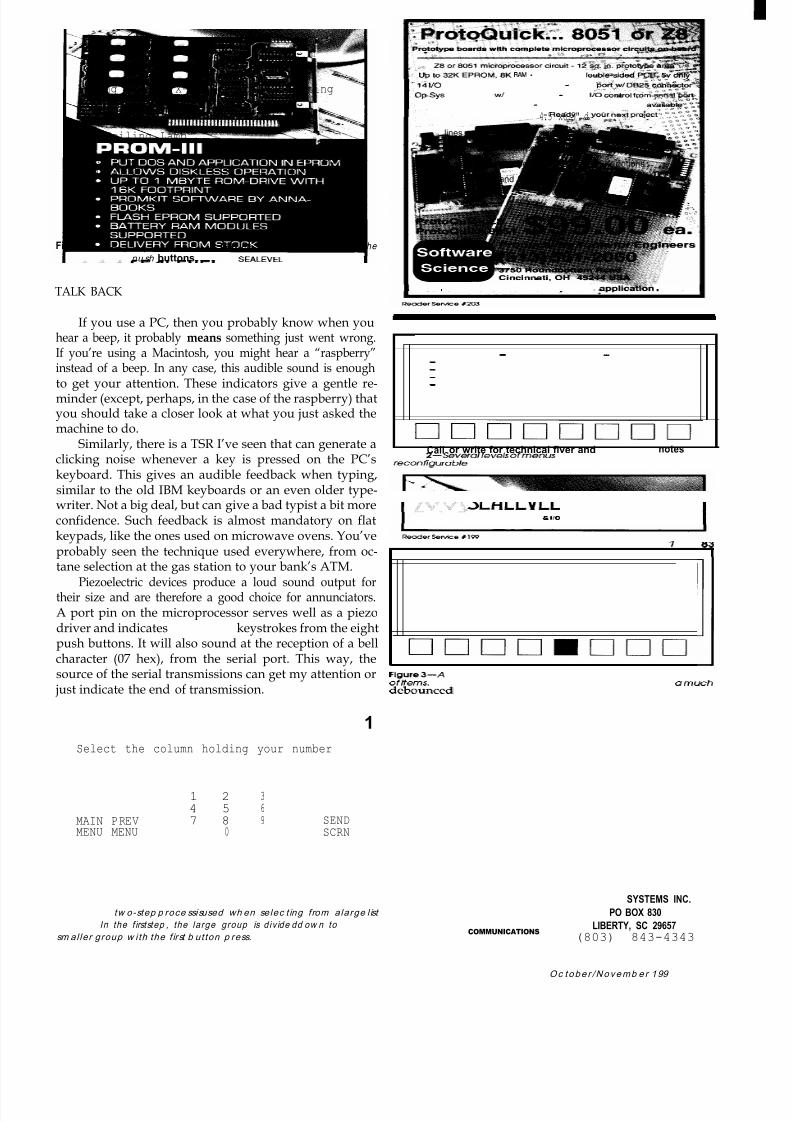
8/13/2019 Circuit.cellar.023.Oct Nov.1991
http://slidepdf.com/reader/full/circuitcellar023oct-nov1991 78/100
Living Room - X-10 Control - Lighting1 - Table Lamp2 - Reading Lamp3 - Floor Lamp4 - Ceiling Lamp
MAIN PREV SENDMENU MENU 1 2 3 4 MORE SCRN
Figure 2 Seve ra l/ eve /s ofmenus can be easi ly traversedusing the
pu sh buttons.
TALK BACK
If you use a PC, then you probably know when youhear a beep, it probably means something just went wrong.If you’re using a Macintosh, you might hear a “raspberry”
instead of a beep. In any case, this audible sound is enoughto get your attention. These indicators give a gentle re-minder (except, perhaps, in the case of the raspberry) thatyou should take a closer look at what you just asked themachine to do.
Similarly, there is a TSR I’ve seen that can generate aclicking noise whenever a key is pressed on the PC’skeyboard. This gives an audible feedback when typing,similar to the old IBM keyboards or an even older type-writer. Not a big deal, but can give a bad typist a bit moreconfidence. Such feedback is almost mandatory on flatkeypads, like the ones used on microwave ovens. You’ve
probably seen the technique used everywhere, from oc-tane selection at the gas station to your bank’s ATM.
Piezoelectric devices produce a loud sound output fortheir size and are therefore a good choice for annunciators.A port pin on the microprocessor serves well as a piezodriver and indicates debounced keystrokes from the eightpush buttons. It will also sound at the reception of a bellcharacter (07 hex), from the serial port. This way, thesource of the serial transmissions can get my attention orjust indicate the end of transmission.
Select the column holding your number
1 2 34 5 6
MAIN PREV 7 8 9 SENDMENU MENU 0 SCRN
1 igureJ-A tw o-step p roce ssisused wh en selec t ing from alarge l ist
of i tems. In the f irststep , the large group is div ide dd ow n to am u c hsm al ler group w ith the f irst b utton p ress.
RAM 4.5 x6.5" d
14 l/O lines and decoded DIP switch - Serial pWtw/ DB2$ti&%&3~k
BpSys in EPROM, w/ source code - RAM, l/O “&&rol f~& t’ ” F, d a *
Cross assembler included - CMOS and BASK: options a&@ &*,
Assembled and tested - Readv for voPf neg oroiect: ’
Call or write for technical flver and appli notes
SEALEVEL SYSTEMS INC.
PO BOX 830
COMMUNICATIONS 6 I/O LIBERTY, SC 29657(803) 843-4343
Oc tobe r /Novemb e r 199
8/13/2019 Circuit.cellar.023.Oct Nov.1991
http://slidepdf.com/reader/full/circuitcellar023oct-nov1991 79/100

8/13/2019 Circuit.cellar.023.Oct Nov.1991
http://slidepdf.com/reader/full/circuitcellar023oct-nov1991 80/100

8/13/2019 Circuit.cellar.023.Oct Nov.1991
http://slidepdf.com/reader/full/circuitcellar023oct-nov1991 81/100

8/13/2019 Circuit.cellar.023.Oct Nov.1991
http://slidepdf.com/reader/full/circuitcellar023oct-nov1991 82/100
SILICON
1 ;mraFyE Nuts About RISC
G o on a Low -Fa t Ac o rn D ie t
A lmost three years ago, in the first issue of CIRCUIT CELLAR INK, I wrote short
piece entitled “RISC vs, Reality” in which I, with tongue somewhat in cheek,
attacked the RISC hype and zealotry then at its most strident.
The main point, admittedly presented with inflammatory rhetoric, was that
RISC was more a marketing ploy than a technological “revolution. m Essentially,
the RISC concept (which I was careful to point out, has some technical merit)
had devolved to mean any new chip which isn’t an 80x86 or 68xxx.
Since then, having failed to displace low-end PCs (i.e., 80x86- and 68xxx-
based systems), many RISC suppliers are pushing (hoping) for an “embedded
RISC” market to emerge.
For some reason, whenever I hear the term embeddedRISC I can’t help but visualize a “UNIX toaster.” Built-inmultitasking means you can burn more slices at once whilethe ubiquitous Ethernet port handily connects to yourcoffee maker. Even the fussiest chef won’t tax a 4gigabytevirtual address space.
Frankly, so far most of the embedded RISC offeringsare about as practical as a UNIX toaster. However, there ishope on the horizon as suppliers migrate their existing“CRISCs” (Complex RISCs, or UNIX chips optimized forcranking floating-point loops) towards “Retro-RISCs,”
whichattempt to recapture the simplicity and innocence ofthe original concept; kind of the micro equivalent of theMazda Miata.
As suppliers continue to strip unneeded UNIX bag-gage and cut prices and chip count into the realm of real-world controller feasibility, I imagine I’ll have more to sayabout embedded RISC.
Meanwhile, we can start with one of the oldest RISCswhich, thanks to its age, turns out to be a good example ofa Retro-RISC. Whether the Acorn CPU (now rechristenedthe “ARM” for Advanced RISC Machines) itself takes offor not is hard to predict. Nevertheless, I think we can catch
a glimpse of tomorrow’s popular embedded micros intoday’s ARM.
86 C lRC UlT CELLAR INK
HIGH-FAT CHIPS
The problem with most RISCs is that there is nothingreduced about them. In the beginning, the RISC argumentwas that a simple CPU and a complex compiler couldachieve performance similar to the opposite (i.e., complexCPU, dumb compiler) setup. This is meritorious-better tospend more initially for a fancy compiler if the payback issmaller/cheaper CPUs in each and every unit sold.
Somewhere along the line, reflecting various players’marketing agendas, the RISC pitch mutated from one of
“good performance at lower price” to “highest perfor-mance at any price.” Thus, we end up with “reduced”chips like the i86OXP with 2.5 million transistors and a$500+ price tag! Unless you’re designing the mother of alltoasters, it’s not very relevant.
In the quest for performance, traditional RISC featuresare being jettisoned left and right to the degree that theterm RISC has become meaningless technically (if in doubt,revert to the marketing definition: RISC = NOT [80x86 OR68~~x1). Even the feature most identified with RISC-LOAD/STORE architecture (ALU works only on regis-ters, not memory operands)-may be under attack. In a
recent review of a new controller chip featuring LOAD/STORE, one pundit noted that “programmers won’t ap-

8/13/2019 Circuit.cellar.023.Oct Nov.1991
http://slidepdf.com/reader/full/circuitcellar023oct-nov1991 83/100
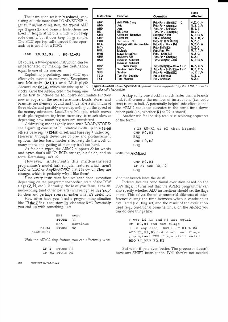
8/13/2019 Circuit.cellar.023.Oct Nov.1991
http://slidepdf.com/reader/full/circuitcellar023oct-nov1991 84/100

8/13/2019 Circuit.cellar.023.Oct Nov.1991
http://slidepdf.com/reader/full/circuitcellar023oct-nov1991 85/100
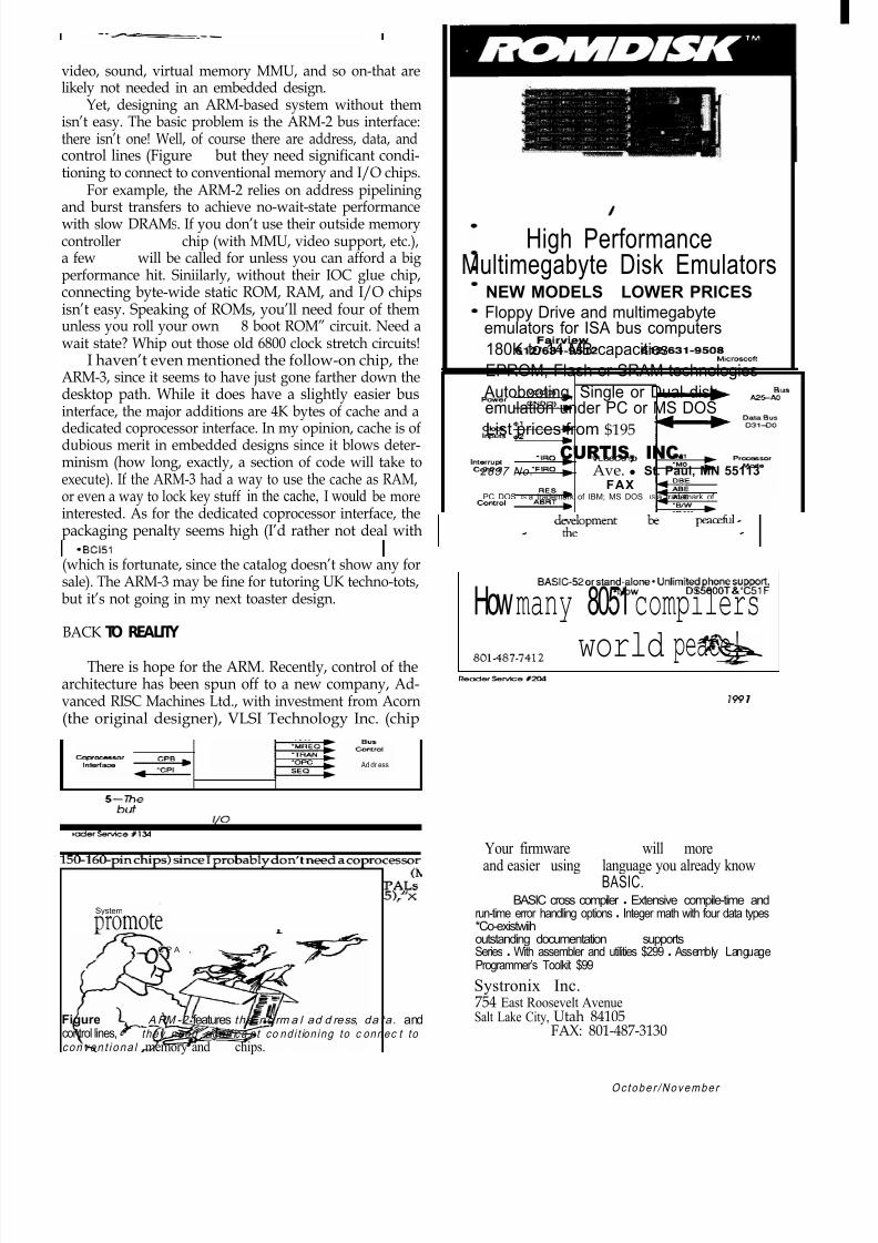
8/13/2019 Circuit.cellar.023.Oct Nov.1991
http://slidepdf.com/reader/full/circuitcellar023oct-nov1991 86/100
video, sound, virtual memory MMU, and so on-that arelikely not needed in an embedded design.
Yet, designing an ARM-based system without themisn’t easy. The basic problem is the ARM-2 bus interface:there isn’t one! Well, of course there are address, data, andcontrol lines (Figure 51, but they need significant condi-tioning to connect to conventional memory and I/O chips.
For example, the ARM-2 relies on address pipelining
and burst transfers to achieve no-wait-state performancewith slow DRAMS. If you don’t use their outside memorycontroller (MEMC) chip (with MMU, video support, etc.),a few PALS will be called for unless you can afford a bigperformance hit. Siniilarly, without their IOC glue chip,connecting byte-wide static ROM, RAM, and I/O chipsisn’t easy. Speaking of ROMs, you’ll need four of themunless you roll your own “x 8 boot ROM” circuit. Need await state? Whip out those old 6800 clock stretch circuits!
I haven’t even mentioned the follow-on chip, theARM-3, since it seems to have just gone farther down thedesktop path. While it does have a slightly easier bus
interface, the major additions are 4K bytes of cache and adedicated coprocessor interface. In my opinion, cache is ofdubious merit in embedded designs since it blows deter-minism (how long, exactly, a section of code will take toexecute). If the ARM-3 had a way to use the cache as RAM,or even a way to lock key stuff in the cache, I would be moreinterested. As for the dedicated coprocessor interface, thepackaging penalty seems high (I’d rather not deal with
(which is fortunate, since the catalog doesn’t show any forsale). The ARM-3 may be fine for tutoring UK techno-tots,but it’s not going in my next toaster design.
BACK TO REALITY
There is hope for the ARM. Recently, control of thearchitecture has been spun off to a new company, Ad-vanced RISC Machines Ltd., with investment from Acorn(the original designer), VLSI Technology Inc. (chip
POWW
CbdcInputs ::
Interrupt‘IRQ
COlltVJl ‘FIAQ
System
COtltK4
C P A ,
Ad dr ess Bus
E A0
Figure 5-The ARM -2 features the no rm a l ad d ress, da ta . andcontrol lines,but they need sign i f ica n t co nd i t ion ing to c onnec t to conven t i ona l memory and I/O chips.
High PerformanceMultimegabyte Disk Emulators
NEW MODELS / LOWER PRICESFloppy Drive and multimegabyteemulators for ISA bus computers
180K to 14 MB capacities
EPROM, Flash or SRAM technologies
Autobooting, Single or Dual disk
emulation under PC or MS DOSList prices from $195
CURTIS, INC.2837 No. Fairview Ave. l St. Paul, MN 55113
6121631-9512 FAX 6121631-9508PC DOS IS a trademark of IBM; MS DOS IS a trademark of M~croscoft
Howmany 8051compilersPromo world peace!
Your firmware dArelopment will be more peaceti -and easier - using e language you already know -
BASIC.0 BCl51 BASIC cross compiler l Extensive compile-time andrun-time error handling options l Integer math with four data types*Co-existwiih BASIC-52orstand-alone*Unlimitedphonesupport,outstanding documentation *Now supports DS5000T & ‘C51FSeries l With assembler and utilities $299 l Assembly LanguageProgrammer’s Toolkit $99
Systronix Inc.754 East Roosevelt Avenue
Salt Lake City, Utah 84105801387-7412 FAX: 801-487-3130
Oc tobe r /Novembe r 199 1

8/13/2019 Circuit.cellar.023.Oct Nov.1991
http://slidepdf.com/reader/full/circuitcellar023oct-nov1991 87/100
8/13/2019 Circuit.cellar.023.Oct Nov.1991
http://slidepdf.com/reader/full/circuitcellar023oct-nov1991 88/100
foundry), and Apple. The involvement of Apple has in-spired speculation; my guess is the ARM core might endup buried in support chips designed for tomorrow’s Mats.
Meanwhile, ARM Inc. also supplies the usual varietyof tools running on the usual platforms: C compiler, simu-lator, assembler, linker,even (shudder) a UNIX port. WhileI don’t have specific quality info, the fact that the tools havebeen around a long time is a positive sign.
Anyway, the key point is that the new company is notconstrained to serve only one customer (Acorn/BBC) ormarket (educational PCs). Now, they have the freedom todesign chips that truly serve the embedded control mar-ket. Manufacturing is expected to open up as well sinceARM Inc. intends to license a variety of suppliers to offerstandard and custom variants based on the CPU core.
It wouldn’t be hard to make a highly integrated ver-sion of an ARM microprocessor. This would involve add-ing the modern bus interface features (chip selects, waitstates, DRAM refresh and high-speed access modes, etc.1and typical I/O functions (some timers and a UART or
two) found on contemporary competitors. The chip couldbe further enhanced (“tarted up” as they might say in the
jolly old U.K.) with a fancy interrupt controller, low-poweroperation modes, and similar bells and whistles. A la “MyFair Lady,” the once homely ARM can be transformed.
Even better, why not take advantage of the CPU’s tinysize to pack on a lot of (EP)ROM and RAM-say 64KB and4KB respectively. Since the on-chip memory could be
accessed much faster than external memory, performancewould be high and scale linearly with clock rate. With allmemory on-board, bus interface headaches disappear andlow-cost, low pin-count packages are feasible.
Thanks to its excellent efficiency (performance pertransistor), the ARM architecture is arguably one of thebest candidates to serve as the core of tomorrow’s 32-bit“C’ingle Chips. +
COMTACT
Advanced RISC Machines Ltd.Park EndSwaffhan B&beckCambridge 685 ONAEnglandPhone: 0223 813000Fax: 0223 812800
Tom Cantrell holdsa B.S. in economicsandan M.B.A.from UCLA. Heowns and operated Microfuture, Inc. and has been in Silicon Valley forten years working on chip, board, and system design and marketing.
IRS425 Very Useful426 Moderately Useful427 Not Useful
Model 250 for Algorithm Development,
Data Acquisition, Instrumentation. Audio.
l TMS32OC 25 DSP at 10 MIPS.
l Up to 192 Kwords RAM.
l Multi-Channel Analog IO - 250K Samples/set.
l Development Software, including Assembler &
Debugger.
l Applicattons Software includes FFT. Signal
Display, Data Ac quisition &Waveform Editor.
l No Gap Sampling to/from Disk at Very HighRates.
l Supports Multiboard & Standalone (EPROM)Operation.
l From $1095. Other DSP Products Available.
D ALANCO SPY89Westland Avenue
Rochester, N.Y. 14618(716) 473-3610
P-C-B ARTWORK MADE EASYCreate and Revise PCB’s in a Flash
* HERC, CGA, EGA, VGA, SUPER-VGA* HELP SCREENS* EXTREMELY USER FRIENDLY*AUTO GROUND PLANES* DOT- MATRIX, LASER and PLOTTER ART* GERBER and EXCELLON OUTPUT* CREATE YOUR OWN FILMS with 1XART
* LIBRARIES* DOWNLOAD DEMOS from 24hr. BBS!
REQUIREMENTS: IBM PC or Compatible, 384K RAMDOS 3.0or later. IBM compatible printers, HP Laser
PCBoards - layout program 99.00(PCBoards HP or HI PEN PLOlTER DRIVER 49.00)
PCROute - auto-router 99.00SuperCAD - schematic pgm. 99.00Demo Pkg. - ( includes all 3 programs) 10.00
Call or write for more information
PCBoards2110 14th Ave. South, Birmingham, AL 35205
l -800-473-PCBS/ (205)933-l 122BBS / FAX (205) 933-2954
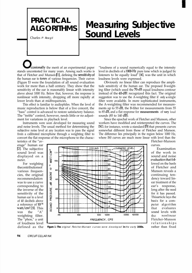
8/13/2019 Circuit.cellar.023.Oct Nov.1991
http://slidepdf.com/reader/full/circuitcellar023oct-nov1991 89/100
I
PRACTICALALGORITHMS Measuring SubjectiveCharles P. Boe g li
Sound Levels
uccasionally the merit of an experimental paperstands uncontested for many years. Among such works isthat of Fletcher and Munson [l], defining the sensitivity of
the human ear to tones of various frequencies. Their curves(Figure 1) were the foundation of all sound evaluationwork for more than a half century. They show that the
sensitivity of the ear is reasonably linear with intensityabove about 1000 Hz. Below that, however, the response isnonlinear with intensity, dropping off more rapidly atlower levels than at midfrequencies.
This effect is familiar to audiophiles. When the level ofmusic reproduction is below that of a live concert, the“bass” control is advanced to restore satisfactory balance.The “treble” control, however, needs little or no adjust-ment for variations in playback level.
Instruments were soon developed for measuring soundand noise levels. The usual method for determining thesubjective noise level at any location was to pass the signal
from a calibrated microphone through a weighting filter toconvert the flat response of the microphone to the charac-teristics of the “av-erage” human ear[21. The subjective h
sound level was 1 2 0
displayed on ameter. 100
For weightingthecontributionsofvarious frequen-cies, the original
recommendationwas to use a curvecorresponding tothe inverse of thesensitivity of thehuman ear to a levelof 40 decibels abovea reference of lo-l6watt/cm2 [3]. Thiswas the “A”weighting filter.The “phon,” a unit
of loudness leveldefined as the
“loudness of a sound numerically equal to the intensitylevel in decibels of a lOCO-Hz pure tone which is judged bylisteners to be equally loud” [4], was the unit in whichloudness levels were expressed.
Obviously no linear filter can reproduce the ampli-tude sensitivity of the human ear. The proposed B-weight-
ing filter (which used the 70-dB equal loudness contourinstead of the 40-dB) recognized this fact. The originalsuggestion was to use the A-weighting filter if only a singlefilter were available. In more sophisticated instruments,the A-weighting filter was recommended for measure-ments up to 55 dB, the B-filter for measurements from 55to 85 dB, and a flat response for measurements of very loudsounds (85 to 140 dB).
Since the epochal work of Fletcher and Munson, otherworkers have modified and reinterpreted the curves. TheISO, for instance, wrote a standard 151 that presents curvessomewhat different from those of Fletcher and Munson.
The difference lies principally in the region below 1000 Hz,where IS0 curves are much more linear with level than theFletcher-Munsoncurves.
Examinationof the work insound and noiseevaluationthatfol-lowed on the heelsof Fletcher andMunson reveals acontinuing ten-
dency toward lin-ear treatment of theear’s response,long after the needfor it has passed.
I Thisarticle lays the basis for a com- pu ter algo ri thmthat evaluatessound levels withthe nonlinear Fletcher-Munsonr e l a t i o n s h i p srather than fixedFigure 1 -The or ig inal Fletc her-Mun son c urves we re d eve lop ed in the e a rly 1930s.
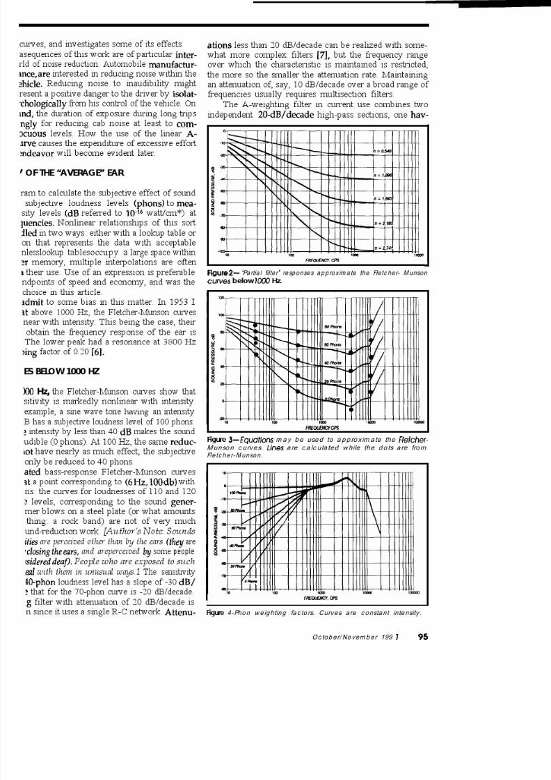
8/13/2019 Circuit.cellar.023.Oct Nov.1991
http://slidepdf.com/reader/full/circuitcellar023oct-nov1991 90/100

8/13/2019 Circuit.cellar.023.Oct Nov.1991
http://slidepdf.com/reader/full/circuitcellar023oct-nov1991 91/100

8/13/2019 Circuit.cellar.023.Oct Nov.1991
http://slidepdf.com/reader/full/circuitcellar023oct-nov1991 92/100

8/13/2019 Circuit.cellar.023.Oct Nov.1991
http://slidepdf.com/reader/full/circuitcellar023oct-nov1991 93/100

8/13/2019 Circuit.cellar.023.Oct Nov.1991
http://slidepdf.com/reader/full/circuitcellar023oct-nov1991 94/100

8/13/2019 Circuit.cellar.023.Oct Nov.1991
http://slidepdf.com/reader/full/circuitcellar023oct-nov1991 95/100

8/13/2019 Circuit.cellar.023.Oct Nov.1991
http://slidepdf.com/reader/full/circuitcellar023oct-nov1991 96/100

8/13/2019 Circuit.cellar.023.Oct Nov.1991
http://slidepdf.com/reader/full/circuitcellar023oct-nov1991 97/100

8/13/2019 Circuit.cellar.023.Oct Nov.1991
http://slidepdf.com/reader/full/circuitcellar023oct-nov1991 98/100

8/13/2019 Circuit.cellar.023.Oct Nov.1991
http://slidepdf.com/reader/full/circuitcellar023oct-nov1991 99/100
rom: RICHARD KIMBALL To: STEVE CIARCIAabout 150 feet of cable. Any feedback on this would be appreci-ated.
How about current consumption, Steve? I’m trying to put some-hing together to function in the bush over a several-month Msg :25975eriod. I’d considered the 8031/52 route, but the specter of From: KEN DAVIDSON To: PHIL ROBERTSattery depletion prevented any serious evaluation.
The R5422 spec states that you should be able to go up to 4000
feet using 24-gauge wire at data rates under 100 kbps. Your 150
rom: STEVE CIARCIA To: RICHARD KIMBALL feet shouldn’t present any problems (that’s the reason why we’ve been supporting RS-422/485 on all our new processor boards).
Remember, the 8OC52-BASIC chip is CMOS. If you remove the5176 (RS485 driver) chip, the RTC typically pulls about 15-20
. If you reduce the need for RS-232 communication and canemove the MAX232, it drops to about 8-10 mA. Then, if youeduce the crystal frequency, it starts dropping dramatically. Ictually got one board down to 2 mA while still running a BASICrogram.
rom: RICHARD KIMBALL To: STEVE CIARCIA
Hey, that ain’t so bad! I’m counting my pennies and thinkingbout how I can short change my six-year-old this Christmas.hanks again.
The Circuit Cellar BBS runs on a IO-MHz MicromintOEM-286 IBM PC/AT-compatible computer using themultiline version of The Bread Board System (TBBS2.1M) and currently has four modems connected. Weinvite you to call and exchange ideas with other CircuitCellar readers. It is available 24 hours a day and can bereached at (203) 871-l 988. Set your modem f or8 data bits,
stop bit, and either 300,1200, or 2400 bps.
IRS431 Very Useful432 Moderately Useful433 Not Useful
One of the biggest advantages of RS422 is its long-istance capability using simple twisted pair wiring, as weee here.
rom: PHIL ROBERTS To: ALL USERS
Can somebody advise on the spec for cable lengths using RS-485r RS-422. I have an application which involves mounting a piecef RF hardware as close to its antenna as possible. The unit isresently using a BCC52 to format its nonstandard output to RS32and feed a computer. I’m looking at needing to drive through
SOFTWARE and BBS AVAILABLE on DISK
Software on DiskSoftware for the articles in this issue of Circuit Cellar INK may be downloaded freeof charge from the Circuit Cellar BBS For those unable to download files, they arealso available on one 36OK, 5.25” IBM PC-format disk for only $12.
Circuil Cellar BBS on DiskEvery month, hundreds of information-filled messages are posted on the CircuitCellar BBS by people from all walks of life. For those who can’t log on as often asthey’d like, the text of the public message areas is available on disk in two-monthinstallments. Each installment comes on three 360K, 5.25” IBM PC-format disksand costs just $15. The installment for this issue of INK (OctoberNovember 1991)includes all public messages posted during July and August, 1991,
ToordereitherSoftwareonDiskorCircuitCellar BBSon Disk,sendcheckormoneyorder to:
Circuit Cellar INK Software (or BBS) on DiskP.O. Box 772, Vernon , CT 06066
pr use yourMasterCard or Visa and call (203) 875-2199. Be sure to specify the
Issue number of each disk you order. Please add $3 for shipping outside the U.S. I I
$95 EPROMPROGRAMMER
PLU S INTOPRINTERPORT00 ROMS FORBC m MVOSK PROGR M 2764 270 0 EPROMS
Recderset i e 170
October/November 199 1 105

8/13/2019 Circuit.cellar.023.Oct Nov.1991
http://slidepdf.com/reader/full/circuitcellar023oct-nov1991 100/100
STEVE’SOWNINK
1Steve Ciarcla
The Circuit (Storm) Cellar
1 here’s a funny thing about New Englanders and Hurri-
canes. For most of the year we sit around fearing that the next
hurricane will blow us off the face of the earth, yet at the same
time we are thoroughly disappointed when a hurricane happens
to choose someone else as the target of opportunity. After all,
why go through all the preparations and not have the satisfaction
of a good story to tell afterwards.
All New Englanders haveanindigenous yearning to survive
through a particularly devastating hurricane and then narrate,
with particular exaggeration, all the details to future generations
of friends and relatives. “Boy, you should have been around back
in 1954. We had Carol on August 31, Edna on September 11, and
then Hazel on October 15 It took six months to dry out, and was
the worst...”
Right now I’m sitting in the Circuit Cellar waiting for Hur-
ricane Bob to zero in on me. I’m using a UPSbacked computer so
I don‘t have to rewrite this whole thing after the crash. Even with
the rather regular power glitches starting to occur, I’ve still got
one TV on a local station and another on the cable Weather
Channel. According to the latest reports, Bob’s headed straight
for the Rhode Island/Connecticut border. Unfortunately, my
house is 40 miles from Rhode Island on a hill surrounded by
potentially brittle trees.
Actually, I’m probably more prepared than most people to
make it through natural disasters, but I equivocate over terminol-
ogy like “survivalist” in any descriptions. I’ve already checked
the propane-powered backup generator. It’s one of those big
two-cylinder jobs that’s supposed to do the whole house. Given
all the electrical goodies around here, however, I have to shed
Let’s see, I’ve pulled out some extra tarps: three 5’ x 7, two
9’x12’,a17’x29’,anda27’x39’.I’vechargedthreeextra12-V100-
AH batteries for the pump, eight 12-V 6.5AH batteries for the
radios and TVs, and made sure the Circuit Cellar automatic low-
voltage lighting system is ready. There are the rechargeable
flashlights (7), the regular flashlights (6) and a box of two dozen
D-cells, the car cigarette-lighter-type fluorescent lights (31, and
two 12-V portable power packs (just in case). After all, there’s a
hurricane coming.. .
Let’s see, the AM/FM radio and a shortwave unit are ready
but, wait, what about a TV? The two sets operating behind me are115-V units. I don’t want to have to start the generator to use
them. Better go do an inventory of battery-operated stuff.
I guess I must never throw anything out. I was amazed at
what was on the shelves of the Circuit Cellar. There were nine
battery-operated TV sets, ranging from 1”-6” B&W and color
conventional TVs to the latest 3” and 4” color LCD units. Unfor-
tunately, no one ever discussed hurricanes with the designers or
each wouldn’t have had such varied operating voltages and
unique connector configurations. The lowest-power LCD units
had the weirdest connectors and operated at voltages like 9.8 V
or 10 V. The largest conventional color TV had a readily available
connector and ran on 12 V but would have consumed a whole
battery between commercials.
Here was the first obstacle and the storm was only an hour
away. Warm up the soldering iron, quick. Do I settle on a 1” 6-V
Panasonic unit and get a magnifying glass; whip up a quick 12-
V LM317-based adjustable regulator with assorted universal
output connectors and polarity reversers; swipe one of the ma-


![DTIC QUALIT ^JtjJJLiUJi, China · 2020. 2. 20. · JPRS-CAR-91-023 25 APRIL 1991 JPRS Report— DTIC QUALIT --v „ ^JtjJJLiUJi, China QIUSHI [SEEKING TRUTH] No 4, 16 February 1991](https://img.dokumen.tips/doc/110x75/60e0f73fa6c0b8164212769b/dtic-qualit-jtjjjliuji-china-2020-2-20-jprs-car-91-023-25-april-1991-jprs.jpg)