Embed Size (px)
Citation preview
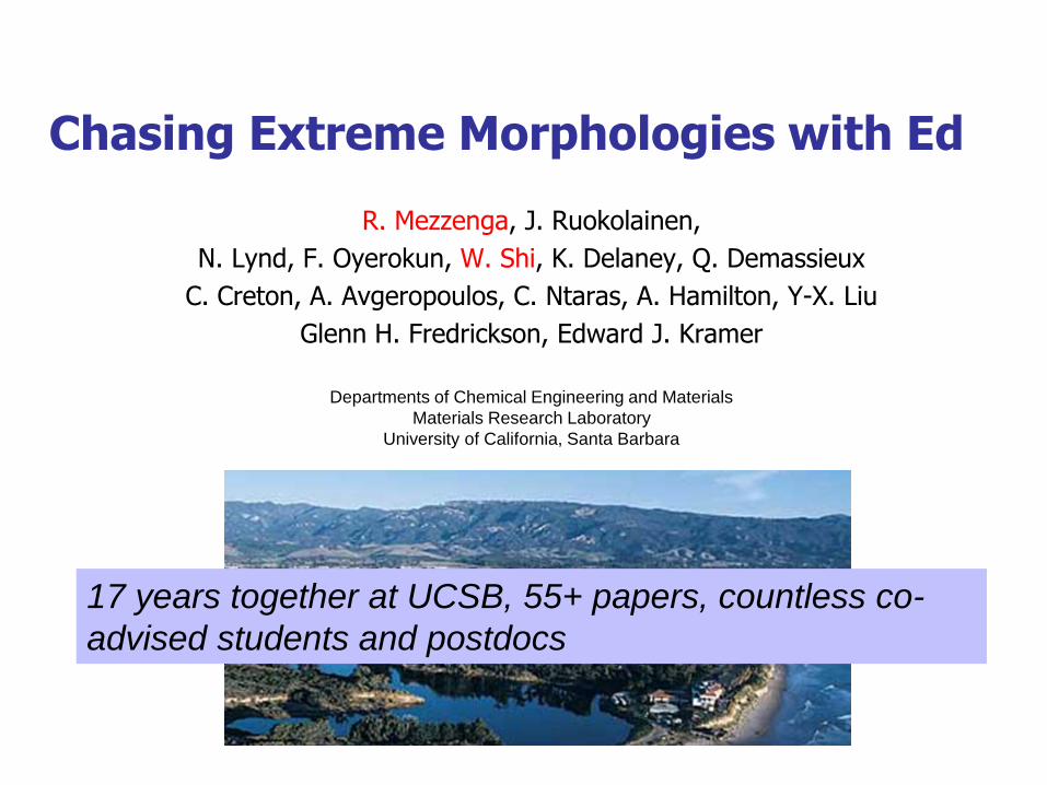
Chasing Extreme Morphologies with Ed
R. Mezzenga, J. Ruokolainen,
N. Lynd, F. Oyerokun, W. Shi, K. Delaney, Q. Demassieux
C. Creton, A. Avgeropoulos, C. Ntaras, A. Hamilton, Y-X. Liu
Glenn H. Fredrickson, Edward J. Kramer
Departments of Chemical Engineering and Materials
Materials Research Laboratory
University of California, Santa Barbara
17 years together at UCSB, 55+ papers, countless co-
advised students and postdocs

Outline
High internal phase polymeric emulsions (2002-2004)
Micron scales, non-equilibrium structures
Miktoarm copolymer alloys (2007-present)
Nanometer scales, equilibrium structures
In both cases, we were focused on achieving unusual
cellular morphologies with a discrete phase present up to
very high volume fractions
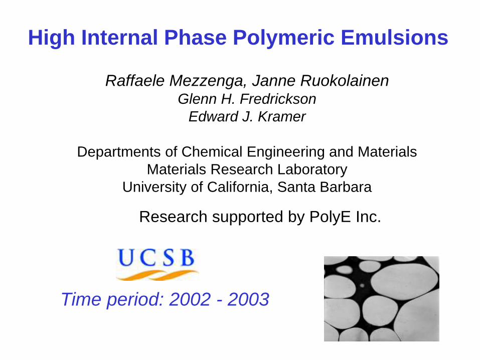
High Internal Phase Polymeric Emulsions
Raffaele Mezzenga, Janne Ruokolainen Glenn H. Fredrickson
Edward J. Kramer
Departments of Chemical Engineering and Materials
Materials Research Laboratory
University of California, Santa Barbara
Research supported by PolyE Inc.
Time period: 2002 - 2003
4
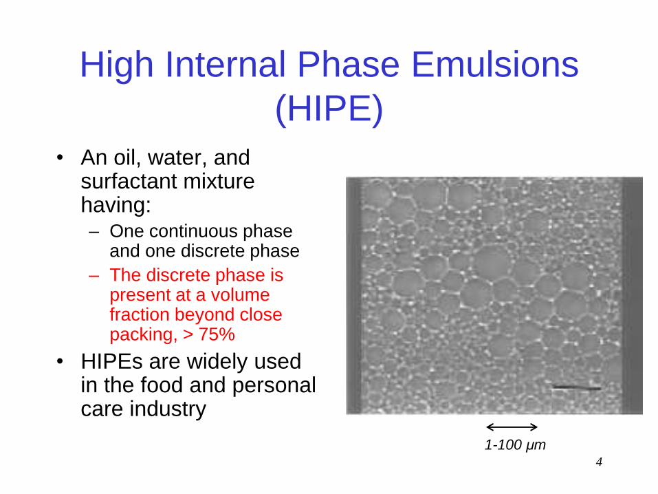
High Internal Phase Emulsions
(HIPE)
• An oil, water, and surfactant mixture having: – One continuous phase
and one discrete phase
– The discrete phase is present at a volume fraction beyond close packing, > 75%
• HIPEs are widely used in the food and personal care industry
1-100 μm
5
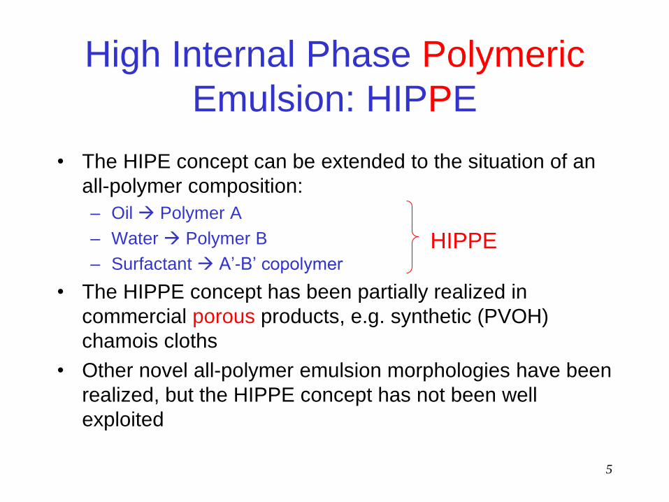
High Internal Phase Polymeric
Emulsion: HIPPE
• The HIPE concept can be extended to the situation of an
all-polymer composition:
– Oil Polymer A
– Water Polymer B
– Surfactant A’-B’ copolymer
• The HIPPE concept has been partially realized in
commercial porous products, e.g. synthetic (PVOH)
chamois cloths
• Other novel all-polymer emulsion morphologies have been
realized, but the HIPPE concept has not been well
exploited
HIPPE

6
Potential Applications of HIPPE
Structures
• Continuous minor phase creates opportunities for exceptional and controlled transport properties at low cost: – Ion or electron-conducting films or membranes
– Films with barrier properties or chemical resistance
– Membranes with unusual dielectric properties, e.g. polymer electrets
– Controlled release materials and structures: medical and agricultural applications

7
Strategies for Producing HIPPE
Compositions
• Selective solvent casting of A + B + A’B’
• Selective solvent casting of particle-A + A’B’ + B
• Selective solvent casting of particle-A + A’B’
• Melt processing of A + B + A’B’ (Never realized)
8
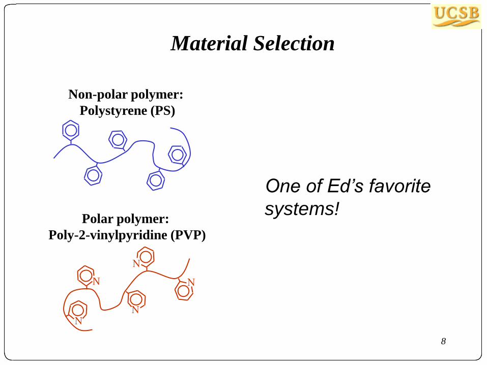
Material Selection
Non-polar polymer:
Polystyrene (PS)
N
Polar polymer:
Poly-2-vinylpyridine (PVP)
One of Ed’s favorite
systems!

9
Non-equilibrium solvent preparation:
-PolyHIPE via emulsification-
Materials Procedures
(A continuous/B discrete)
Polymers
Solvents
• Polystyrene (PS) • Poly2vinylpyridine (PVP)
PS-PVP block copolymers
• PS-PVP1, fPVP=0.84
• PS-PVP2, fPVP=0.13
Common solvent for PS and PVP: Chloroform
Good solvents for PS: Toluene, Cyclohexane
Good solvent for PVP: Ethanol
+ + solvent A A 1)
+ solvent B B 2)
A
3)
10
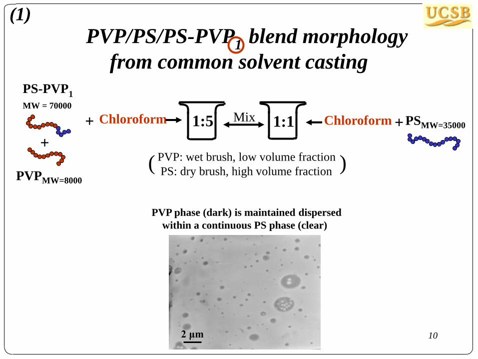
PVP/PS/PS-PVP1 blend morphology
from common solvent casting
+
+ Chloroform + 1:5 1:1 Chloroform
PS-PVP1
MW = 70000
PVPMW=8000
PSMW=35000
PVP: wet brush, low volume fraction
PS: dry brush, high volume fraction ( )
Mix
2 μm
PVP phase (dark) is maintained dispersed
within a continuous PS phase (clear)
(1)

11
+
+ Ethanol + 1:5 1:1 Toluene
PS-PVP1
PVPMW=8000
PSMW=35000 Mix
Emulsification process
20 μm
Liquid emulsion Emulsion after solvent removal
1 μm
PVP/PS/PS-PVP1 blend morphology
from selective solvent casting
(2)

12
+
+ Toluene + 1:5 1:1 Ethanol
PS-PVP2
MW=114000
PSMW=9000
PVPMW=42000 Mix
NO EMULSIFICATION !
20 μm
Still liquid…. …after solvent removal
2 μm
PVP/PS/PS-PVP2 blends from
selective solvent casting
13
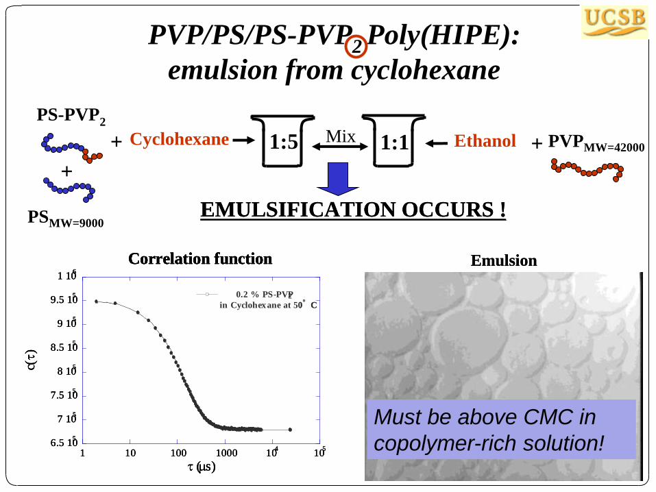
PVP/PS/PS-PVP2 Poly(HIPE):
emulsion from cyclohexane
+
+ Cyclohexane + 1:5 1:1 Ethanol
PS-PVP2
PSMW=9000
PVPMW=42000 Mix
EMULSIFICATION OCCURS !
Correlation function EmulsionCorrelation function
1 10 100 1000 104
105
6.5 105
7 105
7.5 105
8 105
8.5 105
9 105
9.5 105
1 106
0.2 % PS-PVP
in Cyclohexane at 50 C
(s)
c()
2º
EMULSIFICATION OCCURS !
Correlation function EmulsionCorrelation function
1 10 100 1000 104
105
6.5 105
7 105
7.5 105
8 105
8.5 105
9 105
9.5 105
1 106
0.2 % PS-PVP
in Cyclohexane at 50 C
(s)
c()
2º
1 10 100 1000 104
105
6.5 105
7 105
7.5 105
8 105
8.5 105
9 105
9.5 105
1 106
0.2 % PS-PVP
in Cyclohexane at 50 C
(s)
c()
2º
Must be above CMC in
copolymer-rich solution!

14
+
+
PS beads (x-linked) and PS-PVP1
are mixed in Ethanol
Precipitation
15% PS-PVP
85% PS
0.8 μm
After solvent evaporation
PS colloid-block copolymer dispersions
15
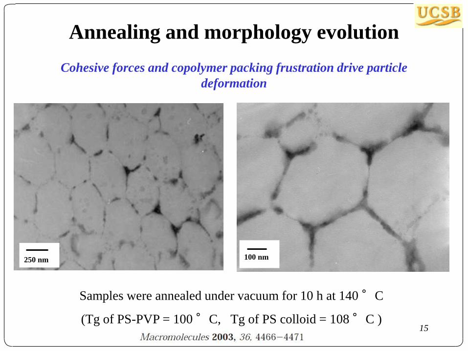
Annealing and morphology evolution
Cohesive forces and copolymer packing frustration drive particle
deformation
250 nm
Samples were annealed under vacuum for 10 h at 140 °C
(Tg of PS-PVP = 100 °C, Tg of PS colloid = 108 °C )
100 nm
16
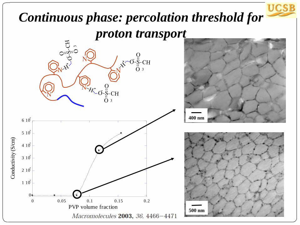
Continuous phase: percolation threshold for
proton transport
400 nm
500 nm
N
0
1 10-7
2 10-7
3 10-7
4 10-7
5 10-7
6 10-7
0 0.05 0.1 0.15 0.2
Conduct
ivit
y (
S/c
m)
PVP volume fraction
17
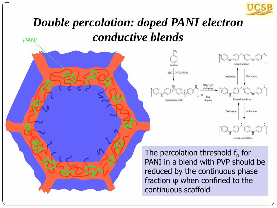
Double percolation: doped PANI electron
conductive blends
The percolation threshold fp for PANI in a blend with PVP should be reduced by the continuous phase fraction φ when confined to the continuous scaffold
PANI

18
Double percolation in PANI-PSA + PS
colloids + PS-PVP (cast from formic acid)
PANI-PSA
+ PVP
fPANI = 0.01, 0.05, 0.20
fp = 0.12
PANI-PSA
+ PS-PVP
+ PS
particle
1% PANI 3% PANI
fp = 0.01
PSA: phenol
sulfonic acid
19
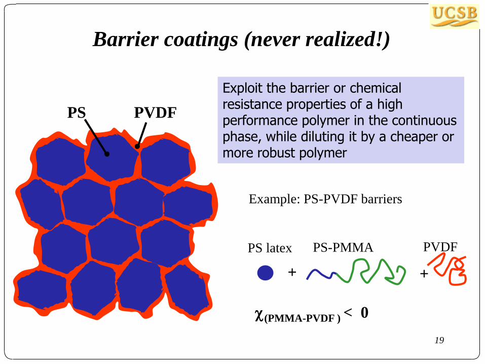
Barrier coatings (never realized!)
Exploit the barrier or chemical resistance properties of a high performance polymer in the continuous phase, while diluting it by a cheaper or more robust polymer
PS PVDF
Example: PS-PVDF barriers
PS latex PS-PMMA
+ +
PVDF
(PMMA-PVDF ) < 0
20
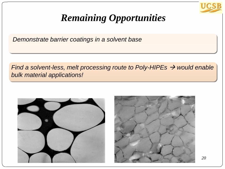
Remaining Opportunities
Demonstrate barrier coatings in a solvent base
Find a solvent-less, melt processing route to Poly-HIPEs would enable
bulk material applications!
21
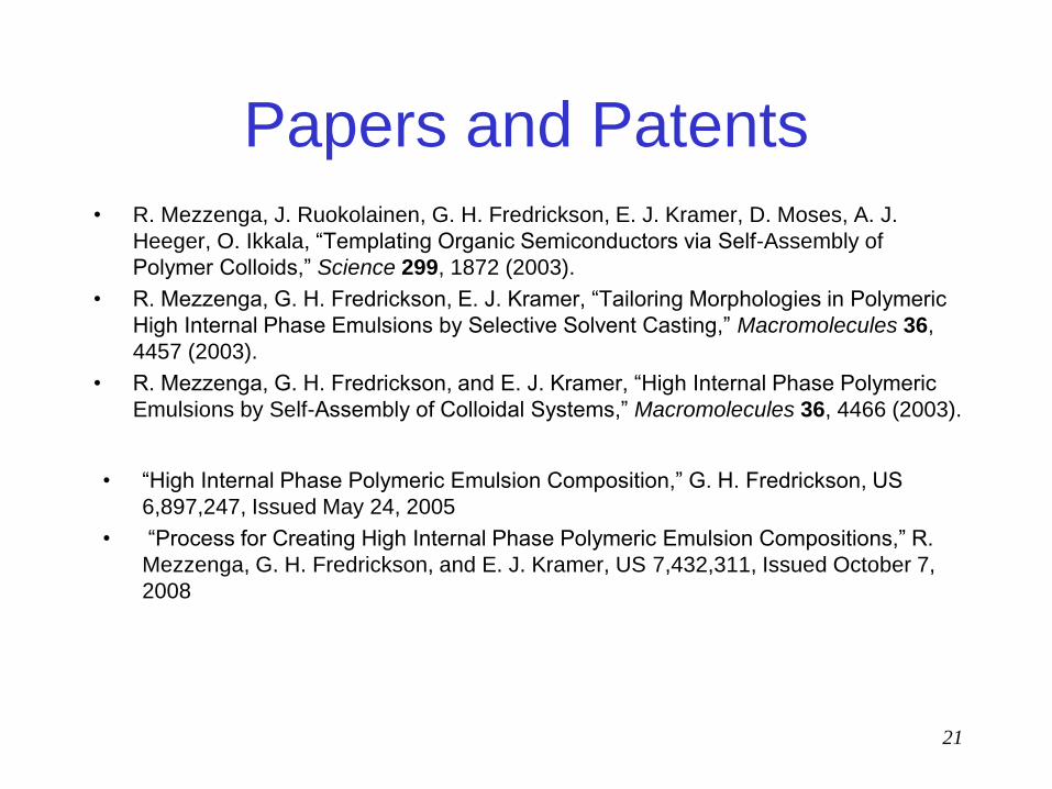
Papers and Patents • R. Mezzenga, J. Ruokolainen, G. H. Fredrickson, E. J. Kramer, D. Moses, A. J.
Heeger, O. Ikkala, “Templating Organic Semiconductors via Self-Assembly of
Polymer Colloids,” Science 299, 1872 (2003).
• R. Mezzenga, G. H. Fredrickson, E. J. Kramer, “Tailoring Morphologies in Polymeric
High Internal Phase Emulsions by Selective Solvent Casting,” Macromolecules 36,
4457 (2003).
• R. Mezzenga, G. H. Fredrickson, and E. J. Kramer, “High Internal Phase Polymeric
Emulsions by Self-Assembly of Colloidal Systems,” Macromolecules 36, 4466 (2003). • “High Internal Phase Polymeric Emulsion Composition,” G. H. Fredrickson, US
6,897,247, Issued May 24, 2005
• “Process for Creating High Internal Phase Polymeric Emulsion Compositions,” R.
Mezzenga, G. H. Fredrickson, and E. J. Kramer, US 7,432,311, Issued October 7,
2008

Miktoarm Copolymer Alloys
E. J. Kramer, F. Oyerokun, Nate Lynd, Weichao Shi,
K. Delaney, A. Hamilton, Q. Demassieux, C. Creton,
A. Avgeropoulos, C. Ntaras, Y-X. Liu, G. H. Fredrickson,
Departments of Chemical Engineering and Materials
Materials Research Laboratory
University of California, Santa Barbara
Time period: 2007 - 2016
“bricks-and-mortar” phase
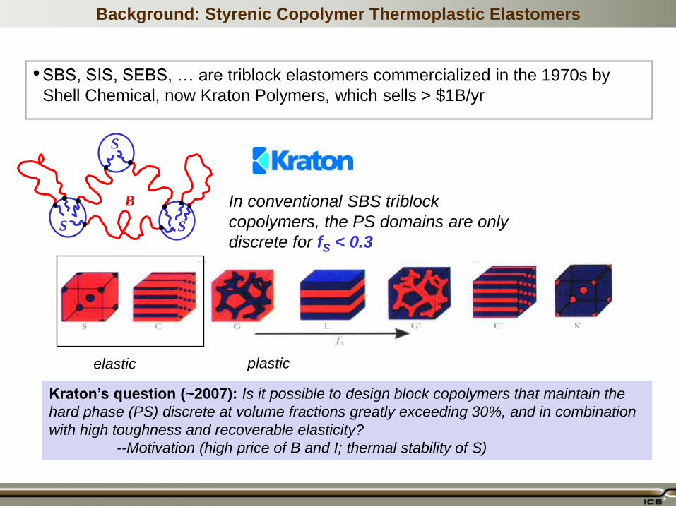
Background: Styrenic Copolymer Thermoplastic Elastomers
•SBS, SIS, SEBS, … are triblock elastomers commercialized in the 1970s by
Shell Chemical, now Kraton Polymers, which sells > $1B/yr
B
S
S S
In conventional SBS triblock
copolymers, the PS domains are only
discrete for fS < 0.3
elastic plastic
Kraton’s question (~2007): Is it possible to design block copolymers that maintain the
hard phase (PS) discrete at volume fractions greatly exceeding 30%, and in combination
with high toughness and recoverable elasticity?
--Motivation (high price of B and I; thermal stability of S)

The “Mikto-arm” Design
Our design is based on using two polymer physics principles in concert for driving interfacial
curvature towards PS: - Mikto-polymer frustration (Milner, Gido, Pochan)
- PS block polydispersity (Milner-Witten-Cates, Matsen)
•Commercially viable synthesis by
coupling living PS with living PS-PB
PS
PB
AB2 mikto-polymer Asymmetric ABA
Poor mechanical strength! Should be strong, but what are morphologies
and properties?
A concept patent and theoretical
study – properties unexplored!
D. Handlin, P. Pasman, G. H. Fredrickson,
U.S. 20,090,234,059 (2009)
N. A. Lynd et. al., Macromolecules 43, 3479 (2010)
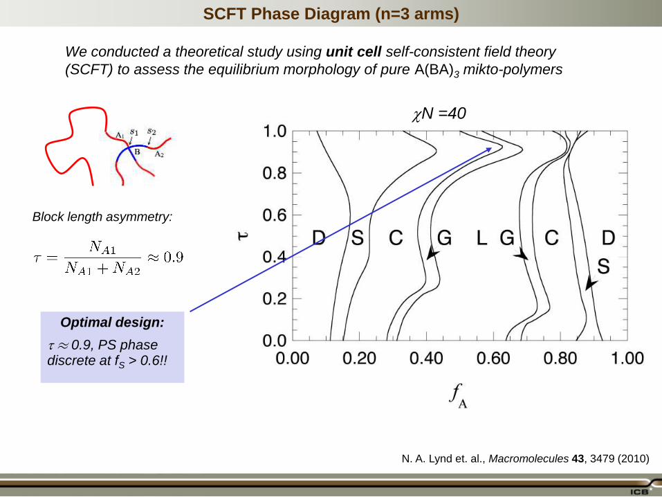
SCFT Phase Diagram (n=3 arms)
N =40
Block length asymmetry:
Optimal design:
¼ 0.9, PS phase discrete at fS > 0.6!!
We conducted a theoretical study using unit cell self-consistent field theory
(SCFT) to assess the equilibrium morphology of pure A(BA)3 mikto-polymers
N. A. Lynd et. al., Macromolecules 43, 3479 (2010)

Experimental Effort ~2011-2015
We collaborated Prof. Apostolos Averopoulos and student Cristos Nataras of the
University of Ioannina in Greece, who supplied ~100 g samples of carefully
prepared miktopolymers.
Ed Kramer joined the team and postdoc Weichao Shi led the characterization and
mechanical analysis at UCSB. Costantino Creton and student Q. Demassieux
joined subsequent to Ed’s passing.
Samples from Greece have ¿ =
0.89, n =1, 2 and 3, and PS
fractions varying from 20% to
80% in 10% increments.
All were carefully
fractionated/purified
80K PS
10K PS
PS-PI-PS Triblock:
PS-(PI-PS)3 Mikto-
polymer:
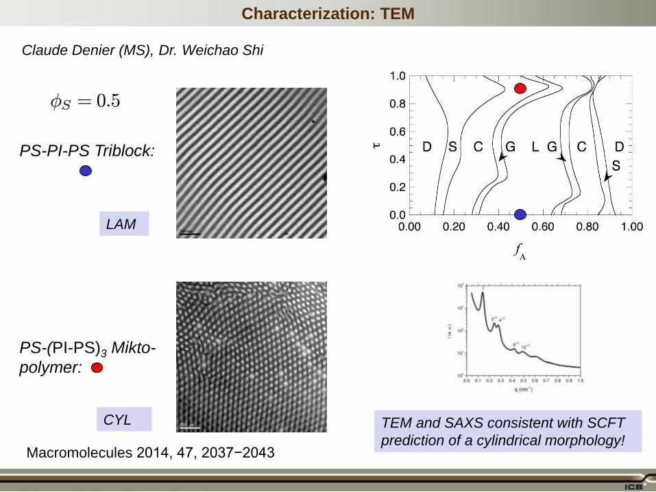
Characterization: TEM
Claude Denier (MS), Dr. Weichao Shi
ÁS = 0:5
LAM
CYL TEM and SAXS consistent with SCFT
prediction of a cylindrical morphology! Macromolecules 2014, 47, 2037−2043
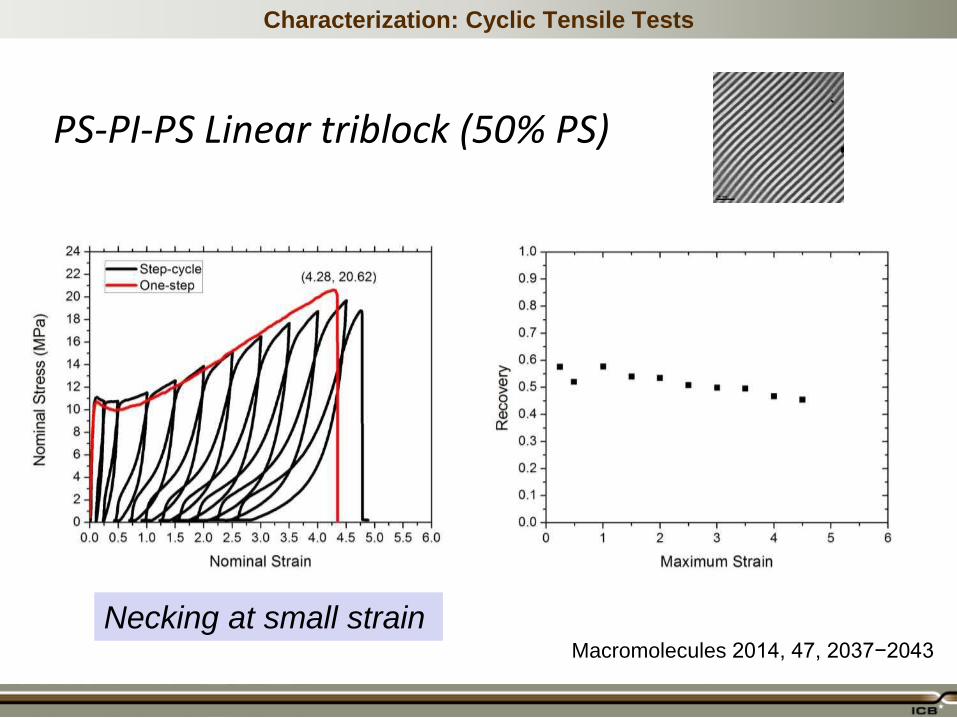
Characterization: Cyclic Tensile Tests
Necking at small strain
PS-PI-PS Linear triblock (50% PS)
Macromolecules 2014, 47, 2037−2043

Characterization: Cyclic Tensile Tests
No necking at small strain
PS-(PI-PS)3 Mikto-polymer (50% PS)
450% strain!
Macromolecules 2014, 47, 2037−2043

Higher Hard Phase Volume via Blends
Even more extreme compositions with a discrete PS phase – a nanoscale analog
to a polymeric “High Internal Phase Emulsion” – might be achievable by blending
in PS homopolymer!
Mikto-blend: • 10 nm scale • Equilibrium • Tough, elastic?
HIPPE: • 1 μm scale • Non-equilibrium • Brittle
??
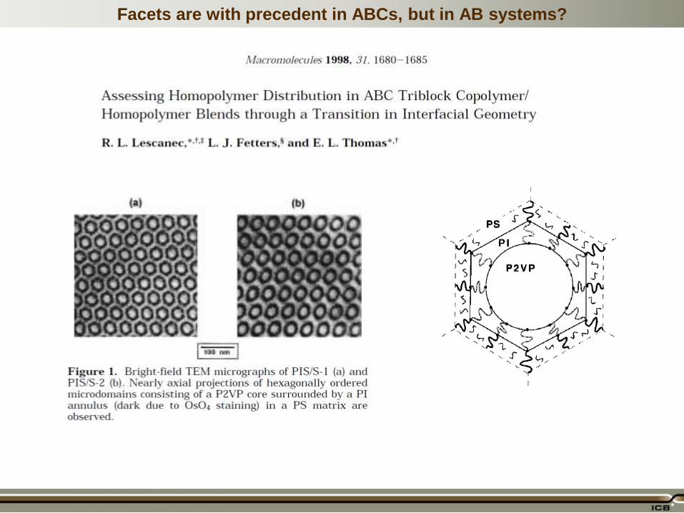
Facets are with precedent in ABCs, but in AB systems?
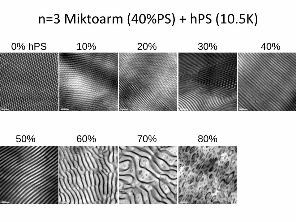
n=3 Miktoarm (40%PS) + hPS (10.5K)
0% hPS 10% 20% 30% 40%
50% 60% 70% 80%
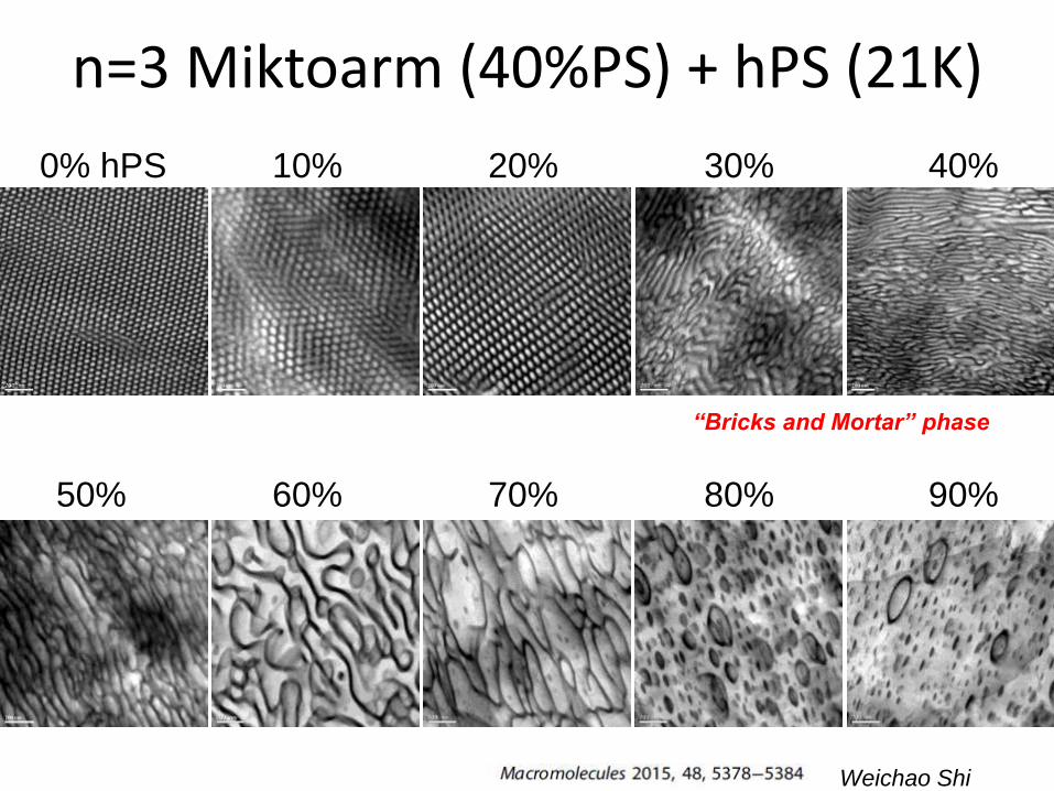
n=3 Miktoarm (40%PS) + hPS (21K)
0% hPS 10% 20% 30% 40%
50% 60% 70% 80% 90%
“Bricks and Mortar” phase
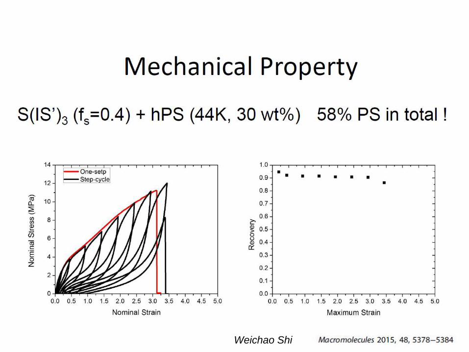
Weichao Shi
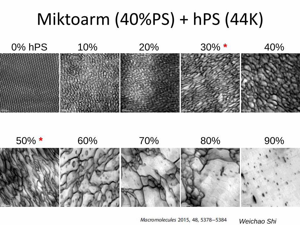
Miktoarm (40%PS) + hPS (44K)
0% hPS 10% 20% 30% * 40%
50% * 60% 70% 80% 90%
Weichao Shi
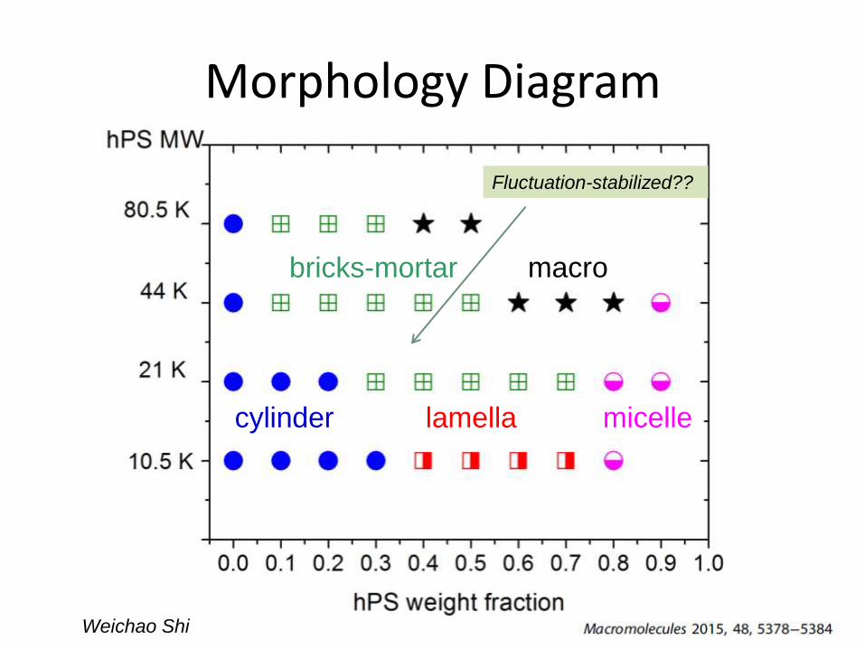
Morphology Diagram
cylinder lamella
bricks-mortar
micelle
macro
Fluctuation-stabilized??
Weichao Shi
Weichao Shi
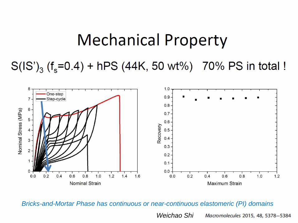
Bricks-and-Mortar Phase has continuous or near-continuous elastomeric (PI) domains
Weichao Shi
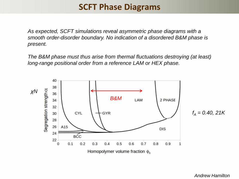
SCFT Phase Diagrams
Andrew Hamilton
As expected, SCFT simulations reveal asymmetric phase diagrams with a
smooth order-disorder boundary. No indication of a disordered B&M phase is
present.
The B&M phase must thus arise from thermal fluctuations destroying (at least)
long-range positional order from a reference LAM or HEX phase.
fA = 0.40, 21K
χN
B&M
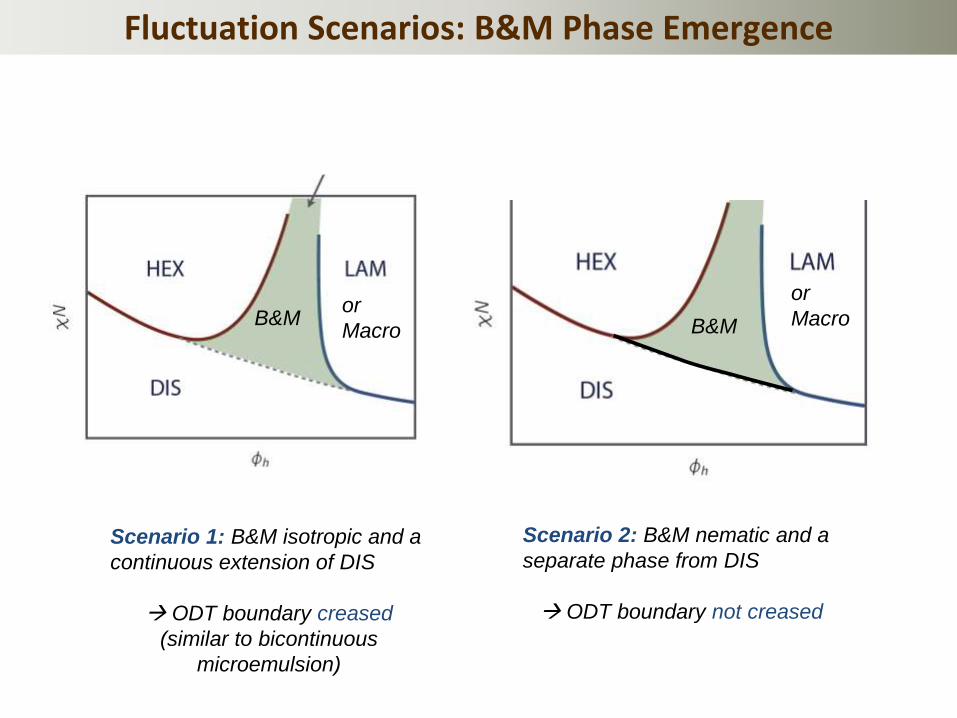
Fluctuation Scenarios: B&M Phase Emergence
Scenario 1: B&M isotropic and a
continuous extension of DIS
ODT boundary creased
(similar to bicontinuous
microemulsion)
B&M
Scenario 2: B&M nematic and a
separate phase from DIS
ODT boundary not creased
B&M or
Macro
or
Macro

Beyond SCFT—CL-FTS Simulations
C = 7, f = 0.4, ϕh = 0.5 χN = 30
χN = 28
χN = 26
χN = 25
χN = 24
LAM
B&M?
DIS
No evidence for deflected ODT Scenario 2 likely
Yi-Xin Liu, K. Delaney

Ed’s Legacy at UCSB
Michael Chabinyc
Rachel Segalman
E. N. Kramer Chair Many thanks to Rachel and Sara for their
outstanding coordination of this event!