Embed Size (px)
Citation preview

R.M. Dansereau; v.1.0
INTRO. TO COMP. ENG.CHAPTER VIII-1
FINITE STATE MACHINES
•CHAPTER VIII
CHAPTER VIII
FINITE STATE MACHINES (FSM)

R.M. Dansereau; v.1.0
INTRO. TO COMP. ENG.CHAPTER VIII-2
STATE MACHINESINTRODUCTION
FINITE STATE MACHINES
•STATE MACHINES-INTRODUCTION
• From the previous chapter we can make simple memory elements.
• Latches as well as latches with control signals
• Flip-flops
• Registers
• The goal now is to use the memory elements to hold the running state of
the machine.
• The state of the machine can be used to perform sequential operations.
• This chapter will discuss how to represent the state of the machine for
design and communication purposes.

R.M. Dansereau; v.1.0
INTRO. TO COMP. ENG.CHAPTER VIII-3
STATE MACHINESMEALY & MOORE MACHINES
FINITE STATE MACHINES
•STATE MACHINES-INTRODUCTION
• Mealy machine
• Sequential system where
output depends on current
input and state.
• Moore machine
• Sequential system where
output depends only on
current state.
InputCombinational
Logic
Memory(state)
OutputSequential System
InputCombinational
Logic
Memory(state)
Output
Sequential System

R.M. Dansereau; v.1.0
INTRO. TO COMP. ENG.CHAPTER VIII-4
STATE MACHINESSYNC. & ASYNC. SYSTEMS
FINITE STATE MACHINES
•STATE MACHINES-INTRODUCTION-MEALY & MOORE MACH.
• Synchronous sequential system
• Behaviour depends on the inputs and outputs at discrete instants of time.
• Flip-flops, registers, and latches that are enabled/controlled with a signal
derived from clock form a synchronous sequential system.
• Asynchronous sequential system
• Behaviour depends on inputs at any instant of time.
• Latches without control signals behave in an asynchronous manner.
• The state machines discussed in this chapter will be synchronous
sequential systems (i.e. controlled by a clock)
• This allows us to form timed Boolean functions such as
• where is the next state of a D flip-flop .N t( ) DA t 1+( )= N DA

R.M. Dansereau; v.1.0
INTRO. TO COMP. ENG.CHAPTER VIII-5
STATE DIAGRAMSELEMENTS OF DIAGRAMS
FINITE STATE MACHINES
•STATE MACHINES-INTRODUCTION-MEALY & MOORE MACH.-SYNC. & ASYNC SYSTEMS
• A state diagram represents a finite state machine (FSM) and contains
• Circles: represent the machine states
• Labelled with a binary encoded number or reflecting state.
• Directed arcs: represent the transitions between states
• Labelled with input/output for that state transition.
Sk
Sk Sj
State
Input/Output
a/p
b/q
x t( ) a b,{ }∈Input:
z t( ) p q,{ }∈Output:
s t( ) Sk Sj,{ }∈State:
s 0( ) Sk=Initial state:

R.M. Dansereau; v.1.0
INTRO. TO COMP. ENG.CHAPTER VIII-6
STATE DIAGRAMSPROPERTIES
FINITE STATE MACHINES
•STATE MACHINES•STATE DIAGRAMS
-ELEMENTS OF DIAGRAMS
• Some restrictions that are placed on the state diagrams:
• FSM can only be in one state at a time!
• Therefore, only in one state, or one circle, at a time.
• State transitions are followed only on clock cycles. (synchronous!)
• Mealy machines and Moore machines can be labelled differently.
• Mealy machine: Since output depends on state and inputs:
• Label directed arcs with input/output for that state transition.
• Moore machine: Since output depends only on state:
• Label directed arcs with input for that state transistion.
• Label state circles with /output.Sk
R.M. Dansereau; v.1.0
INTRO. TO COMP. ENG.CHAPTER VIII-7
STATE DIAGRAMSSTATE DIAGRAM EXAMPLES
FINITE STATE MACHINES
•STATE MACHINES•STATE DIAGRAMS
-ELEMENTS OF DIAGRAMS-PROPERTIES
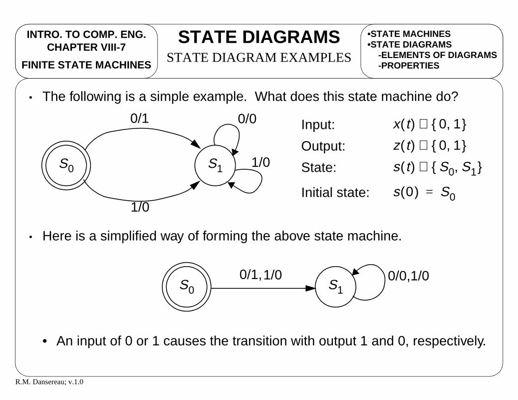
• The following is a simple example. What does this state machine do?
• Here is a simplified way of forming the above state machine.
• An input of 0 or 1 causes the transition with output 1 and 0, respectively.
S0 S1
0/1
1/0
x t( ) 0 1,{ }∈Input:
z t( ) 0 1,{ }∈Output:
s t( ) S0 S1,{ }∈State:
s 0( ) S0=Initial state:
0/0
1/0
S0 S10/1,1/0 0/0,1/0

R.M. Dansereau; v.1.0
INTRO. TO COMP. ENG.CHAPTER VIII-8
STATE DIAGRAMSBIT FLIPPER EXAMPLE
FINITE STATE MACHINES
•STATE DIAGRAMS-ELEMENTS OF DIAGRAMS-PROPERTIES-STATE DIAGRAM EX.
• Consider the simple bit flipper looked at the in previous chapter. How
would a state diagram be formed?
• Below is one possible way of drawing the state diagram for the bit flipper.
• Since the bit flipper is a Moore machine, the state diagram can also be
S0 S1
-/1
-/0
S0 0⁄ S1 1⁄
-
-

R.M. Dansereau; v.1.0
INTRO. TO COMP. ENG.CHAPTER VIII-9
STATE DIAGRAMSPATTERN DETECT EXAMPLE
FINITE STATE MACHINES
•STATE DIAGRAMS-PROPERTIES-STATE DIAGRAM EX.-BIT FLIPPER EX.
• Suppose we want a sequential system that has the following behaviour
• Effectively, the system should output a 1 when the last set of four inputs
have been 1101.
• For instance, the following output z(t) is obtained for the input x(t)
x t( ) 0 1,{ }∈Input:
z t( ) 0 1,{ }∈Output:
z t( )1 if x t 3 t,–( ) 1101=
0 otherwise
=Function:
100100100100110101101101001101001
???000000000000100001001000001000
x t( )z t( )
t 0123456789...
R.M. Dansereau; v.1.0
INTRO. TO COMP. ENG.CHAPTER VIII-10
STATE DIAGRAMSPATTERN DETECT EXAMPLE
FINITE STATE MACHINES
•STATE DIAGRAMS-STATE DIAGRAM EX.-BIT FLIPPER EX.-PATTERN DETECT EX.
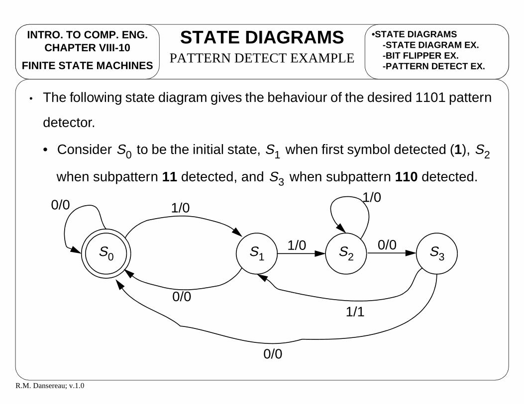
• The following state diagram gives the behaviour of the desired 1101 pattern
detector.
• Consider to be the initial state, when first symbol detected (1),
when subpattern 11 detected, and when subpattern 110 detected.
S0 S1 S2
S3
S0 S1
1/0
0/0
S2 S30/01/0
1/1
0/0 1/0
0/0

R.M. Dansereau; v.1.0
INTRO. TO COMP. ENG.CHAPTER VIII-11
STATE TABLESINTRODUCTION
FINITE STATE MACHINES
•STATE DIAGRAMS-STATE DIAGRAM EX.-BIT FLIPPER EX.-PATTERN DETECT EX.
• State tables also express a systems behaviour and consists of
• Present state
• The present state of the system, typically given in binary encoded
form or with . So, a state of in our state diagram with 10
states would be represented as 0101 since we require 4 bits.
• Inputs
• Whatever external inputs used to cause the state transitions.
• Next state
• The next state, generally in binary encoded form.
• Outputs
• Whatever outputs, other then the state, for the system. Note that
there would be no outputs in a Moore machine.
Sk S5
R.M. Dansereau; v.1.0
INTRO. TO COMP. ENG.CHAPTER VIII-12
STATE TABLESBIT FLIPPER EXAMPLE
FINITE STATE MACHINES
•STATE DIAGRAMS•STATE TABLES
-INTRODUCTION
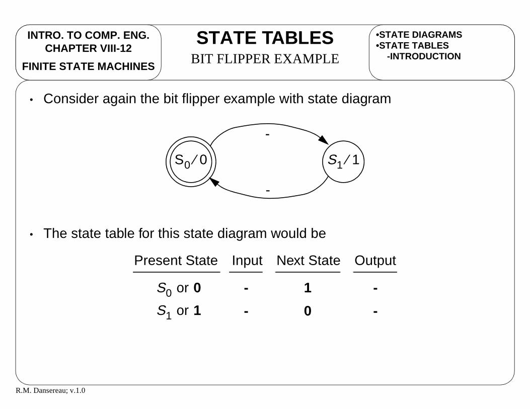
• Consider again the bit flipper example with state diagram
• The state table for this state diagram would be
S0 0⁄ S1 1⁄
-
-
Present State Next StateInput Output
-
-
1
0
-
-S1 or 1
S0 or 0

R.M. Dansereau; v.1.0
INTRO. TO COMP. ENG.CHAPTER VIII-13
STATE TABLESTRANSLATE FROM DIAGRAM
FINITE STATE MACHINES
•STATE DIAGRAMS•STATE TABLES
-INTRODUCTION-BIT FLIPPER EX.
• From a state diagram, a state table is fairly easy to obtain.
• Determine the number of states in the state diagram.
• If there are states and 1-bit inputs, then there will be rows in
the state table.
• Example: If there are 3 states and 2 1-bit inputs, each state will
have possible inputs, for a total of 3*4=12 rows.
• Write out for each state, the possible input rows.
• For each state/input pair, follow the directed arc in the state diagram to
determine the next state and the output.
m n m2n
22 4=
2n

R.M. Dansereau; v.1.0
INTRO. TO COMP. ENG.CHAPTER VIII-14
STATE TABLESPATTERN DETECT EXAMPLE
FINITE STATE MACHINES
•STATE TABLES-INTRODUCTION-BIT FLIPPER EX.-TRANSLATE DIAGRAM
• If we consider the pattern detection example previously discussed, the
following would be the state table.
Present State Next StateInput Output
0
1
0
0
S0
0 0
1 0
0 0
1 0
0 0
1 1
or 0 0
P1 P0 X Z
S0 or 0 0
S1 or 0 1
S1 or 0 1
S2 or 1 0
S2 or 1 0
S3 or 1 1
S3 or 1 1
S0 or 0 0
S1 or 0 1
S0 or 0 0
S2 or 1 0
S3 or 1 1
S2 or 1 0
S0 or 0 0
S1 or 0 1
N1 N0
R.M. Dansereau; v.1.0
INTRO. TO COMP. ENG.CHAPTER VIII-15
STATE TABLESTRANSLATE TO DIAGRAM
FINITE STATE MACHINES
•STATE TABLES-BIT FLIPPER EX.-TRANSLATE DIAGRAM-PATTERN DETECT EX.
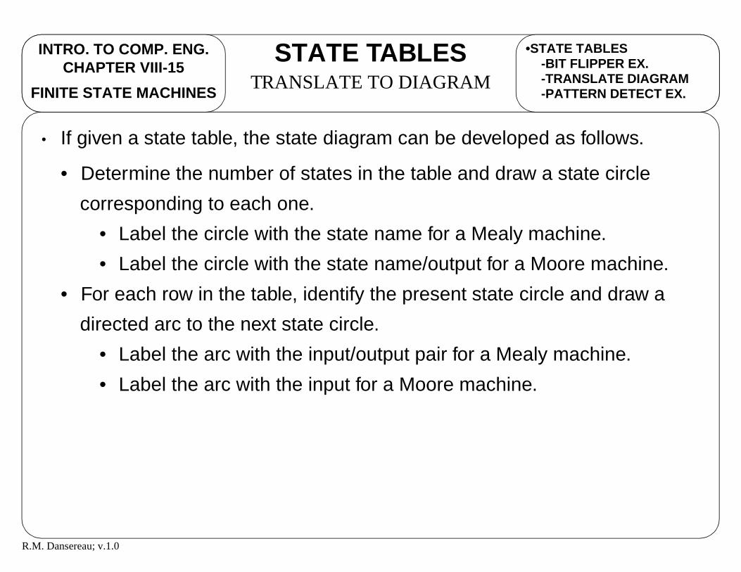
• If given a state table, the state diagram can be developed as follows.
• Determine the number of states in the table and draw a state circle
corresponding to each one.
• Label the circle with the state name for a Mealy machine.
• Label the circle with the state name/output for a Moore machine.
• For each row in the table, identify the present state circle and draw a
directed arc to the next state circle.
• Label the arc with the input/output pair for a Mealy machine.
• Label the arc with the input for a Moore machine.

R.M. Dansereau; v.1.0
INTRO. TO COMP. ENG.CHAPTER VIII-16
SEQ. CIRCUITSINTRODUCTION
FINITE STATE MACHINES
•STATE TABLES-TRANSLATE DIAGRAM-PATTERN DETECT EX.-TRANSLATE TO DIAGRAM
• With the descriptions of a FSM as a state diagram and a state table, the
next question is how to develop a sequential circuit, or logic diagram from
the FSM.
• Effectively, we wish to form a circuit as follows.
InputsCombinational
Network
State
Outputs(Mealy machine)
Outputs(Moore machine)
φ1φ2
FF
φ1φ2
FF
Present State Next State

R.M. Dansereau; v.1.0
INTRO. TO COMP. ENG.CHAPTER VIII-17
SEQ. CIRCUITSFROM STATE TABLE
FINITE STATE MACHINES
•STATE TABLES•SEQUENTIAL CIRCUITS
-INTRODUCTION
• The procedure for developing a logic circuit from a state table is the same
as with a regular truth table.
• Generate Boolean functions for
• each external outputs using external inputs and present state bits
• each next state bit using external inputs and present state bits
• Use Boolean algebra, Karnaugh maps, etc. as normal to simplify.
• Draw a register for each state bit.
• Draw logic diagram components connecting external outputs to external
inputs and outputs of state bit registers (which have the present state).
• Draw logic diagram components connecting inputs of state bits (for next
state) to the external inputs and outputs of state bit registers (which have
the present state).

R.M. Dansereau; v.1.0
INTRO. TO COMP. ENG.CHAPTER VIII-18
SEQ. CIRCUITSPATTERN DETECT EXAMPLE
FINITE STATE MACHINES
•STATE TABLES•SEQUENTIAL CIRCUITS
-INTRODUCTION-DEVEL. LOGIC CIRCUITS
• Following the procedure outlined, Boolean functions for the pattern
detector state table can be formed using Karnaugh maps as follows.
0 1 0 0
1 0 1 0
0
1
00 01 11 10P1P0
X
0 0 1 0
1 1 0 0
0
1
00 01 11 10P1P0
X
0 0 0 0
0 0 1 0
0
1
00 01 11 10P1P0
X
N1 XP1 XP1P0+=
N0 XP1P0 XP1P0 XP1P0+ + XP1P0 X P1 P0⊕( )+= =
N1 N0 Z
Z XP1P0=

R.M. Dansereau; v.1.0
INTRO. TO COMP. ENG.CHAPTER VIII-19
SEQ. CIRCUITSPATTERN DETECT EXAMPLE
FINITE STATE MACHINES
•SEQUENTIAL CIRCUITS-INTRODUCTION-DEVEL. LOGIC CIRCUITS-PATTERN DETECT EX.
• Notice that the previous Boolean functions can also be expressed with time
as follows.
• An important thing to note in these equations is the relation between the
present states P and the next states N.
N1 t( ) P1 t 1+( ) X t( ) P1 t( ) X t( ) P1 t( ) P0 t( )⋅⋅+⋅= =
N0 t( ) P0 t 1+( ) X t( ) P1 t( ) P0 t( )⋅ ⋅ X t( ) P1 t( ) P0 t( )⋅⋅+= =
X t( ) P1 t( ) P0 t( )⋅ ⋅+
Z t( ) X P1 t( ) P0 t( )⋅⋅=
X t( ) P1 t( ) P0 t( )⋅ ⋅ X t( ) P1 t( ) P0 t( )⊕⋅+=
R.M. Dansereau; v.1.0
INTRO. TO COMP. ENG.CHAPTER VIII-20
SEQ. CIRCUITSPATTERN DETECT EXAMPLE
FINITE STATE MACHINES
•SEQUENTIAL CIRCUITS-INTRODUCTION-DEVEL. LOGIC CIRCUITS-PATTERN DETECT EX.
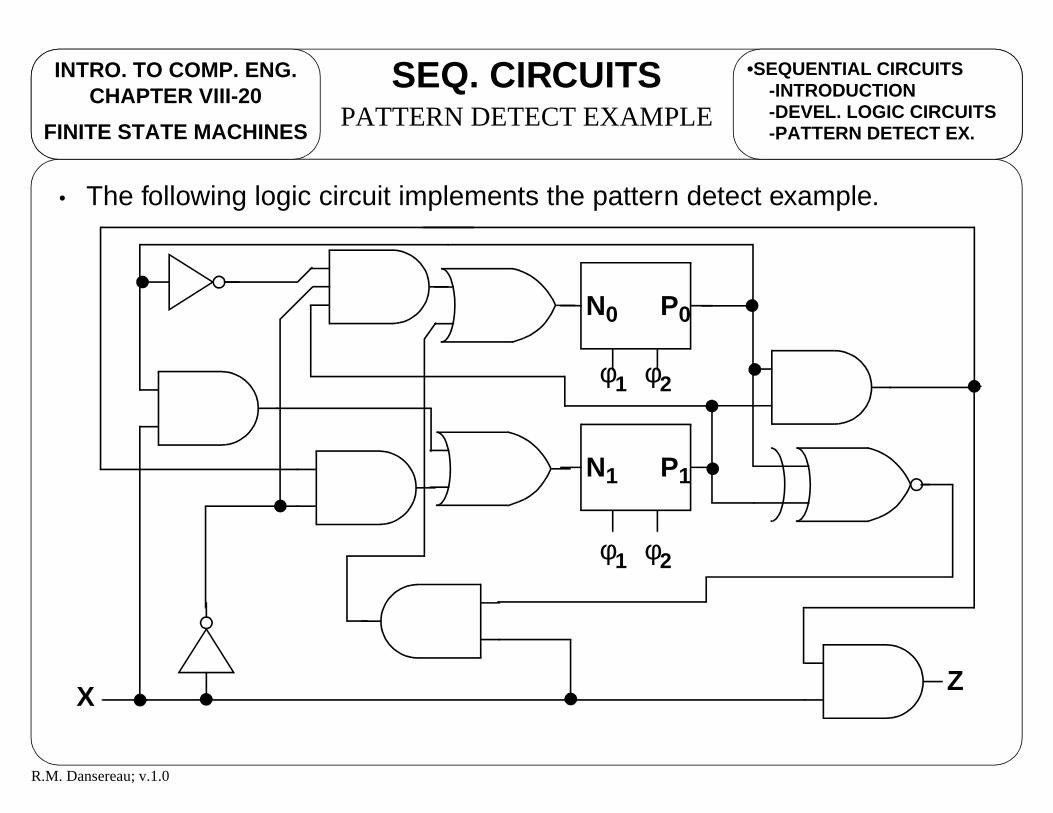
• The following logic circuit implements the pattern detect example.
Z
P1
φ1 φ2
P0
φ1 φ2
X
N1
N0

R.M. Dansereau; v.1.0
INTRO. TO COMP. ENG.CHAPTER VIII-21
FSM EXAMPLESEXAMPLE #1
FINITE STATE MACHINES
•SEQUENTIAL CIRCUITS-INTRODUCTION-DEVEL. LOGIC CIRCUITS-PATTERN DETECT EX.
• Consider the following system description.
• A sequential system has
• One input = {a, b, c}
• One output = {p, q}
• Output is
• q when input sequence has even # of a’s and odd # of b’s
• p otherwise

R.M. Dansereau; v.1.0
INTRO. TO COMP. ENG.CHAPTER VIII-22
FSM EXAMPLESEXAMPLE #1
FINITE STATE MACHINES
•SEQUENTIAL CIRCUITS•FSM EXAMPLES
-EXAMPLE #1
• We can begin forming a state machine for the system description by
reviewing the possible states. In addition, assign each state a state name.
• : even # of a’s and even # of b’s / output is p
• : even # of a’s and odd # of b’s / output is q
• : odd # of a’s and odd # of b’s / output is p
• : odd # of a’s and even # of b’s / output is p
• Note that this machine can be a Moore machine. So, we can associate the
output with each state.
SEE
SEO
SOO
SOE

R.M. Dansereau; v.1.0
INTRO. TO COMP. ENG.CHAPTER VIII-23
FSM EXAMPLESEXAMPLE #1
FINITE STATE MACHINES
•SEQUENTIAL CIRCUITS•FSM EXAMPLES
-EXAMPLE #1
• Now draw a circle with each state.
SEE p⁄ SEO q⁄ SOO p⁄ SOE p⁄
R.M. Dansereau; v.1.0
INTRO. TO COMP. ENG.CHAPTER VIII-24
FSM EXAMPLESEXAMPLE #1
FINITE STATE MACHINES
•SEQUENTIAL CIRCUITS•FSM EXAMPLES
-EXAMPLE #1
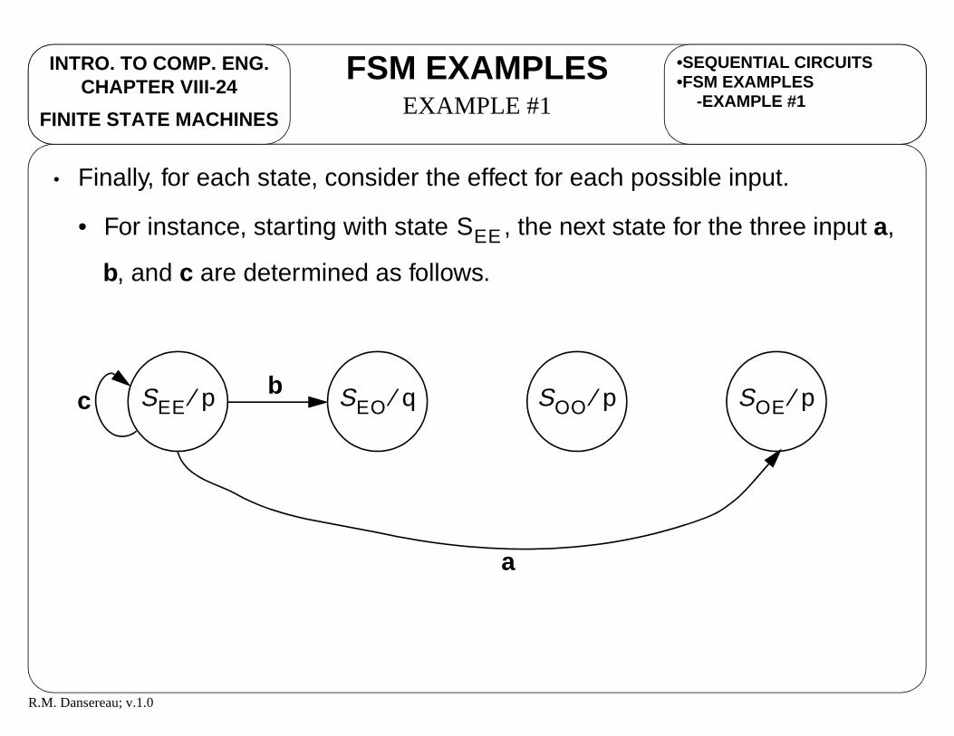
• Finally, for each state, consider the effect for each possible input.
• For instance, starting with state , the next state for the three input a,
b, and c are determined as follows.
SEE
SEE p⁄ SEO q⁄ SOO p⁄ SOE p⁄c
a
b

R.M. Dansereau; v.1.0
INTRO. TO COMP. ENG.CHAPTER VIII-25
FSM EXAMPLESEXAMPLE #1
FINITE STATE MACHINES
•SEQUENTIAL CIRCUITS•FSM EXAMPLES
-EXAMPLE #1
• Finishing the state diagram, the following is obtained.
SEE p⁄ SEO q⁄ SOO p⁄ SOE p⁄c
a
b
c
a
b a
b
c
b
a
c
R.M. Dansereau; v.1.0
INTRO. TO COMP. ENG.CHAPTER VIII-26
FSM EXAMPLESEXAMPLE #1
FINITE STATE MACHINES
•SEQUENTIAL CIRCUITS•FSM EXAMPLES
-EXAMPLE #1
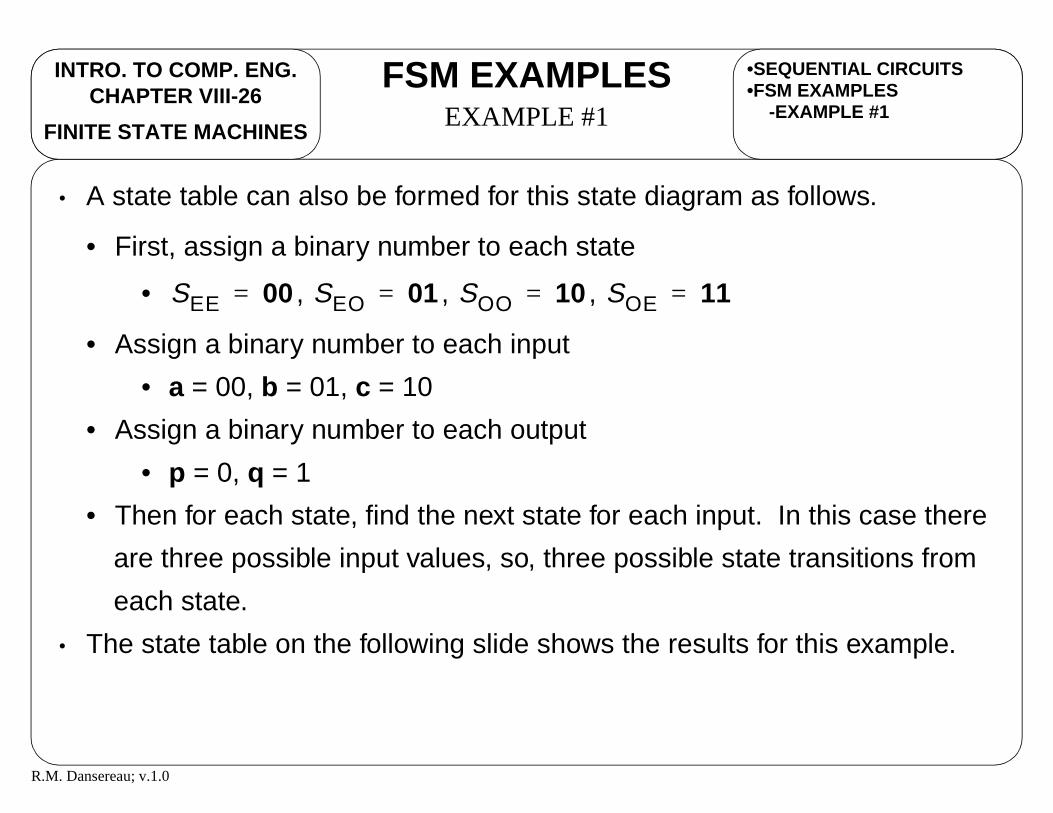
• A state table can also be formed for this state diagram as follows.
• First, assign a binary number to each state
• , , ,
• Assign a binary number to each input
• a = 00, b = 01, c = 10
• Assign a binary number to each output
• p = 0, q = 1
• Then for each state, find the next state for each input. In this case there
are three possible input values, so, three possible state transitions from
each state.
• The state table on the following slide shows the results for this example.
SEE 00= SEO 01= SOO 10= SOE 11=

R.M. Dansereau; v.1.0
INTRO. TO COMP. ENG.CHAPTER VIII-27
FSM EXAMPLESEXAMPLE #1
FINITE STATE MACHINES
•SEQUENTIAL CIRCUITS•FSM EXAMPLES
-EXAMPLE #1
Present State Next StateInput Output
a = 00 p = 00 0
P1 P0 X Z
1 1
N1 N0
b = 01 p = 00 0 0 1c = 10 p = 00 0 0 0a = 00 q = 10 1 1 0b = 01 q = 10 1 0 0c = 10 q = 10 1 0 1a = 00 p = 01 0 0 1b = 01 p = 01 0 1 1c = 10 p = 01 0 1 0a = 00 p = 01 1 0 0b = 01 p = 01 1 1 0c = 10 p = 01 1 1 1
SEE =SEE =SEE =SEO =SEO =SEO =SOO =SOO =SOO =SOE =SOE =SOE =
SOE =SEO =SEE =SOO =SEE =SEO =SEO =SOE =SOO =SEE =SOO =SOE =
R.M. Dansereau; v.1.0
INTRO. TO COMP. ENG.CHAPTER VIII-28
FSM EXAMPLESEXAMPLE #1
FINITE STATE MACHINES
•SEQUENTIAL CIRCUITS•FSM EXAMPLES
-EXAMPLE #1
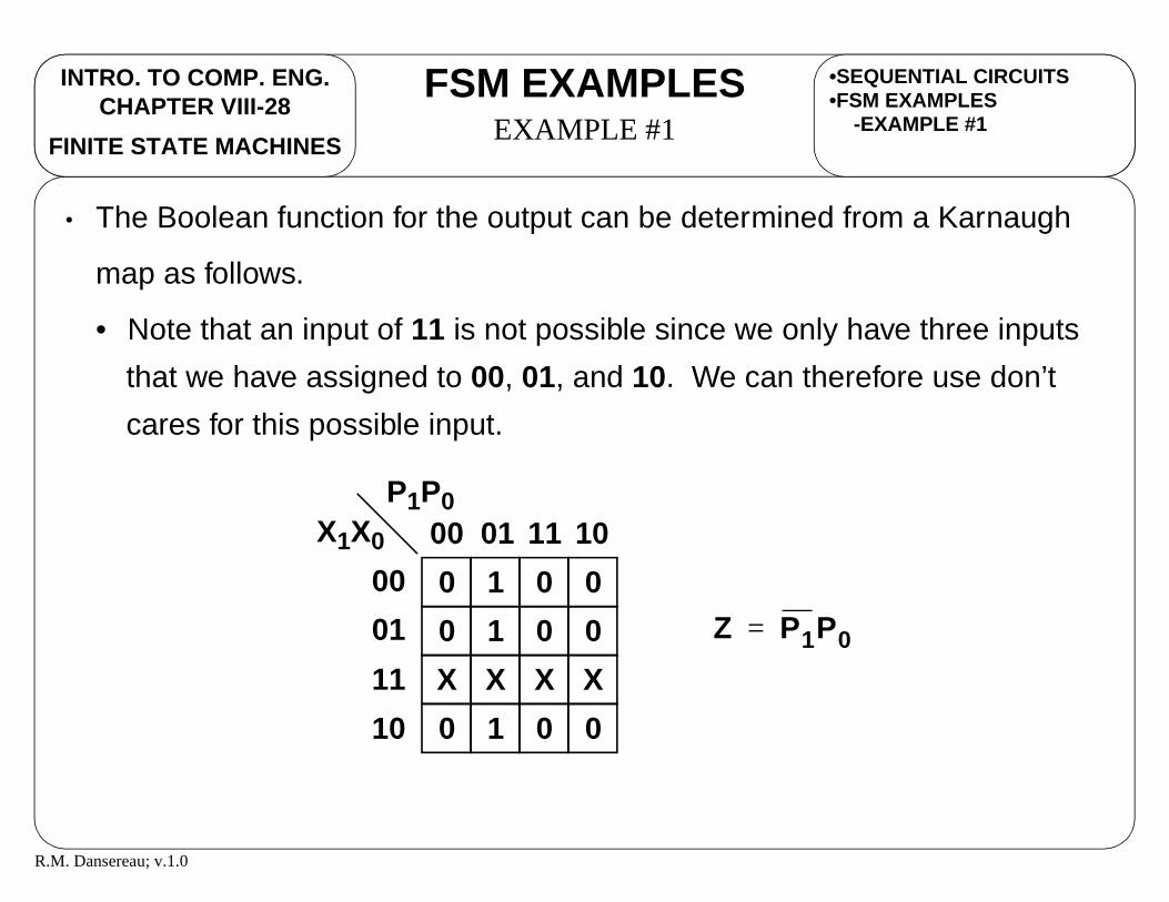
• The Boolean function for the output can be determined from a Karnaugh
map as follows.
• Note that an input of 11 is not possible since we only have three inputs
that we have assigned to 00, 01, and 10. We can therefore use don’t
cares for this possible input.
0 1 0 0
0 1 0 0
X X X X
0 1 0 0
00
01
11
10
00 01 11 10X1X0
P1P0
Z P1P0=

R.M. Dansereau; v.1.0
INTRO. TO COMP. ENG.CHAPTER VIII-29
FSM EXAMPLESEXAMPLE #1
FINITE STATE MACHINES
•SEQUENTIAL CIRCUITS•FSM EXAMPLES
-EXAMPLE #1
• The Boolean function for the next state bit can also be determined from
Karnaugh maps as follows.
1 1 0 0
0 0 1 1
X X X X
0 0 1 1
00
01
11
10
00 01 11 10X1X0
P1P0
1 0 0 1
1 0 0 1
X X X X
0 1 1 0
00
01
11
10
00 01 11 10X1X0
P1P0
N0 P0X1 P0X1+ P0 X1⊕= =N1 P1 X1 X0⊕ ⊕=

R.M. Dansereau; v.1.0
INTRO. TO COMP. ENG.CHAPTER VIII-30
FSM EXAMPLESEXAMPLE #1
FINITE STATE MACHINES
•SEQUENTIAL CIRCUITS•FSM EXAMPLES
-EXAMPLE #1
• The following logic circuit can be made with these Boolean functions.
P1
φ1 φ2
P0
φ1 φ2
N1
N0
Z
X1
X0
N0 P0 X1⊕=
N1 P1 X1 X0⊕ ⊕=
Z P1P0=

R.M. Dansereau; v.1.0
INTRO. TO COMP. ENG.CHAPTER VIII-31
FSM EXAMPLESEXAMPLE #2
FINITE STATE MACHINES
•SEQUENTIAL CIRCUITS•FSM EXAMPLES
-EXAMPLE #1
• A sequential circuit is defined by the following Boolean functions with input
, present states , , and , and next states , , and .
•
•
•
•
• Derive the state table.
• Derive the state diagram.
X P0 P1 P2 N0 N1 N2
N2 X P1 P0⊕( ) X P1 P0⊕( )+=
N1 P2=
N0 P1=
Z XP1P2=

R.M. Dansereau; v.1.0
INTRO. TO COMP. ENG.CHAPTER VIII-32
FSM EXAMPLESEXAMPLE #2
FINITE STATE MACHINES
•SEQUENTIAL CIRCUITS•FSM EXAMPLES
-EXAMPLE #1-EXAMPLE #2
• The state table is formed as follows.
Present State Next StateInput Output
0 00 0
P1 P0 X ZN1 N0P2 N2
0 0 011 00 00 0 000 00 10 0 001 00 10 0 010 01 00 0 101 01 00 0 110 01 10 0 111 01 10 0 100 00 01 1 011 00 01 1 000 00 11 1 001 00 11 1 010 01 01 1 101 11 01 1 110 01 11 1 111 11 11 1 10

R.M. Dansereau; v.1.0
INTRO. TO COMP. ENG.CHAPTER VIII-33
FSM EXAMPLESEXAMPLE #2
FINITE STATE MACHINES
•SEQUENTIAL CIRCUITS•FSM EXAMPLES
-EXAMPLE #1-EXAMPLE #2
• The state diagram can be drawn as follows.
S1S0 S2 S3
S4 S5 S6 S7
0/0
1/0
0/0
1/0
0/0
1/0 0/0
1/0
0/0
1/00/0
1/0
0/0
1/1
0/0
1/1