Embed Size (px)
Citation preview
99Output FunctiOnsChapterChapterChapter
In This Chapter...Runtime Changes to CTRIO Configured Preset Tables (DL PLCs) ...........................9–2
Pulse Output Profiles (DL PLCs) ................................................................................9–5
Trapezoid Profile .......................................................................................................9–6
S-Curve Profile ...........................................................................................................9–7
Symmetrical S-Curve Profile ......................................................................................9–8
Home Search Profile ..................................................................................................9–9
Free Form Profile .....................................................................................................9–12
Pulse Output Status/Control Bits and Command Codes (DL PLCs) ......................9–13
DirectLOGIC Programming Examples Overview ....................................................9–19
Trapezoid with Limits Profile ..................................................................................9–20
Trapezoid with Limits (CTRIO2) Profile ..................................................................9–21
Trapezoid Plus (CTRIO2) Profile ..............................................................................9–28
Dynamic Positioning Plus and Dynamic Positioning Profiles .................................9–34
Dynamic Positioning Plus (CTRIO2) Profile ............................................................9–35
Dynamic Positioning/Positioning Plus Example .....................................................9–41
Dynamic Velocity Profile ..........................................................................................9–42
Velocity Mode .........................................................................................................9–48
Run to Limit Mode .................................................................................................9–54
Run to Position Mode .............................................................................................9–61
Run to Position Mode ..............................................................................................9–67
Run to Position Mode Example ...............................................................................9–68
Raw Output ..............................................................................................................9–69

Runtime Changes to CTRIO Configured Preset Tables (DL PLCs)
Presets and preset tables can be set up entirely within CTRIO Workbench so that no program control is necessary to assign discrete Preset Tables to CTRIO Input Functions.
You can make runtime edits to presets/preset tables from your control program. To make a runtime change, a series of commands must be executed which will pass new values to a preset table or call a different pre-configured table.
Command Codes are passed to the CTRIO(2) module to effect the required edit. Each Command Code has its own syntax, and all Command Codes must be presented in a particular sequence:
• The command code and associated parameters must be loaded into the appropriate memory locations.
• A Process Command instruction must be passed to the CTRIO(2) module.
• A Command Complete signal must be received and the Command Error bit must stay at zero.
• Finally, the Enable Output instruction must be passed to the CTRIO(2) module.
Some changes require a combination of Command Codes so those changes must follow the steps above for each Command Code processed (Output Control and Status Offsets are listed in order of Output 0 - Output 3).
In order to process a command, first the program must load the Command and Required Word and DWord Parameters. Then the program should turn ON the Process Command bit and look for the CTRIO(2) module to acknowledge the command with the Command Complete bit. Finally the program should reset the Process Command bit and set the Enable Output bit when appropriate. If the Command Error bit is received, the CTRIO(2) module was unable to process the command due to an illegal value in either the Command Code or Parameter fields.
Control Bit(transfers from CPU to CTRIO(2))
Bit Offsets: WinPLC, EBC, PBC, DEVNETS, MODBUS
V-memory OffsetsDirectLOGIC PLCs
Enable Output 32, 40, 48, 56 26.0, 26.8, 27.0, 27.8
Process Command 39, 47, 55, 63 26.7, 26.15, 27.7, 27.15
Status Bit(transfers from CTRIO(2) to CPU)
Bit Offsets: WinPLC, EBC, PBC, DEVNETS, MODBUS
V-memory OffsetsDirectLOGIC PLCs
Command Error 38, 46, 54, 62 22.6, 22.14, 23.6, 23.14
Command Complete 39, 47, 55, 63 22.7, 22.15, 23.7, 23.15
Word Control CPU to CTRIO(2)
Word Offsets: WinPLC, EBC, PBC, DEVNETS, MODBUS
V-memory Offsets from Output Start (octal)
Command Code 0, 6 10, 16Word Parameter 1 1, 7 11, 17
Word Parameter 2 2, 8 12, 20
DWord Parameter 3 0, 2 0, 4
DL
Win
NI
���
DL
Win
NI
���
DL
Win
NI
���
DL
Win
NI
���
Counter I/O User Manual, 3rd Edition9–2
Chapter 9: Output Functions
1
2
3
4
5
6
7
8
9
10
11
12
13
14
A
B
C
D
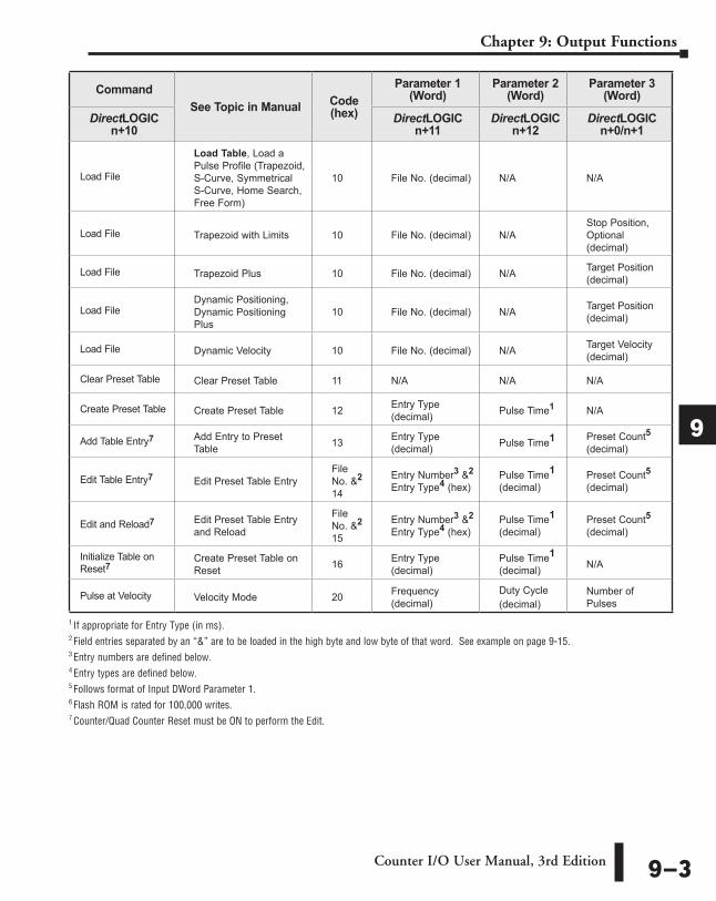
CommandSee Topic in Manual Code
(hex)
Parameter 1 (Word)
Parameter 2 (Word)
Parameter 3 (Word)
DirectLOGIC n+10
DirectLOGIC n+11
DirectLOGIC n+12
DirectLOGIC n+0/n+1
Load File
Load Table, Load a Pulse Profile (Trapezoid, S-Curve, Symmetrical S-Curve, Home Search, Free Form)
10 File No. (decimal) N/A N/A
Load File Trapezoid with Limits 10 File No. (decimal) N/AStop Position, Optional (decimal)
Load File Trapezoid Plus 10 File No. (decimal) N/A Target Position (decimal)
Load FileDynamic Positioning, Dynamic Positioning Plus
10 File No. (decimal) N/A Target Position (decimal)
Load File Dynamic Velocity 10 File No. (decimal) N/A Target Velocity (decimal)
Clear Preset Table Clear Preset Table 11 N/A N/A N/A
Create Preset Table Create Preset Table 12 Entry Type (decimal) Pulse Time1 N/A
Add Table Entry7 Add Entry to Preset Table 13 Entry Type
(decimal) Pulse Time1 Preset Count5 (decimal)
Edit Table Entry7 Edit Preset Table EntryFile No. &2 14
Entry Number3 &2
Entry Type4 (hex)Pulse Time1 (decimal)
Preset Count5 (decimal)
Edit and Reload7 Edit Preset Table Entry and Reload
File No. &2 15
Entry Number3 &2 Entry Type4 (hex)
Pulse Time1 (decimal)
Preset Count5 (decimal)
Initialize Table on Reset7
Create Preset Table on Reset 16 Entry Type
(decimal)Pulse Time1 (decimal) N/A
Pulse at Velocity Velocity Mode 20 Frequency (decimal)
Duty Cycle (decimal)
Number of Pulses
1 If appropriate for Entry Type (in ms).2 Field entries separated by an “&” are to be loaded in the high byte and low byte of that word. See example on page 9-15.3 Entry numbers are defined below.4 Entry types are defined below.5 Follows format of Input DWord Parameter 1.6 Flash ROM is rated for 100,000 writes.7 Counter/Quad Counter Reset must be ON to perform the Edit.
Counter I/O User Manual, 3rd Edition 9–3
Chapter 9: Output Functions
1
2
3
4
5
6
7
8
9
10
11
12
13
14
A
B
C
D
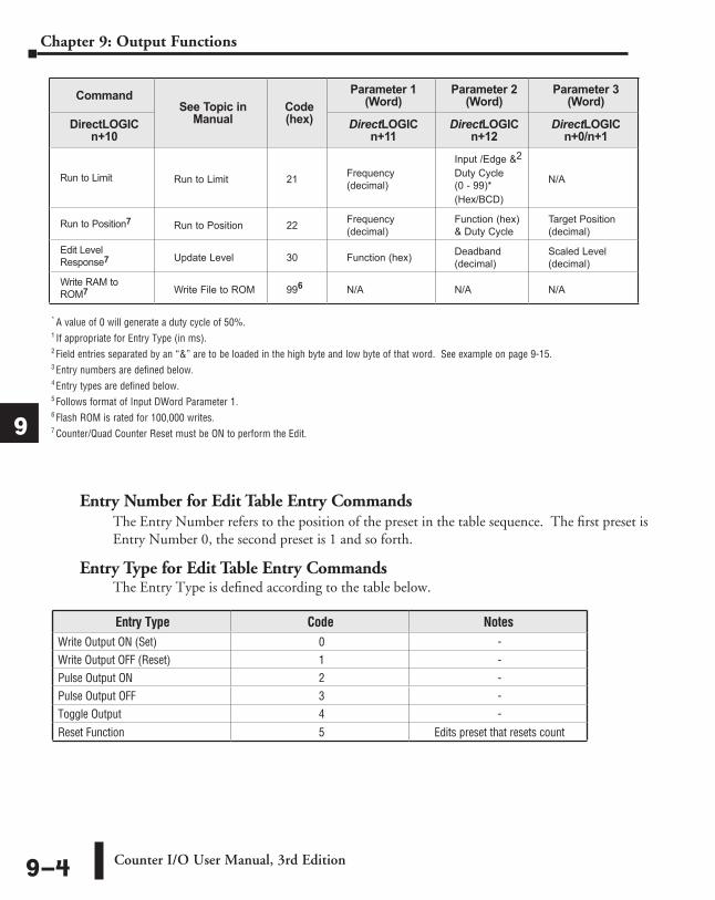
* A value of 0 will generate a duty cycle of 50%.1 If appropriate for Entry Type (in ms).2 Field entries separated by an “&” are to be loaded in the high byte and low byte of that word. See example on page 9-15.3 Entry numbers are defined below.4 Entry types are defined below.5 Follows format of Input DWord Parameter 1.6 Flash ROM is rated for 100,000 writes.7 Counter/Quad Counter Reset must be ON to perform the Edit.
Entry Type Code NotesWrite Output ON (Set) 0 -Write Output OFF (Reset) 1 -Pulse Output ON 2 -Pulse Output OFF 3 -Toggle Output 4 -
Reset Function 5 Edits preset that resets count
Entry Number for Edit Table Entry CommandsThe Entry Number refers to the position of the preset in the table sequence. The first preset is Entry Number 0, the second preset is 1 and so forth.
Entry Type for Edit Table Entry CommandsThe Entry Type is defined according to the table below.
CommandSee Topic in
ManualCode (hex)
Parameter 1 (Word)
Parameter 2 (Word)
Parameter 3 (Word)
DirectLOGIC n+10
DirectLOGIC n+11
DirectLOGIC n+12
DirectLOGIC n+0/n+1
Run to Limit Run to Limit 21 Frequency (decimal)
Input /Edge &2
Duty Cycle (0 - 99)*(Hex/BCD)
N/A
Run to Position7 Run to Position 22 Frequency (decimal)
Function (hex) & Duty Cycle
Target Position (decimal)
Edit Level Response7 Update Level 30 Function (hex) Deadband
(decimal)Scaled Level (decimal)
Write RAM to ROM7 Write File to ROM 996 N/A N/A N/A
Counter I/O User Manual, 3rd Edition9–4
Chapter 9: Output Functions
1
2
3
4
5
6
7
8
9
10
11
12
13
14
A
B
C
D
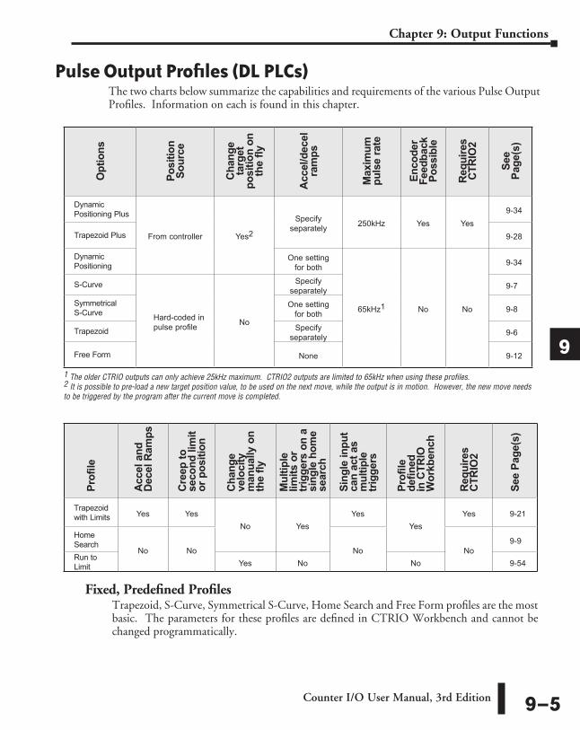
Pulse Output Profiles (DL PLCs)The two charts below summarize the capabilities and requirements of the various Pulse Output Profiles. Information on each is found in this chapter.
1 The older CTRIO outputs can only achieve 25kHz maximum. CTRIO2 outputs are limited to 65kHz when using these profiles.2 It is possible to pre-load a new target position value, to be used on the next move, while the output is in motion. However, the new move needs to be triggered by the program after the current move is completed.
Opt
ions
Posi
tion
Sour
ce
Cha
nge
targ
et
posi
tion
on
the
fly
Acc
el/d
ecel
ra
mps
Max
imum
pu
lse
rate
Enco
der
Feed
back
Po
ssib
le
Req
uire
s C
TRIO
2
See
Page
(s)
Dynamic Positioning Plus
From controller Yes2
Specify separately 250kHz Yes Yes
9-34
Trapezoid Plus 9-28
Dynamic Positioning
One setting for both
65kHz1 No No
9-34
S-Curve
Hard-coded in pulse profile No
Specify separately 9-7
Symmetrical S-Curve
One setting for both 9-8
Trapezoid Specify separately 9-6
Free Form None 9-12
Fixed, Predefined ProfilesTrapezoid, S-Curve, Symmetrical S-Curve, Home Search and Free Form profiles are the most basic. The parameters for these profiles are defined in CTRIO Workbench and cannot be changed programmatically.
Profi
le
Acc
el a
nd
Dec
el R
amps
Cre
ep to
se
cond
lim
it or
pos
ition
Cha
nge
velo
city
m
anua
lly o
n th
e fly
Mul
tiple
lim
its o
r tri
gger
s on
a
sing
le h
ome
sear
ch
Sing
le in
put
can
act a
s m
ultip
le
trigg
ers
Profi
le
defin
ed
in C
TRIO
W
orkb
ench
Req
uire
s C
TRIO
2
See
Page
(s)
Trapezoid with Limits Yes Yes
No YesYes
YesYes 9-21
Home Search
No No No No9-9
Run to Limit Yes No No 9-54
Counter I/O User Manual, 3rd Edition 9–5
Chapter 9: Output Functions
1
2
3
4
5
6
7
8
9
10
11
12
13
14
A
B
C
D
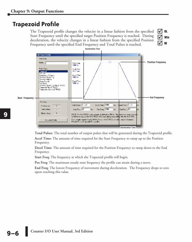
Trapezoid ProfileThe Trapezoid profile changes the velocity in a linear fashion from the specified Start Frequency until the specified target Position Frequency is reached. During deceleration, the velocity changes in a linear fashion from the specified Position Frequency until the specified End Frequency and Total Pulses is reached.
Total Pulses: The total number of output pulses that will be generated during the Trapezoid profile.
Accel Time: The amount of time required for the Start Frequency to ramp up to the Position Frequency.
Decel Time: The amount of time required for the Position Frequency to ramp down to the End Frequency.
Start Freq: The frequency at which the Trapezoid profile will begin.
Pos Freq: The maximum steady state frequency the profile can attain during a move.
End Freq: The lowest Frequency of movement during deceleration. The Frequency drops to zero upon reaching this value.
Position Frequency
Start Frequency End Frequency
Acceleration Time
Deceleration Time
DL
Win
NI
���
DL
Win
NI
���
DL
Win
NI
���
DL
Win
NI
���
Counter I/O User Manual, 3rd Edition9–6
Chapter 9: Output Functions
1
2
3
4
5
6
7
8
9
10
11
12
13
14
A
B
C
D
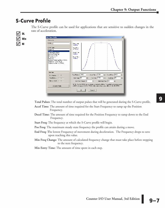
S-Curve ProfileThe S-Curve profile can be used for applications that are sensitive to sudden changes in the rate of acceleration.
Total Pulses: The total number of output pulses that will be generated during the S-Curve profile.
Accel Time: The amount of time required for the Start Frequency to ramp up the Position Frequency.
Decel Time: The amount of time required for the Position Frequency to ramp down to the End Frequency.
Start Freq: The frequency at which the S-Curve profile will begin.
Pos Freq: The maximum steady state frequency the profile can attain during a move.
End Freq: The lowest Frequency of movement during deceleration. The Frequency drops to zero upon reaching this value.
Min Freq Change: The amount of calculated frequency change that must take place before stepping to the next frequency.
Min Entry Time: The amount of time spent in each step.
DL
Win
NI
���
DL
Win
NI
���
DL
Win
NI
���
DL
Win
NI
���
Counter I/O User Manual, 3rd Edition 9–7
Chapter 9: Output Functions
1
2
3
4
5
6
7
8
9
10
11
12
13
14
A
B
C
D
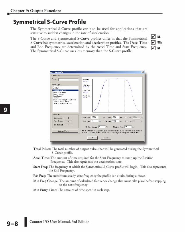
Symmetrical S-Curve ProfileThe Symmetrical S-Curve profile can also be used for applications that are sensitive to sudden changes in the rate of acceleration.
The S-Curve and Symmetrical S-Curve profiles differ in that the Symmetrical S-Curve has symmetrical acceleration and deceleration profiles. The Decel Time and End Frequency are determined by the Accel Time and Start Frequency. The Symmetrical S-Curve uses less memory than the S-Curve profile.
Total Pulses: The total number of output pulses that will be generated during the Symmetrical S-Curve profile.
Accel Time: The amount of time required for the Start Frequency to ramp up the Position Frequency. This also represents the deceleration time.
Start Freq: The frequency at which the Symmetrical S-Curve profile will begin. This also represents the End Frequency.
Pos Freq: The maximum steady state frequency the profile can attain during a move.
Min Freq Change: The amount of calculated frequency change that must take place before stepping to the next frequency
Min Entry Time: The amount of time spent in each step.
DL
Win
NI
���
DL
Win
NI
���
DL
Win
NI
���
DL
Win
NI
���
Counter I/O User Manual, 3rd Edition9–8
Chapter 9: Output Functions
1
2
3
4
5
6
7
8
9
10
11
12
13
14
A
B
C
D
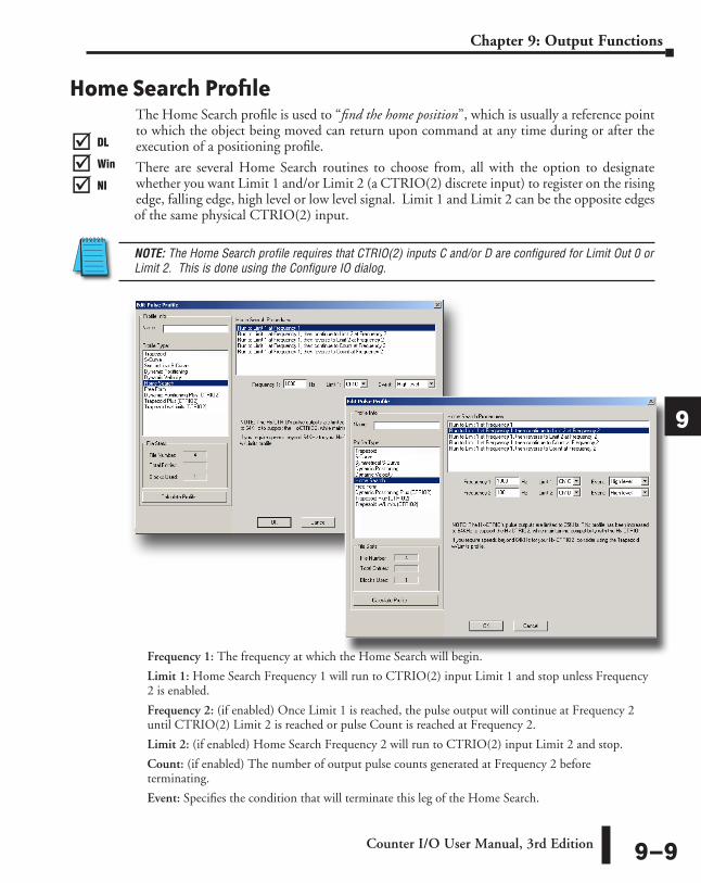
Home Search ProfileThe Home Search profile is used to “find the home position”, which is usually a reference point to which the object being moved can return upon command at any time during or after the execution of a positioning profile.
There are several Home Search routines to choose from, all with the option to designate whether you want Limit 1 and/or Limit 2 (a CTRIO(2) discrete input) to register on the rising edge, falling edge, high level or low level signal. Limit 1 and Limit 2 can be the opposite edges of the same physical CTRIO(2) input.
NOTE: The Home Search profile requires that CTRIO(2) inputs C and/or D are configured for Limit Out 0 or Limit 2. This is done using the Configure IO dialog.
Frequency 1: The frequency at which the Home Search will begin.
Limit 1: Home Search Frequency 1 will run to CTRIO(2) input Limit 1 and stop unless Frequency 2 is enabled.
Frequency 2: (if enabled) Once Limit 1 is reached, the pulse output will continue at Frequency 2 until CTRIO(2) Limit 2 is reached or pulse Count is reached at Frequency 2.
Limit 2: (if enabled) Home Search Frequency 2 will run to CTRIO(2) input Limit 2 and stop.
Count: (if enabled) The number of output pulse counts generated at Frequency 2 before terminating.
Event: Specifies the condition that will terminate this leg of the Home Search.
DL
Win
NI
���
DL
Win
NI
���
DL
Win
NI
���
DL
Win
NI
���
Counter I/O User Manual, 3rd Edition 9–9
Chapter 9: Output Functions
1
2
3
4
5
6
7
8
9
10
11
12
13
14
A
B
C
D

Home Search Routines1: Run to Limit 1 at Frequency 1.
2: Run to Limit 1 at Frequency 1, then continue to Limit 2 at Frequency 2.
3: Run to Limit 1 at Frequency 1, then reverse to Limit 2 at Frequency 2.
Limit 1 (Home)
Frequency 1
PositionVe
loci
ty
Limit 2 (Home)
Frequency 1
Limit 1
Position
Velo
city Frequency 2
Limit 2 (Home)
Frequency 1
Limit 1
Position
Velo
city
Frequency 2
Counter I/O User Manual, 3rd Edition9–10
Chapter 9: Output Functions
1
2
3
4
5
6
7
8
9
10
11
12
13
14
A
B
C
D
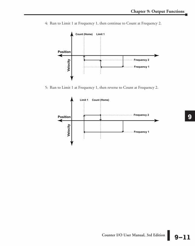
4: Run to Limit 1 at Frequency 1, then continue to Count at Frequency 2.
5: Run to Limit 1 at Frequency 1, then reverse to Count at Frequency 2.
Count (Home)
Frequency 1
Limit 1
Position
Velo
city Frequency 2
Count (Home)
Frequency 1
Limit 1
Position
Velo
city
Frequency 2
Counter I/O User Manual, 3rd Edition 9–11
Chapter 9: Output Functions
1
2
3
4
5
6
7
8
9
10
11
12
13
14
A
B
C
D
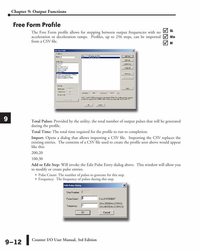
Free Form ProfileThe Free Form profile allows for stepping between output frequencies with no acceleration or deceleration ramps. Profiles, up to 256 steps, can be imported from a CSV file.
Total Pulses: Provided by the utility, the total number of output pulses that will be generated during the profile.
Total Time: The total time required for the profile to run to completion.
Import: Opens a dialog that allows importing a CSV file. Importing the CSV replaces the existing entries. The contents of a CSV file used to create the profile seen above would appear like this:
200,20
100,30
Add or Edit Step: Will invoke the Edit Pulse Entry dialog above. This window will allow you to modify or create pulse entries.
• Pulse Count: The number of pulses to generate for this step. • Frequency: The frequency of pulses during this step.
DL
Win
NI
���
DL
Win
NI
���
DL
Win
NI
���
DL
Win
NI
���
Counter I/O User Manual, 3rd Edition9–12
Chapter 9: Output Functions
1
2
3
4
5
6
7
8
9
10
11
12
13
14
A
B
C
D

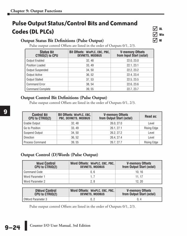
Pulse Output Status/Control Bits and Command Codes (DL PLCs)
Output Status Bit Definitions (Pulse Output)Pulse output control Offsets are listed in the order of Outputs 0/1, 2/3.
Output Control Bit Definitions (Pulse Output)Pulse output control Offsets are listed in the order of Outputs 0/1, 2/3.
Output Control (D)Words (Pulse Output)
Pulse output control Offsets are listed in the order of Outputs 0/1, 2/3.
Word Control CPU to CTRIO(2)
Word Offsets: WinPLC, EBC, PBC, DEVNETS, MODBUS
V-memory Offsets from Output Start (octal)
Command Code 0, 6 10, 16Word Parameter 1 1, 7 11, 17
Word Parameter 2 2, 8 12, 20
DWord Control CPU to CTRIO(2)
Word Offsets: WinPLC, EBC, PBC, DEVNETS, MODBUS
V-memory Offsets from Output Start (octal)
DWord Parameter 3 0, 2 0, 4
Control Bit CPU to CTRIO(2)
Bit Offsets: WinPLC, EBC, PBC, DEVNETS, MODBUS
V-memory Offsets from Output Start (octal) Read as:
Enable Output 32, 48 26.0, 27.0 LevelGo to Position 33, 49 26.1, 27.1 Rising EdgeSuspend Output 34, 50 26.2, 27.2 Level Direction 36, 52 26.4, 27.4 Level
Process Command 39, 55 26.7, 27.7 Rising Edge
Status Bit CTRIO(2) to CPU
Bit Offsets: WinPLC, EBC, PBC, DEVNETS, MODBUS
V-memory Offsets from Input Start (octal)
Output Enabled 32, 48 22.0, 23.0Position Loaded 33, 49 22.1, 23.1Output Suspended 34, 50 22.2, 23.2Output Active 36, 52 22.4, 23.4Output Stalled 37, 53 22.5, 23.5Command Error 38, 54 22.6, 23.6
Command Complete 39, 55 22.7, 23.7
DL
Win
NI
���
DL
Win
NI
���
DL
Win
NI
���
DL
Win
NI
���
Counter I/O User Manual, 3rd Edition 9–13
Chapter 9: Output Functions
1
2
3
4
5
6
7
8
9
10
11
12
13
14
A
B
C
D

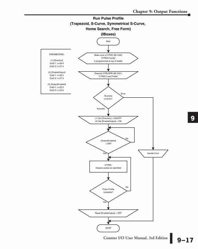
Trapezoid, S-Curve, Symmetrical S-Curve, Home Search, Free Form ProfilesFor predefined Trapezoid, S-Curve, Symmetrical S-Curve, Home Search and Free Form profiles, the program must prepare the Load Table command (see table on next page), by selecting Command Code = 0010 Hex/BCD and setting Word Parameter 1 to the File number of the profile (example: File 1 Trapezoid 1). Then the program sets the process Command bit and watches for the Command Complete bit. Then the program will clear the process Command bit and set the Direction bit (if necessary) and finally the Enable Output bit to start the output pulses.
Clearing the Enable Output bit will always suspend pulsing and reset any profile in progress to it’s beginning. Once complete, the profile remains loaded and can be restarted by clearing the Enable Output, changing the Direction bit (if desired), and again setting the Enable Output.
For the Home Search routine, a CTRIO(2) input must be assigned to Limit by the CTRIO Workbench Configure I/O dialog.
NOTE: For a Home Search Profile, if you are at the home position and the Home Search profile is initiated, there will not be any pulse outputs.
A Pulse Profile programming example, that loads and runs a pulse profile implementing the bit/(D)Word addressing suggested in the table on the page 9-16, is discussed in pages following.
DL
Win
NI
���
DL
Win
NI
���
DL
Win
NI
���
DL
Win
NI
���
Counter I/O User Manual, 3rd Edition9–14
Chapter 9: Output Functions
1
2
3
4
5
6
7
8
9
10
11
12
13
14
A
B
C
D

Command Code and Parameter Definitions
Where the fields of the Parameters in the table above are separated by an “&” character, this indicates a code with different definitions for each byte (high byte and low byte). For example, to enter the Pulse Output to Limit command, set the high byte of the Word Parameter 2 to the Edge used to terminate the output pulses (see definition following), and set the low byte to the desired duty cycle.
In order to process a command, first the program must load the Command Code and required DWord, Word, and bit parameters (DWord and Word values for pulse outputs are unsigned integers). Then the program will turn ON the process Command bit and look for the CTRIO(2) module to acknowledge the command with the Command Complete bit. Finally, the program will reset the process Command bit and set the Enable Output bit when appropriate. If the Command Error bit is received, the CTRIO(2) module was unable to process the command due to an illegal value in either the Command Code or parameter files.
.
* A value of 0 will generate a duty cycle of 50%
Command Code (Hex/BCD)
Word Parameter 1 (decimal) Word Parameter 2 DWord Parameter 3
Load File from ROM 10
File Number Trapezoid or S-curve Symmetrical S-Curve
Home Search N/A
N/A
Load File from ROM 10 File Number Dynamic Positioning Target Position (decimal)
Load File from ROM 10 File Number Dynamic Velocity Target Velocity (decimal)
Velocity Mode 20Run Frequency
(CTRIO: 20Hz - 25KHz CTRIO2: 20Hz - 64KHz)
Duty Cycle (0 to 99)* (decimal) Number of Pulses (decimal)
Run to Limit Mode 21Run Frequency
(CTRIO: 20Hz - 25KHz CTRIO2: 20Hz - 64KHz)
Input / Edge & Duty Cycle (0 to 99)*
(Hex/BCD)N/A
Run to Position Mode 22Run Frequency
(CTRIO: 20Hz - 25KHz CTRIO2: 20Hz - 64KHz)
Compare Function & Duty Cycle (0 to 99)*
(Hex/BCD)
Desired Input Function Value (decimal)
Counter I/O User Manual, 3rd Edition 9–15
Chapter 9: Output Functions
1
2
3
4
5
6
7
8
9
10
11
12
13
14
A
B
C
D

Running a Trapezoid, S-Curve, Symmetrical S-Curve Profile, Home Search or Free Form Profile on CTRIO(2) Y0 & Y1
The required basic steps for a DL-PLC to run a Trapezoid, S-Curve, Symmetrical S-Curve profile, Home Search or Free Form profile are outlined in this table. The steps coordinate with the flow chart steps on page 9-21 (left hand side). Pulse Output Status/Control Bits are shown on the following page.
Steps NamePLC Control
Outputs Base Addr = V2030 (Bit-of-Word)
PLC Status Inputs Base
Addr = V2000 (Bit-of-Word)
PLC Control Outputs Base Addr = V2030
(Control Relay) D2-240
PLC Status Inputs Base
Addr = V2000 (Control Relay)
D2-240
Action
1Command
Code V2040
N/A
V2040
N/A
Set to 10 (Load Stored Profile)
2
Parameter 1 V2041 V2041 File # of stored profile, determined by user
Parameter 3 V2031 - V2030 V2031 - V2030
Target Position: User Defined (DWord)
Target Position is only used with Trapezoid Plus and Trapezoid with
Limits
3 Process Command V2056.7 C227 Turn ON until Command Complete
status bit is returned (see step 4)
4Command Complete
Status N/AV2022.7
N/AC127 When ON, Profile is now loaded,
clear Process Command bit (step 3)
5 Command Error V2022.6 C126 ON if Command or Parameters are
invalid
6 Set Direction V2056.4
N/AC224
N/ASet ON or OFF for Direction of Rotation
7 Enable Output V2056.0 C220 Turn ON to start pulses
8 Output Enable Status
N/A
V2022.0
N/A
C120 When ON, module is confirming Enable Output
9Output Active Status
V2022.4 C124When ON, module is pulsing, OFF
with Enable Status ON = profile has completed
10 Disable Output V2056.0
N/AC220
N/A
Turn OFF when pulse status is OFF and Enable Status is ON
11 Suspend Output V2056.2 C222 Turn ON to “pause” output pulses
without resetting pulse count
12 Output Suspended N/A V2022.2 N/A C122 ON when out pulse train has been
suspended
DL
Win
NI
���
DL
Win
NI
���
DL
Win
NI
���
DL
Win
NI
���
Counter I/O User Manual, 3rd Edition9–16
Chapter 9: Output Functions
1
2
3
4
5
6
7
8
9
10
11
12
13
14
A
B
C
D
Start
Run Pulse Profile(Trapezoid, S-Curve, Symmetrical S-Curve,
Home Search, Free Form)(IBoxes)
Error
Success
PARAMETERS:
(1) [Direction]Out0-1: n+26.4Out2-3: n+27.4
(2) [EnableOutput]Out0-1: n+26.0Out2-3: n+27.0
(3) [OutputEnabled]Out0-1: n+22.0Out2-3: n+23.0
CTRIO:Outputs pulses as specified
Execute CTRLDPR (IB-1001)"CTRIO Load Profile"
Successor Error?
(1) Set [Direction] = ON/OFF(2) Set [EnableOutput] = ON
STOP
Handle Error
[OutputEnabled]= ON?
No
Yes
Pulse Profilecomplete?
Reset [EnableOutput] = OFF
No
Yes
Make sure a CTRIO (IB-1000)"CTRIO Config"
is programmed at top of ladder
Counter I/O User Manual, 3rd Edition 9–17
Chapter 9: Output Functions
1
2
3
4
5
6
7
8
9
10
11
12
13
14
A
B
C
D

Start
Run Pulse Profile(Trapezoid, S-Curve, Symmetrical S-Curve,
Home Search, Free Form)(DL-PLC)
Yes
No
[CmdComplete]= ON?
Yes
No
PARAMETERS:
(1) [CommandCode]:Out0-1: n+10Out2-3: n+16
(2) [Parameter1]Out0-1: n+11Out2-3: n+17
(3) [ProcessCmd]Out0-1: n+26.7Out2-3: n+27.7
(4) [CmdComplete]Out0-1: n+22.7Out2-3: n+23.7
(5) [CmdError]Out0-1: n+22.6Out2-3: n+23.6
(6) [Direction]Out0-1: n+26.4Out2-3: n+27.4
(7) [EnableOutput]Out0-1: n+26.0Out2-3: n+27.0
(8) [OutputEnabled]Out0-1: n+22.0Out2-3: n+23.0
CTRIO:Outputs pulses as specified
(1) Set [CommandCode] = 10 (hex)(2) Set [Parameter1] = File # (decimal)
(3) Set [ProcessCmd] = ON
[CmdError]= ON?
(1) Reset [ProcessCmd] = OFF(2) Set [Direction] = ON/OFF(3) Set [EnableOutput] = ON
STOP
Handle Error
[OutputEnabled]= ON?
No
Yes
Pulse Profilecomplete?
Reset [EnableOutput] = OFF
No
Yes
Counter I/O User Manual, 3rd Edition9–18
Chapter 9: Output Functions
1
2
3
4
5
6
7
8
9
10
11
12
13
14
A
B
C
D
DirectLOGIC Programming Examples OverviewNOTE: The DirectSOFT programming examples provided on the following pages are simple examples that are intended to assist you in the basics of loading and running various output pulse profiles. The examples are complete enough to load a profile, process the command and load the Parameter registers necessary to execute the profile. Two System Functions examples are also provided.
Load and Run a Pulse Profile Example: You will need to have a Trapezoid, S-Curve, Symmetrical S-Curve, Home Search or Free Form profile configured using the Configure I/O dialog. You will also need to have the appropriate Pulse Profile Table File Number (decimal) stored in V3000 for this example. You must turn C0 on to load and run the pulse profile. C2 controls the pulse output direction.
The example program on the following page loads and executes a Pulse Profile that was created using CTRIO Workbench Pulse Profiles dialog. This example can be used for Trapezoid, S-Curve, Symmetrical S-Curve, Home Search and Free Form profiles (Home Search requires that CTRIO inputs C and/or D are configured for Limit Out 0 and/or Limit Out 2). The Pulse Profile number is stored in V3000 for this example. Turning on C0 will load and run the pulse profile.
DL
Win
NI
���
DL
Win
NI
���
DL
Win
NI
���
DL
Win
NI
���
Counter I/O User Manual, 3rd Edition 9–19
Chapter 9: Output Functions
1
2
3
4
5
6
7
8
9
10
11
12
13
14
A
B
C
D
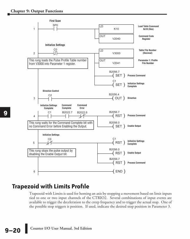
Trapezoid with Limits ProfileTrapezoid with Limits is used for homing an axis by stopping a movement based on limit inputs tied to one or two input channels of the CTRIO2. Several combinations of input events are available to trigger the deceleration to the creep frequency and to trigger the actual stop. One of the possible stop triggers is position. If used, indicate the desired stop position in Parameter 3.
SP0
K10LD
V2040OUT
1
( )SET
C1
C0
V3000LD
V2041OUT
2
( )OUT
B2056.4
( )SET
B2056.7
C1 B2022.7 B2022.6
( )RST
B2056.7
( )SET
B2056.0
C0
( )RST
C1
( )RST
B2056.0
( )END6
DirectSOFT 32
3
4
C2
( )RST
B2056.7
5
First Scan
Load Table Command 0x10 (Hex)
Command Code Register
Table File Number (Decimal)
Parameter 1: Profile File Number
Direction
Process Command
Initialize Settings Complete
Process Command
Enable Output
Initialize Settings Complete
Enable Output
Initialize Settings
Initialize Settings Complete
Command Complete
Command Error
Initialize Settings
This rung waits for the Command Complete bit with no Command Error before Enabling the Output.
This rung loads the Pulse Profile Table number from V3000 into Parameter 1 register.
Direction Control
Process Command
This rung stops the pulse output by disabling the Enable Output bit.
Counter I/O User Manual, 3rd Edition9–20
Chapter 9: Output Functions
1
2
3
4
5
6
7
8
9
10
11
12
13
14
A
B
C
D
Trapezoid with Limits (CTRIO2) ProfileTrapezoid with Limits (CTRIO2) profile is only available when using a CTRIO2 module. Trapezoid with Limits is a homing routine, typically used to find a hard reference point for the axis. There are other routines to home an axis, but this is typically the one to use. The profile is a homing routine similar to Home Search but has five additional features:
1. The profile is trapezoidal (has linear accel and decel rates), allowing for faster homing routines without stalling the stepper.
2. The profile can be asymmetrical. (Accel and Decel rates are separate)3. Encoder Feedback can be added, useful for correcting excessive lash or slippage in the
system.4. Allows output rates up to 250kHz.5. When Stop Trigger is position, it is a variable (parameter 3 in the output memory
map), set by the base controller.
NOTE: When using an input channel as the Stop Trigger with this profile, the Stop Trigger must be beyond the first limit in the same direction. The output cannot change direction to reach the second limit. Use Home Search if the output must Reverse to Limit 2.
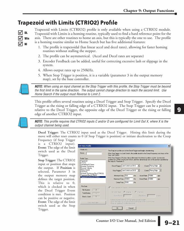
This profile offers several routines using a Decel Trigger and Stop Trigger. Specify the Decel Trigger as the rising or falling edge of a CTRIO2 input. The Stop Trigger can be a position relative to the Decel Trigger, the opposite edge of the Decel Trigger or the rising or falling edge of another CTRIO2 input.
NOTE: This profile requires that CTRIO2 inputs C and/or D are configured for Limit Out X, where X is the output channel being used.
Decel Trigger: The CTRIO2 input used as the Decel Trigger. Hitting this limit during the move will either reset counts to 0 (if Stop Trigger is position) or initiate deceleration to the Creep Frequency (if Stop Trigger is a CTRIO2 input). Event: The edge of the limit switch used as the Decel Trigger.
Stop Trigger: The CTRIO2 input or position that stops the output. If Position is selected, Parameter 3 in the output memory map defines the target position. This is relative to 0, which is clocked in when the Decel Trigger Event condition is met. Position can be positive or negative. Event: The edge of the limit switch used as the Stop Trigger.
DL
Win
NI
���
DL
Win
NI
���
DL
Win
NI
���
DL
Win
NI
���
Counter I/O User Manual, 3rd Edition 9–21
Chapter 9: Output Functions
1
2
3
4
5
6
7
8
9
10
11
12
13
14
A
B
C
D
Minimum Freq: The frequency at which the profile will begin and end.
Maximum Freq: The maximum steady state frequency the profile can attain during a move.
Accel Rate: The rate at which the output frequency will increase during the acceleration period.
Decel Rate: The rate at which the output frequency will decrease when Decel Trigger is reached.
Creep Freq: The (slower) rate to use between the Decel Trigger and the Stop Trigger.
Encoder Input: Select the channel where the encoder is connected.
Scale Factor: This is the output to input resolution (stepper/encoder) ratio. In other words, if the stepper motor being used is a 1000 ppr (pulses per revolution) and the encoder is 800 ppr, then the scale factor would be 1000/800 = 1.25.
Deadband: This is the number of position counts away from the target position that causes no action. This can reduce “hunting” or “ringing” as the profile attempts to get to the target position. Be sure to include a deadband when the encoder has a higher resolution than the stepper.
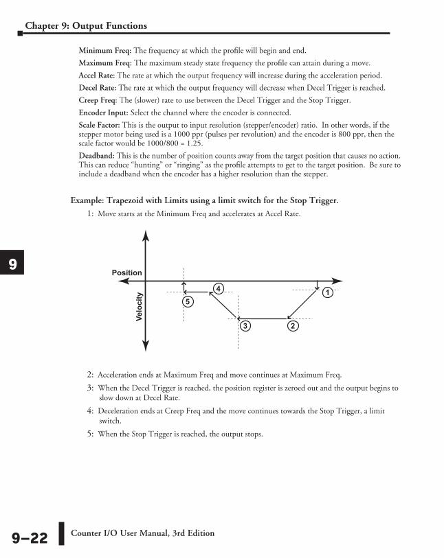
Example: Trapezoid with Limits using a limit switch for the Stop Trigger.
1: Move starts at the Minimum Freq and accelerates at Accel Rate.
2: Acceleration ends at Maximum Freq and move continues at Maximum Freq.
3: When the Decel Trigger is reached, the position register is zeroed out and the output begins to slow down at Decel Rate.
4: Deceleration ends at Creep Freq and the move continues towards the Stop Trigger, a limit switch.
5: When the Stop Trigger is reached, the output stops.
Position
Velocity
45
23
1
Counter I/O User Manual, 3rd Edition9–22
Chapter 9: Output Functions
1
2
3
4
5
6
7
8
9
10
11
12
13
14
A
B
C
D
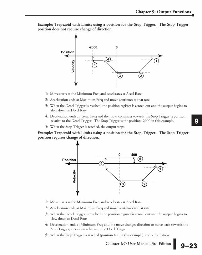
Example: Trapezoid with Limits using a position for the Stop Trigger. The Stop Trigger position does not require change of direction.
1: Move starts at the Minimum Freq and accelerates at Accel Rate.
2: Acceleration ends at Maximum Freq and move continues at that rate.
3: When the Decel Trigger is reached, the position register is zeroed out and the output begins to slow down at Decel Rate.
4: Deceleration ends at Creep Freq and the move continues towards the Stop Trigger, a position relative to the Decel Trigger. The Stop Trigger is the position -2000 in this example.
5: When the Stop Trigger is reached, the output stops.
Example: Trapezoid with Limits using a position for the Stop Trigger. The Stop Trigger position requires change of direction.
1: Move starts at the Minimum Freq and accelerates at Accel Rate.
2: Acceleration ends at Maximum Freq and move continues at that rate.
3: When the Decel Trigger is reached, the position register is zeroed out and the output begins to slow down at Decel Rate.
4: Deceleration ends at Minimum Freq and the move changes direction to move back towards the Stop Trigger, a position relative to the Decel Trigger.
5: When the Stop Trigger is reached (position 400 in this example), the output stops.
Position
Velocity
45
23
1
-2000 0
Position
Velo
city
4
23
1
0 4005
Counter I/O User Manual, 3rd Edition 9–23
Chapter 9: Output Functions
1
2
3
4
5
6
7
8
9
10
11
12
13
14
A
B
C
D
Pulse Output Status/Control Bits and Command Codes (DL PLCs)
Output Status Bit Definitions (Pulse Output)Pulse output control Offsets are listed in the order of Outputs 0/1, 2/3.
Output Control Bit Definitions (Pulse Output)Pulse output control Offsets are listed in the order of Outputs 0/1, 2/3.
Output Control (D)Words (Pulse Output)
Pulse output control Offsets are listed in the order of Outputs 0/1, 2/3.
Word Control CPU to CTRIO(2)
Word Offsets: WinPLC, EBC, PBC, DEVNETS, MODBUS
V-memory Offsets from Output Start (octal)
Command Code 0, 6 10, 16Word Parameter 1 1, 7 11, 17
Word Parameter 2 2, 8 12, 20
DWord Control CPU to CTRIO(2)
Word Offsets: WinPLC, EBC, PBC, DEVNETS, MODBUS
V-memory Offsets from Output Start (octal)
DWord Parameter 3 0, 2 0, 4
Control Bit CPU to CTRIO(2)
Bit Offsets: WinPLC, EBC, PBC, DEVNETS, MODBUS
V-memory Offsets from Output Start (octal) Read as:
Enable Output 32, 48 26.0, 27.0 LevelGo to Position 33, 49 26.1, 27.1 Rising EdgeSuspend Output 34, 50 26.2, 27.2 Level Direction 36, 52 26.4, 27.4 Level
Process Command 39, 55 26.7, 27.7 Rising Edge
Status Bit CTRIO(2) to CPU
Bit Offsets: WinPLC, EBC, PBC, DEVNETS, MODBUS
V-memory Offsets from Input Start (octal)
Output Enabled 32, 48 22.0, 23.0Position Loaded 33, 49 22.1, 23.1Output Suspended 34, 50 22.2, 23.2Output Active 36, 52 22.4, 23.4Output Stalled 37, 53 22.5, 23.5Command Error 38, 54 22.6, 23.6
Command Complete 39, 55 22.7, 23.7
DL
Win
NI
���
DL
Win
NI
���
DL
Win
NI
���
DL
Win
NI
���
Counter I/O User Manual, 3rd Edition9–24
Chapter 9: Output Functions
1
2
3
4
5
6
7
8
9
10
11
12
13
14
A
B
C
D
Start
Run Trapezoid With Limits(IBoxes)
Error
Success
PARAMETERS:
(1) [Parameter3]Out0-1: n+0-1Out2-3: n+4-5
(2) [Direction ]Out0-1: n+26.4Out2-3: n+27.4
(3) [EnableOutput]Out0-1: n+26.0Out2-3: n+27.0
(4) [OutputEnabled]Out0-1: n+22.0Out2-3: n+23.0
(5) [OutputActive]Out0-1: n+22.4Out2-3: n+23.4
Execute CTRLDPR (IB-1001)"CTRIO Load Profile"
Successor Error?
Handle Error
CTRIO:Outputs pulses as specified
STOP
Stop Trigger= Position?
Yes
No
Reset [EnableOutput] = OFF
Yes
(1) Set [Direction] = ON/OFF(2) Set [EnableOutput] = ON
Set [Parameter3] = Position
[OutputEnabled]= ON?
No
Yes
No
Make sure a CTRIO (IB-1000)"CTRIO Config"
is programmed at top of ladder
[OutputActive]= ON?
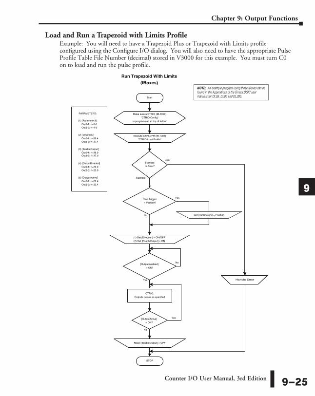
NOTE: An example program using these IBoxes can be found in the Appendices of the DirectLOGIC user manuals for DL05, DL06 and DL205.
Load and Run a Trapezoid with Limits ProfileExample: You will need to have a Trapezoid Plus or Trapezoid with Limits profile configured using the Configure I/O dialog. You will also need to have the appropriate Pulse Profile Table File Number (decimal) stored in V3000 for this example. You must turn C0 on to load and run the pulse profile.
Counter I/O User Manual, 3rd Edition 9–25
Chapter 9: Output Functions
1
2
3
4
5
6
7
8
9
10
11
12
13
14
A
B
C
D

NOTE: An example program using these IBoxes can be found in the Appendices of the DirectLOGIC user manuals for DL05, DL06 and DL205. START
Run Trapezoid With Limits(DL-PLC)
STOP
(3) Set [ProcessCmd] = ON
[CmdComplete]= ON?
(1) Set [CommandCode] = 10 (hex)(2) Set [Parameter1] = File # (decimal)
PARAMETERS:
Out2-3: n + 16
(1) [CommandCode]:Out0-1: n + 10
Out2-3: n + 17
(2) [Parameter1]:Out0-1: n + 11
Out2-3: n + 4-5
(3) [Parameter3]:Out0-1: n + 0-1
Out2-3: n + 27.7
(4) [ProcessCmd]:Out0-1: n + 26.7
Out2-3: n + 23.7
(5) [CmdComplete]:Out0-1: n + 22.7
Out2-3: n + 23.6
(6) [CmdError]:Out0-1: n + 22.6
Out2-3: n + 27.4
(7) [Direction]:Out0-1: n + 26.4
Out2-3: n + 27.0
(8) [EnableOutput]:Out0-1: n + 26.0
Out2-3: n + 23.0
(9) [OutputEnabled]:Out0-1: n + 22.0
Out2-3: n + 23.4
(10) [OutputActive]:Out0-1: n + 22.4
Reset [ProcessCmd] = OFF
Reset [EnableOutput] = OFF
Set [Parameter3] = Position
(1) Set [Direction] = ON/OFF(2) Set [EnableOutput] = ON
Yes
No
Yes
No
Yes
Yes
Yes
No
No
No
[CmdError]= ON?
[OutputEnabled]
Handle Error
= ON?
[OutputActive]= ON?
CTRIOOutputs pulses as specified
Stop Trigger= Position?
Counter I/O User Manual, 3rd Edition9–26
Chapter 9: Output Functions
1
2
3
4
5
6
7
8
9
10
11
12
13
14
A
B
C
D
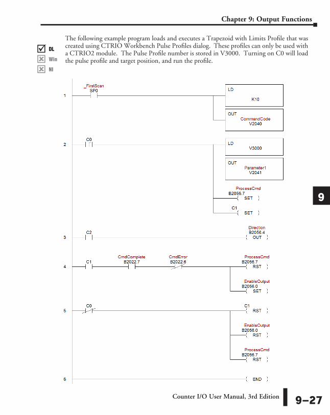
The following example program loads and executes a Trapezoid with Limits Profile that was created using CTRIO Workbench Pulse Profiles dialog. These profiles can only be used with a CTRIO2 module. The Pulse Profile number is stored in V3000. Turning on C0 will load the pulse profile and target position, and run the profile.
DL
Win
NI
���
DL
Win
NI
���
DL
Win
NI
���
DL
Win
NI
���
Counter I/O User Manual, 3rd Edition 9–27
Chapter 9: Output Functions
1
2
3
4
5
6
7
8
9
10
11
12
13
14
A
B
C
D

Trapezoid Plus (CTRIO2) ProfileTrapezoid Plus
Trapezoid Plus is used for executing trapezoidal moves to a position value. The desired position is specified in Parameter 3. In a Trapezoid Plus profile, it is possible to pre-load a new target position value, to be used on the next move, while the output is in motion. However, the new move needs to be triggered by the program after the current move is completed. In addition, this profile allows for different acceleration and deceleration rates. The proper sequence of events for using this profile can be found in the previous flow charts and those that follow.
The Trapezoid Plus (CTRIO2) profile is only available when using a CTRIO2 module. See Trapezoid description for a general description of this profile. The profile resembles Trapezoid Profile, but has four additional features:
1: The target position is a variable (Parameter 3 in the output memory map) set by the base controller, instead of a constant specified in the profile.
2: The profile can be asymmetrical (Accel and Decel rates are separate).
3: Encoder Feedback can be added, useful for correcting excessive lash or slippage in the system.
4: Allows output rates up to 250kHz.
DL
Win
NI
���
DL
Win
NI
���
DL
Win
NI
���
DL
Win
NI
���
Counter I/O User Manual, 3rd Edition9–28
Chapter 9: Output Functions
1
2
3
4
5
6
7
8
9
10
11
12
13
14
A
B
C
D
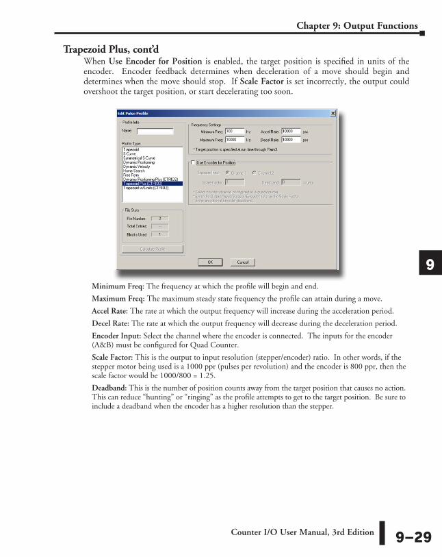
Trapezoid Plus, cont’d When Use Encoder for Position is enabled, the target position is specified in units of the encoder. Encoder feedback determines when deceleration of a move should begin and determines when the move should stop. If Scale Factor is set incorrectly, the output could overshoot the target position, or start decelerating too soon.
Minimum Freq: The frequency at which the profile will begin and end.
Maximum Freq: The maximum steady state frequency the profile can attain during a move.
Accel Rate: The rate at which the output frequency will increase during the acceleration period.
Decel Rate: The rate at which the output frequency will decrease during the deceleration period.
Encoder Input: Select the channel where the encoder is connected. The inputs for the encoder (A&B) must be configured for Quad Counter.
Scale Factor: This is the output to input resolution (stepper/encoder) ratio. In other words, if the stepper motor being used is a 1000 ppr (pulses per revolution) and the encoder is 800 ppr, then the scale factor would be 1000/800 = 1.25.
Deadband: This is the number of position counts away from the target position that causes no action. This can reduce “hunting” or “ringing” as the profile attempts to get to the target position. Be sure to include a deadband when the encoder has a higher resolution than the stepper.
Counter I/O User Manual, 3rd Edition 9–29
Chapter 9: Output Functions
1
2
3
4
5
6
7
8
9
10
11
12
13
14
A
B
C
D
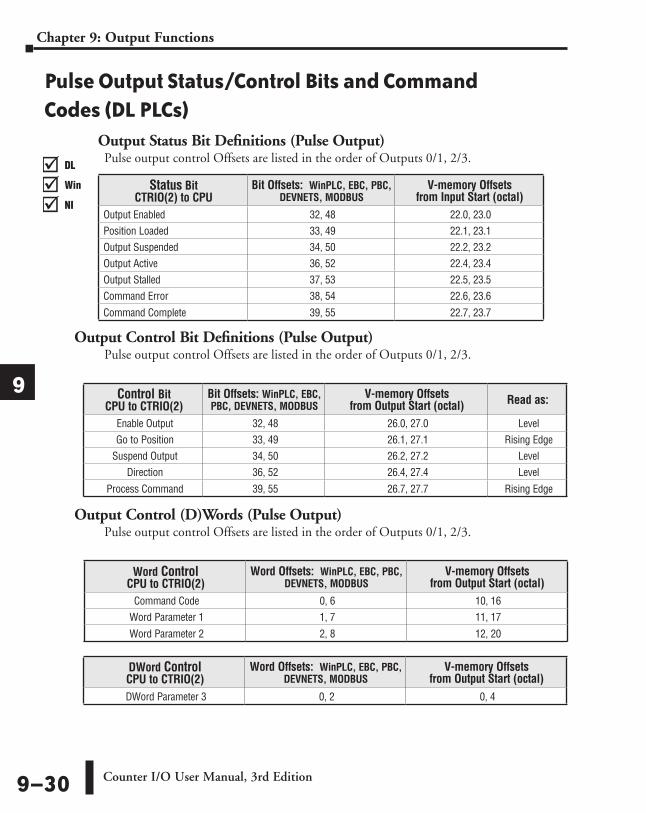
Pulse Output Status/Control Bits and Command Codes (DL PLCs)
Output Status Bit Definitions (Pulse Output)Pulse output control Offsets are listed in the order of Outputs 0/1, 2/3.
Output Control Bit Definitions (Pulse Output)Pulse output control Offsets are listed in the order of Outputs 0/1, 2/3.
Output Control (D)Words (Pulse Output)Pulse output control Offsets are listed in the order of Outputs 0/1, 2/3.
Word Control CPU to CTRIO(2)
Word Offsets: WinPLC, EBC, PBC, DEVNETS, MODBUS
V-memory Offsets from Output Start (octal)
Command Code 0, 6 10, 16Word Parameter 1 1, 7 11, 17
Word Parameter 2 2, 8 12, 20
DWord Control CPU to CTRIO(2)
Word Offsets: WinPLC, EBC, PBC, DEVNETS, MODBUS
V-memory Offsets from Output Start (octal)
DWord Parameter 3 0, 2 0, 4
Control Bit CPU to CTRIO(2)
Bit Offsets: WinPLC, EBC, PBC, DEVNETS, MODBUS
V-memory Offsets from Output Start (octal) Read as:
Enable Output 32, 48 26.0, 27.0 LevelGo to Position 33, 49 26.1, 27.1 Rising Edge
Suspend Output 34, 50 26.2, 27.2 Level Direction 36, 52 26.4, 27.4 Level
Process Command 39, 55 26.7, 27.7 Rising Edge
Status Bit CTRIO(2) to CPU
Bit Offsets: WinPLC, EBC, PBC, DEVNETS, MODBUS
V-memory Offsets from Input Start (octal)
Output Enabled 32, 48 22.0, 23.0Position Loaded 33, 49 22.1, 23.1Output Suspended 34, 50 22.2, 23.2Output Active 36, 52 22.4, 23.4Output Stalled 37, 53 22.5, 23.5Command Error 38, 54 22.6, 23.6
Command Complete 39, 55 22.7, 23.7
DL
Win
NI
���
DL
Win
NI
���
DL
Win
NI
���
DL
Win
NI
���
Counter I/O User Manual, 3rd Edition9–30
Chapter 9: Output Functions
1
2
3
4
5
6
7
8
9
10
11
12
13
14
A
B
C
D
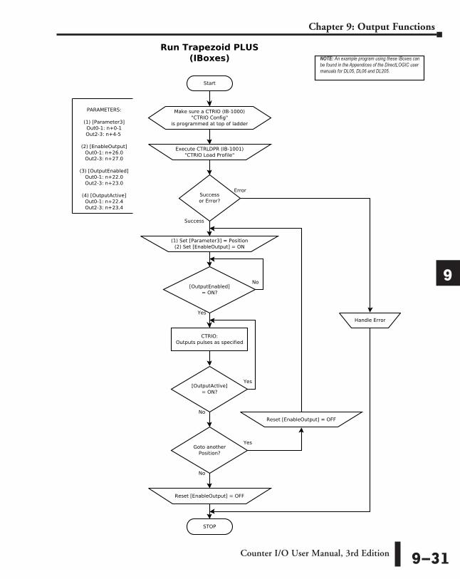
Start
Run Trapezoid PLUS(IBoxes)
Error
Success
PARAMETERS:
(1) [Parameter3]Out0-1: n+0-1Out2-3: n+4-5
(2) [EnableOutput]Out0-1: n+26.0Out2-3: n+27.0
(3) [OutputEnabled]Out0-1: n+22.0Out2-3: n+23.0
(4) [OutputActive]Out0-1: n+22.4Out2-3: n+23.4
Execute CTRLDPR (IB-1001)"CTRIO Load Profile"
Successor Error?
(1) Set [Parameter3] = Position(2) Set [EnableOutput] = ON
STOP
Handle Error
Make sure a CTRIO (IB-1000)"CTRIO Config"
is programmed at top of ladder
CTRIO:Outputs pulses as specified
[OutputEnabled]= ON?
No
Yes
[OutputActive]= ON?
Reset [EnableOutput] = OFF
No
Yes
Goto anotherPosition?
Reset [EnableOutput] = OFF
Yes
No
NOTE: An example program using these IBoxes can be found in the Appendices of the DirectLOGIC user manuals for DL05, DL06 and DL205.
Counter I/O User Manual, 3rd Edition 9–31
Chapter 9: Output Functions
1
2
3
4
5
6
7
8
9
10
11
12
13
14
A
B
C
D
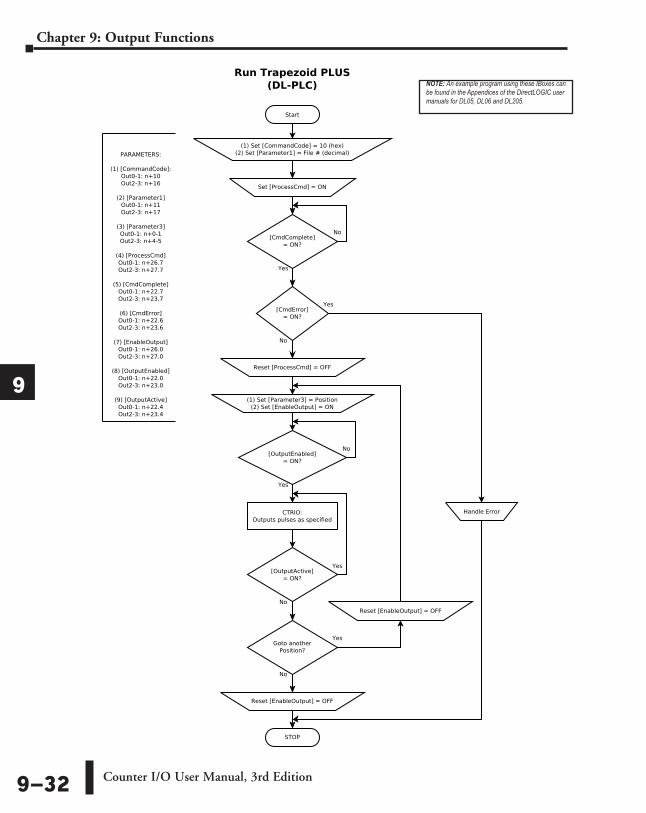
Start
Run Trapezoid PLUS(DL-PLC)
Yes
No
[CmdComplete]= ON?
Yes
No
PARAMETERS:
(1) [CommandCode]:Out0-1: n+10Out2-3: n+16
(2) [Parameter1]Out0-1: n+11Out2-3: n+17
(3) [Parameter3]Out0-1: n+0-1Out2-3: n+4-5
(4) [ProcessCmd]Out0-1: n+26.7Out2-3: n+27.7
(5) [CmdComplete]Out0-1: n+22.7Out2-3: n+23.7
(6) [CmdError]Out0-1: n+22.6Out2-3: n+23.6
(7) [EnableOutput]Out0-1: n+26.0Out2-3: n+27.0
(8) [OutputEnabled]Out0-1: n+22.0Out2-3: n+23.0
(9) [OutputActive]Out0-1: n+22.4Out2-3: n+23.4
CTRIO:Outputs pulses as specified
(1) Set [CommandCode] = 10 (hex)(2) Set [Parameter1] = File # (decimal)
[CmdError]= ON?
(1) Set [Parameter3] = Position(2) Set [EnableOutput] = ON
STOP
Handle Error
[OutputEnabled]= ON?
No
Yes
[OutputActive]= ON?
Reset [EnableOutput] = OFF
No
Yes
Set [ProcessCmd] = ON
Goto anotherPosition?
Reset [EnableOutput] = OFF
Reset [ProcessCmd] = OFF
Yes
No
NOTE: An example program using these IBoxes can be found in the Appendices of the DirectLOGIC user manuals for DL05, DL06 and DL205.
Counter I/O User Manual, 3rd Edition9–32
Chapter 9: Output Functions
1
2
3
4
5
6
7
8
9
10
11
12
13
14
A
B
C
D
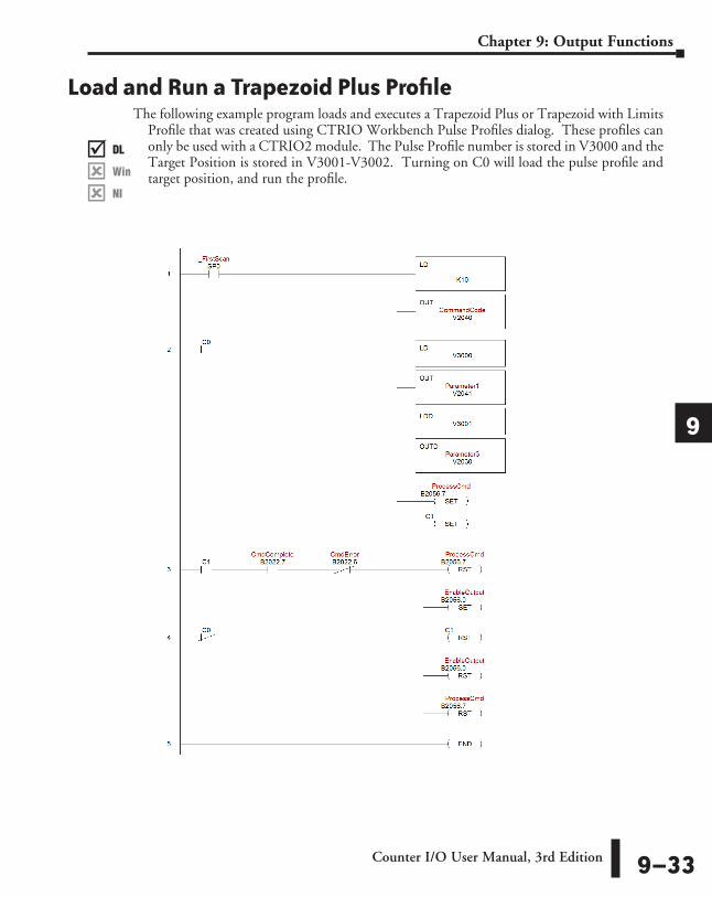
Load and Run a Trapezoid Plus Profile The following example program loads and executes a Trapezoid Plus or Trapezoid with Limits
Profile that was created using CTRIO Workbench Pulse Profiles dialog. These profiles can only be used with a CTRIO2 module. The Pulse Profile number is stored in V3000 and the Target Position is stored in V3001-V3002. Turning on C0 will load the pulse profile and target position, and run the profile.
DL
Win
NI
���
DL
Win
NI
���
DL
Win
NI
���
DL
Win
NI
���
Counter I/O User Manual, 3rd Edition 9–33
Chapter 9: Output Functions
1
2
3
4
5
6
7
8
9
10
11
12
13
14
A
B
C
D
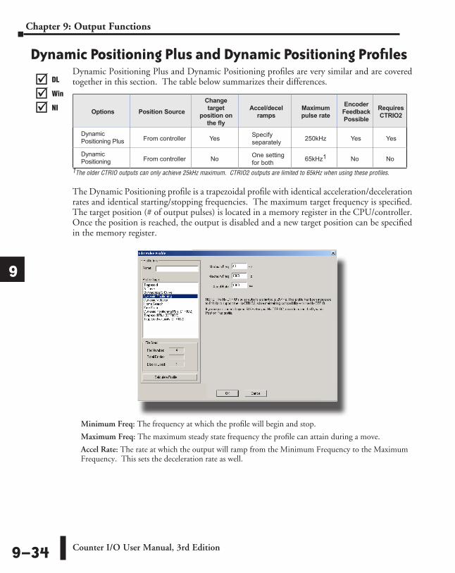
Dynamic Positioning Plus and Dynamic Positioning ProfilesDynamic Positioning Plus and Dynamic Positioning profiles are very similar and are covered together in this section. The table below summarizes their differences.
1The older CTRIO outputs can only achieve 25kHz maximum. CTRIO2 outputs are limited to 65kHz when using these profiles.
The Dynamic Positioning profile is a trapezoidal profile with identical acceleration/deceleration rates and identical starting/stopping frequencies. The maximum target frequency is specified. The target position (# of output pulses) is located in a memory register in the CPU/controller. Once the position is reached, the output is disabled and a new target position can be specified in the memory register.
Minimum Freq: The frequency at which the profile will begin and stop.
Maximum Freq: The maximum steady state frequency the profile can attain during a move.
Accel Rate: The rate at which the output will ramp from the Minimum Frequency to the Maximum Frequency. This sets the deceleration rate as well.
DL
Win
NI
���
DL
Win
NI
���
DL
Win
NI
���
DL
Win
NI
���
Options Position Source
Change target
position on the fly
Accel/decel ramps
Maximum pulse rate
Encoder Feedback Possible
Requires CTRIO2
Dynamic Positioning Plus From controller Yes Specify
separately 250kHz Yes Yes
Dynamic Positioning From controller No One setting
for both 65kHz1 No No
Counter I/O User Manual, 3rd Edition9–34
Chapter 9: Output Functions
1
2
3
4
5
6
7
8
9
10
11
12
13
14
A
B
C
D
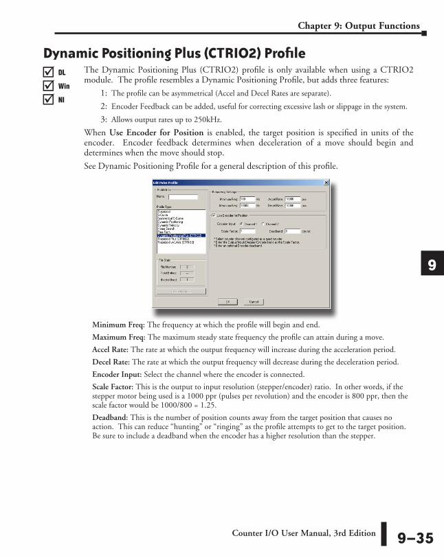
Dynamic Positioning Plus (CTRIO2) ProfileThe Dynamic Positioning Plus (CTRIO2) profile is only available when using a CTRIO2 module. The profile resembles a Dynamic Positioning Profile, but adds three features:
1: The profile can be asymmetrical (Accel and Decel Rates are separate).
2: Encoder Feedback can be added, useful for correcting excessive lash or slippage in the system.
3: Allows output rates up to 250kHz.
When Use Encoder for Position is enabled, the target position is specified in units of the encoder. Encoder feedback determines when deceleration of a move should begin and determines when the move should stop.
See Dynamic Positioning Profile for a general description of this profile.
Minimum Freq: The frequency at which the profile will begin and end.
Maximum Freq: The maximum steady state frequency the profile can attain during a move.
Accel Rate: The rate at which the output frequency will increase during the acceleration period.
Decel Rate: The rate at which the output frequency will decrease during the deceleration period.
Encoder Input: Select the channel where the encoder is connected.
Scale Factor: This is the output to input resolution (stepper/encoder) ratio. In other words, if the stepper motor being used is a 1000 ppr (pulses per revolution) and the encoder is 800 ppr, then the scale factor would be 1000/800 = 1.25.
Deadband: This is the number of position counts away from the target position that causes no action. This can reduce “hunting” or “ringing” as the profile attempts to get to the target position. Be sure to include a deadband when the encoder has a higher resolution than the stepper.
DL
Win
NI
���
DL
Win
NI
���
DL
Win
NI
���
DL
Win
NI
���
Counter I/O User Manual, 3rd Edition 9–35
Chapter 9: Output Functions
1
2
3
4
5
6
7
8
9
10
11
12
13
14
A
B
C
D

Pulse Output Status/Control Bits and Command Codes (DL PLCs)
Output Status Bit Definitions (Pulse Output)Pulse output control Offsets are listed in the order of Outputs 0/1, 2/3.
Output Control Bit Definitions (Pulse Output)Pulse output control Offsets are listed in the order of Outputs 0/1, 2/3.
Output Control (D)Words (Pulse Output)Pulse output control Offsets are listed in the order of Outputs 0/1, 2/3.
Word Control CPU to CTRIO(2)
Word Offsets: WinPLC, EBC, PBC, DEVNETS, MODBUS
V-memory Offsets from Output Start (octal)
Command Code 0, 6 10, 16Word Parameter 1 1, 7 11, 17
Word Parameter 2 2, 8 12, 20
DL
Win
NI
���
DL
Win
NI
���
DL
Win
NI
���
DL
Win
NI
���
DWord Control CPU to CTRIO(2)
Word Offsets: WinPLC, EBC, PBC, DEVNETS, MODBUS
V-memory Offsets from Output Start (octal)
DWord Parameter 3 0, 2 0, 4
Control Bit CPU to CTRIO(2)
Bit Offsets: WinPLC, EBC, PBC, DEVNETS, MODBUS
V-memory Offsets from Output Start (octal) Read as:
Enable Output 32, 48 26.0, 27.0 LevelGo to Position 33, 49 26.1, 27.1 Rising Edge
Suspend Output 34, 50 26.2, 27.2 Level Direction 36, 52 26.4, 27.4 Level
Process Command 39, 55 26.7, 27.7 Rising Edge
Status Bit CTRIO(2) to CPU
Bit Offsets: WinPLC, EBC, PBC, DEVNETS, MODBUS
V-memory Offsets from Input Start (octal)
Output Enabled 32, 48 22.0, 23.0Position Loaded 33, 49 22.1, 23.1Output Suspended 34, 50 22.2, 23.2Output Active 36, 52 22.4, 23.4Output Stalled 37, 53 22.5, 23.5Command Error 38, 54 22.6, 23.6
Command Complete 39, 55 22.7, 23.7
Counter I/O User Manual, 3rd Edition9–36
Chapter 9: Output Functions
1
2
3
4
5
6
7
8
9
10
11
12
13
14
A
B
C
D

Dynamic Positioning/Dynamic Positioning Plus, (cont’d) For Dynamic Positioning/Positioning Plus only, the motion limits of Min Frequency, Max Frequency, and Acceleration rate come from the CTRIO Workbench Profile. After loading a Dynamic Positioning/Positioning Plus Profile, setting the Enable Output causes the CTRIO(2) module to assume a position of 0 pulses. The program should write the target position in DWord Parameter 3, and set the Go to Position bit. This will cause the CTRIO(2) module to set both Pulses Active and the New Position Loaded bit, then begin to output pulses. The number of pulses and direction are determined by the CTRIO(2) module based on the difference between the current location and the specified target location.
The program can monitor the state of the Pulses Active bit and the New Position Loaded bit to
determine when the new position has been attained. The New Position Loaded status bit will always follow the state of the Load/Seek New Position control bit. This status bit should be used to signal the program that the CTRIO(2) module has received the new state of the control bit. You do not have to wait on the CTRIO(2) module to complete a move that is in progress before loading the next target location. After the GoTo Position is acknowledged, the program can load the next position into the DWord Parameter 3. When Pulses Active Status goes to 0, then setting the GoTo Position control bit will again start the output toward the new position. The CTRIO(2) module moves to the new position relative to its previous position as long as the Enable Output control bit remains set. Clearing the Enable Output bit will disable output pulsing and reset the current position to 0.The following pages show a DirectLOGIC programming example that executes a Dynamic Positioning/Positioning Plus pulse profile using the bit/(D)word addressing in the table on page 9-38.
The sign of the value in the Target Position register (Parameter 3) determines the direction of the pulse train output. In the DirectLOGIC programming example to the right, BCD 5000 is converted to decimal -5000 when C0 is turned ON. You could load (LD) a V memory location instead of using a constant as shown in the example.
Position Loaded Status Bit V40622.1 or C441
Pulses Active Status Bit V40622.0 or C440 CTRIO(2) Pulse Output State
0 0 Idle1 1 Go To Position Acknowledged, Pulsing0 1 Still Pulsing, Go To Position Control Bit is OFF
1 0 Go To Position Acknowledged, Position Attained
C0K5000
LDD
BIN
1
INV
K1ADDD
DirectSOFT
V3000OUTD
DL
Win
NI
���
DL
Win
NI
���
DL
Win
NI
���
DL
Win
NI
���
Counter I/O User Manual, 3rd Edition 9–37
Chapter 9: Output Functions
1
2
3
4
5
6
7
8
9
10
11
12
13
14
A
B
C
D
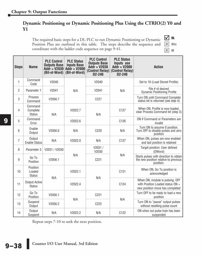
Dynamic Positioning or Dynamic Positioning Plus Using the CTRIO(2) Y0 and Y1
The required basic steps for a DL-PLC to run Dynamic Positioning or Dynamic Position Plus are outlined in this table. The steps describe the sequence and coordinate with the ladder code sequence on page 9-41.
Repeat steps 7-10 to seek the next position.
Steps NamePLC Control
Outputs Base Addr = V2030 (Bit-of-Word)
PLC Status Inputs Base
Addr = V2000 (Bit-of-Word)
PLC Control Outputs Base Addr = V2030
(Control Relay) D2-240
PLC Status Inputs ase
Addr = V2000 (Control Relay)
D2-240
Action
1 Command Code V2040
N/A
V2040
N/A
Set to 10 (Load Stored Profile)
2 Parameter 1 V2041 V2041 File # of desired Dynamic Positioning Profile
3 Process Command V2056.7 C227 Turn ON until Command Complete
status bit is returned (see step 4)
4Command Complete
Status N/AV2022.7
N/AC127 When ON, Profile is now loaded,
clear Process Command bit (step 3)
5 Command Error V2022.6 C126 ON if Command or Parameters are
invalid
6 Enable Output V2056.0 N/A C220 N/A
Turn ON to assume 0 position, Turn OFF to disable pulses and zero
position
7 Output Enable Status N/A V2022.0 N/A C127 When ON, pulses are now enabled
and last position is retained
8 Parameter 3 V2031 / V2030
N/A
V2031 / V2030
N/A
Target position: User defined (DWord)
9 Go To Position V2056.1 C221
Starts pulses with direction to obtain the new position relative to previous
position.
10Position Loaded Status
N/A
V2022.1
N/A
C121 When ON, Go To position is acknowledged
11 Output Active Status V2022.4 C124
When ON, module is pulsing, OFF with Position Loaded status ON = new position move has completed
12 Go To Position V2056.1
N/AC221
N/A
Turn OFF to be ready to load a new position
13 Suspend Output V2056.2 C222 Turn ON to “pause” output pulses
without resetting pulse count
14 Output Suspend N/A V2022.2 N/A C122 ON when out pulse train has been
suspended
DL
Win
NI
���
DL
Win
NI
���
DL
Win
NI
���
DL
Win
NI
���
Counter I/O User Manual, 3rd Edition9–38
Chapter 9: Output Functions
1
2
3
4
5
6
7
8
9
10
11
12
13
14
A
B
C
D
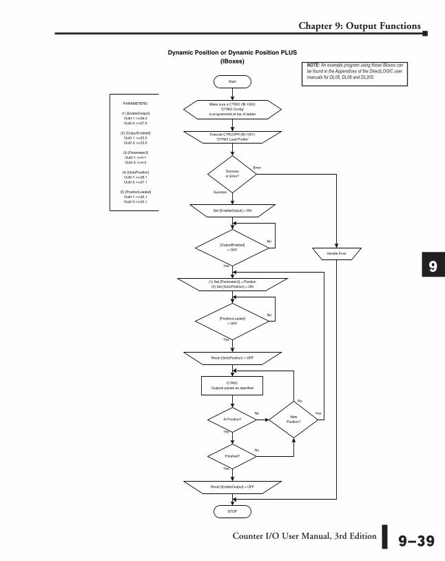
Start
Dynamic Position or Dynamic Position PLUS(IBoxes)
Error
Success
PARAMETERS:
(1) [EnableOutput]Out0-1: n+26.0Out2-3: n+27.0
(2) [OutputEnabled]Out0-1: n+22.0Out2-3: n+23.0
(3) [Parameter3]Out0-1: n+0-1Out2-3: n+4-5
(4) [GotoPosition]Out0-1: n+26.1Out2-3: n+27.1
(5) [PositionLoaded]Out0-1: n+22.1Out2-3: n+23.1
Execute CTRLDPR (IB-1001)"CTRIO Load Profile"
Successor Error?
Handle Error
CTRIO:Outputs pulses as specified
Set [EnableOutput] = ON
STOP
[OutputEnabled]= ON?
No
Yes
At Position?
Reset [EnableOutput] = OFF
No
Yes
NewPosition?
Yes
No
(1) Set [Parameter3] = Position(2) Set [GotoPosition] = ON
[PositionLoaded]= ON?
No
Reset [GotoPosition] = OFF
Yes
Finished?
No
Yes
Make sure a CTRIO (IB-1000)"CTRIO Config"
is programmed at top of ladder
NOTE: An example program using these IBoxes can be found in the Appendices of the DirectLOGIC user manuals for DL05, DL06 and DL205.
Counter I/O User Manual, 3rd Edition 9–39
Chapter 9: Output Functions
1
2
3
4
5
6
7
8
9
10
11
12
13
14
A
B
C
D
Start
Dynamic Position or Dynamic Position PLUS(DL-PLC)
Yes
No
[CmdComplete]= ON?
Yes
No
PARAMETERS:
(1) [CommandCode]:Out0-1: n+10Out2-3: n+16
(2) [Parameter1]Out0-1: n+11Out2-3: n+17
(3) [ProcessCmd]Out0-1: n+26.7Out2-3: n+27.7
(4) [CmdComplete]Out0-1: n+22.7Out2-3: n+23.7
(5) [CmdError]Out0-1: n+22.6Out2-3: n+23.6
(6) [EnableOutput]Out0-1: n+26.0Out2-3: n+27.0
(7) [Outputenabled]Out0-1: n+22.0Out2-3: n+23.0
(8) [Parameter3]Out0-1: n+0-1Out2-3: n+4-5
(9) [GotoPosition]Out0-1: n+26.1Out2-3: n+27.1
(10) [PositionLoaded]Out0-1: n+22.1Out2-3: n+23.1
CTRIO:Outputs pulses as specified
(1) Set [CommandCode] = 10 (hex)(2) Set [Parameter1] = File # (decimal)
(3) Set [ProcessCmd] = ON
[CmdError]= ON?
(1) Reset [ProcessCmd] = OFF(2) Set [EnableOutput] = ON
STOP
Handle Error
[OutputEnabled]= ON?
No
Yes
At Position?
Reset [EnableOutput] = OFF
No
Yes
NewPosition?
Yes
No
(1) Set [Parameter3] = Position(2) Set [GotoPosition] = ON
[PositionLoaded]= ON?
No
Reset [GotoPosition] = OFF
Yes
Finished?
No
Yes
NOTE: An example program using these IBoxes can be found in the Appendices of the DirectLOGIC user manuals for DL05, DL06 and DL205.
Counter I/O User Manual, 3rd Edition9–40
Chapter 9: Output Functions
1
2
3
4
5
6
7
8
9
10
11
12
13
14
A
B
C
D
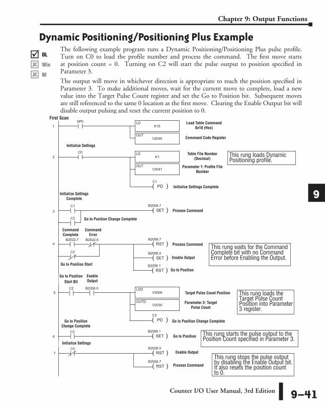
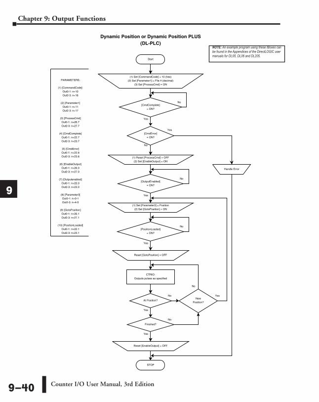
Dynamic Positioning/Positioning Plus ExampleThe following example program runs a Dynamic Positioning/Positioning Plus pulse profile. Turn on C0 to load the profile number and process the command. The first move starts at position count = 0. Turning on C2 will start the pulse output to position specified in Parameter 3.
The output will move in whichever direction is appropriate to reach the position specified in Parameter 3. To make additional moves, wait for the current move to complete, load a new value into the Target Pulse Count register and set the Go to Position bit. Subsequent moves are still referenced to the same 0 location as the first move. Clearing the Enable Output bit will disable output pulsing and reset the current position to 0.
SP0
K10LD
V2040OUT
1
2
( )PD
C1
( )SET
B2056.7
C0
( )RST
B2056.0
( )RST
B2056.7
C0
K1LD
V2041OUT
( )END
6
DirectSOFT 32
3
4
V3000LDD
V2030OUTD
5
B2056.0
C1
7
C3
B2022.7 B2022.6
( )RST
B2056.7
( )SET
B2056.0C2
( )RST
B2056.1
( )PD
C3
( )SET
B2056.1C3
8
C2
First ScanLoad Table Command
0x10 (Hex)
Command Code Register
Table File Number (Decimal)
Parameter 1: Profile File Number
Process Command
Enable Output
Go to Position Start Bit
Command Complete
Command Error
Initialize Settings
Go to Position Start
Target Pulse Count Position
Parameter 3: Target Pulse Count
Go to Position
Go to Position Change Complete
Process Command
Initialize Settings Complete
This rung waits for the Command Complete bit with no Command Error before Enabling the Output.
This rung loads Dynamic Positioning profile.
This rung loads the Target Pulse Count Position into Parameter 3 register.
Initialize Settings Complete
Enable Output
Initialize Settings
Enable Output
This rung starts the pulse output to the Position Count specified in Parameter 3.
This rung stops the pulse output by disabling the Enable Output bit. It also resets the position count to 0.
Go to Position Change CompleteGo to Position Change Complete
Go to Position
Process Command
DL
Win
NI
���
DL
Win
NI
���
DL
Win
NI
���
DL
Win
NI
���
Counter I/O User Manual, 3rd Edition 9–41
Chapter 9: Output Functions
1
2
3
4
5
6
7
8
9
10
11
12
13
14
A
B
C
D
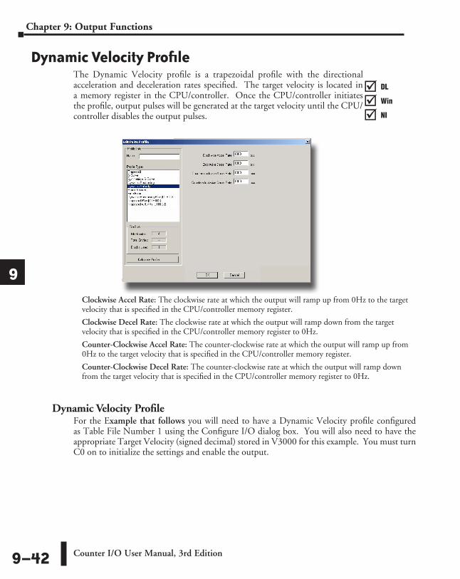
Dynamic Velocity ProfileThe Dynamic Velocity profile is a trapezoidal profile with the directional acceleration and deceleration rates specified. The target velocity is located in a memory register in the CPU/controller. Once the CPU/controller initiates the profile, output pulses will be generated at the target velocity until the CPU/controller disables the output pulses.
Clockwise Accel Rate: The clockwise rate at which the output will ramp up from 0Hz to the target velocity that is specified in the CPU/controller memory register.
Clockwise Decel Rate: The clockwise rate at which the output will ramp down from the target velocity that is specified in the CPU/controller memory register to 0Hz.
Counter-Clockwise Accel Rate: The counter-clockwise rate at which the output will ramp up from 0Hz to the target velocity that is specified in the CPU/controller memory register.
Counter-Clockwise Decel Rate: The counter-clockwise rate at which the output will ramp down from the target velocity that is specified in the CPU/controller memory register to 0Hz.
Dynamic Velocity ProfileFor the Example that follows you will need to have a Dynamic Velocity profile configured as Table File Number 1 using the Configure I/O dialog box. You will also need to have the appropriate Target Velocity (signed decimal) stored in V3000 for this example. You must turn C0 on to initialize the settings and enable the output.
DL
Win
NI
���
DL
Win
NI
���
DL
Win
NI
���
DL
Win
NI
���
Counter I/O User Manual, 3rd Edition9–42
Chapter 9: Output Functions
1
2
3
4
5
6
7
8
9
10
11
12
13
14
A
B
C
D
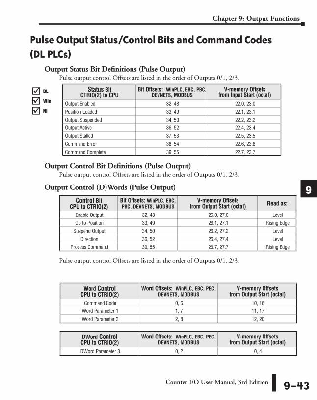
Pulse Output Status/Control Bits and Command Codes (DL PLCs)
Output Status Bit Definitions (Pulse Output)Pulse output control Offsets are listed in the order of Outputs 0/1, 2/3.
Output Control Bit Definitions (Pulse Output)Pulse output control Offsets are listed in the order of Outputs 0/1, 2/3.
Output Control (D)Words (Pulse Output)
Pulse output control Offsets are listed in the order of Outputs 0/1, 2/3.
Word Control CPU to CTRIO(2)
Word Offsets: WinPLC, EBC, PBC, DEVNETS, MODBUS
V-memory Offsets from Output Start (octal)
Command Code 0, 6 10, 16Word Parameter 1 1, 7 11, 17
Word Parameter 2 2, 8 12, 20
DWord Control CPU to CTRIO(2)
Word Offsets: WinPLC, EBC, PBC, DEVNETS, MODBUS
V-memory Offsets from Output Start (octal)
DWord Parameter 3 0, 2 0, 4
Control Bit CPU to CTRIO(2)
Bit Offsets: WinPLC, EBC, PBC, DEVNETS, MODBUS
V-memory Offsets from Output Start (octal) Read as:
Enable Output 32, 48 26.0, 27.0 LevelGo to Position 33, 49 26.1, 27.1 Rising Edge
Suspend Output 34, 50 26.2, 27.2 Level Direction 36, 52 26.4, 27.4 Level
Process Command 39, 55 26.7, 27.7 Rising Edge
DL
Win
NI
���
DL
Win
NI
���
DL
Win
NI
���
DL
Win
NI
���
Status Bit CTRIO(2) to CPU
Bit Offsets: WinPLC, EBC, PBC, DEVNETS, MODBUS
V-memory Offsets from Input Start (octal)
Output Enabled 32, 48 22.0, 23.0Position Loaded 33, 49 22.1, 23.1Output Suspended 34, 50 22.2, 23.2Output Active 36, 52 22.4, 23.4Output Stalled 37, 53 22.5, 23.5Command Error 38, 54 22.6, 23.6
Command Complete 39, 55 22.7, 23.7
Counter I/O User Manual, 3rd Edition 9–43
Chapter 9: Output Functions
1
2
3
4
5
6
7
8
9
10
11
12
13
14
A
B
C
D
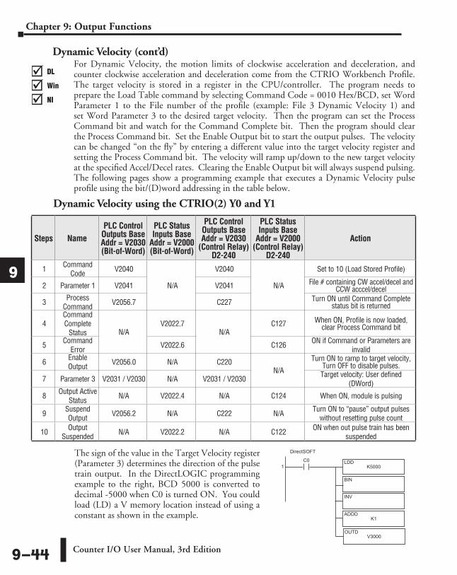
Dynamic Velocity (cont’d)For Dynamic Velocity, the motion limits of clockwise acceleration and deceleration, and counter clockwise acceleration and deceleration come from the CTRIO Workbench Profile. The target velocity is stored in a register in the CPU/controller. The program needs to prepare the Load Table command by selecting Command Code = 0010 Hex/BCD, set Word Parameter 1 to the File number of the profile (example: File 3 Dynamic Velocity 1) and set Word Parameter 3 to the desired target velocity. Then the program can set the Process Command bit and watch for the Command Complete bit. Then the program should clear the Process Command bit. Set the Enable Output bit to start the output pulses. The velocity can be changed “on the fly” by entering a different value into the target velocity register and setting the Process Command bit. The velocity will ramp up/down to the new target velocity at the specified Accel/Decel rates. Clearing the Enable Output bit will always suspend pulsing. The following pages show a programming example that executes a Dynamic Velocity pulse profile using the bit/(D)word addressing in the table below.
Dynamic Velocity using the CTRIO(2) Y0 and Y1
The sign of the value in the Target Velocity register (Parameter 3) determines the direction of the pulse train output. In the DirectLOGIC programming example to the right, BCD 5000 is converted to decimal -5000 when C0 is turned ON. You could load (LD) a V memory location instead of using a constant as shown in the example.
Steps NamePLC Control
Outputs Base Addr = V2030 (Bit-of-Word)
PLC Status Inputs Base
Addr = V2000 (Bit-of-Word)
PLC Control Outputs Base Addr = V2030
(Control Relay) D2-240
PLC Status Inputs Base
Addr = V2000 (Control Relay)
D2-240
Action
1 Command Code V2040
N/A
V2040
N/A
Set to 10 (Load Stored Profile)
2 Parameter 1 V2041 V2041 File # containing CW accel/decel and CCW acccel/decel
3 Process Command V2056.7 C227 Turn ON until Command Complete
status bit is returned
4Command Complete
Status N/AV2022.7
N/AC127 When ON, Profile is now loaded,
clear Process Command bit
5 Command Error V2022.6 C126 ON if Command or Parameters are
invalid
6 Enable Output V2056.0 N/A C220
N/A
Turn ON to ramp to target velocity, Turn OFF to disable pulses.
7 Parameter 3 V2031 / V2030 N/A V2031 / V2030 Target velocity: User defined (DWord)
8 Output Active Status N/A V2022.4 N/A C124 When ON, module is pulsing
9 Suspend Output V2056.2 N/A C222 N/A Turn ON to “pause” output pulses
without resetting pulse count
10 Output Suspended N/A V2022.2 N/A C122 ON when out pulse train has been
suspended
DL
Win
NI
���
DL
Win
NI
���
DL
Win
NI
���
DL
Win
NI
���
C0K5000
LDD
BIN
1
INV
K1ADDD
DirectSOFT
V3000OUTD
Counter I/O User Manual, 3rd Edition9–44
Chapter 9: Output Functions
1
2
3
4
5
6
7
8
9
10
11
12
13
14
A
B
C
D
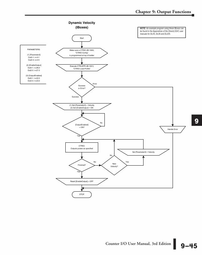
Start
Dynamic Velocity(IBoxes)
Error
Success
PARAMETERS:
(1) [Parameter3]Out0-1: n+0-1Out2-3: n+4-5
(2) [EnableOutput]Out0-1: n+26.0Out2-3: n+27.0
(3) [OutputEnabled]Out0-1: n+22.0Out2-3: n+23.0
Execute CTRLDPR (IB-1001)"CTRIO Load Profile"
Successor Error?
(1) Set [Parameter3] = Velocity(2) Set [EnableOutput] = ON
STOP
Handle Error
[OutputEnabled]= ON?
No
Yes
Reset [EnableOutput] = OFF
CTRIO:Outputs pulses as specified
Finished?
No
Yes
NewVelocity?
Set [Parameter3] = Velocity
Yes
No
Make sure a CTRIO (IB-1000)"CTRIO Config"
is programmed at top of ladder
NOTE: An example program using these IBoxes can be found in the Appendices of the DirectLOGIC user manuals for DL05, DL06 and DL205.
Counter I/O User Manual, 3rd Edition 9–45
Chapter 9: Output Functions
1
2
3
4
5
6
7
8
9
10
11
12
13
14
A
B
C
D
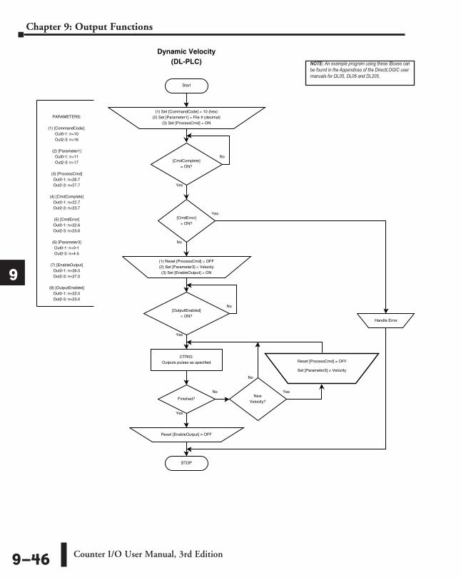
Start
Dynamic Velocity(DL-PLC)
Yes
No
[CmdComplete]= ON?
Yes
No
PARAMETERS:
(1) [CommandCode]:Out0-1: n+10Out2-3: n+16
(2) [Parameter1]Out0-1: n+11Out2-3: n+17
(3) [ProcessCmd]Out0-1: n+26.7Out2-3: n+27.7
(4) [CmdComplete]Out0-1: n+22.7Out2-3: n+23.7
(5) [CmdError]Out0-1: n+22.6Out2-3: n+23.6
(6) [Parameter3]Out0-1: n+0-1Out2-3: n+4-5
(7) [EnableOutput]Out0-1: n+26.0Out2-3: n+27.0
(8) [OutputEnabled]Out0-1: n+22.0Out2-3: n+23.0
CTRIO:Outputs pulses as specified
(1) Set [CommandCode] = 10 (hex)(2) Set [Parameter1] = File # (decimal)
(3) Set [ProcessCmd] = ON
[CmdError]= ON?
(1) Reset [ProcessCmd] = OFF(2) Set [Parameter3] = Velocity(3) Set [EnableOutput] = ON
STOP
Handle Error
[OutputEnabled]= ON?
No
Yes
Finished?
Reset [EnableOutput] = OFF
No
Yes
NewVelocity?
Set [Parameter3] = Velocity
Reset [ProcessCmd] = OFF
Yes
No
NOTE: An example program using these IBoxes can be found in the Appendices of the DirectLOGIC user manuals for DL05, DL06 and DL205.
Counter I/O User Manual, 3rd Edition9–46
Chapter 9: Output Functions
1
2
3
4
5
6
7
8
9
10
11
12
13
14
A
B
C
D
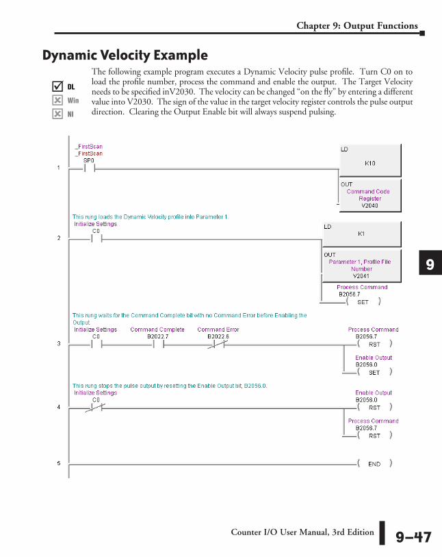
Dynamic Velocity ExampleThe following example program executes a Dynamic Velocity pulse profile. Turn C0 on to load the profile number, process the command and enable the output. The Target Velocity needs to be specified inV2030. The velocity can be changed “on the fly” by entering a different value into V2030. The sign of the value in the target velocity register controls the pulse output direction. Clearing the Output Enable bit will always suspend pulsing.
DL
Win
NI
���
DL
Win
NI
���
DL
Win
NI
���
DL
Win
NI
���
Counter I/O User Manual, 3rd Edition 9–47
Chapter 9: Output Functions
1
2
3
4
5
6
7
8
9
10
11
12
13
14
A
B
C
D
Velocity Mode Velocity Mode is used to set the output to a frequency and duty cycle.
NOTE: Velocity Mode controls the pulse outputs directly from the CPU/controller program. No CTRIO Workbench Pulse Profile is required for this mode.
Velocity Mode is not defined or created using the Pulse Profiles Table dialog in CTRIO Workbench. However, the output must be configured for Pulse (Step/Direction) or Pulse (CW/CCW) using the Configure IO dialog. The profile parameters are specified in CPU/controller memory registers. There are no acceleration ramps with Velocity Mode. The output will step directly to the specified frequency and to the specified duty cycle.
The user specifies the target frequency, pulse train duty cycle and the step count. Once initiated, the output will begin pulsing at the target frequency and continue until the step count is reached. There is no ramping to the target frequency. With a step count of 0xFFFFFFFF, the pulse output will continue indefinitely until the control program disables the output.
Velocity Mode command (Command = 0020 Hex/BCD) allows a specified number of pulse output counts or the number of Pulses can be set to “FFFFFFFF” in Hex for unlimited pulse counts. Leaving the Duty Cycle set to 0 achieves the default (50%), otherwise it can be set in 1% increments by writing this value from 1 to 99 decimal. After this command is processed, the Run Frequency and Duty Cycle fields can be adjusted by direct access. In order to change directions from Pulse Output in “Velocity” mode, the Enable Output bit must first be cleared (which stops the Pulse Outputs). Then after the new Direction bit is written, the Enable Output bit can be set to resume pulsing. Refer to the following table for a DirectLOGIC programming example that executes a Velocity Mode pulse profile using bit/(D)word addressing.
DL
Win
NI
���
DL
Win
NI
���
DL
Win
NI
���
DL
Win
NI
���
Counter I/O User Manual, 3rd Edition9–48
Chapter 9: Output Functions
1
2
3
4
5
6
7
8
9
10
11
12
13
14
A
B
C
D
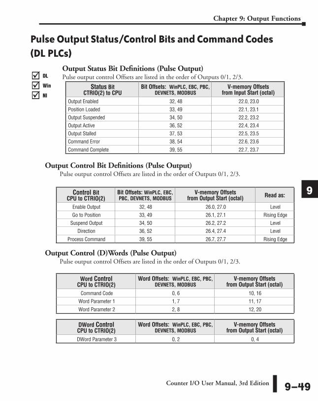
Pulse Output Status/Control Bits and Command Codes (DL PLCs)
Output Status Bit Definitions (Pulse Output)Pulse output control Offsets are listed in the order of Outputs 0/1, 2/3.
Output Control Bit Definitions (Pulse Output)Pulse output control Offsets are listed in the order of Outputs 0/1, 2/3.
Output Control (D)Words (Pulse Output)Pulse output control Offsets are listed in the order of Outputs 0/1, 2/3.
Word Control CPU to CTRIO(2)
Word Offsets: WinPLC, EBC, PBC, DEVNETS, MODBUS
V-memory Offsets from Output Start (octal)
Command Code 0, 6 10, 16Word Parameter 1 1, 7 11, 17
Word Parameter 2 2, 8 12, 20
DWord Control CPU to CTRIO(2)
Word Offsets: WinPLC, EBC, PBC, DEVNETS, MODBUS
V-memory Offsets from Output Start (octal)
DWord Parameter 3 0, 2 0, 4
Control Bit CPU to CTRIO(2)
Bit Offsets: WinPLC, EBC, PBC, DEVNETS, MODBUS
V-memory Offsets from Output Start (octal) Read as:
Enable Output 32, 48 26.0, 27.0 LevelGo to Position 33, 49 26.1, 27.1 Rising Edge
Suspend Output 34, 50 26.2, 27.2 Level Direction 36, 52 26.4, 27.4 Level
Process Command 39, 55 26.7, 27.7 Rising Edge
Status Bit CTRIO(2) to CPU
Bit Offsets: WinPLC, EBC, PBC, DEVNETS, MODBUS
V-memory Offsets from Input Start (octal)
Output Enabled 32, 48 22.0, 23.0Position Loaded 33, 49 22.1, 23.1Output Suspended 34, 50 22.2, 23.2Output Active 36, 52 22.4, 23.4Output Stalled 37, 53 22.5, 23.5Command Error 38, 54 22.6, 23.6
Command Complete 39, 55 22.7, 23.7
DL
Win
NI
���
DL
Win
NI
���
DL
Win
NI
���
DL
Win
NI
���
Counter I/O User Manual, 3rd Edition 9–49
Chapter 9: Output Functions
1
2
3
4
5
6
7
8
9
10
11
12
13
14
A
B
C
D
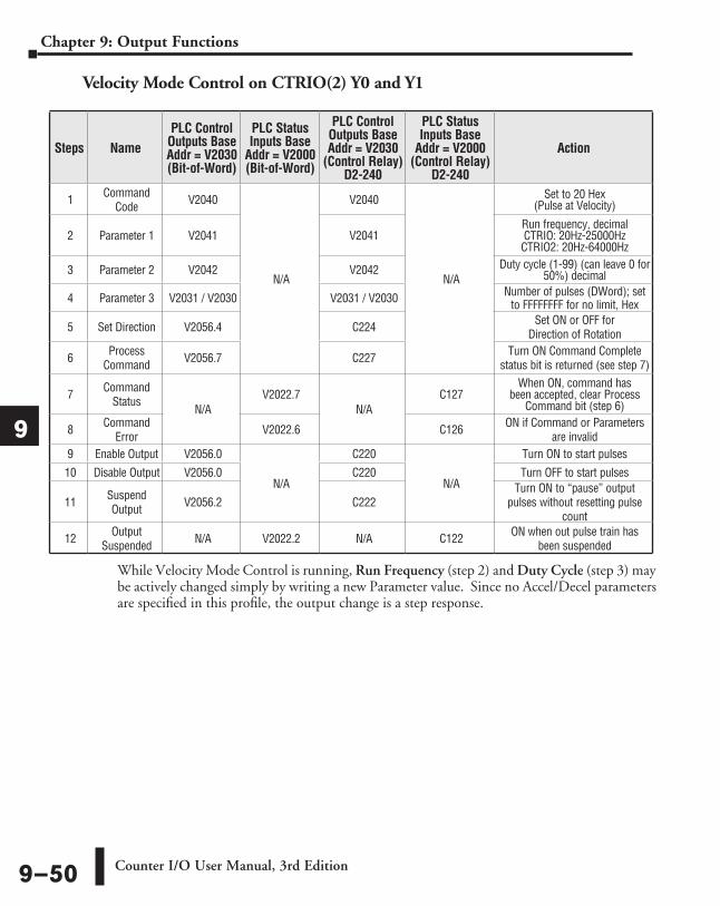
While Velocity Mode Control is running, Run Frequency (step 2) and Duty Cycle (step 3) may be actively changed simply by writing a new Parameter value. Since no Accel/Decel parameters are specified in this profile, the output change is a step response.
Steps NamePLC Control
Outputs Base Addr = V2030 (Bit-of-Word)
PLC Status Inputs Base
Addr = V2000 (Bit-of-Word)
PLC Control Outputs Base Addr = V2030
(Control Relay) D2-240
PLC Status Inputs Base
Addr = V2000 (Control Relay)
D2-240
Action
1 Command Code V2040
N/A
V2040
N/A
Set to 20 Hex (Pulse at Velocity)
2 Parameter 1 V2041 V2041Run frequency, decimal CTRIO: 20Hz-25000Hz CTRIO2: 20Hz-64000Hz
3 Parameter 2 V2042 V2042 Duty cycle (1-99) (can leave 0 for 50%) decimal
4 Parameter 3 V2031 / V2030 V2031 / V2030 Number of pulses (DWord); set to FFFFFFFF for no limit, Hex
5 Set Direction V2056.4 C224 Set ON or OFF for Direction of Rotation
6 Process Command V2056.7 C227 Turn ON Command Complete
status bit is returned (see step 7)
7 Command Status
N/AV2022.7
N/AC127
When ON, command has been accepted, clear Process
Command bit (step 6)
8 Command Error V2022.6 C126 ON if Command or Parameters
are invalid9 Enable Output V2056.0
N/A
C220
N/A
Turn ON to start pulses
10 Disable Output V2056.0 C220 Turn OFF to start pulses
11 Suspend Output V2056.2 C222
Turn ON to “pause” output pulses without resetting pulse
count
12 Output Suspended N/A V2022.2 N/A C122 ON when out pulse train has
been suspended
Velocity Mode Control on CTRIO(2) Y0 and Y1
Counter I/O User Manual, 3rd Edition9–50
Chapter 9: Output Functions
1
2
3
4
5
6
7
8
9
10
11
12
13
14
A
B
C
D
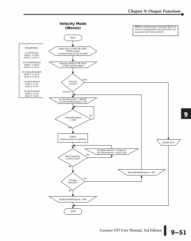
NOTE: An example program using these IBoxes can be found in the Appendices of the DirectLOGIC user manuals for DL05, DL06 and DL205.
Counter I/O User Manual, 3rd Edition 9–51
Chapter 9: Output Functions
1
2
3
4
5
6
7
8
9
10
11
12
13
14
A
B
C
D
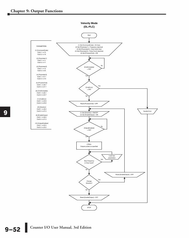
Start
Velocity Mode(DL-PLC)
Yes
No
[CmdComplete]= ON?
Yes
No
PARAMETERS:
(1) [CommandCode]:Out0-1: n+10Out2-3: n+16
(2) [Parameter1]Out0-1: n+11Out2-3: n+17
(3) [Parameter2]Out0-1: n+12Out2-3: n+20
(4) [Parameter3]Out0-1: n+0-1Out2-3: n+4-5
(5) [ProcessCmd]Out0-1: n+26.7Out2-3: n+27.7
(6) [CmdComplete]Out0-1: n+22.7Out2-3: n+23.7
(7) [CmdError]Out0-1: n+22.6Out2-3: n+23.6
(8) [Direction]Out0-1: n+26.4Out2-3: n+27.4
(9) [EnableOutput]Out0-1: n+26.0Out2-3: n+27.0
(10) [OutputEnabled]Out0-1: n+22.0Out2-3: n+23.0
CTRIO:Outputs pulses as specified
(1) Set [CommandCode] = 20 (hex)(2) Set [Parameter1] = Frequency (decimal)
(3) Set [Parameter2] = Duty Cycle (hex)(4) Set [Parameter3] = Pulse Count (decimal)
(5) Set [ProcessCmd] = ON
[CmdError]= ON?
Reset [ProcessCmd] = OFF
STOP
Handle Error
[OutputEnabled]= ON?
No
Yes
New Frequencyor Duty Cycle?
Load newparameters
Yes
No
ChangeDirection?
Reset [EnableOutput] = OFF
(1) Set [Direction] = ON/OFF(2) Set [EnableOutput] = ON
Reset [EnableOutput] = OFF
Yes
No
Counter I/O User Manual, 3rd Edition9–52
Chapter 9: Output Functions
1
2
3
4
5
6
7
8
9
10
11
12
13
14
A
B
C
D

Velocity Mode Example The following example program loads and executes a Velocity Mode pulse profile. For Parameter 3, a specific number of pulse output counts can be specified or if set to “ffffffff” Hex, the pulse output will remain ON at the specified Target Velocity until the output is disabled. Once running, velocity and duty cycle can be changed on the fly by loading new values into V2041 and V2042 respectively.
SP0
K20LD
V2040OUT
1
( )SET
C1
C0
V3000LD
V2041OUT
2
( )SET
B2056.7
C1 B2022.7 B2022.6
( )RST
B2056.7
( )SET
B2056.0
C0
( )RST
C1
( )RST
B2056.0
( )END6
DirectSOFT 32
3
4
K0LD
V2042OUT
KffffffffLDD
V2030OUTD
C2
( )OUT
B2056.4
5
First ScanLoad Velocity
Mode 0x20 (Hex)
Command Code Register
Target Velocity (Decimal)
Parameter 1: Run Frequency
Direction
Process Command
Initialize Settings Complete
Process Command
Enable Output
Initialize Settings Complete
Enable Output
Initialize Settings
CompleteCommand Complete
Command Error
Initialize Settings
This rung waits for the Command Complete bit with no Command Error before Enabling the Output.
This rung loads Target Velocity, Duty Cycle and Pulse Count into the Parameter registers.
Parameter 2: Duty Cycle
0 specifies 50% duty cycle (Hex)
Initialize Settings
Parameter 3: Target Pulse
Count
Kffffffff (Hex) specifies unlimited pulse count; use decimal value otherwise
Set Direction
This rung stops the pulse output by disabling the Enable Output bit.
DL
Win
NI
���
DL
Win
NI
���
DL
Win
NI
���
DL
Win
NI
���
Counter I/O User Manual, 3rd Edition 9–53
Chapter 9: Output Functions
1
2
3
4
5
6
7
8
9
10
11
12
13
14
A
B
C
D

Run to Limit Mode Run to Limit is used to make a simple move to a limit input on the CTRIO(2) module. If using a CTRIO2 module, consider using Trapezoid with Limits instead.
Run to Limit Mode is not defined or created using the Pulse Profiles Table dialog in CTRIO Workbench. However, an output must be configured for Pulse (Step/Direction) or Pulse (CW/CCW) using the Configure IO dialog. Also, an input must be configured as a limit for the Output channel to be used. The profile parameters are specified in CPU/controller memory registers. There are no acceleration ramps with Run to Limit Mode. The output will step directly to the specified frequency and duty cycle.
The user specifies the frequency, pulse train duty cycle and which edge of which limit input to stop at. When the Limit is reached the pulse output is disabled.
NOTE: Run to Limit Mode controls the pulse outputs directly from the CPU/controller program. No CTRIO Workbench Pulse Profile is required for this mode.
Set Word Parameter 1 to the desired Frequency. Set Word Parameter 2 Low Byte to the Duty Cycle and the High Byte to the appropriate Input and signal Edge. Leaving the Duty Cycle set to 0 achieves the default (50%), otherwise it can be set in 1% increments by writing this value from 1 to 99 Hex/BCD.
DL
Win
NI
���
DL
Win
NI
���
DL
Win
NI
���
DL
Win
NI
���
Counter I/O User Manual, 3rd Edition9–54
Chapter 9: Output Functions
1
2
3
4
5
6
7
8
9
10
11
12
13
14
A
B
C
D
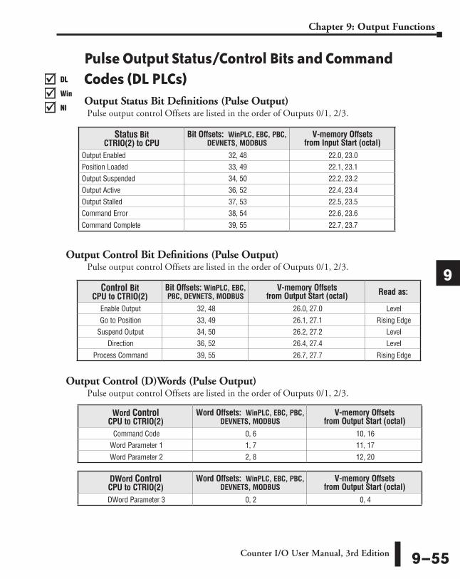
Pulse Output Status/Control Bits and Command Codes (DL PLCs)Output Status Bit Definitions (Pulse Output)Pulse output control Offsets are listed in the order of Outputs 0/1, 2/3.
Output Control Bit Definitions (Pulse Output)Pulse output control Offsets are listed in the order of Outputs 0/1, 2/3.
Output Control (D)Words (Pulse Output)Pulse output control Offsets are listed in the order of Outputs 0/1, 2/3.
Word Control CPU to CTRIO(2)
Word Offsets: WinPLC, EBC, PBC, DEVNETS, MODBUS
V-memory Offsets from Output Start (octal)
Command Code 0, 6 10, 16Word Parameter 1 1, 7 11, 17
Word Parameter 2 2, 8 12, 20
DWord Control CPU to CTRIO(2)
Word Offsets: WinPLC, EBC, PBC, DEVNETS, MODBUS
V-memory Offsets from Output Start (octal)
DWord Parameter 3 0, 2 0, 4
Control Bit CPU to CTRIO(2)
Bit Offsets: WinPLC, EBC, PBC, DEVNETS, MODBUS
V-memory Offsets from Output Start (octal) Read as:
Enable Output 32, 48 26.0, 27.0 LevelGo to Position 33, 49 26.1, 27.1 Rising Edge
Suspend Output 34, 50 26.2, 27.2 Level Direction 36, 52 26.4, 27.4 Level
Process Command 39, 55 26.7, 27.7 Rising Edge
Status Bit CTRIO(2) to CPU
Bit Offsets: WinPLC, EBC, PBC, DEVNETS, MODBUS
V-memory Offsets from Input Start (octal)
Output Enabled 32, 48 22.0, 23.0Position Loaded 33, 49 22.1, 23.1Output Suspended 34, 50 22.2, 23.2Output Active 36, 52 22.4, 23.4Output Stalled 37, 53 22.5, 23.5Command Error 38, 54 22.6, 23.6
Command Complete 39, 55 22.7, 23.7
DL
Win
NI
���
DL
Win
NI
���
DL
Win
NI
���
DL
Win
NI
���
Counter I/O User Manual, 3rd Edition 9–55
Chapter 9: Output Functions
1
2
3
4
5
6
7
8
9
10
11
12
13
14
A
B
C
D
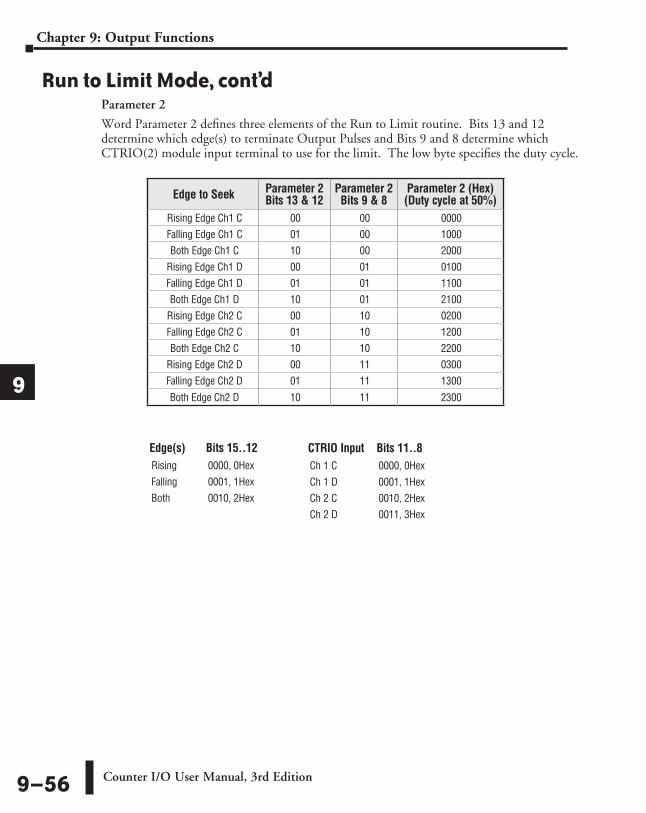
Edge(s) Bits 15..12Rising 0000, 0HexFalling 0001, 1HexBoth 0010, 2Hex
CTRIO Input Bits 11..8Ch 1 C 0000, 0HexCh 1 D 0001, 1HexCh 2 C 0010, 2HexCh 2 D 0011, 3Hex
Run to Limit Mode, cont’dParameter 2
Word Parameter 2 defines three elements of the Run to Limit routine. Bits 13 and 12 determine which edge(s) to terminate Output Pulses and Bits 9 and 8 determine which CTRIO(2) module input terminal to use for the limit. The low byte specifies the duty cycle.
Edge to Seek Parameter 2 Bits 13 & 12
Parameter 2 Bits 9 & 8
Parameter 2 (Hex) (Duty cycle at 50%)
Rising Edge Ch1 C 00 00 0000Falling Edge Ch1 C 01 00 1000Both Edge Ch1 C 10 00 2000
Rising Edge Ch1 D 00 01 0100Falling Edge Ch1 D 01 01 1100Both Edge Ch1 D 10 01 2100
Rising Edge Ch2 C 00 10 0200Falling Edge Ch2 C 01 10 1200Both Edge Ch2 C 10 10 2200
Rising Edge Ch2 D 00 11 0300Falling Edge Ch2 D 01 11 1300
Both Edge Ch2 D 10 11 2300
Counter I/O User Manual, 3rd Edition9–56
Chapter 9: Output Functions
1
2
3
4
5
6
7
8
9
10
11
12
13
14
A
B
C
D
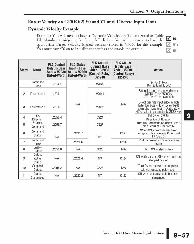
Run at Velocity on CTRIO(2) Y0 and Y1 until Discrete Input Limit
Dynamic Velocity Example
Steps NamePLC Control
Outputs Base Addr = V2030 (Bit-of-Word)
PLC Status Inputs Base
Addr = V2000 (Bit-of-Word)
PLC Control Outputs Base Addr = V2030
(Control Relay) D2-240
PLC Status Inputs Base
Addr = V2000 (Control Relay)
D2-240
Action
1 Command Code V2040
N/A
V2040
N/A
Set to 21 Hex (Run to Limit Mode)
2 Parameter 1 V2041 V2041Set initial run frequency, decimal
CTRIO: 20Hz-25000Hz CTRIO2: 20Hz - 64000Hz
3 Parameter 2 V2042 V2042Select discrete input edge in high byte, low byte = duty cycle (1-99) Example: rising input 1D at Duty =
45%, set this parameter to 212D Hex
4 Set Direction V2056.4 C224 Set ON or OFF for
Direction of Rotation
5 Process Command V2056.7 C227 Turn ON Command Complete status
bit is returned (see step 6)
6 Command Status N/A
V2022.7N/A
C127When ON, command has been
accepted, clear Process Command bit (step 5)
7 Command Error V2022.6 C126 ON if Command or Parameters are
invalid
8 Enable Output V2056.0 N/A C220 N/A Turn ON to start pulses
9Output Active Status
N/A V2022.4 N/A C124 ON while pulsing, OFF when limit has stopped pulsing
10 Suspend Output V2056.2 N/A C222 N/A Turn ON to “pause” output pulses
without resetting pulse count
11 Output Suspended N/A V2022.2 N/A C122 ON when out pulse train has been
suspended
DL
Win
NI
���
DL
Win
NI
���
DL
Win
NI
���
DL
Win
NI
���
Example: You will need to have a Dynamic Velocity profile configured as Table File Number 1 using the Configure I/O dialog. You will also need to have the appropriate Target Velocity (signed decimal) stored in V3000 for this example. You must turn C0 on to initialize the settings and enable the output.
Counter I/O User Manual, 3rd Edition 9–57
Chapter 9: Output Functions
1
2
3
4
5
6
7
8
9
10
11
12
13
14
A
B
C
D
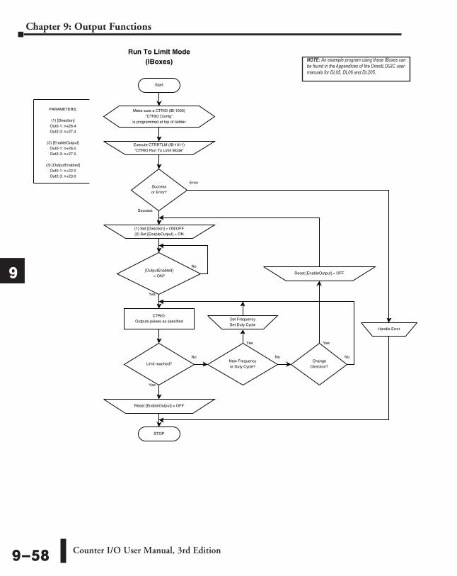
Start
Run To Limit Mode(IBoxes)
Error
Success
PARAMETERS:
(1) [Direction]Out0-1: n+26.4Out2-3: n+27.4
(2) [EnableOutput]Out0-1: n+26.0Out2-3: n+27.0
(3) [OutputEnabled]Out0-1: n+22.0Out2-3: n+23.0
CTRIO:Outputs pulses as specified
Execute CTRRTLM (IB-1011)"CTRIO Run To Limit Mode"
Successor Error?
STOP
Handle Error
[OutputEnabled]= ON?
No
Yes
Limit reached?Change
Direction?
Reset [EnableOutput] = OFF
(1) Set [Direction] = ON/OFF(2) Set [EnableOutput] = ON
Reset [EnableOutput] = OFF
New Frequencyor Duty Cycle?
Set FrequencySet Duty Cycle
No No No
Yes
Yes Yes
Make sure a CTRIO (IB-1000)"CTRIO Config"
is programmed at top of ladder
NOTE: An example program using these IBoxes can be found in the Appendices of the DirectLOGIC user manuals for DL05, DL06 and DL205.
Counter I/O User Manual, 3rd Edition9–58
Chapter 9: Output Functions
1
2
3
4
5
6
7
8
9
10
11
12
13
14
A
B
C
D
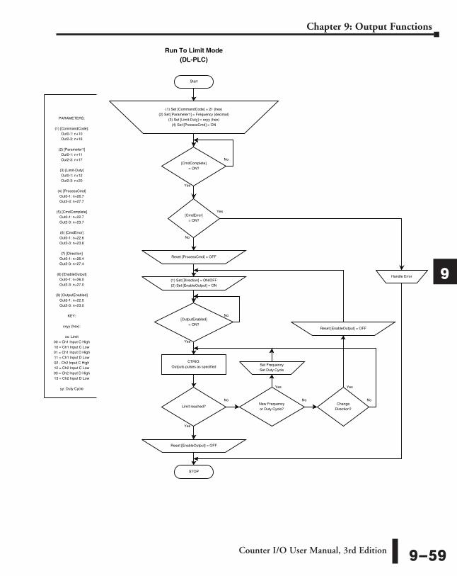
Start
Run To Limit Mode(DL-PLC)
Yes
No
[CmdComplete]= ON?
Yes
No
PARAMETERS:
(1) [CommandCode]:Out0-1: n+10Out2-3: n+16
(2) [Parameter1]Out0-1: n+11Out2-3: n+17
(3) [Limit-Duty]Out0-1: n+12Out2-3: n+20
(4) [ProcessCmd]Out0-1: n+26.7Out2-3: n+27.7
(5) [CmdComplete]Out0-1: n+22.7Out2-3: n+23.7
(6) [CmdError]Out0-1: n+22.6Out2-3: n+23.6
(7) [Direction]Out0-1: n+26.4Out2-3: n+27.4
(8) [EnableOutput]Out0-1: n+26.0Out2-3: n+27.0
(9) [OutputEnabled]Out0-1: n+22.0Out2-3: n+23.0
KEY:
xxyy (hex):
xx: Limit00 = Ch1 Input C High10 = Ch1 Input C Low01 = Ch1 Input D High11 = Ch1 Input D Low02 - Ch2 Input C High12 = Ch2 Input C Low03 = Ch2 Input D High13 = Ch2 Input D Low
yy: Duty Cycle
CTRIO:Outputs pulses as specified
(1) Set [CommandCode] = 21 (hex)(2) Set [Parameter1] = Frequency (decimal)
(3) Set [Limit-Duty] = xxyy (hex)(4) Set [ProcessCmd] = ON
[CmdError]= ON?
Reset [ProcessCmd] = OFF
STOP
Handle Error
[OutputEnabled]= ON?
No
Yes
Limit reached?Change
Direction?
Reset [EnableOutput] = OFF
(1) Set [Direction] = ON/OFF(2) Set [EnableOutput] = ON
Reset [EnableOutput] = OFF
New Frequencyor Duty Cycle?
Set FrequencySet Duty Cycle
No No No
Yes
Yes Yes
Counter I/O User Manual, 3rd Edition 9–59
Chapter 9: Output Functions
1
2
3
4
5
6
7
8
9
10
11
12
13
14
A
B
C
D
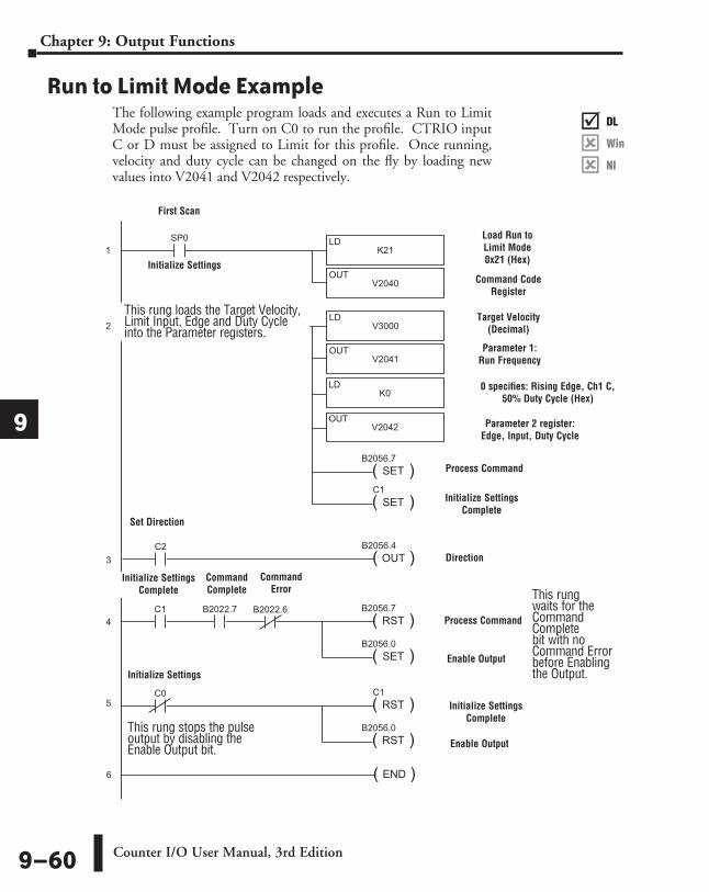
Run to Limit Mode ExampleThe following example program loads and executes a Run to Limit Mode pulse profile. Turn on C0 to run the profile. CTRIO input C or D must be assigned to Limit for this profile. Once running, velocity and duty cycle can be changed on the fly by loading new values into V2041 and V2042 respectively.
SP0
K21LD
V2040OUT
1
( )SET
C1
C0
V3000LD
V2041OUT
2
( )SET
B2056.7
C1 B2022.7 B2022.6
( )RST
B2056.7
( )SET
B2056.0
C0
( )RST
C1
( )RST
B2056.0
( )END6
DirectSOFT 32
3
4
K0LD
V2042OUT
C2
( )OUT
B2056.4
5
First Scan
Load Run to Limit Mode 0x21 (Hex)
Command Code Register
Target Velocity (Decimal)
Parameter 1: Run Frequency
0 specifies: Rising Edge, Ch1 C, 50% Duty Cycle (Hex)
Parameter 2 register: Edge, Input, Duty Cycle
Direction
Initialize Settings Complete
Process Command
Process Command
Enable Output
Initialize Settings Complete
Enable Output
Initialize Settings
Initialize Settings
This rung waits for the Command Complete bit with no Command Error before Enabling the Output.
This rung loads the Target Velocity, Limit Input, Edge and Duty Cycle into the Parameter registers.
Initialize Settings Complete
Command Complete
Command Error
Set Direction
This rung stops the pulse output by disabling the Enable Output bit.
DL
Win
NI
���
DL
Win
NI
���
DL
Win
NI
���
DL
Win
NI
���
Counter I/O User Manual, 3rd Edition9–60
Chapter 9: Output Functions
1
2
3
4
5
6
7
8
9
10
11
12
13
14
A
B
C
D
DL
Win
NI
���
DL
Win
NI
���
DL
Win
NI
���
DL
Win
NI
���
Run to Position Mode Run to Position is used to make a simple move to a new position. If using a CTRIO2 module, consider using Dynamic Positioning Plus instead. Dynamic Positioning Plus is almost always the better choice.
Run to Position Mode is not defined or created using the Pulse Profiles Table dialog in CTRIO Workbench. However, an output must be configured for Pulse (Step/Direction) or Pulse (CW/CCW) using the Configure IO dialog. Also, an input must be configured as a counter. The profile parameters are specified in CPU/controller memory registers. There are no acceleration ramps with Run to Limit Mode. The output will step directly to the specified frequency and duty cycle. Use caution when choosing the frequency to avoid stalling a stepper.
The user specifies the target frequency, pulse train duty cycle, input function to compare, direction and target position. The current position is obtained from the specified Input Function (i.e. Quadrature counter). When the current position satisfies the comparison specified, the pulse output is disabled. The comparison of the current and target positions can be based on greater than or equal to or less than operators.
NOTE: Run to Position Mode controls the pulse outputs directly from the CPU/controller program. No CTRIO Workbench Pulse Profile is required for this mode.
The Run to Position Mode command (Command = 0022Hex/BCD) allows generating output pulses at a steady frequency until some value has been reached on a counter input. Select the direction using the direction bit. Set Word Parameter 1 to the desired Frequency. Set Word Parameter 2 Low Byte to the Duty Cycle and the High Byte to the Compare Functions as defined below. Leaving the Duty Cycle set to 0 achieves the default (50%), otherwise it can be set in 1% increments by writing this value from 1 to 99 Hex/BCD.Word Parameter 3 specifies the value that Input Function will compare against.
Counter I/O User Manual, 3rd Edition 9–61
Chapter 9: Output Functions
1
2
3
4
5
6
7
8
9
10
11
12
13
14
A
B
C
D
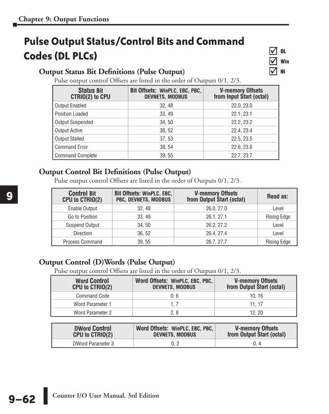
Pulse Output Status/Control Bits and Command Codes (DL PLCs)
Output Status Bit Definitions (Pulse Output)Pulse output control Offsets are listed in the order of Outputs 0/1, 2/3.
Output Control Bit Definitions (Pulse Output)Pulse output control Offsets are listed in the order of Outputs 0/1, 2/3.
Output Control (D)Words (Pulse Output)Pulse output control Offsets are listed in the order of Outputs 0/1, 2/3.
Word Control CPU to CTRIO(2)
Word Offsets: WinPLC, EBC, PBC, DEVNETS, MODBUS
V-memory Offsets from Output Start (octal)
Command Code 0, 6 10, 16Word Parameter 1 1, 7 11, 17
Word Parameter 2 2, 8 12, 20
DWord Control CPU to CTRIO(2)
Word Offsets: WinPLC, EBC, PBC, DEVNETS, MODBUS
V-memory Offsets from Output Start (octal)
DWord Parameter 3 0, 2 0, 4
Control Bit CPU to CTRIO(2)
Bit Offsets: WinPLC, EBC, PBC, DEVNETS, MODBUS
V-memory Offsets from Output Start (octal) Read as:
Enable Output 32, 48 26.0, 27.0 LevelGo to Position 33, 49 26.1, 27.1 Rising Edge
Suspend Output 34, 50 26.2, 27.2 Level Direction 36, 52 26.4, 27.4 Level
Process Command 39, 55 26.7, 27.7 Rising Edge
Status Bit CTRIO(2) to CPU
Bit Offsets: WinPLC, EBC, PBC, DEVNETS, MODBUS
V-memory Offsets from Input Start (octal)
Output Enabled 32, 48 22.0, 23.0Position Loaded 33, 49 22.1, 23.1Output Suspended 34, 50 22.2, 23.2Output Active 36, 52 22.4, 23.4Output Stalled 37, 53 22.5, 23.5Command Error 38, 54 22.6, 23.6
Command Complete 39, 55 22.7, 23.7
DL
Win
NI
���
DL
Win
NI
���
DL
Win
NI
���
DL
Win
NI
���
Counter I/O User Manual, 3rd Edition9–62
Chapter 9: Output Functions
1
2
3
4
5
6
7
8
9
10
11
12
13
14
A
B
C
D
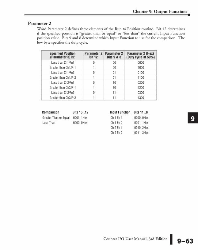
Parameter 2Word Parameter 2 defines three elements of the Run to Position routine. Bit 12 determines if the specified position is “greater than or equal” or “less than” the current Input Function position value. Bits 9 and 8 determine which Input Function to use for the comparison. The low byte specifies the duty cycle.
Specified Position (Parameter 3) is:
Parameter 2 Bit 12
Parameter 2 Bits 9 & 8
Parameter 2 (Hex) (Duty cycle at 50%)
Less than Ch1/Fn1 0 00 0000Greater than Ch1/Fn1 1 00 1000
Less than Ch1/Fn2 0 01 0100Greater than Ch1/Fn2 1 01 1100
Less than Ch2/Fn1 0 10 0200Greater than Ch2/Fn1 1 10 1200
Less than Ch2/Fn2 0 11 0300
Greater than Ch2/Fn2 1 11 1300
Comparison Bits 15..12Greater Than or Equal 0001, 1HexLess Than 0000, 0Hex
Input Function Bits 11..8Ch 1 Fn 1 0000, 0HexCh 1 Fn 2 0001, 1HexCh 2 Fn 1 0010, 2HexCh 2 Fn 2 0011, 3Hex
Counter I/O User Manual, 3rd Edition 9–63
Chapter 9: Output Functions
1
2
3
4
5
6
7
8
9
10
11
12
13
14
A
B
C
D
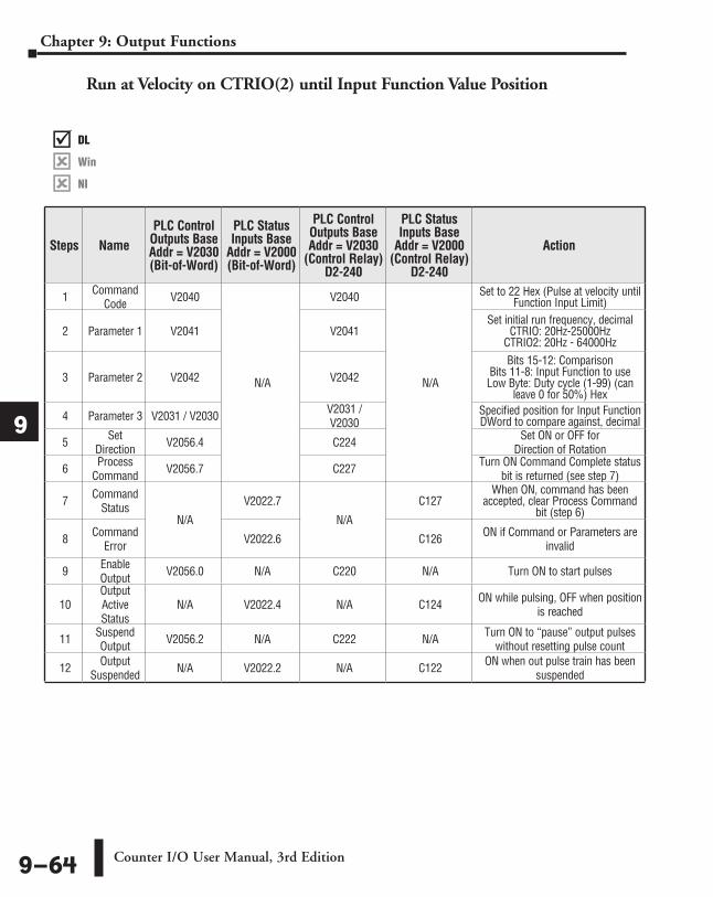
Run at Velocity on CTRIO(2) until Input Function Value Position
Steps NamePLC Control
Outputs Base Addr = V2030 (Bit-of-Word)
PLC Status Inputs Base
Addr = V2000 (Bit-of-Word)
PLC Control Outputs Base Addr = V2030
(Control Relay) D2-240
PLC Status Inputs Base
Addr = V2000 (Control Relay)
D2-240
Action
1 Command Code V2040
N/A
V2040
N/A
Set to 22 Hex (Pulse at velocity until Function Input Limit)
2 Parameter 1 V2041 V2041Set initial run frequency, decimal
CTRIO: 20Hz-25000Hz CTRIO2: 20Hz - 64000Hz
3 Parameter 2 V2042 V2042Bits 15-12: Comparison
Bits 11-8: Input Function to use Low Byte: Duty cycle (1-99) (can
leave 0 for 50%) Hex
4 Parameter 3 V2031 / V2030 V2031 / V2030
Specified position for Input Function DWord to compare against, decimal
5 Set Direction V2056.4 C224 Set ON or OFF for
Direction of Rotation
6 Process Command V2056.7 C227 Turn ON Command Complete status
bit is returned (see step 7)
7 Command Status
N/A
V2022.7
N/A
C127When ON, command has been
accepted, clear Process Command bit (step 6)
8 Command Error V2022.6 C126 ON if Command or Parameters are
invalid
9 Enable Output V2056.0 N/A C220 N/A Turn ON to start pulses
10Output Active Status
N/A V2022.4 N/A C124 ON while pulsing, OFF when position is reached
11 Suspend Output V2056.2 N/A C222 N/A Turn ON to “pause” output pulses
without resetting pulse count
12 Output Suspended N/A V2022.2 N/A C122 ON when out pulse train has been
suspended
DL
Win
NI
���
DL
Win
NI
���
DL
Win
NI
���
DL
Win
NI
���
Counter I/O User Manual, 3rd Edition9–64
Chapter 9: Output Functions
1
2
3
4
5
6
7
8
9
10
11
12
13
14
A
B
C
D

Start
Run To Position Mode(IBoxes)
Error
Success
PARAMETERS:
(1) [Direction]Out0-1: n+26.4Out2-3: n+27.4
(2) [EnableOutput]Out0-1: n+26.0Out2-3: n+27.0
(3) [OutputEnabled]Out0-1: n+22.0Out2-3: n+23.0
CTRIO:Outputs pulses as specified
Execute CTRRTPM (IB-1012)"CTRIO Run To Position Mode"
Successor Error?
STOP
Handle Error
[OutputEnabled]= ON?
No
Yes
Positionreached?
ChangeDirection?
Reset [EnableOutput] = OFF
(1) Set [Direction] = ON/OFF(2) Set [EnableOutput] = ON
Reset [EnableOutput] = OFF
New Frequencyor Duty Cycle?
Set FrequencySet Duty Cycle
No No No
Yes
Yes Yes
Make sure a CTRIO (IB-1000)"CTRIO Config"
is programmed at top of ladder
NOTE: An example program using these IBoxes can be found in the Appendices of the DirectLOGIC user manuals for DL05, DL06 and DL205.
Counter I/O User Manual, 3rd Edition 9–65
Chapter 9: Output Functions
1
2
3
4
5
6
7
8
9
10
11
12
13
14
A
B
C
D
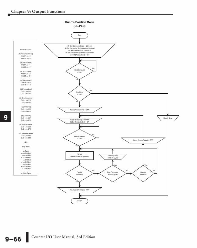
Start
Run To Position Mode(DL-PLC)
Yes
No
[CmdComplete]= ON?
Yes
No
PARAMETERS:
(1) [CommandCode]:Out0-1: n+10Out2-3: n+16
(2) [Parameter1]Out0-1: n+11Out2-3: n+17
(3) [Funct-Duty]Out0-1: n+12Out2-3: n+20
(4) [Parameter3]Out0-1: n+0-1Out2-3: n+4-5
(5) [ProcessCmd]Out0-1: n+26.7Out2-3: n+27.7
(6) [CmdComplete]Out0-1: n+22.7Out2-3: n+23.7
(7) [CmdError]Out0-1: n+22.6Out2-3: n+23.6
(8) [Direction]Out0-1: n+26.4Out2-3: n+27.4
(9) [EnableOutput]Out0-1: n+26.0Out2-3: n+27.0
(10) [OutputEnabled]Out0-1: n+22.0Out2-3: n+23.0
KEY:
xxyy (hex):
xx: Funct00 = <Ch1/Fn110 = >Ch1/Fn101 = <Ch1/Fn211 = >Ch1/Fn202 = <Ch2/Fn112 = >Ch2/Fn103 = <Ch2/Fn213 = >Ch2/Fn2
yy: Duty Cycle
CTRIO:Outputs pulses as specified
(1) Set [CommandCode] = 22 (hex)(2) Set [Parameter1] = Frequency (decimal)
(3) Set [Funct-Duty] = xxyy (hex)(4) Set [Parameter3] = Position (decimal)
(5) Set [ProcessCmd] = ON
[CmdError]= ON?
Reset [ProcessCmd] = OFF
STOP
Handle Error
[OutputEnabled]= ON?
No
Yes
Positionreached?
ChangeDirection?
Reset [EnableOutput] = OFF
(1) Set [Direction] = ON/OFF(2) Set [EnableOutput] = ON
Reset [EnableOutput] = OFF
New Frequencyor Duty Cycle?
Set FrequencySet Duty Cycle
No No No
Yes
Yes Yes
Counter I/O User Manual, 3rd Edition9–66
Chapter 9: Output Functions
1
2
3
4
5
6
7
8
9
10
11
12
13
14
A
B
C
D
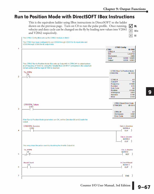
Run to Position Mode with DirectSOFT IBox InstructionsThis is the equivalent ladder using IBox instructions in DirectSOFT to the ladder shown on the previous page. Turn on C0 to run the pulse profile. Once running, velocity and duty cycle can be changed on the fly by loading new values into V2041 and V2042 respectively.
DL
Win
NI
���
DL
Win
NI
���
DL
Win
NI
���
DL
Win
NI
���
Counter I/O User Manual, 3rd Edition 9–67
Chapter 9: Output Functions
1
2
3
4
5
6
7
8
9
10
11
12
13
14
A
B
C
D
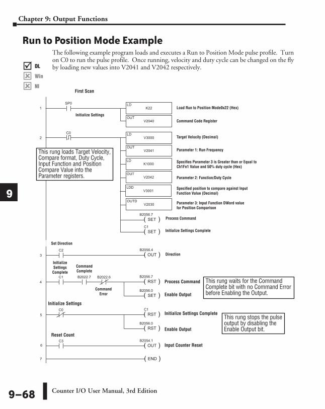
Run to Position Mode ExampleThe following example program loads and executes a Run to Position Mode pulse profile. Turn on C0 to run the pulse profile. Once running, velocity and duty cycle can be changed on the fly by loading new values into V2041 and V2042 respectively.
SP0
K22LD
V2040OUT
1
( )SET
C1
C0
V3000LD
V2041OUT
2
( )SET
B2056.7
C1 B2022.7 B2022.6
( )RST
B2056.7
( )SET
B2056.0
C0
( )RST
C1
( )RST
B2056.0
( )END7
DirectSOFT 32
3
4
K1000LD
V2042OUT
V3001LDD
V2030OUTD
C2
( )OUT
B2056.4
5
C3
( )OUT
B2054.1
6
Load Run to Position Mode0x22 (Hex)
Command Code Register
Target Velocity (Decimal)
Parameter 1: Run Frequency
Direction
Process Command
Initialize Settings Complete
Process Command
Enable Output
Initialize Settings Complete
Enable Output
Parameter 2: Function/Duty Cycle
Specifies Parameter 3 is Greater than or Equal to Ch1Fn1 Value and 50% duty cycle (Hex)
Parameter 3: Input Function DWord value for Position Comparison
Specified position to compare against Input Function Value (Decimal)
Initialize Settings
CompleteCommand Complete
Command Error
This rung waits for the Command Complete bit with no Command Error before Enabling the Output.
Initialize Settings
Initialize Settings
First Scan
This rung loads Target Velocity, Compare format, Duty Cycle, Input Function and Position Compare Value into the Parameter registers.
Set Direction
Input Counter Reset
Reset Count
This rung stops the pulse output by disabling the Enable Output bit.
DL
Win
NI
���
DL
Win
NI
���
DL
Win
NI
���
DL
Win
NI
���
Counter I/O User Manual, 3rd Edition9–68
Chapter 9: Output Functions
1
2
3
4
5
6
7
8
9
10
11
12
13
14
A
B
C
D
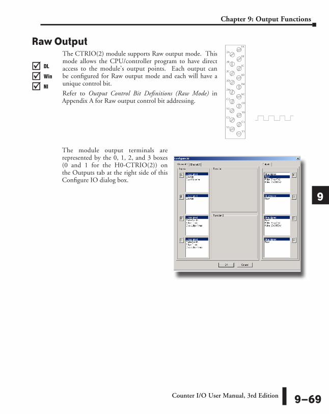
Raw OutputThe CTRIO(2) module supports Raw output mode. This mode allows the CPU/controller program to have direct access to the module’s output points. Each output can be configured for Raw output mode and each will have a unique control bit.
Refer to Output Control Bit Definitions (Raw Mode) in Appendix A for Raw output control bit addressing.
The module output terminals are represented by the 0, 1, 2, and 3 boxes (0 and 1 for the H0-CTRIO(2)) on the Outputs tab at the right side of this Configure IO dialog box.
A
1
1D
1M
NC
C
Y
C1
Y1
1A
1B
C
0
0
2A
2B
2C
2D
2C
2Y
3C
3Y
M2
DL
Win
NI
���
DL
Win
NI
���
DL
Win
NI
���
DL
Win
NI
���
Counter I/O User Manual, 3rd Edition 9–69
Chapter 9: Output Functions
1
2
3
4
5
6
7
8
9
10
11
12
13
14
A
B
C
D
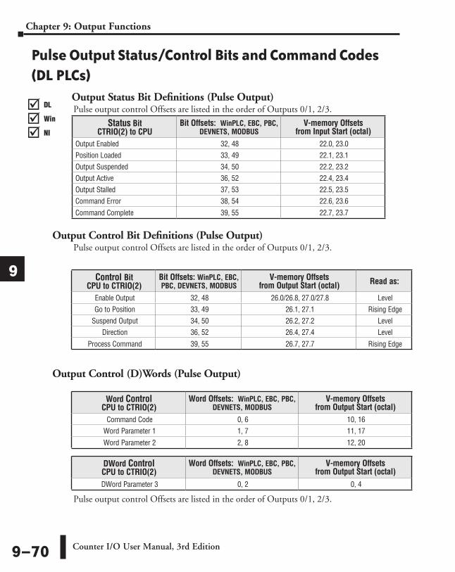
Pulse Output Status/Control Bits and Command Codes (DL PLCs)
Output Status Bit Definitions (Pulse Output)Pulse output control Offsets are listed in the order of Outputs 0/1, 2/3.
Output Control Bit Definitions (Pulse Output)Pulse output control Offsets are listed in the order of Outputs 0/1, 2/3.
Output Control (D)Words (Pulse Output)
Pulse output control Offsets are listed in the order of Outputs 0/1, 2/3.
Word Control CPU to CTRIO(2)
Word Offsets: WinPLC, EBC, PBC, DEVNETS, MODBUS
V-memory Offsets from Output Start (octal)
Command Code 0, 6 10, 16Word Parameter 1 1, 7 11, 17
Word Parameter 2 2, 8 12, 20
DWord Control CPU to CTRIO(2)
Word Offsets: WinPLC, EBC, PBC, DEVNETS, MODBUS
V-memory Offsets from Output Start (octal)
DWord Parameter 3 0, 2 0, 4
Control Bit CPU to CTRIO(2)
Bit Offsets: WinPLC, EBC, PBC, DEVNETS, MODBUS
V-memory Offsets from Output Start (octal) Read as:
Enable Output 32, 48 26.0/26.8, 27.0/27.8 LevelGo to Position 33, 49 26.1, 27.1 Rising Edge
Suspend Output 34, 50 26.2, 27.2 Level Direction 36, 52 26.4, 27.4 Level
Process Command 39, 55 26.7, 27.7 Rising Edge
Status Bit CTRIO(2) to CPU
Bit Offsets: WinPLC, EBC, PBC, DEVNETS, MODBUS
V-memory Offsets from Input Start (octal)
Output Enabled 32, 48 22.0, 23.0Position Loaded 33, 49 22.1, 23.1Output Suspended 34, 50 22.2, 23.2Output Active 36, 52 22.4, 23.4Output Stalled 37, 53 22.5, 23.5Command Error 38, 54 22.6, 23.6
Command Complete 39, 55 22.7, 23.7
DL
Win
NI
���
DL
Win
NI
���
DL
Win
NI
���
DL
Win
NI
���
Counter I/O User Manual, 3rd Edition9–70
Chapter 9: Output Functions
1
2
3
4
5
6
7
8
9
10
11
12
13
14
A
B
C
D

Start
Raw Output(IBoxes)
PARAMETERS:
(1) [EnableOutput]Out0: n+26.0Out1: n+26.8Out2: n+27.0Out3: n+27.8
(2) [RawOutput]Output 0Output 1Output 2Output 3
(3) [OutputEnabled]Out0: n+22.0Out1: n+22.8Out2: n+23.0Out3: n+23.8
*(4) [SysOutStat]Out0: n+25.8Out1: n+25.10Out2: n+25.12Out3: n+25.14
*Optional wayof monitoring
output
CTRIO:Turns ON [RawOutput]
Set [EnableOutput] = ON
[OutputEnabled]= ON?
No
Yes
STOP
[SysOutStat]= ON?
No
Yes
NOTE: An example program using these IBoxes can be found in the Appendices of the DirectLOGIC user manuals for DL05, DL06 and DL205.
Counter I/O User Manual, 3rd Edition 9–71
Chapter 9: Output Functions
1
2
3
4
5
6
7
8
9
10
11
12
13
14
A
B
C
D
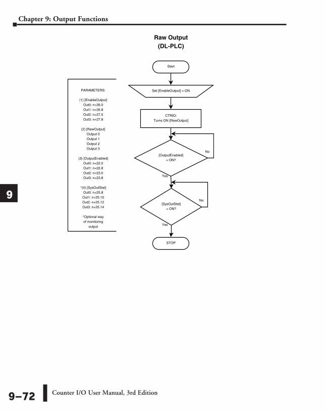
Start
Raw Output(DL-PLC)
PARAMETERS:
(1) [EnableOutput]Out0: n+26.0Out1: n+26.8Out2: n+27.0Out3: n+27.8
(2) [RawOutput]Output 0Output 1Output 2Output 3
(3) [OutputEnabled]Out0: n+22.0Out1: n+22.8Out2: n+23.0Out3: n+23.8
*(4) [SysOutStat]Out0: n+25.8Out1: n+25.10Out2: n+25.12Out3: n+25.14
*Optional wayof monitoring
output
CTRIO:Turns ON [RawOutput]
Set [EnableOutput] = ON
[OutputEnabled]= ON?
No
Yes
STOP
[SysOutStat]= ON?
No
Yes
Counter I/O User Manual, 3rd Edition9–72
Chapter 9: Output Functions
1
2
3
4
5
6
7
8
9
10
11
12
13
14
A
B
C
D