Embed Size (px)
Citation preview


CHAPTER 9 “MEMBERS DESIGN”
2
CONTENTS
I. DETAILED DESCRIPTION OF THE NEW INTERFACE 4
1. Members Design 4
1.1. Scenarios 4
1.2. Steel 13
CHAPTER 9 “MEMBERS DESIGN”
3
I. THE NEW UPGRADED INTERFACE of SCADA Pro

CHAPTER 9 “MEMBERS DESIGN”
4
I. DETAILED DESCRIPTION OF THE NEW INTERFACE In the new upgraded SCADA Pro all program commands are grouped in 11 Units.
1. Members Design
The 9th Unit entitled "Members Design" contains the following 8 groups of commands:
1. Scenarios 2. Beams 3. Capacity Design 4. Columns 5. Footings 6. Slabs - Mesh 7. Steel 8. Timber 9. Masonry Design – 2D Diagrams
Since model analysis has been completed, the design checks of the structural elements are
applied according to the design code provisions, defined in the tab “Member Design”. The reinforcement of the structural elements is calculated according to the design checks.
1.1. Scenarios
The “Scenarios” command group contains the commands for the creation of a new scenario as well as the editing of the parameters of the design checks and reinforcement in every type of structural elements.
New: This command is used to create a new scenario. Type a name, select the corresponding
design regulation and then press the button .
The selection of the design code corresponds to the design checks of the structural elements and the calculation of the steel reinforcement. For the SBC 304, you must create the SBC304 scenario for the design and the checks of the concrete structures.

CHAPTER 9 “MEMBERS DESIGN”
5
To modify an existing scenario press the button “Update” . In the field “Design Delete” activate the corresponding checkbox and then press “Apply”, to delete the results of the previous design checks. Repeat using other combinations or parameters or scenarios, etc.
List: The drop-down list includes all created scenarios. When you select a scenario, it becomes active. This means that the scenario will be used for the design checks.
Parameters: This command is used for the definition of all design check parameters:
Regardless of the material, the calculation of combinations is a prerequisite for the design. The selection of the existing .cmb combinations file is made:
- from the dropdown list with automatic calculation or
- through the command that opens the folder with the
existing .cmb files. Select the file and press .

CHAPTER 9 “MEMBERS DESIGN”
6
Depending on the case and the fulfilled conditions, you can use either the static or dynamic combination for design. You can also select combinations from different analysis scenarios to check the deviations, on the member’s design, between them. In “Combinations” tab the combinations list is displayed. The first number is the load combination’s serial number. The column “SE/ST” indicates the limit state of the combination and the column “Dir.” indicates the direction of the participation for the specific capacity design combination. By using the following bar, you can modify both the limit state and the direction by pressing the corresponding button.
The label “No” means that the specific combination is excluded from the capacity design. SECTION 2.3 COMBINING FACTORED LOADS USING STRENGTH DESIGN
CHAPTER 9 “MEMBERS DESIGN”
7
SBC 301
SBC 301
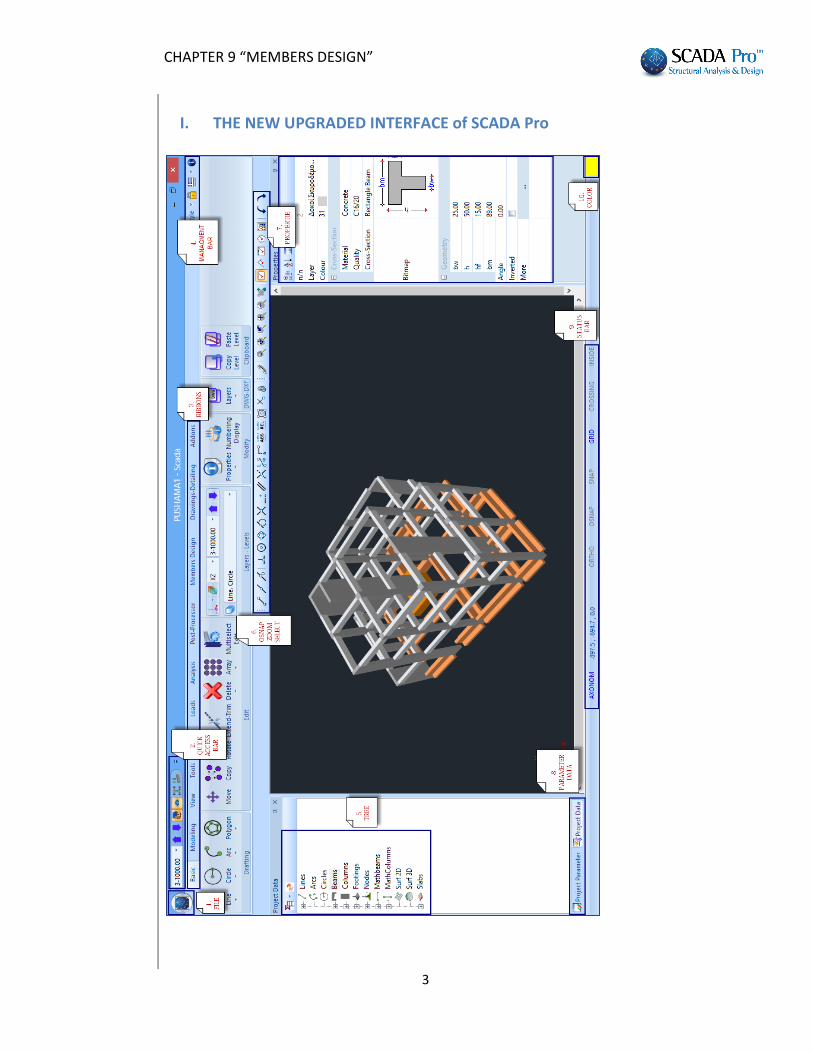
2.3.2. Basic Combinations. Structures, components, and foundations shall be designed so that their design strength equals or exceeds the effects of the factored loads in the following combinations: U = 1.4 (D + F) (9-1) U = 1.4 (D + F + T) + 1.7(L + H) + 0.5 (Lr or R) (9-2) U = 1.2D + 1.6 (Lr or R) + (1.0 L or 0.8 W) (9-3) U = 1.2D + 1.6W + 1.0L + 0.5(Lr or R) (9-4) U = 1.2D + 1.0E + 1.0L (9-5) U = 0.9D + 1.6W + 1.6H (9-6) U = 0.9D + 1.0E + 1.6H (9-7) In the preceding expressions, the following values are used: U = the design or ultimate load the structure needs to be able to resist D = dead load L = live load Lr = roof live load S = snow load R = rain load W = wind load E = seismic or earthquake load effects “Level Multipliers”: In this field, you can increase or decrease the seismic actions in any direction and level, by typing different factors.
Press the button in order to take into account the P-Delta effect during the design check. The stress resultants will be increased automatically at the corresponding levels, where 0.1 < θ <θmax. 10.9.7.2 When the stability coefficient (θ) is greater than 0.10 but less than or equal to θ max the incremental factor related to P-delta effects (ad) shall be determined by rational analysis. To obtain the story drift for including the P-delta effect, the design story drift determined in Section 10.9.7.1 shall be multiplied by 1.0/(1 -θ).
For modification purposes, press the following button .
The next section regards to the “Steel cross sections” check parameters and displays the following dialog box:

CHAPTER 9 “MEMBERS DESIGN”
8
First select a layer. Click one from the list, or more using “ctrl”, or all using “Select All”. (By pressing the button “Deselect All” cancel the previous layers’ selection.) Then activate one or more design checks with a tick on the corresponding checkbox and press the corresponding button to specify the parameters. The parameters defined for one layer can be copied to other layers, using the command "Copy". Select a layer define the parameters press “Copy” select another layer press “Paste”. Suppose you have set all parameters for the layer Steel Columns and you want to pass these parameters to Steel Beams. Activate the check box next to "Default" and automatically all parameters become selected.

CHAPTER 9 “MEMBERS DESIGN”
9
Then press “Copy”, select layer Steel Beams and press “Paste” (now activated).
Now all the parameters defined for Steel Columns are defined also for the layer Steel Beams. An alternative method to set the same parameters to all layer including steel sections, is selecting all layer pressing "Select all" button and set once the parameters for each check category. Note that at least one (or more) layer should be selected in order to set parameters.

CHAPTER 9 “MEMBERS DESIGN”
10
PARAMETERS
The Selection it is not applied in SBC 306 Code.
Press the button “TENSION” to define the parameters that correspond to the the position of the hole check (SECTION 2.2) and the calculation of the net Area An:

CHAPTER 9 “MEMBERS DESIGN”
11
Here the user defines whether to consider the reduction of the tensile strength of the section due to the bolt holes of the connections or not. The data in the fields of the dialog box are derived from the design checks of the connections. For that reason, the verification of the connections must be preceded. Specify the spacing of the centers of two consecutive holes, the diameter of the hole and the number of rows of bolt holes. In case of L section specify the parameters on the bottom of the dialog box in the field “Section L”. The safety factor is not applied to the SBC 306.
Press the button “SHEAR” in order to define if the elements of the selected layer contain stiffeners and what type; web stiffeners or intermediate stiffeners. Also define the spacing between the stiffeners and the type of the connection (rigid or not rigid).

CHAPTER 9 “MEMBERS DESIGN”
12
Click the button “TORSION” to define whether the structural elements of the selected layer are loaded by a distributed or concentrated torsional moment, or not. In the following dialog box you may as well define the support conditions based on the corresponding figures. Select the type of moment and set (i) the relative distances from the start and the end, (ii) the value of the moment and (iii) the length of the element in the corresponding fields. Also, set the support condition by typing in the "Type" field the values 0, 1, 2 or 3.
For all design checks presented in the figure on the left, define the safety factor in the dialog box that appears when you click one of the five buttons. The safety factor is the ratio of the resistance value versus the corresponding design value, which is set 1.0 by default.

CHAPTER 9 “MEMBERS DESIGN”
13
1.2. Steel
“Steel Design” command group contains commands for the cross-sections design, the buckling resistance and the steel connections design.
Always remember to calculate the corresponding load combinations in the parameters dialog box.
Cross Section Design This command is applicable only to EC3 and should be not used with SBC 306.
Buckling Members Input The buckling resistance check is one of the main design checks for steel structural members. Select the command “Buckling Members Input”, to apply on each member of each layer the following resistance checks according to the SBC 306:
ULS (Ultimate limit state) SLS (Serviceability limit state)
Tension Check (Section 4.1) Member Deflection check
Slenderness Check (Section 2.7) Node Displacement check
Design for Flexure - Yielding (Par. 6.1.1)
Design for Shear (Section 6.2)
Flexural Buckling Check (Section 5.2)
Flexural-Torsional Buckling Check (Par. 5.3.1)
Section Lateral - Torsional Buckling (Par. 6.1.2)
Element Lateral - Torsional Buckling (Par. 6.1.2.4)
Torsion (AISC Chapter H3)
Bending and Axial Force Check (Section 8.1)
Torsion and combined Torsion, Flexure, Shear and/or Axial Force Check (Section 8.2)

CHAPTER 9 “MEMBERS DESIGN”
14
Selecting the command opens the following window:
Checking is performed by layer. So first select the layer from the drop down list and the "Member" list loads all members of this layer and its cross sections.
For example, select from the drop-down list the layer “Steel Columns”. In the “Members” list all the structural members that belong in the selected layer are displayed. If you want to define different parameters to some of them, you can create different “Groups” in the same layer.

CHAPTER 9 “MEMBERS DESIGN”
15
Lateral Buckling
The program has two default Groups: "Beams" and "Columns".
If you want to apply the same parameters to all members of the layer, then set the parameters once, keep the default name "Columns" and press the "Apply to all members of the layer". Calculations will consider the same parameters for all members of the layer. Otherwise in order to set different parameters for some of the members of the layer, the procedure that should be followed is explained below. But first let’s see how to set the parameters. Select a “Layer” and click on the “Parameters”, and the following dialog box opens:
In the "Group Name" you see the name of the parameter group. If you want to create your own group, give a new name and press the button "New Group Creation". In the "Safety Factor" you can set the limit for the program for the design checks: the intensive forces to the respective strength of the member. The default value is 1. The "Limit of internal forces" is the limit that the program uses to take into consideration (or to ignore) the intensive sizes. The rest of the form is divided into 4 parts, one for each check:

CHAPTER 9 “MEMBERS DESIGN”
16
Lateral Buckling resistance check: Activate the corresponding checkbox. Set the length of the structural member and the buckling lengths for both Y and Z directions. On the field
“Member’s Length” activate the label “Real” and type the real length in m, or
activate the label “Coefficient” and type a factor (“1” means the real length).
The parameter "Buckling Lengths" depends on the support conditions of the structural member.
Click on the following button to open the following list and select the appropriate conditions so that the program automatically inserts the corresponding factor.
The icons are divided into two groups: The first group includes icons with a specific factor depending on the member support conditions
By choosing you can define the positions of lateral blocks, if there are any in order to calculate the corresponding reduced buckling lengths.
The second group
includes cases of members in multi-storey steel structures and allows setting the concurrent to the node members.
Choosing (the most complex case) the user sets for the vertical member the 6 Members (2 vertical and 4 horizontal) that offers succor to it
(3 on the top and 3 at the end). Selecting the icon displays the following dialog box:

CHAPTER 9 “MEMBERS DESIGN”
17
Flexural Buckling
where for the respective fields indicate graphically the respective members that offer succor to the top and the bottom nodes of the member that specify the buckling length. Every time you click a member, in the corresponding field, the number of the cross-section and the length is automatically filled in. To select the members, follow the indications on the left (Top column, Beam top Left, etc.). Then indicate their orientation and especially for beams the type of support on the other end, and the type of load imposed on them. Pressing "OK", on buckling length the corresponding icon and the factor -1 appears, which generally means that the program based on the data you entered automatically calculates the buckling length for this member.
Finally, by choosing user can type his own buckling length.
set if the frame where member belongs is transposable or irremovable.

CHAPTER 9 “MEMBERS DESIGN”
18
Flexural Buckling resistance check:
Activate the checkbox and press The “End Constraints” window, containing the various types of constraints opens. Press one of the first four buttons in order to automatically calculate the flexural buckling factor:
The last one gives user the opportunity to consider different constrains along the same member.
The next parameter refers to the load type of the member at the local axis y, and z respectively. By selecting the corresponding icon, the following options appear: Where you choose the type of Member Loading.

CHAPTER 9 “MEMBERS DESIGN”
19
Lateral Torsion Buckling
Serviceability
Finally, the last parameter concerns the determination of the Loading level of the member. The following five options are displayed by selecting the icon. Loading levels for each icon: 1st icon: on the upper flange of the element 2nd icon: near and upward from the axis of symmetry
of the element 3rd icon: on the axis of symmetry of the element 4th icon: near and below the axis of symmetry of the element 5th icon: on the lower flange element. For Lateral Torsion Buckling resistance check: activate the corresponding checkbox.
Note: For the lateral buckling and the lateral torsion buckling resistance check, the parameters are the same.
For Serviceability checks: activate the checkbox “Serviceability Check” and the checkboxes
“Member Deflection Limits” and “Node Displacement Limits”. Then type the corresponding values in each direction, X and Z. For example in the figure on the left, the limits are defined as l/200 and l/150, where l is the member’s length.
Finish the parameters’ input and then press the button "OK" to return to the previous dialog box.

CHAPTER 9 “MEMBERS DESIGN”
20
To apply the parameters that you set to all members of a layer, select the command "Apply to all members of the Layer". Finally click the button "Check in Layer" to check every member of the current layer, for every load combination. The results of the design checks are displayed in the black window that becomes green if it the checks are satisfied of all members of the active layer and red, if not.
To define another set of parameters for some of the members of the layer follow these steps:
1st step: Press the button "Parameters" and open again the parameters dialog box. Type the "Group Name" for the new set of parameters that will be created and press the button "New Group Creation". Then set the parameters and press the button "OK".
CHAPTER 9 “MEMBERS DESIGN”
21
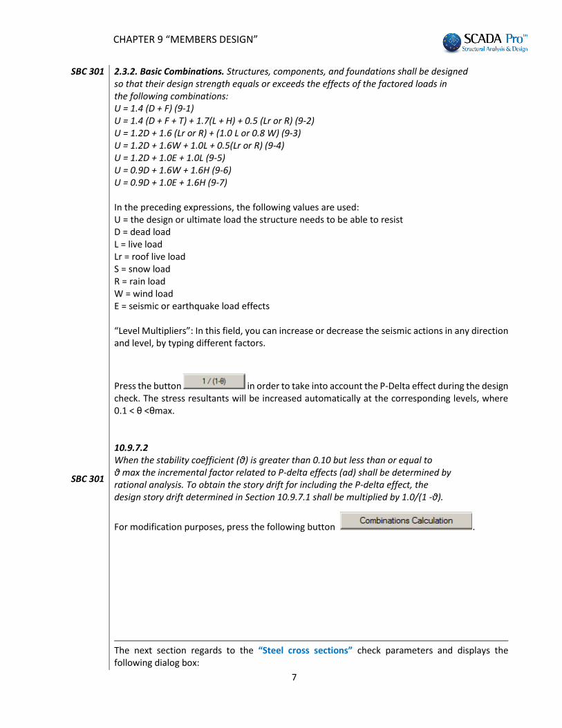
2nd step: define the members of the layer that will belong in “Columns_1” group. Returning to the original dialog, the only member that gets the parameters automatically, is the current member in the list of members. All other members have the parameters of the group “Columns” To move the members from a group to another, select each one from the Members list and change the Group.
As soon as the layer check is completed, the color of the window on the right gives the information:
Red: if there is a failure Green: if there is no failure. Double click ok the colored window, opens the dialog box containing members check summary results:

CHAPTER 9 “MEMBERS DESIGN”
22
The first column indicates the number of the member, the second column indicates the cross section and in the next five columns the least favorable ratio of strength and the combination number from which this ratio was resulted is displayed. Greens are the ratios below unity and red the ratios above it. "Not Required" means that there is no corresponding size or that the intensive axial force is tensile and not compressive.
Selecting the button the program displays the results report. All the results are for each layer and for each member that belongs to this layer.
The first part contains all the data for the specific cross section.
The next section contains the resistance factors for each internal force, according to SBC 306
The next section contains the results for section classification. The check is performed for Web and Flange separately and for the hole cross section.

CHAPTER 9 “MEMBERS DESIGN”
23
Next, there are three checks for Tension, Flexure and Shear.
Checks for Flexural Buckling and Flexural-Torsional Buckling are following. Please note that the last one has different data according to if the factor λ. Slenderness check is included.
The Lateral – Torsional Buckling check which follows, is performed per section and per element of the section.
The Torsion check is performed according to AISC code

CHAPTER 9 “MEMBERS DESIGN”
24
The Bending and Axial force check follows
Last check is the Torsion and combined Torsion, Flexure, Shear and/or Axial force. This check is performed with the calculation of the normal and Shear Stresses in the cross section.
Connections The last command of the group command “Steel Members Design” is the “Steel Connections”, used for the steel connections’ design. Select the command and choose one of the following steps: Α) Right click on the screen to open the library that contains all the available steel connections and select the appropriate one. Click on the button “Next Connection Group” to see more connections.

CHAPTER 9 “MEMBERS DESIGN”
25
Β) Select with left click the members that you want to connect together. Then right click to open a library that contains only the suitable connections for the selected members.

CHAPTER 9 “MEMBERS DESIGN”
26
EXAMPLE: Left click to select member 30 (column) and member 116 (beam) and right click to open the library with the 4 possible types of connection. Select the last one “Beam to Column (Web) Γ”. Fist, type a name (e.g. dok_styl_asthenis ).
No space between words. Then, select the “Member Group Definition (Node)” command and in the dialog box you can add more groups of members with the same connection features (i.e. column – beam) or type your own values for the stress resultants Ν, Μ, V for the existing groups. To add groups of members, click into the field “Lower Column” and pick the column 19. Then click into the field “Right Beam” and pick the beam 115 (or just enter the numbers in the corresponding fields) and then click the button “Add”.
Use this dialog box for the design of steel connections with the same type and the same cross-sections in total (i.e. column IPE 450 - beam IPE 330).
The program calculates automatically the forces and proceeds with connection’s design, based on the less favorable load combination. So you don’t have to guess the point of your structure, where the less favorable beam - column connection in the minor axis will be developed. Furthermore, if this connection is satisfied, then all the other connections with the same type will be automatically satisfied, too.
At the end, click “Exit” and select the command “Edit Connections (Geometry/Checks)”. In the new dialog box you can define the type and the geometry of the specific connection. Select the type and enter the geometrical parameters of the cross-section. Then select the material and define the bolts’ parameters. In each type of connection, the relative parameter fields are active. Then for the design calculations by using the analysis’ combinations select the command “Calculation (Combinations)”. First the program performs the geometrical checks of the connection (e.g. if the bolts are located too close to the edge of the plate). If there is a problem, the corresponding error message appears in the field on the right. In the specific connection, change the distance e1 from 14 to 15 cm and then click again the button "Calculation (Combinations)".

CHAPTER 9 “MEMBERS DESIGN”
27
Click the button “3D” to see a three-dimensional representation of the connection that is updated as you change the parameters. The buttons “1”, “2”, “3” are used for the display of the two side views (1 & 2) and the plan view (3). The button “Σ/Κ” is used for the display of the three-dimensional representation of the welds and bolts.

CHAPTER 9 “MEMBERS DESIGN”
28
If the geometrical checks are satisfied, the program calculates and displays all Eurocode 3 design checks for the connection. Click “Simplified” to see the results. Green fonts means adequacy and red failure. If all checks are satisfied the program will be able to save the connection and generate the drawings automatically. Otherwise the procedure will stop and you need to change some values of the connection to continue. To read the main results click the button “Results” and for all the results, click the button “Exploration”. The displayed *txt files are those generated by the program for the printout. Click “Save” and then “Exit” to return to the connections’ window. Connections’ drawings are located in the folder of the project “sxedia”: C:\scadapro\ “project name” \scades_Synd\sxedia You can import them using:

CHAPTER 9 “MEMBERS DESIGN”
29
And in the dialog box: in Files of Type select Scada Connection press Find
In the Search File window that opens, select the connection to import the designs, views and section, and the detailed table of the link elements.

CHAPTER 9 “MEMBERS DESIGN”
30