Embed Size (px)
Citation preview

ERG2310A: Principles of Communication Systems (2002-2003) 25Yang Yang, IE, CUHK
Chapter 7: Pulse Modulation
Pulse shaping (continued)
For multichannel TDM case: and
For finite-width sample pulses:
where is the Fourier transform of sample pulse (slides 5-7).Problem (Example 7.3.1): Twenty PAM signals, each band-limited to 3 kHz and sampled at 8 kHz, are time-multiplexed prior to transmission. Choose a raised-cosine filter characteristic that will permit transmission of this multiplexed signal within an absolute maximum bandwidth of 120 kHz.Solution: (1) We know , , .
(2) , .
T xBxT
kHz 3=mf kHz 81 =−T20=n
kHz 1202
1≤
+=
xx T
B α 5.0≤αkHz160
1 n
TTx ==
B
)()()(
ωωω
QXH =)(ωX
)(ωQ

ERG2310A: Principles of Communication Systems (2002-2003) 26Yang Yang, IE, CUHK
Chapter 7: Pulse ModulationDifferent analog pulse modulation methods (slide 2)
PAM: constant-width, uniformly spaced pulses whose amplitude isproportional to the values of at the sampling instants.
PWM: constant-amplitude pulses whose width is proportional tothe values of at the sampling instants.
PPM: constant-width, constant-amplitude pulses whose position isproportional to the values of at the sampling instants.
Remarks(1) PWM is a popular choice where the remote proportional control
of a position or a position rate is desired.(2) Disadvantages of PWM include the necessity for detection of both pulse
edges and a relatively large guard time is needed.(3) Only the trailing edges of the PWM waveforms contain the modulating
information. PPM conveys only the timing marks of the trailing edges.(4) PAM and PWM are “self-clocking” (the waveform presents clock timing),
while the use of PPM requires a method of regenerating clock timing.(5) PWM and PPM are nonlinear, Fourier analysis cannot be used directly.
)(tf
)(tf
)(tf

ERG2310A: Principles of Communication Systems (2002-2003) 27Yang Yang, IE, CUHK
Chapter 7: Pulse Modulation
Generation of PWM and PPM signals

ERG2310A: Principles of Communication Systems (2002-2003) 28Yang Yang, IE, CUHK
Chapter 7: Pulse Modulation
Single-to-noise ratios in PAM reception:
Assumptions: (1) the signal and the additive noise present in the input to the PAM receiver are band-limited. (2) The conditions of the sampling theorem are satisfied.Remarks: (1) this result can be extended to time-multiplexed PAM if the samples from adjacent channels are independent. (2) this result is the same as that for SSB-SC system (chapter 5).
Single-to-noise ratios in PPM reception:Assumption: the average output noise power is measured in the absence of modulation and for a large SNR.Remark: the SNR improvement in a PPM system is proportional to the square of the system (transmission) bandwidth , just as it was for angle-modulation (FM or PM) systems (chapter 6).
i
i
o
o
NS
NS
=
i
i
o
o
NSB
NS 2∝
B
ERG2310A: Principles of Communication Systems (2002-2003) 29Yang Yang, IE, CUHK
Chapter 7: Pulse Modulation
Analog pulse modulation (PAM, PWM and PPM)The analog information is transmitted at discrete times.M-ary PAM: the sampled analog signal is quantized into M discrete levels and then transmitted at discrete times.
Pulse-code modulation (PCM)(1) Quantization: the sampled analog signal is quantized
into a number of discrete levels.
Linear : uniformly spaced levels Nonlinear : non-uniformly spaced levels
ERG2310A: Principles of Communication Systems (2002-2003) 30Yang Yang, IE, CUHK
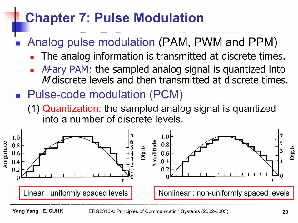
Chapter 7: Pulse ModulationPulse-code modulation (PCM) (continued)(2) Digitization: assign a digit
to each level (one-to-one mapping) so that thewaveform is reducedto a set of digits at thesuccessive sample times.
(3) Code: the digits are expressed in a coded form.Binary code (i.e. a codeusing only two possible pulse levels) is the mostpopular choice.
In a binary code, each pulse can represent one of two possible states, 0 or 1, this basic quantum unit for conveying information is called a binary unit (bit).
(3-bit code)
Transmission of PCM signal
(8 levels)

ERG2310A: Principles of Communication Systems (2002-2003) 31Yang Yang, IE, CUHK
Chapter 7: Pulse ModulationPulse-code modulation (PCM) (continued)
Advantages of PCM systemsIn long-distance communications, PCM signals can be completely regenerated (noise-free) at intermediate repeater stations because all the information is contained in the code. The effects of noise do not accumulate and only the transmission noise between adjacent repeaters need be concerned.Modulating and demodulating circuitry is all digital, thus affording high reliability and stability.Signals may be stored and time scaled efficiently.Efficient codes can be utilized to reduce unnecessary repetition(redundancy) in message. source codingAppropriate coding can reduce the effects of noise and interference. channel coding
Systems making use of the transmission of digitized (i.e. quantized and coded) signals are called PCM systems.

ERG2310A: Principles of Communication Systems (2002-2003) 32Yang Yang, IE, CUHK
Chapter 7: Pulse Modulation
Generation of PCM signals
Method 1: ramp encoder
It uses relatively few precision components. The chief limitation is in the required linearity of the ramp voltage generated. Speed of operation is limited by the speed of the binary counter.
The central operation is that of the analog-to-digital (A/D) converter, which encodes analog signals into digital codes.

ERG2310A: Principles of Communication Systems (2002-2003) 33Yang Yang, IE, CUHK
Chapter 7: Pulse Modulation
Generation of PCM signals (continued)Method 2: feedback encoder
Successive trial voltages are governed by the outcomes of previous decisions (whether the previous trial voltage is greater or less than the level of the analog input).Usually the routine is designed to take one-half the remaining voltage interval for each trial so that the trials converge rapidly.The accuracy depends on the accuracy of the trial voltages. Speed is limited by the speed of “voltage-dividers and switches”. It requires precision components and offers accurate encoding.
Trial voltage

ERG2310A: Principles of Communication Systems (2002-2003) 34Yang Yang, IE, CUHK
Chapter 7: Pulse Modulation
Generation of PCM signals (continued)
Method 3: parallel (or flash) encoder
Each comparator has its own reference. Outputs of all comparators are compared by digital logic circuits to determine the binary code output for each sample value.This parallel encoder can be operated at extremely high speeds at the expense of providing ( ) comparators for m-bit quantization.
121 −=− mn

ERG2310A: Principles of Communication Systems (2002-2003) 35Yang Yang, IE, CUHK
Chapter 7: Pulse Modulation
Suboptimal PCM decoder
Transmission noise is not considered.Resistive dividers are operated by switches that are controlled by the binary code.By weighting the resulting voltage levels in the same proportions as the weights of the code pulses, we reproduce a composite voltage, which reproduces the original quantized voltage.This receiver is simple and widely used in instrumentation systems. It is generally not used on long-distance communication systems, which attempt to maintain as low an error rate as possible.

ERG2310A: Principles of Communication Systems (2002-2003) 36Yang Yang, IE, CUHK
Chapter 7: Pulse ModulationRepresentations of binary PCM code
(Return-to-zero)
(Return-to-bias)
(Alternate Mark Inversion)(Bipolar return-to-zero)
(Non-return-to-zero)

ERG2310A: Principles of Communication Systems (2002-2003) 37Yang Yang, IE, CUHK
Chapter 7: Pulse ModulationRepresentations of binary PCM code (continued)
Return-to-zero (RZ): One ; Zero .Return-to-bias (RB): One ; Zero .Alternate mark inversion (AMI) or bipolar return-to-zero (BRZ):
odd One’s , even One’s ; Zero .Split phase (Manchester): One ; Zero .Split phase (mark): One a phase reversal; Zero no change.Non-return-to-zero (L): One ; Zero .Non-return-to-zero (M): One a level change; Zero no change.Non-return-to-zero (S): One no change; Zero a level change.Delay modulation (Miller code): a “One” is represented by a signal transition at the midpoint of a bit interval. A “Zero” is represented by no transition unless it is followed by another “Zero”, in which case the signal transition occurs at the end of the bit interval.
10 0
1b 0
b
10
10
1 0
b1
b 0b
ERG2310A: Principles of Communication Systems (2002-2003) 38Yang Yang, IE, CUHK
Chapter 7: Pulse Modulation
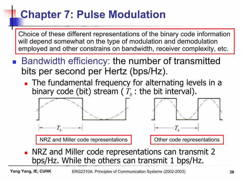
Bandwidth efficiency: the number of transmitted bits per second per Hertz (bps/Hz).
The fundamental frequency for alternating levels in a binary code (bit) stream ( : the bit interval).
NRZ and Miller code representations can transmit 2 bps/Hz. While the others can transmit 1 bps/Hz.
Choice of these different representations of the binary code information will depend somewhat on the type of modulation and demodulation employed and other constrains on bandwidth, receiver complexity, etc.
NRZ and Miller code representations Other code representations
bT bT
bT

ERG2310A: Principles of Communication Systems (2002-2003) 39Yang Yang, IE, CUHK
Chapter 7: Pulse Modulation
Required bandwidth for a binary PCM systemLet be the number of quantization levels.As binary code is used, the number of bits per sample is
, where is the ceil function (e.g. ).Let be the sampling period. The number of bits per second to be sent is .Consider the bandwidth efficiencies for different code representations, the minimum bandwidths required are
Extend the results to the time-multiplexed case, we have
n2log x 52.48.4 ==
≥
TnB 2log
21
TnB 2log
≥
T
n
Tn2log
≥
xx T
nB 2log21
xx T
nB 2log≥
(NRZ & Miller) (RZ, RB, AMI, Manchester & mark)
(NRZ & Miller)(RZ, RB, AMI,
Manchester & mark)
ERG2310A: Principles of Communication Systems (2002-2003) 40Yang Yang, IE, CUHK
Chapter 7: Pulse Modulation
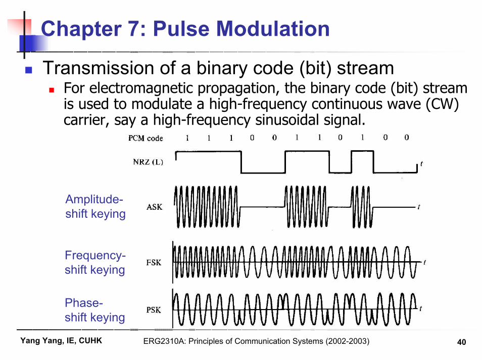
Transmission of a binary code (bit) streamFor electromagnetic propagation, the binary code (bit) stream is used to modulate a high-frequency continuous wave (CW) carrier, say a high-frequency sinusoidal signal.
Amplitude-shift keying
Frequency-shift keying
Phase-shift keying