Embed Size (px)
Citation preview
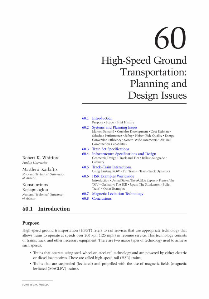
60High-Speed Ground
Transportation:Planning andDesign Issues
60.1 Introduction Purpose • Scope • Brief History
60.2 Systems and Planning IssuesMarket Demand • Corridor Development • Cost Estimate • Schedule Performance • Safety • Noise • Ride Quality • Energy Conversion Efficiency • System-Wide Parameters • Air–Rail Combination Capabilities
60.3 Train Set Specifications60.4 Infrastructure Specifications and Design
Geometric Design • Track and Ties • Ballast–Subgrade • Catenary
60.5 Track–Train InteractionsUsing Existing ROW • Tilt Trains • Train–Track Dynamics
60.6 HSR Examples WorldwideIntroduction • United States: The ACELA Express • France: The TGV • Germany: The ICE • Japan: The Shinkansen (Bullet Train) • Other Examples
60.7 Magnetic Levitation Technology60.8 Conclusions
60.1 Introduction
Purpose
High-speed ground transportation (HSGT) refers to rail services that use appropriate technology thatallows trains to operate at speeds over 200 kph (125 mph) in revenue service. This technology consistsof trains, track, and other necessary equipment. There are two major types of technology used to achievesuch speeds:
• Trains that operate using steel-wheel-on-steel-rail technology and are powered by either electricor diesel locomotives. These are called high-speed rail (HSR) trains.
• Trains that are suspended (levitated) and propelled with the use of magnetic fields (magneticlevitated (MAGLEV) trains).
Robert K. WhitfordPurdue University
Matthew KarlaftisNational Technical University of Athens
Konstantinos KepaptsoglouNational Technical University of Athens
© 2003 by CRC Press LLC
60
-2
The Civil Engineering Handbook, Second Edition
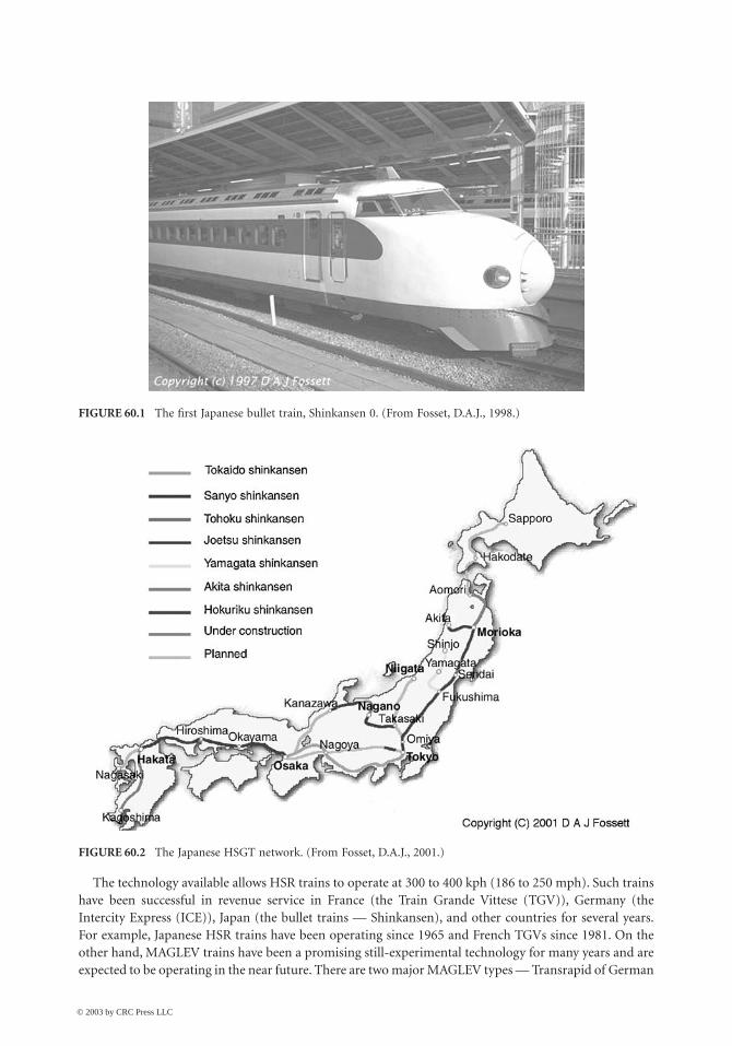
The technology available allows HSR trains to operate at 300 to 400 kph (186 to 250 mph). Such trainshave been successful in revenue service in France (the Train Grande Vittese (TGV)), Germany (theIntercity Express (ICE)), Japan (the bullet trains — Shinkansen), and other countries for several years.For example, Japanese HSR trains have been operating since 1965 and French TGVs since 1981. On theother hand, MAGLEV trains have been a promising still-experimental technology for many years and areexpected to be operating in the near future. There are two major MAGLEV types — Transrapid of German
FIGURE 60.1 The first Japanese bullet train, Shinkansen 0. (From Fosset, D.A.J., 1998.)
FIGURE 60.2 The Japanese HSGT network. (From Fosset, D.A.J., 2001.)
© 2003 by CRC Press LLC
High-Speed Ground Transportation: Planning and Design Issues
60
-3
origin and MLU of Japanese origin — operating experimentally and accommodating small routes.MAGLEV technology is implemented at the moment to connect the Shanghai airport with the city ofShanghai in China. There are also plans of using such technology to connect Shanghai with Beijing [1].
Further, the United States is still remaining skeptical in applying or developing such technology, eitherHSR or MAGLEV, so a great part of this chapter will be devoted to the planning and systems issuesassociated with implementing this technology in the United States. Despite that fact, agencies such asthe Federal Railroad Administration (FRA), Transportation Research Board (TRB), and U.S. Departmentof Transportation (DOT) propose, examine, and fund studies and projects for the implementation ofHSGT in the United States [2–11].
It should be noted also that since HSR and MAGLEV technologies are complex and have many facets,details and advanced information on them are beyond the scope of this chapter.
HSGT has many important civil engineering planning and design considerations. It is calculated thatbetween 65 and 80% of the investment cost is for civil engineering–type facilities (track, right-of-way(ROW), stations, catenaries, bridges, etc.). System requirements that pertain to its introduction to theUnited States are under scrutiny as government and industry still attempt to identify pertinent issuesand problems. Of special concern are those areas of operation, like safety and noise, that are consideredin a different manner by the foreign manufacturers and operators whose history in passenger rail is notparallel to that in the United States.
Scope
A brief history background sets the stage. Section 60.2 discusses pertinent systems issues such as marketdemand, corridor development, cost estimating, scheduling, safety, noise, ride quality, and the like.Section 60.3 presents specifications that pertain to the most well-known types of train sets (TGV andICE), while Section 60.4 discusses the infrastructure. Section 60.5 identifies several track–train interac-tions. Section 60.6 discusses several HSR examples worldwide, and Section 60.7 is devoted to MAGLEVtechnology. A long list of up-to-date references is also provided to help the reader develop a betterunderstanding on HSGT, enhance his or her knowledge, and gather extensive information regarding thesubject.
It should be noted that HSR is often used to refer to the French TGV train [12,14], while Germanshave developed a similar operating train fully competitive to the TGV: the ICE [12,13]. Both types havebeen competitors for implementation in the United States in the past years (for example, in Texas forthe Dallas–Fort Worth–Houston and Dallas–Fort Worth–San Antonio corridors [14–16] and in Floridafor the Miami–Orlando–Tampa corridor [12,17,18]).
Brief History
High-speed trains were introduced in the early 19th century when British engineers developed the steamrailroad locomotives. These locomotives were the beginning of a long era in which varying technologieswere pursued in order to achieve higher speeds coupled with operating and fuel efficiencies. Steampropulsion gave maximum speeds of about 160 kph (100 mph) in the early 20th century. Test speeds of209 kph (130 mph) were attained by using diesel-electric and electric propulsion in the 1930s and 1940s.This change in technology provided slightly improved performance and fuel efficiency, but it was notuntil the 1960s that breakthroughs in suspension, train–track dynamics, and other factors permitted anincrease in train speeds by a factor of 2 or more.
On November 1, 1965, the Japanese introduced, as part of the regular train schedule, a standard-gaugerailway service that reached the maximum speed of 209 kph (130 mph). The average speed of the trainwas 166 kph (103 mph). Although the speed of the train was not a major breakthrough in terms of whathad been previously achieved, the uniqueness was in the dedication of the right-of-way to this system.
The ensuing decade brought much activity in the area of high-speed rail. The Pennsylvania railroaddeveloped the “metro-liners” by placing traction motors on each axle. That train achieved the maximum
© 2003 by CRC Press LLC
60
-4
The Civil Engineering Handbook, Second Edition
speed of 251 kph (156 mph) in Princeton, New Jersey, in May 1967. Only a decade ago, “metro-liner-like” coaches pulled by AEM-7 locomotives operating at speeds of up to 201 kph (125 mph) in revenueservice were the only relatively high-speed rail systems in the United States.
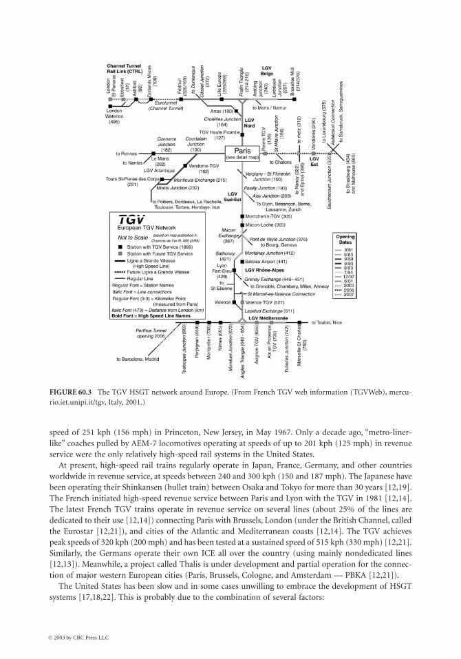
At present, high-speed rail trains regularly operate in Japan, France, Germany, and other countriesworldwide in revenue service, at speeds between 240 and 300 kph (150 and 187 mph). The Japanese havebeen operating their Shinkansen (bullet train) between Osaka and Tokyo for more than 30 years [12,19].The French initiated high-speed revenue service between Paris and Lyon with the TGV in 1981 [12,14].The latest French TGV trains operate in revenue service on several lines (about 25% of the lines arededicated to their use [12,14]) connecting Paris with Brussels, London (under the British Channel, calledthe Eurostar [12,21]), and cities of the Atlantic and Mediterranean coasts [12,14]. The TGV achievespeak speeds of 320 kph (200 mph) and has been tested at a sustained speed of 515 kph (330 mph) [12,21].Similarly, the Germans operate their own ICE all over the country (using mainly nondedicated lines[12,13]). Meanwhile, a project called Thalis is under development and partial operation for the connec-tion of major western European cities (Paris, Brussels, Cologne, and Amsterdam — PBKA [12,21]).
The United States has been slow and in some cases unwilling to embrace the development of HSGTsystems [17,18,22]. This is probably due to the combination of several factors:
FIGURE 60.3 The TGV HSGT network around Europe. (From French TGV web information (TGVWeb), mercu-rio.iet.unipi.it/tgv, Italy, 2001.)
© 2003 by CRC Press LLC
High-Speed Ground Transportation: Planning and Design Issues
60
-5
• The love of Americans for the automobile
• The advances of the airline industry and the economic power of airline companies (which isquestionable after the 2001 terrorist acts in the United States)
• The size of the U.S. landmass in conjunction with its population density
• The skepticism of generating enough demand for a profitable venture in any but the highestpopulation corridors
• The lack of a passenger railroad culture
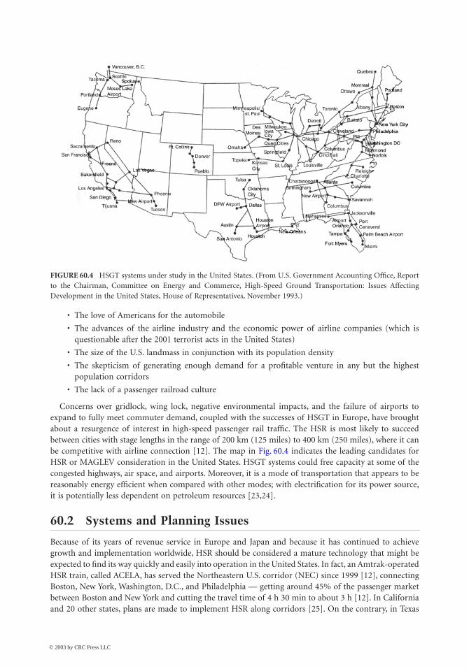
Concerns over gridlock, wing lock, negative environmental impacts, and the failure of airports toexpand to fully meet commuter demand, coupled with the successes of HSGT in Europe, have broughtabout a resurgence of interest in high-speed passenger rail traffic. The HSR is most likely to succeedbetween cities with stage lengths in the range of 200 km (125 miles) to 400 km (250 miles), where it canbe competitive with airline connection [12]. The map in Fig. 60.4 indicates the leading candidates forHSR or MAGLEV consideration in the United States. HSGT systems could free capacity at some of thecongested highways, air space, and airports. Moreover, it is a mode of transportation that appears to bereasonably energy efficient when compared with other modes; with electrification for its power source,it is potentially less dependent on petroleum resources [23,24].
60.2 Systems and Planning Issues
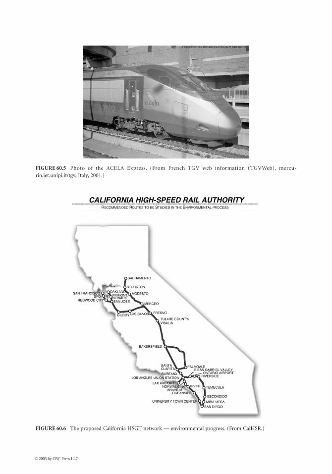
Because of its years of revenue service in Europe and Japan and because it has continued to achievegrowth and implementation worldwide, HSR should be considered a mature technology that might beexpected to find its way quickly and easily into operation in the United States. In fact, an Amtrak-operatedHSR train, called ACELA, has served the Northeastern U.S. corridor (NEC) since 1999 [12], connectingBoston, New York, Washington, D.C., and Philadelphia — getting around 45% of the passenger marketbetween Boston and New York and cutting the travel time of 4 h 30 min to about 3 h [12]. In Californiaand 20 other states, plans are made to implement HSR along corridors [25]. On the contrary, in Texas
FIGURE 60.4 HSGT systems under study in the United States. (From U.S. Government Accounting Office, Reportto the Chairman, Committee on Energy and Commerce, High-Speed Ground Transportation: Issues AffectingDevelopment in the United States, House of Representatives, November 1993.)
© 2003 by CRC Press LLC
60
-6
The Civil Engineering Handbook, Second Edition
FIGURE 60.5 Photo of the ACELA Express. (From French TGV web information (TGVWeb), mercu-rio.iet.unipi.it/tgv, Italy, 2001.)
FIGURE 60.6 The proposed California HSGT network — environmental progress. (From CalHSR.)
© 2003 by CRC Press LLC
High-Speed Ground Transportation: Planning and Design Issues
60
-7
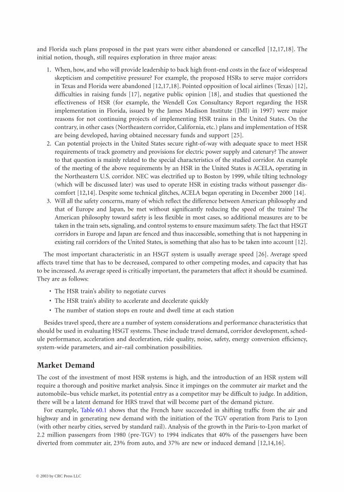
and Florida such plans proposed in the past years were either abandoned or cancelled [12,17,18]. Theinitial notion, though, still requires exploration in three major areas:
1. When, how, and who will provide leadership to back high front-end costs in the face of widespreadskepticism and competitive pressure? For example, the proposed HSRs to serve major corridorsin Texas and Florida were abandoned [12,17,18]. Pointed opposition of local airlines (Texas) [12],difficulties in raising funds [17], negative public opinion [18], and studies that questioned theeffectiveness of HSR (for example, the Wendell Cox Consultancy Report regarding the HSRimplementation in Florida, issued by the James Madison Institute (JMI) in 1997) were majorreasons for not continuing projects of implementing HSR trains in the United States. On thecontrary, in other cases (Northeastern corridor, California, etc.) plans and implementation of HSRare being developed, having obtained necessary funds and support [25].
2. Can potential projects in the United States secure right-of-way with adequate space to meet HSRrequirements of track geometry and provisions for electric power supply and catenary? The answerto that question is mainly related to the special characteristics of the studied corridor. An exampleof the meeting of the above requirements by an HSR in the United States is ACELA, operating inthe Northeastern U.S. corridor. NEC was electrified up to Boston by 1999, while tilting technology(which will be discussed later) was used to operate HSR in existing tracks without passenger dis-comfort [12,14]. Despite some technical glitches, ACELA began operating in December 2000 [14].
3. Will all the safety concerns, many of which reflect the difference between American philosophy andthat of Europe and Japan, be met without significantly reducing the speed of the trains? TheAmerican philosophy toward safety is less flexible in most cases, so additional measures are to betaken in the train sets, signaling, and control systems to ensure maximum safety. The fact that HSGTcorridors in Europe and Japan are fenced and thus inaccessible, something that is not happening inexisting rail corridors of the United States, is something that also has to be taken into account [12].
The most important characteristic in an HSGT system is usually average speed [26]. Average speedaffects travel time that has to be decreased, compared to other competing modes, and capacity that hasto be increased. As average speed is critically important, the parameters that affect it should be examined.They are as follows:
• The HSR train’s ability to negotiate curves
• The HSR train’s ability to accelerate and decelerate quickly
• The number of station stops en route and dwell time at each station
Besides travel speed, there are a number of system considerations and performance characteristics thatshould be used in evaluating HSGT systems. These include travel demand, corridor development, sched-ule performance, acceleration and deceleration, ride quality, noise, safety, energy conversion efficiency,system-wide parameters, and air–rail combination possibilities.
Market Demand
The cost of the investment of most HSR systems is high, and the introduction of an HSR system willrequire a thorough and positive market analysis. Since it impinges on the commuter air market and theautomobile–bus vehicle market, its potential entry as a competitor may be difficult to judge. In addition,there will be a latent demand for HRS travel that will become part of the demand picture.
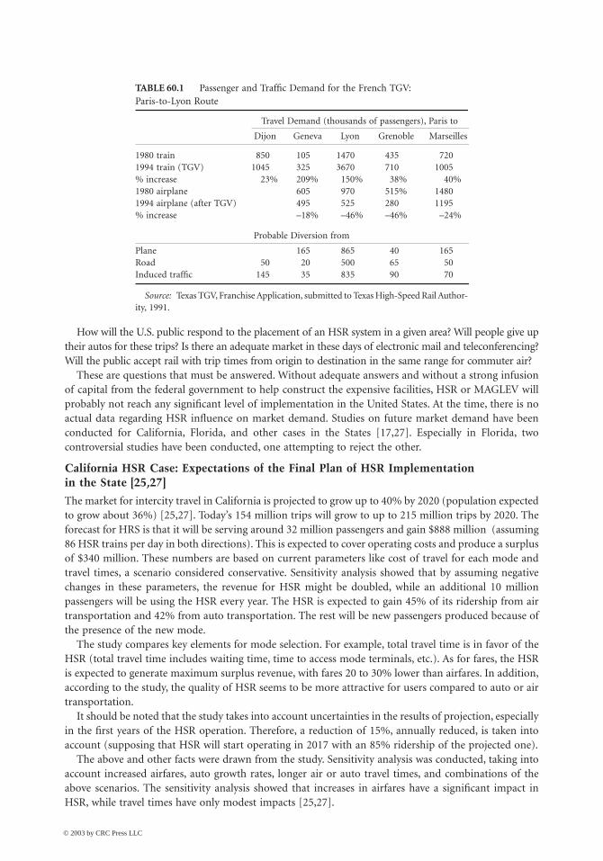
For example, Table 60.1 shows that the French have succeeded in shifting traffic from the air andhighway and in generating new demand with the initiation of the TGV operation from Paris to Lyon(with other nearby cities, served by standard rail). Analysis of the growth in the Paris-to-Lyon market of2.2 million passengers from 1980 (pre-TGV) to 1994 indicates that 40% of the passengers have beendiverted from commuter air, 23% from auto, and 37% are new or induced demand [12,14,16].
© 2003 by CRC Press LLC
60
-8
The Civil Engineering Handbook, Second Edition
How will the U.S. public respond to the placement of an HSR system in a given area? Will people give uptheir autos for these trips? Is there an adequate market in these days of electronic mail and teleconferencing?Will the public accept rail with trip times from origin to destination in the same range for commuter air?
These are questions that must be answered. Without adequate answers and without a strong infusionof capital from the federal government to help construct the expensive facilities, HSR or MAGLEV willprobably not reach any significant level of implementation in the United States. At the time, there is noactual data regarding HSR influence on market demand. Studies on future market demand have beenconducted for California, Florida, and other cases in the States [17,27]. Especially in Florida, twocontroversial studies have been conducted, one attempting to reject the other.
California HSR Case: Expectations of the Final Plan of HSR Implementation in the State [25,27]
The market for intercity travel in California is projected to grow up to 40% by 2020 (population expectedto grow about 36%) [25,27]. Today’s 154 million trips will grow to up to 215 million trips by 2020. Theforecast for HRS is that it will be serving around 32 million passengers and gain $888 million (assuming86 HSR trains per day in both directions). This is expected to cover operating costs and produce a surplusof $340 million. These numbers are based on current parameters like cost of travel for each mode andtravel times, a scenario considered conservative. Sensitivity analysis showed that by assuming negativechanges in these parameters, the revenue for HSR might be doubled, while an additional 10 millionpassengers will be using the HSR every year. The HSR is expected to gain 45% of its ridership from airtransportation and 42% from auto transportation. The rest will be new passengers produced because ofthe presence of the new mode.
The study compares key elements for mode selection. For example, total travel time is in favor of theHSR (total travel time includes waiting time, time to access mode terminals, etc.). As for fares, the HSRis expected to generate maximum surplus revenue, with fares 20 to 30% lower than airfares. In addition,according to the study, the quality of HSR seems to be more attractive for users compared to auto or airtransportation.
It should be noted that the study takes into account uncertainties in the results of projection, especiallyin the first years of the HSR operation. Therefore, a reduction of 15%, annually reduced, is taken intoaccount (supposing that HSR will start operating in 2017 with an 85% ridership of the projected one).
The above and other facts were drawn from the study. Sensitivity analysis was conducted, taking intoaccount increased airfares, auto growth rates, longer air or auto travel times, and combinations of theabove scenarios. The sensitivity analysis showed that increases in airfares have a significant impact inHSR, while travel times have only modest impacts [25,27].
TABLE 60.1 Passenger and Traffic Demand for the French TGV: Paris-to-Lyon Route
Travel Demand (thousands of passengers), Paris to
Dijon Geneva Lyon Grenoble Marseilles
1980 train 850 105 1470 435 7201994 train (TGV) 1045 325 3670 710 1005% increase 23% 209% 150% 38% 40%1980 airplane 605 970 515% 14801994 airplane (after TGV) 495 525 280 1195% increase –18% –46% –46% –24%
Probable Diversion from
Plane 165 865 40 165Road 50 20 500 65 50Induced traffic 145 35 835 90 70
Source: Texas TGV, Franchise Application, submitted to Texas High-Speed Rail Author-ity, 1991.
© 2003 by CRC Press LLC
High-Speed Ground Transportation: Planning and Design Issues
60
-9
The major conclusion of the study is that, despite that HSR will not be the dominant mode of intercitytransportation in most cases, the fact that it will be economically viable makes it applicable to California.
Florida HSR Case: Two Opposing Studies
Since 1991, the Florida DOT (FDOT) has initiated studies of implementing HSR in Florida, with thepotential of partial public funding [17,18]. In 1995, FDOT asked for proposals by private companies forfinancing, operating, and building an HSR system along the Miami–Orlando–Tampa corridor. Fivecompanies offered proposals, from which Florida Overland Express (FOX) had the winning proposal,mainly because of its better financing plans and the fact that the company fulfilled the requirementsregarding environment, safety, technology, etc. set by FDOT.
FOX had developed an analysis in 1995 to support its proposal along the Miami–Orlando–Tampacorridor, including ridership, building and operating costs, and financing of the project. The ridershipanalysis was revised by FOX and FDOT later in 1998, only to find increased projected ridership.
In 1997, a report prepared by Wendell Cox Consultancy [17] and issued by the James Madison Institutequestioned the accuracy and results of the FOX market analysis, concluding that HSR would carry fewerpassengers than the FOX market analysis expected and would cost more and expose taxpayers becauseof that. The Cox analysis asserted that the ridership forecast was incorrect (unreliably high for the HSRpart), as were the air and HSR fare forecasts. The Cox analysis concluded that the FOX project had anincorrect market analysis (in terms of forecasting) and, thus, its financing plan would not be achievableand would be costly to taxpayers. Comparisons with FRA-forecasted numbers for ridership and fares andthe economic condition of HSR companies in Europe were additional facts in the Cox analysis. The resultof the confrontation was in favor of the Wendell Cox Consultancy study; in 1998 the governor of Floridacancelled the FOX project.
Chicago–Milwaukee: Twin Cities Corridor Study [28]
For the Twin Cities corridor study, fairly conservative demand models were developed, examining threescenarios (125-, 186-, and 300-mph systems). It was revealed that the 125-mph option offers the bestfinancial return, the fewest environmental costs, and the highest economic benefit per dollar invested,which would be relevant to a public sector capital-constrained investment program. While the neteconomic benefits are not quite as high as with the 185- and 300-mph options, the level of benefit issubstantial. The economic benefits achieved by the 125-mph option are 80% of those achieved by the185-mph technology and 94% of those achieved by the 300-mph technology. The 185-mph technology(TGV) has a good financial return and the highest net economic benefits, but it suffers from the highestenvironmental costs because of the severance problems associated with its new right-of-way. The 300-mph technology (MAGLEV) provides good economic benefits but has only marginal financial perfor-mance due to its substantial capital costs. What is surprising is that the 300-mph option performs as wellas it does, given its huge capital costs.
Corridor Development
The corridor for HSR will require either an upgrade of existing track or new land acquisition coupledwith the construction of straighter track, built with the stability in alignment required for these speeds.This may not be so easy, since the corridor will bisect farmers’ fields and create dead ends for many ruralroads. The corridor would also require rerouting of utility service lines such as gas, water, sewer, telephone,and electricity.
At the speeds of the HSR, grade separation is necessary, so overpasses and underpasses will be requiredin many areas. For some farms it may be necessary to put an access tunnel under the roadbed in orderfor the farmer to get from his fields on one side of the track to those on the other. For example, the 458 kmbetween Fort Worth–Dallas and Houston is estimated to require 270 bridges over creeks, rivers, highways,and other railroads, plus about 25,000 m of elevated track, mostly in the urban areas. Also needed wouldbe about 145 culverts (10 ¥ 10 ¥ 150 ft) for drainage and access along the same right-of-way [15].
© 2003 by CRC Press LLC
60
-10
The Civil Engineering Handbook, Second Edition
Small towns also pose problems to an HSR corridor. If the use of the present ROW is suggested, muchof that ROW passes through small towns and other lightly populated areas. The choice and the placementof the corridor, the approach to tunnels, and the design of other depressed or elevated ROWs aroundthese towns may significantly increase the cost of the investment. Most of these towns will not have astation, since the train won’t be able to stop frequently in order to take advantage of the higher peakspeed. Therefore, the economic development aspects, which classically occur around stations, will nottake place and the towns may see the HSR only as a nuisance.
Entering large urban areas may be easy or difficult, depending on the existing roadbed. The TGV,operating at reduced speeds, uses existing track for entry and exit of Paris and Lyon [12,21].
The corridor chosen may require some tradeoff between the cost of wetlands remediation (if wetlandsare in the path of the HSR corridor) and alternate routes that require less or no mitigation.
There is no doubt that access of ROW for a corridor, whether through procurement, eminent domain,or condemnation, must occur very early in the project — well before any construction is due to begin.With the corridor disruption or “severance” of farms or landscape, the HSR will face the usual uphillbattle from those who do not want the railroad. The “Not in My Backyard” (NIMBY) syndrome will inall likelihood be very prevalent.
An example of a corridor study for HSGT implementation is the Chicago–St. Louis High Speed RailStudy, completed in August 2000 by the U.S. DOT, FHWA, FRA, and Illinois DOT [28]. For the corridorstudy, two major alternatives were examined: (1) the “do-nothing” alternative, where the existing Amtrakservice would remain with the regular maintenance and rehabilitation actions on the corridor and (2) anHSR train implementation as a more viable solution, compared to air and auto travel. The HSR wouldoperate at speeds of 110 and 125 mph and would consist of 8 round trips per day, every 2 hours, witha travel time of around 3.5 h. Existing tracks would be used and, in addition, new tracks would beconstructed to facilitate the HSR performance. Three different alignments were proposed for the HSRimplementation. Also, different types of train sets (electric or diesel) and different operating speeds wereexamined; 110 mph was chosen as the most cost effective. The evaluation of the different alternativesexamined land use and farmland; displacements; and effects on employment around the corridor, onwater and natural resources, and on wetlands and floodplains, as well as effects on cultural resources,waste, and grade crossings. Special care was taken for the accommodation of grade crossings and effectswhen crossing small cities. Also, unresolved problems remained, concerning other agencies as well, forthe disposal of waste, the treatment of historical properties, air quality issues, etc.
Cost Estimate
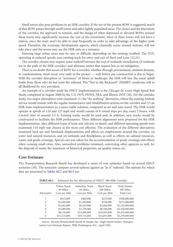
The Transportation Research Board has developed a series of cost estimates based on several HSGTscenarios [30]. The scenarios compare several options against an “as is” railroad. The options for whichdata are presented in Tables 60.2 and 60.3 are:
TABLE 60.2 Estimates for Six Alternatives of HSGT: 300-Mile Corridor
Alternative
Urban Track,40 Miles,
Cost per Mile
Suburban Track60 Miles,
Cost per Mile
Rural Track,200 Miles,
Cost per Mile
Total System,300 Miles,Total Cost
1 $915,000 $400,000 $235,000 $108,000,0002 $1,660,000 $1,000,000 $740,000 $275,000,0003 $7,645,000 $6,410,000 $5,260,000 $1,742,000,0004 $7,680,000 $7,370,000 $8,340,000 $2.418,000,0005 $8,110,000 $14,490,000 $10,495,000 $3,293,000,0006 $31,115,000 $19,715,000 $14,055,000 $5,239,000,000
Source: Parsons Brinckerhoff Quade & Quade, Inc., High-Speed Surface Transpor-tation Cost Estimate Report, TRB, Washington, D.C., April 1991.
© 2003 by CRC Press LLC
High-Speed Ground Transportation: Planning and Design Issues
60
-11
1. “As is” railroad requiring a typical class-3 track to be upgraded with the addition of block signalingand passing sidings to permit 125-kph (79-mph) passenger service.
2. Low ROW/capital investment strategy with top speeds of 175 kph (110 mph) and upgrades in trackand cab signaling. ROW width sufficient for second track and major rehabilitation at stations.
3. Intercity/shared ROW would have top speeds of 200 kph (125 mph) with electric propulsion, afull double track, and concrete ties maintained to FRA class-6 standards. All high-speed crossingswould be grade separated.
4. Intercity/shared ROW/new bypass segment with one to several bypass segments with track geometryand signaling to permit top speed on the bypasses of 240 kph (150 mph).
5. The TGV approach with trains operating mostly on new ROW dedicated to the TGV with top-speed operation in the 290- to 320-kph (180- to 200-mph) range.
6. New technology using MAGLEV concepts with a top speed of 500 kph (320 mph).
The TRB presents many assumptions on which the above numbers are based. However, for the purposeof planning, these numbers should be sufficient for preliminary estimation. The costs include land, ROWpreparation, utilities relocation, track construction, realignments, grade separations and enclosures,fencing, electrification, signaling, undergrade bridges, overhead bridges, tunnels, terminals, beltwaystations, O&M, central control administration, and train sets. The assumptions are given in sufficientdetail so that a quick estimate can be made. The costs for a 500-km (300-mile) system with 67 km(40 miles) of urban land, 100 km (60 miles) of suburban land, and 333 km (200 miles) of rural land arepresented. The average cost for the TGV (option 5) is about $6.84 million per kilometer ($11 millionper mile) [30,31].
Schedule Performance
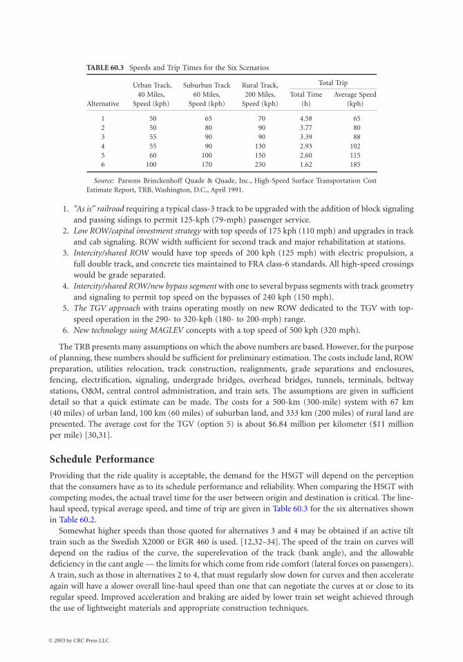
Providing that the ride quality is acceptable, the demand for the HSGT will depend on the perceptionthat the consumers have as to its schedule performance and reliability. When comparing the HSGT withcompeting modes, the actual travel time for the user between origin and destination is critical. The line-haul speed, typical average speed, and time of trip are given in Table 60.3 for the six alternatives shownin Table 60.2.
Somewhat higher speeds than those quoted for alternatives 3 and 4 may be obtained if an active tilttrain such as the Swedish X2000 or EGR 460 is used. [12,32–34]. The speed of the train on curves willdepend on the radius of the curve, the superelevation of the track (bank angle), and the allowabledeficiency in the cant angle — the limits for which come from ride comfort (lateral forces on passengers).A train, such as those in alternatives 2 to 4, that must regularly slow down for curves and then accelerateagain will have a slower overall line-haul speed than one that can negotiate the curves at or close to itsregular speed. Improved acceleration and braking are aided by lower train set weight achieved throughthe use of lightweight materials and appropriate construction techniques.
TABLE 60.3 Speeds and Trip Times for the Six Scenarios
Alternative
Urban Track,40 Miles,
Speed (kph)
Suburban Track60 Miles,
Speed (kph)
Rural Track,200 Miles,
Speed (kph)
Total Trip
Total Time(h)
Average Speed(kph)
1 50 65 70 4.58 652 50 80 90 3.77 803 55 90 90 3.39 884 55 90 130 2.93 1025 60 100 150 2.60 1156 100 170 230 1.62 185
Source: Parsons Brinckenhoff Quade & Quade, Inc., High-Speed Surface Transportation CostEstimate Report, TRB, Washington, D.C., April 1991.
© 2003 by CRC Press LLC
60
-12
The Civil Engineering Handbook, Second Edition
The number of stations and the dwell time in each station will also affect the overall time of travelbetween two points. Analysis of the TGV on one 400-km (250-mile) route with a maximum line-haultrain speed of 300 kph (186 mph) and stops at four intermediate stations, each with a dwell time of3 min, had 118 min of elapsed time from doors closing at the origin to opening at the final destination.The average speed was 204 kph (127 mph).
Safety
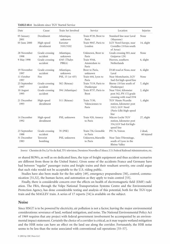
The potential severity of higher-speed accidents can be offset by such factors as dedicated right-of-way,fully fenced corridors, automatic train control, and ROW maintenance — all geared to reduce the overallrisk. A large part of the research regarding HSGT systems has focused on safety issues [35–38]. Many ofthese issues deal with crash tests and car designs that will minimize bodily injuries in case of a crash.The existing HSGT systems in Europe are operating at a level of safety that is better than that ofconventional rail technology. The excellent system maintenance, highly automated train control, dedi-cated ROW, and fencing around the tracks have led to an amazingly safe accident record. For example,the Japanese Shinkansen line has had no fatal accidents in the past 18 years while having transportedapproximately 2 billion passengers [24,43]. The same applies to the TGV: while operating at high speeds,no fatal accidents have happened since it began service in 1981. In fact, within the last 20 years of TGVservice, only 11 incidents have occurred, the most important of which occurred in the conventional lines,where the speeds were lower and any conventional train had the same chances of facing such an incident.Table 60.4 shows the incidents and the dates they occurred. The most serious accident concerning anHSR train within the last 20 years of HSGT operation in Europe happened in 1998, when a German ICE1 HSR-type train derailed on a highway bridge abutment at a speed of 200 kph and caused the bridgeto collapse, as well. The accident caused the death of 88 passengers and injury of at least another 100and forced the German government to operate its ICE trains at lower speeds for a long period [12,13].The cause of the crash was the cracking of a defective wheel [12,13].
Higher-speed operations on existing lines pose an especially difficult problem. The track, ballast, andgeometry are all designed to accommodate lower speeds. There will certainly be increased risk associatedwith the use of this track in high-speed operation. In fact, the use of an existing ROW such as in theNortheast corridor is what happened in the United States. With the large amounts of capital needed, itis clear that until the federal government decides to fund dedicated ROWs, the upgrading and increaseduse of existing ROWs will be the direction higher-speed rail takes in the United States (Next GenerationRail, Accelerail, Incremental Rail, or whatever one wants to call it). With this use comes the need to assesshow ROW and equipment design, signal systems, onboard and wayside detectors of various sorts, gradecrossings, ROW security, etc. contribute to enhancing the overall safety risk, given the accident severitypotential that inherently increases with speed. Such progress is achieved by using other system elementsto control risk to the same or lower levels than is currently accepted by the riding public [44,45]. TheTRB IDEA program suggests several areas of study regarding the safety of HSGT [5], focused mainly onupgrading the existing ROWs.
This leads to a careful design of an onboard monitoring system that will automatically slow a trainthat is starting to hunt. The elements with automation will include accelerometers to detect the onset oftruck hunting, bearing temperature monitors, brake system sensors, various wayside detectors, etc. [5,7].
As speeds increase above 200 kph (125 mph), dynamic force control is a key factor in maintainingsafety of operation. New inspection methodologies to move from the currently accepted static geometry(even if loaded) measurements to more dynamic real-time monitoring of equipment forces (wheel) andthe track response and interaction (rail) are needed for the HSR. The whole issue of maintaining trackfor ride comfort versus minimum track geometry standards must be addressed [47,48].
Lighter weight but stronger materials will be required (one key to the success of TGV and ICE), whileit will be appropriate to maintain or reduce, not increase, axle loads. Thus, given the United States’ needto design for different collision scenarios (mixed freight and passenger operations), the challenge to beinnovative will be even greater. (Even though the TGV and ICE trains in some cases do operate on existing
© 2003 by CRC Press LLC
High-Speed Ground Transportation: Planning and Design Issues
60
-13
or shared ROWs, as well as on dedicated lines, the type of freight equipment and thus accident scenariosare different from those in the United States). Given some of the accidents France and Germany havehad between “regular” passenger trains and freight trains and their resultant severity, one could arguethat such risks would not be acceptable to the U.S. riding public.
Studies have also been made for the fire safety [49], emergency preparedness [50], control, commu-nication [51,52], the human factor, and automation as they apply to train control [53].
Finally, there is considerable concern over the effects on health of electromagnetic field (EMF) radi-ation. The FRA, through the Volpe National Transportation Systems Centre and the EnvironmentalProtection Agency, has done considerable testing and analysis of this potential, both for the TGV-typetrain and the MAGLEV train. A series of 17 reports [54] is available on the subject.
Noise
Since HSGT is to be powered by electricity, air pollution is not a factor, leaving the major environmentalconsiderations: severance of land, wetland mitigation, and noise. The National Environmental Policy Actof 1969 requires that any project with federal government involvement be accompanied by an environ-mental impact statement. Certainly the choice of a corridor is critical, as it may require wetland mitigationand the HSR noise can have an effect on the land use along the corridor. Fortunately, the HSR noiseseems to be less than the noise associated with conventional rail operations [55–57].
TABLE 60.4 Incidents since TGV Started Service
Date Cause Train Set Involved Service Location Injuries
05 January 2001
Derailment Atlantique, unknown
Train 8720, Brest to Paris
Standard line near Laval (Mayenne)
None
05 June 2000 High-speed derailment
Eurostar 3101/3102
Train 9047, Paris to London
LGV Nord Europe, near Croisilles (10 km south of Arras)
14, slight
28 November 1998
Grade-crossing accident
Atlantique, unknown
Unknown, Brest to Paris
Grade crossing 303, near Guipavas (29)
None
9 May 1998 Grade-crossing accident
4345 (Thalys PBKA)
Train 9344, Amsterdam to Paris
Hoeven, southern Netherlands
6, slight
19 November 1997
Grade-crossing accident
Atlantique, unknown
Brest to Paris, unknown
D140 road at Neau, near Laval
6, slight
11 October 1997
Fire PSE, 15 (or 45?) Train 644, Lyon to Paris
Near Montchanin, LGV Sud-Est high-speed line
None
25 September 1997
Grade-crossing accident
502 (Réseau) Train 7119, Paris to Dunkerque
Bierne (10 km south of Dunkerque)
7, slight
10 August 1995
Grade-crossing accident
394 (Atlantique) Train 8737, Paris to Brest
Near Vitré, kilometer post 342, PN 172 grade crossing with road D34
2, slight
21 December 1993
High-speed derailment
511 (Réseau) Train 7150, Valenciennes to Paris
TGV Haute Picardie station, kilometer post 110.5, LGV Nord (Paris-Lille) high-speed line
1, slight
14 December 1992
High-speed derailment
PSE, unknown Train 920, Annecy to Paris
Mâcon-Loché TGV station, kilometer post 334, LGV Sud-Est high- speed line
27, slight
23 September 1988
Grade-crossing accident
70 (PSE) Train 736, Grenoble to Paris
PN 74, Voiron 2 dead, 60 injured
31 December 1983
Terrorist bombing
PSE, unknown Unknown, Marseille to Paris
Near Tain-l’Hermitage, south of Lyon in the Rhône Valley
Source: Chemins de Fer, La Vie du Rail, TF1 television, Dernieres Nouvelles d’Alsace, U.S. Federal Railroad Administration, etc.
© 2003 by CRC Press LLC

60
-14
The Civil Engineering Handbook, Second Edition
Given that noise increases with speed, due to the high aerodynamic component, the need for eitherpassive barriers or active noise canceling systems becomes apparent [46].
The major noise sources in diesel operations are the engine and the interaction of the steel wheel onsteel rail. The noise levels from pre-1987 diesel locomotives vary from 67 dBA at idle to 89 dBA at fullthrottle when standing 100 ft from the locomotive [55]. The wheel–rail noise levels vary dramaticallyaccording to the type of wheel and track structure. Most irritating is the track squeal resulting fromlateral sliding of the wheels. Wheel–rail noise is usually computed as a function of the speed of the train.
Likewise, the noise experienced by rapid rail transit is attributed to the electric engine, which is muchquieter than its diesel-driven counterpart and the rail–wheel interaction. The noise level for theSan Francisco Bay Area Rapid Transit System (BART) at 60 mph is approximately 83 dBA 50 ft from thetrain; the corresponding diesel noise is 97 dBA [55].
The Japanese Shinkansen has been in operation since 1964 and has provided much noise data. Thenoise level measured at 15 ft from the train varies from 62 dBA at 118 mph to 76 dBA at 124 mph. TheFrench TGV showed noise somewhat higher when operating on its Paris–Lyon route. However, 72 dBAwas exceeded at only three homes along the route, and the maximum noise measure 82 ft from the trainwas 97 dBA. The German ICE reported noise levels of 86 dBA at 11.5 ft from the train travelling 124 mphand 93 dBA at 186 mph.
Care in design will keep the noise at these relatively low levels. With noise barriers provided by eithertrees and shrubs, constructed walls or depressed track, the noise of the HSGT should be well below anysound levels that would pose an annoyance to neighbors.
Ride Quality
In addition to the stress on performance, the consumers will ride the HSGT only if, as passengers, theyperceive it to be comfortable. Thus, ride quality as experienced in the seat design and in the amenitiesis quite important. Although ride quality is subjective in nature, the train set appearance, both interiorand exterior, lighting, sound levels, airflow, and temperature determine the appeal. Most of the Europeantrains also provide places for small meetings, phone and fax service, special workspaces including com-puter hookups, and real-time trip-related status information.
Physical ride quality is determined by track design and alignment, car body motion, and the designof the passenger seats. The track input comes from the track itself: is the rail continuous and is it aligned?Most of the high-speed lines maintain track to achieve lateral and vertical forces and acceleration levelslow enough to assure good ride quality. At present International Standards Organization (ISO) standardsfor ride quality do exist. From a vehicle point of view, dynamically balanced wheel sets, wheel profile,and low unsprung mass are considered the strongest influences for best ride quality [58]. Low unsprungmass is essential for truck stability, while the suspension must be designed to minimize lateral and verticalmovements of the car body. Wheel profile is important in maintaining safe levels of wheel–rail interactionforces to ensure a smooth and comfortable ride. In summary, ride comfort is very subjective, and eachrailway authority develops its own criteria.
So important is riding quality that sensors and a computer are employed on many trains to give a real-time measure of ride quality and to make adjustments or signal the engineer as necessary. Furthermore,these data may be used to indicate portions of the track for special maintenance. Such a maintenancephilosophy dramatically reduces the likelihood of encountering unsafe levels. The TGV uses truck-mounted accelerometers to detect truck hunting and requires immediate reduction in speed if suchhunting is detected.
Energy Conversion Efficiency
Energy use by the train is important, and one of the goals of the HGST systems is to conserve energy tominimize operating cost. Energy efficiency is a function of the propulsion system, gearing, and train setdesign. The Federal Railroad Administration, through the Improved Passenger Equipment Evaluation
© 2003 by CRC Press LLC
High-Speed Ground Transportation: Planning and Design Issues
60
-15
Program (IPEEP), found that increased train weight leads to increased energy consumption, in the rangeof 0.06 to 0.08 watt hours/seat-km ton [59].
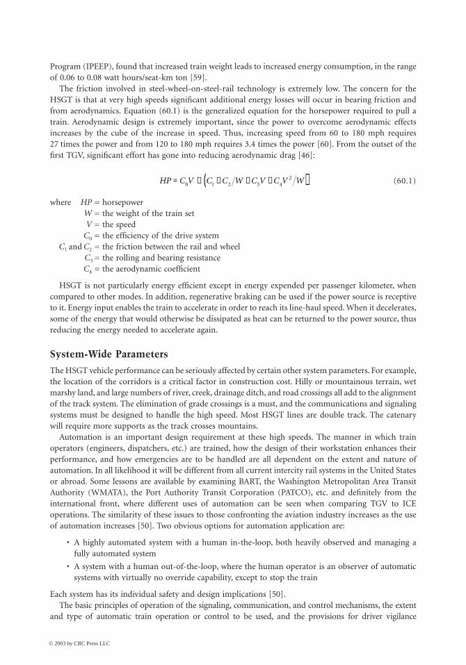
The friction involved in steel-wheel-on-steel-rail technology is extremely low. The concern for theHSGT is that at very high speeds significant additional energy losses will occur in bearing friction andfrom aerodynamics. Equation (60.1) is the generalized equation for the horsepower required to pull atrain. Aerodynamic design is extremely important, since the power to overcome aerodynamic effectsincreases by the cube of the increase in speed. Thus, increasing speed from 60 to 180 mph requires27 times the power and from 120 to 180 mph requires 3.4 times the power [60]. From the outset of thefirst TGV, significant effort has gone into reducing aerodynamic drag [46]:
(60.1)
where HP = horsepowerW = the weight of the train setV = the speed
C0 = the efficiency of the drive systemC1 and C2 = the friction between the rail and wheel
C3 = the rolling and bearing resistanceC4 = the aerodynamic coefficient
HSGT is not particularly energy efficient except in energy expended per passenger kilometer, whencompared to other modes. In addition, regenerative braking can be used if the power source is receptiveto it. Energy input enables the train to accelerate in order to reach its line-haul speed. When it decelerates,some of the energy that would otherwise be dissipated as heat can be returned to the power source, thusreducing the energy needed to accelerate again.
System-Wide Parameters
The HSGT vehicle performance can be seriously affected by certain other system parameters. For example,the location of the corridors is a critical factor in construction cost. Hilly or mountainous terrain, wetmarshy land, and large numbers of river, creek, drainage ditch, and road crossings all add to the alignmentof the track system. The elimination of grade crossings is a must, and the communications and signalingsystems must be designed to handle the high speed. Most HSGT lines are double track. The catenarywill require more supports as the track crosses mountains.
Automation is an important design requirement at these high speeds. The manner in which trainoperators (engineers, dispatchers, etc.) are trained, how the design of their workstation enhances theirperformance, and how emergencies are to be handled are all dependent on the extent and nature ofautomation. In all likelihood it will be different from all current intercity rail systems in the United Statesor abroad. Some lessons are available by examining BART, the Washington Metropolitan Area TransitAuthority (WMATA), the Port Authority Transit Corporation (PATCO), etc. and definitely from theinternational front, where different uses of automation can be seen when comparing TGV to ICEoperations. The similarity of these issues to those confronting the aviation industry increases as the useof automation increases [50]. Two obvious options for automation application are:
• A highly automated system with a human in-the-loop, both heavily observed and managing afully automated system
• A system with a human out-of-the-loop, where the human operator is an observer of automaticsystems with virtually no override capability, except to stop the train
Each system has its individual safety and design implications [50].The basic principles of operation of the signaling, communication, and control mechanisms, the extent
and type of automatic train operation or control to be used, and the provisions for driver vigilance
HP C V C C W C V C V W= ¥ + + +( )0 1 2 3 42
© 2003 by CRC Press LLC
60-16 The Civil Engineering Handbook, Second Edition
monitoring and override are important but beyond the scope of this handbook. It also should be notedthat there is a recent effort in Europe to keep the same standards and types in automation technology overall European HSGT lines so that HSGT train sets from different origins can operate everywhere in Europe.
Air–Rail Combination Capabilities
It is a fact that there should be intermodality between air and rail so that passenger traffic in shortdistances can be diverted from air to rail transportation, freeing up airline capacity [61]. The fact thatmost airports in Europe are connected with HSR supports the above. “Sharing traffic with other modes,sharing efficiency with industries and parties, and sharing wealth with the community around the airport”are the goals to be achieved, as proposed by a European organization director [61]. As an example, ICEtrains have replaced air connection between Frankfurt and Stuttgart, Germany, being designated as aflight sector with a Lufthansa flight number [14].
60.3 Train Set Specifications
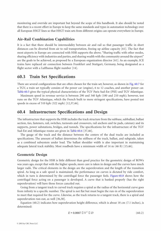
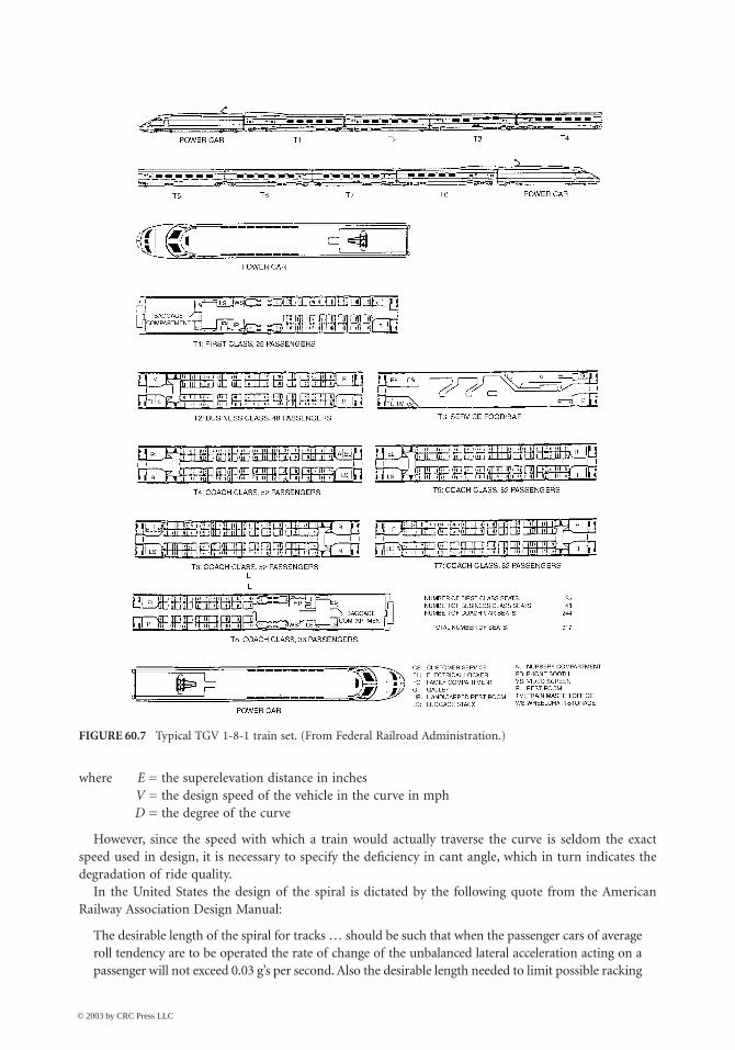
There are several configurations that are often chosen for the train set; however, as shown in Fig. 60.7 fora TGV, a train set typically consists of the power car (engine), 6 to 12 coaches, and another power car.Table 60.5 gives the typical physical characteristics of the TGV Paris Sud-Est (PSE) and TGV Atlantique.
Maximum speed in revenue service is between 290 and 340 kph (180 and 210 mph); however, testruns on the TGV Atlantique, which the French built to more stringent specifications, have posted testspeeds in excess of 510 kph (322 mph) [12,37,46].
60.4 Infrastructure Specifications and Design
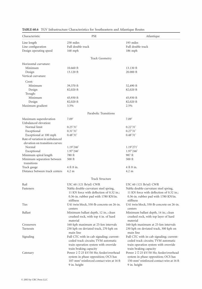
The infrastructure that supports the HSR includes the track structure from the subbase, subballast, ballastsection, ties, fasteners, rail, switches, turnouts and crossovers, rail anchors and tie pads, catenary and itssupports, power substations, bridges, and tunnels. The specifications for the infrastructure of the TGVSud-Est and Atlantique routes are given in Table 60.6 [37,46].
The gauge of the track and the distance between the centers of the dual tracks are included asspecifications. The amount of ballast determines the stiffness of the track, ballast, and subgrade, takenas a combined subsystem under load. The ballast shoulder width is also important in maintainingadequate lateral track stability. Most roadbeds have a minimum width of 14 m (46 ft) [15,46].
Geometric Design
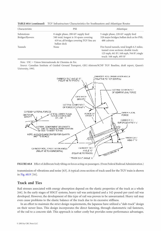
Geometric design for the HSR is little different than good practice for the geometric design of ROWswas years ago, except that with the higher speeds, more care is taken in design and the curves have muchlarger radii. The critical elements in the design are the superelevation and the length of the transitionspiral. As long as a safe speed is maintained, the performance on curves is dictated by ride comfort,which in turn is determined by the centrifugal force the passenger feels. Figure 60.8 shows how thecentrifugal force acting on a passenger is developed. A curve that is banked properly (has the rightsuperelevation) will have those forces canceled out.
Going from a tangent track to curved track requires a spiral as the radius of the horizontal curve goesfrom infinity to a specific number. The spiral is not flat but must begin the run-in of the superelevationto meet that required for the curve. Likewise, as the track returns to a tangent track, there is a spiral andsuperelevation run-out, as well [36,38].
Equation (60.2) indicates how superelevation height difference, which is about 18 cm (7.1 inches), isdetermined:
(60.2)E V D= ¥ ¥0 0007 2.
© 2003 by CRC Press LLC
High-Speed Ground Transportation: Planning and Design Issues 60-17
where E = the superelevation distance in inchesV = the design speed of the vehicle in the curve in mphD = the degree of the curve
However, since the speed with which a train would actually traverse the curve is seldom the exactspeed used in design, it is necessary to specify the deficiency in cant angle, which in turn indicates thedegradation of ride quality.
In the United States the design of the spiral is dictated by the following quote from the AmericanRailway Association Design Manual:
The desirable length of the spiral for tracks … should be such that when the passenger cars of averageroll tendency are to be operated the rate of change of the unbalanced lateral acceleration acting on apassenger will not exceed 0.03 g’s per second. Also the desirable length needed to limit possible racking
FIGURE 60.7 Typical TGV 1-8-1 train set. (From Federal Railroad Administration.)
© 2003 by CRC Press LLC

60-18 The Civil Engineering Handbook, Second Edition
and torsional forces produced should be such that the longitudinal slope of the outer rail with respectto the inner rail will not exceed 1/744 (based on an 85 foot car). [62]
The formulae given to achieve these results are expressed in Eqs. (60.3) and (60.4) [62]:
(60.3)
(60.4)
where L = the desirable minimum length of the spiral in feetV = the maximum train speed in mphEa = the actual elevation in inchesEu = the unbalanced elevation in inches
HSR track has to be able to provide accurate vehicle guidance at very high speeds and under variousweather conditions, to resist static forces, to withstand extensive dynamic loading, and to minimize the
TABLE 60.5 TGV Rolling Stock Characteristics for Southeastern and Atlantique Routes
Characteristic Atlantique PSE
Configuration 1-8-1 1-10-1Seating capacity 260 coach, 108 first 369 coach, 116 firstFleet size 95 passenger, 2 mail 105Dimensions:
Length 200 m 237.6 mWidth 2.8 m 2.8 mHeight 4.1 m 4.1 m
Total weight 416 tonnes 490 tonnesOperating speed 270 kph 300 kphTotal axles 26 30Maximum axle load 16.25 tonnes 17.00 tonnesTotal powered axles 12 8Unsprung mass 2.2 tonnes 2.2 tonnesTransmission type Sliding cardan shaft Sliding cardan shaftTraction:
Location Body mounted Body mountedType DC THO 676 AC synch, 3-phaseMotor power 525 kW 1100 kWTotal power 6300 kW 8800 kW
Full-power speed range 109–175 mph 80–186 mphStart-up tractive effort 212 KN 212 KNAdhesion:
At start 0.12 0.16At full speed 0.05 0.08
Brake system Rheostatic; disc brakes on unpowered axles; tread brakes on all wheels
Rheostatic and tread breaks on powered axles; 4 discs on unpowered axles
Stop distance from maximum speed 3.6 km 3.6 kmSuspension:
Primary Coil spring Coil springSecondary Coil spring SR10 airbag
Articulation Annular ring Annular ringCurrent collection MADE pantograph GPU pantographTruck Y230 motorized; Y231 trailer Y230A powered; Y237 A and B trailersWheel size 36 in. (920 mm) 36 in. (920 mm)Pressure sealed No No
Source: Canadian Institute of Guided Ground Transport, GEC-Alsthom/SCNF TGV Baseline, draft report, Queen’s Uni-versity, 1992.
L E Vu= ¥ ¥1 63.
L Ea= ¥62
© 2003 by CRC Press LLC
High-Speed Ground Transportation: Planning and Design Issues 60-19
TABLE 60.6 TGV Infrastructure Characteristics for Southeastern and Atlantique Routes
Characteristic PSE Atlantique
Line length 258 miles 193 milesLine configuration Full double track Full double trackDesign operating speed 168 mph 186 mph
Track Geometry
Horizontal curvature:Minimum 10.660 ft 13.130 ftDesign 13.120 ft 20.000 ft
Vertical curvature:
Crest:Minimum 39,370 ft 52,490 ftDesign 82,020 ft 82,020 ft
Trough:Minimum 45,930 ft 45,930 ftDesign 82,020 ft 82,020 ft
Maximum gradient 3.5% 2.5%
Parabolic Transitions
Maximum superelevation 7.09˚ 7.09˚Unbalanced elevation:
Normal limit 0.25˚31' 0.22˚31'Exceptional 0.31˚31' 0.27˚31'Exceptional at 100 mph 0.48˚31' 0.48˚31'
Rate of variation in unbalanced elevation on transition curves:
Normal 1.19˚246' 1.19˚271'Exceptional 1.97˚246' 1.97˚246'
Minimum spiral length 780 ft 987 ftMinimum separation between
transitions500 ft 500 ft
Track gauge 4 ft 8 in. 4 ft 8 in.Distance between track centers 4.2 m 4.2 m
Track Structure
Rail UIC 60 (121 lb/yd) CWR UIC 60 (121 lb/yd) CWRFasteners Nabla double-curvature steel spring,
11 KN force with deflection of 0.32 in.; 0.36-in. rubber pad with 1780 KN/in. stiffness
Nabla double-curvature steel spring, 11 KN force with deflection of 0.32 in.; 0.36-in. rubber pad with 1780 KN/in. stiffness
Ties U41 twin block, 550-lb concrete on 26-in. centers
U41 twin block, 550-lb concrete on 26-in. centers
Ballast Minimum ballast depth, 12 in.; clean crushed rock, with top 4 in. of hard material
Minimum ballast depth, 14 in.; clean crushed rock, with top layer of hard material
Crossovers 160-kph maximum at 25-km intervals 160-kph maximum at 25-km intervalsTurnouts 230 kph on deviated track, 270 kph on
main line230 kph on deviated track, 300 kph on
main lineSignaling Full CTC with in-cab signaling; current-
coded track circuits; TVM automatic train operation system with override train braking capacity
Full CTC with in-cab signaling; current- coded track circuits; TVM automatic train operation system with override train braking capacity
Catenary Power 2 ¥ 25 kV/50 Hz; feeder/overhead system in phase opposition; OCS has 107-mm2 reinforced contact wire at 16 ft 9 in. height
Power 2 ¥ 25 kV/50 Hz; feeder/overhead system in phase opposition; OCS has 150-mm2 reinforced contact wire at 16 ft 9 in. height
© 2003 by CRC Press LLC
60-20 The Civil Engineering Handbook, Second Edition
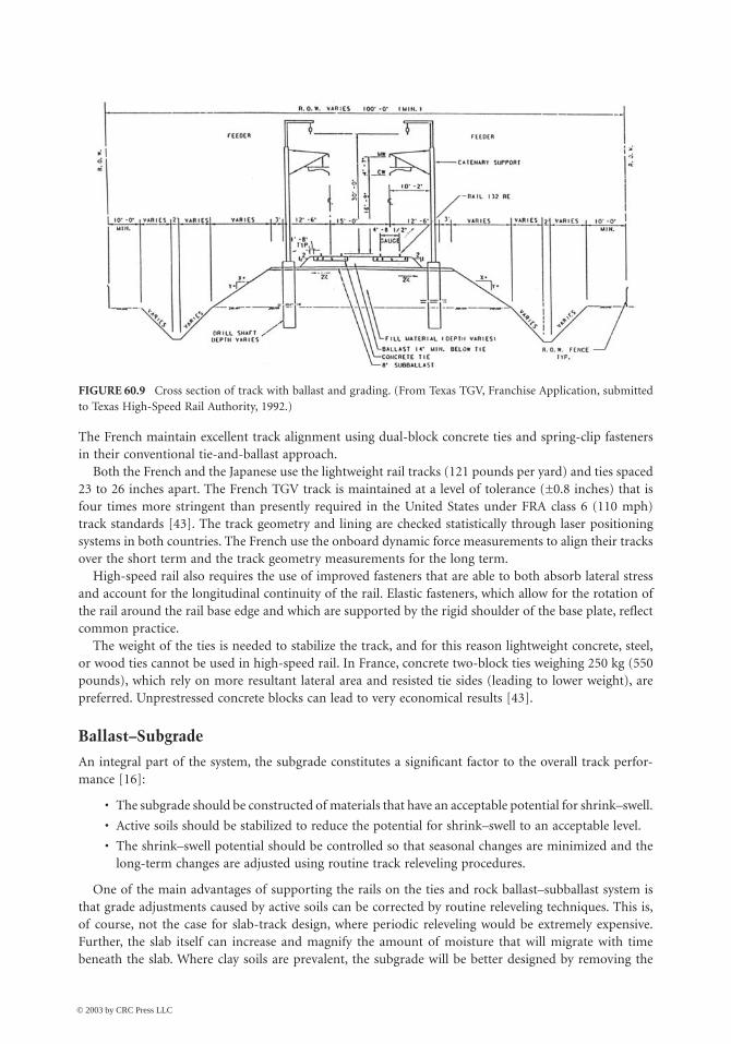
transmission of vibrations and noise [63]. A typical cross section of track used for the TGV train is shownin Fig. 60.9 [16].
Track and Ties
Rail stresses associated with energy absorption depend on the elastic properties of the track as a whole[64]. In the early stages of HSGT systems, heavy rail was anticipated and a 142-pound-per-yard rail wasdeveloped. However, the development of this type of rail was proven to be unwarranted. Heavy rail mayeven cause problems to the elastic balance of the track due to its excessive stiffness.
In an effort to maintain the strict design requirements, the Japanese have utilized a “slab-track” designon their newer lines. This design incorporates the direct fastening, through elastometric rail fasteners,of the rail to a concrete slab. This approach is rather costly but provides some performance advantages.
TABLE 60.6 (continued) TGV Infrastructure Characteristics for Southeastern and Atlantique Routes
Characteristic PSE Atlantique
Substations 8 single phase, 200-kV supply feed 5 single phase, 220-kV supply feedBridges/flyovers 540 total, longest is 10 spans covering
419 m; all bridges covering TGV line are ballast deck
328 major bridges; ballast deck as for PSE; 488 culverts
Tunnels None Five bored tunnels, total length 6.3 miles; tunnel cross sections: double truck: 125 mph, 441 ft2; 168 mph, 764 ft2; single truck: 168 mph, 495 ft2
Note: UIC = Union Internationale de Chemins de Fer.Source: Canadian Institute of Guided Ground Transport, GEC-Alstrom/SCNF TGV Baseline, draft report, Queen’s
University, 1992.
FIGURE 60.8 Effect of deliberate body tilting on forces acting on passengers. (From Federal Railroad Administration.)
© 2003 by CRC Press LLC
High-Speed Ground Transportation: Planning and Design Issues 60-21
The French maintain excellent track alignment using dual-block concrete ties and spring-clip fastenersin their conventional tie-and-ballast approach.
Both the French and the Japanese use the lightweight rail tracks (121 pounds per yard) and ties spaced23 to 26 inches apart. The French TGV track is maintained at a level of tolerance (±0.8 inches) that isfour times more stringent than presently required in the United States under FRA class 6 (110 mph)track standards [43]. The track geometry and lining are checked statistically through laser positioningsystems in both countries. The French use the onboard dynamic force measurements to align their tracksover the short term and the track geometry measurements for the long term.
High-speed rail also requires the use of improved fasteners that are able to both absorb lateral stressand account for the longitudinal continuity of the rail. Elastic fasteners, which allow for the rotation ofthe rail around the rail base edge and which are supported by the rigid shoulder of the base plate, reflectcommon practice.
The weight of the ties is needed to stabilize the track, and for this reason lightweight concrete, steel,or wood ties cannot be used in high-speed rail. In France, concrete two-block ties weighing 250 kg (550pounds), which rely on more resultant lateral area and resisted tie sides (leading to lower weight), arepreferred. Unprestressed concrete blocks can lead to very economical results [43].
Ballast–Subgrade
An integral part of the system, the subgrade constitutes a significant factor to the overall track perfor-mance [16]:
• The subgrade should be constructed of materials that have an acceptable potential for shrink–swell.
• Active soils should be stabilized to reduce the potential for shrink–swell to an acceptable level.
• The shrink–swell potential should be controlled so that seasonal changes are minimized and thelong-term changes are adjusted using routine track releveling procedures.
One of the main advantages of supporting the rails on the ties and rock ballast–subballast system isthat grade adjustments caused by active soils can be corrected by routine releveling techniques. This is,of course, not the case for slab-track design, where periodic releveling would be extremely expensive.Further, the slab itself can increase and magnify the amount of moisture that will migrate with timebeneath the slab. Where clay soils are prevalent, the subgrade will be better designed by removing the
FIGURE 60.9 Cross section of track with ballast and grading. (From Texas TGV, Franchise Application, submittedto Texas High-Speed Rail Authority, 1992.)
© 2003 by CRC Press LLC
60-22 The Civil Engineering Handbook, Second Edition
clay and replacing it with a compacted granular soil or by using in-place stabilization with materials suchas liquid lime or fly ash slurry.
For the Atlantique the minimum ballast section is 35 cm of crushed rock laid in two stages beneaththe ties. The ballast grading provides material 1# to 2# size. The bottom layer of normal stone iscompacted and the track placed on it. The top layer of harder material is then stabilized by vibrationafter the track has been lifted by tampers. A sub-ballast layer separates the ballast and the subgradematerials. Prior to the record setting run in May 1990, ballast cleaning was undertaken to ensure thatthere were no fine materials that could be blown up by the slipstream. [46]
Catenary
The catenary system is basically state of the art, with special attention given to providing [16]
• Ample tension on the contact wire to reduce uplift, thereby improving the collection capacity ofthe pantograph
• A more rigid suspension system to prevent swaying in lateral winds
• Use of flattened contact wire to reduce wear on both the contact wire and the current collector
• The spacing of support poles from 30 to 70 m, depending on the mechanical requirements of thesystem at any given location
60.5 Track–Train Interactions
Using Existing ROW
With the difficulty in procuring large portions of new rights-of-way, in raising the new capital fromprivate sources, and in building new infrastructure, it becomes imperative that engineers find ways ofbetter using the existing track. The principal problems are:
• The tightness of curves built for slower trains will cause a loss of average speed and energy becauseof constantly accelerating and decelerating.
• The ride quality will suffer because the superelevation is designed for much slower trains.
• The track, ballast, and subgrade may not have the width to provide the lateral stability needed.
• Grade separation does not exist and will require special provision for safety.
• The change to electrification of the line will have to be accommodated.
• Access to the ROW will have to be restricted.
In any event, the roadbed will almost always require some rehabilitation and upgrading. Signaling willhave to be upgraded in order to account for the higher speed. The potential of mixed freight and HSRoperations may call for more siding and more frequent inspection and realignment. One solution is todepend more on the train set. The result is trains with active tilting capability.
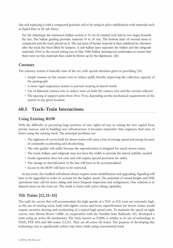
Tilt Trains [12,32–35]
The radii for curves that will accommodate the high speeds of a TGV or ICE train are extremely high,so the use of existing track, built with tighter curves and lower superelevation for slower trains, wouldrequire excessive slowing and accelerating of a typical high-speed train. To maintain the speed on tightcurves, Asea Brown Boveri (ABB), in cooperation with the Swedish State Railroads (SJ), developed atrain using an active tilt mechanism. The train, known as X2000, is similar in its use of technology toFIATs, ETR 450, and 460 trains [12,35]. They are all active tilt trains. The purpose of developing thistechnology was to significantly reduce trip times while using conventional track.
© 2003 by CRC Press LLC

High-Speed Ground Transportation: Planning and Design Issues 60-23
The X2000 features a self-steering radial truck that consists of a rigid frame in which two wheel setsare mounted in parallel. As the stiff truck travels through curves, the axles remain parallel to each other,exerting forces on the rails [32]. The higher the speed for a given curve radius, the greater the tendencyof the wheels in the normal truck assembly to try to overturn the rail (rollover) or to climb over the rail(climbing). The solution given by ABB was the self-steering radial truck. A soft chevron primary sus-pension system allows each truck to assume its natural radial position in each curve [33]. The result isa redistribution of forces exerted by the wheel sets. For example, the X2000 exerts no more force roundinga curve at 125 mph than does a regular train at 80 mph. The result of this capability is that it allows forsignificantly higher average speed.
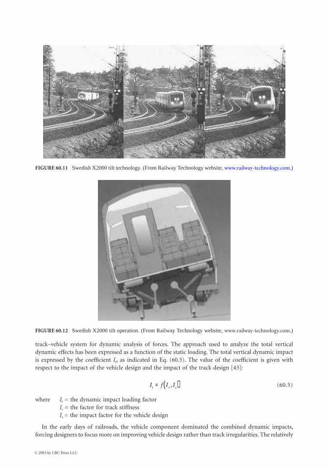
The active car body tilting system, shown in Fig. 60.10, was developed mainly for passenger comfort.Along with the increase of train speeds in the curves come associated lateral forces experienced by thepassengers. By anticipating each curve and causing the car bodies to tilt inward at the appropriate angles,centrifugal forces are compensated and passenger comfort is maintained. The X2000 is designed forspeeds of 201 kph (125 mph) in Sweden, and it has been tested at 250 kph (156 mph) in Germany [32].The X2000 operated in revenue service in the Northeast corridor for several months. Tilt technology isbeing used in several HSR trains around the world. Figures 60.11 and 60.12 show the Swedish X2000’stilt technology and operation.
Train–Track Dynamics
The design of track components, special track work, ballast, subballast, and subgrade and the acceptanceof soils are controlled by the dynamic loading associated with track irregularities. Figure 60.15 shows the
FIGURE 60.10 Location of car body roll center and center of gravity for passive and active body tilting. (FromFederal Railroad Administration.)
© 2003 by CRC Press LLC
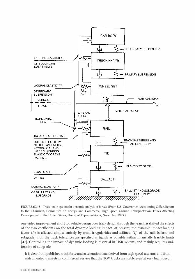
60-24 The Civil Engineering Handbook, Second Edition
track–vehicle system for dynamic analysis of forces. The approach used to analyze the total verticaldynamic effects has been expressed as a function of the static loading. The total vertical dynamic impactis expressed by the coefficient It, as indicated in Eq. (60.5). The value of the coefficient is given withrespect to the impact of the vehicle design and the impact of the track design [43]:
(60.5)
where It = the dynamic impact loading factorIs = the factor for track stiffnessIv = the impact factor for the vehicle design
In the early days of railroads, the vehicle component dominated the combined dynamic impacts,forcing designers to focus more on improving vehicle design rather than track irregularities. The relatively
FIGURE 60.11 Swedish X2000 tilt technology. (From Railway Technology website, www.railway-technology.com.)
FIGURE 60.12 Swedish X2000 tilt operation. (From Railway Technology website, www.railway-technology.com.)
I f I It v s= ( ),
© 2003 by CRC Press LLC
High-Speed Ground Transportation: Planning and Design Issues 60-25
one-sided improvement effort for vehicle design over track design through the years has shifted the effectsof the two coefficients on the total dynamic loading impact. At present, the dynamic impact loadingfactor (It) is affected almost entirely by track irregularities and stiffness (Is) of the rail, ballast, andsubgrade; thus, the track tolerances are specified as tightly as possible within financially feasible limits[47]. Controlling the impact of dynamic loading is essential in HSR systems and mainly requires uni-formity of subgrade.
It is clear from published track force and acceleration data derived from high speed test runs and frominstrumented trainsets in commercial service that the TGV trucks are stable even at very high speed,
FIGURE 60.13 Track–train system for dynamic analysis of forces. (From U.S. Government Accounting Office, Reportto the Chairman, Committee on Energy and Commerce, High-Speed Ground Transportation: Issues AffectingDevelopment in the United States, House of Representatives, November 1993.)
© 2003 by CRC Press LLC

60-26 The Civil Engineering Handbook, Second Edition
and that the dynamic force and acceleration levels are well within limits established by SNCF. … Forthe December 1989 test run at 482 kph, the measured maximum vertical accelerations were 3 g to 4 gat the tie and 1 g to 1.5 g in the ballast, about the same as those measured for a conventional locomotive-hauled passenger train at 200 kph and well within established limits. Measured lateral force reacheda maximum of 48 kN. In fact, the lateral resistance of the TGV track, which uses concrete ties anddynamic stabilization, is more than double the Prud’homme limit [126 kN vs. 57 kN]. [12,14].
FIGURE 60.14 Picture of ACELA Express. (From Railway Technology website, www.railway-technology.com.)
FIGURE 60.15 The original TGV. (From Dechamps, F.)
© 2003 by CRC Press LLC
High-Speed Ground Transportation: Planning and Design Issues 60-27
60.6 HSR Examples Worldwide
Introduction
Unlike in the United States, where HRS implementation is still in the planning phases (except for theACELA HSR, which started operating in 2000), in other places of the world (Europe and Asia), HSRtrains are either operating or in the phase of near future implementation. Such systems will be discussedin the following paragraphs.
United States: The ACELA Express [12,20]
ACELA is the first HSR train to be used in the United States. It was because of Amtrak’s efforts since1996 to improve its operations in the Northeastern corridor from Washington, D.C., to Boston, wherethe company holds about 45% of the passenger market, that it was decided to put an HSR train intoservice. It was also decided that existing tracks would be used and that with some upgrades tilt technologywould be implemented. Also, the whole corridor would be electrified (completed in late 1999). Theservice started operating in December 2000. The ACELA managed to cut the time from Boston to NewYork from 4 h 30 min to a little more than 3 h.
The ACELA train set is based on the TGV, but it is largely constructed in the United States. It wasunveiled in March 1999 after a number of controversies that delayed its appearance. It should be notedthat TGV technology was finally selected after examining the German ICE technology and the SwedishX2000 tilt technology. (Both train sets were demonstrated in the United States in 1993). The building ofthe ACELA train set started in 1998, along with the NEC modifications. As for the ACELA train settechnology, it was based on used and proven technologies. The ACELA can achieve speeds of 150 mphand has a length of 202 m and a weight of 566 tonnes. Its configuration is that of 1 power car, 6 cars,and another power car, giving it the ability to carry 304 passengers. The six cars consist of one first-classcar, four business-class cars, and a dining car.
The ACELA uses the third-generation TGV traction technology and tilt technology in its suspensions(up to 6.5 degrees), and it complies with the FRA’s standards on possible crushes, which are the toughestaround the world. For that reason, the ACELA is significantly heavier than other HSR trains worldwide(45% heavier than the TGV). The signaling and safety systems, as well as the monitoring system, are alsotechnologically advanced, to ensure maximum safety on the existing corridor.
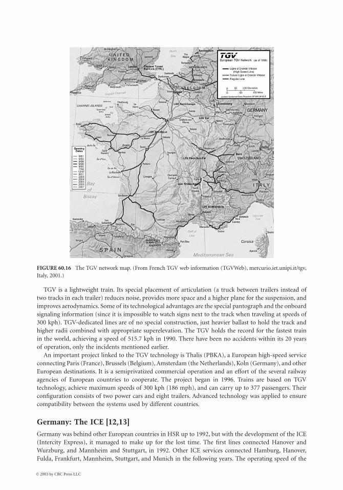
France: The TGV [12,14]
The TGV (Train Grande Vitesse) is the French HSR train. Since there are significant differences among the350 train sets based on the TGV, a more appropriate term would be “a system which comprises train, trackand signaling technologies that when combined, allow the train to achieve high speeds (300 kph)” [14].
TGV is owned by Societe Nationale de Chemins de Fer Francais (SNCF), the French national railways,and it is an integral part of French rail travel.
When developing the TGV, SNCF wanted a train to be able to use existing tracks on high speeds,especially in main cities, where new tracks would be difficult to construct and expensive. The firstprototype of the TGV train set began testing in the early 1970s. The first line to be operated by the TGVwas completed and started operation in 1981, connecting Paris with Lyon. Its success gutted theParis–Lyon airline connection and freed the expressway connecting the two cities. The TGV became oneof the few parts of SNCF that gained profit, and within ten years of its initiation, it had completely paidfor itself. Since 1981, new lines have been built in France and neighboring countries. TGV Atlantiquewas initiated in 1989, connecting Paris with western points of France. Today there are three major lines,with Paris at their center. The most recent line connects Paris to Lille, Belgium, the Netherlands, Germany,and Britain (through the Channel tunnel). TGV technology is also applied in other countries.
© 2003 by CRC Press LLC
60-28 The Civil Engineering Handbook, Second Edition
TGV is a lightweight train. Its special placement of articulation (a truck between trailers instead oftwo tracks in each trailer) reduces noise, provides more space and a higher plane for the suspension, andimproves aerodynamics. Some of its technological advantages are the special pantograph and the onboardsignaling information (since it is impossible to watch signs next to the track when traveling at speeds of300 kph). TGV-dedicated lines are of no special construction, just heavier ballast to hold the track andhigher radii combined with appropriate superelevation. The TGV holds the record for the fastest trainin the world, achieving a speed of 515.7 kph in 1990. There have been no accidents within its 20 yearsof operation, only the incidents mentioned earlier.
An important project linked to the TGV technology is Thalis (PBKA), a European high-speed serviceconnecting Paris (France), Brussels (Belgium), Amsterdam (the Netherlands), Koln (Germany), and otherEuropean destinations. It is a semiprivatized commercial operation and an effort of the several railwayagencies of European countries to cooperate. The project began in 1996. Trains are based on TGVtechnology, achieve maximum speeds of 300 kph (186 mph), and can carry up to 377 passengers. Theirconfiguration consists of two power cars and eight trailers. Advanced technology was applied to ensurecompatibility between the systems used by different countries.
Germany: The ICE [12,13]
Germany was behind other European countries in HSR up to 1992, but with the development of the ICE(Intercity Express), it managed to make up for the lost time. The first lines connected Hanover andWurzburg, and Mannheim and Stuttgart, in 1992. Other ICE services connected Hamburg, Hanover,Fulda, Frankfurt, Mannheim, Stuttgart, and Munich in the following years. The operating speed of the
FIGURE 60.16 The TGV network map. (From French TGV web information (TGVWeb), mercurio.iet.unipi.it/tgv,Italy, 2001.)
© 2003 by CRC Press LLC
High-Speed Ground Transportation: Planning and Design Issues 60-29
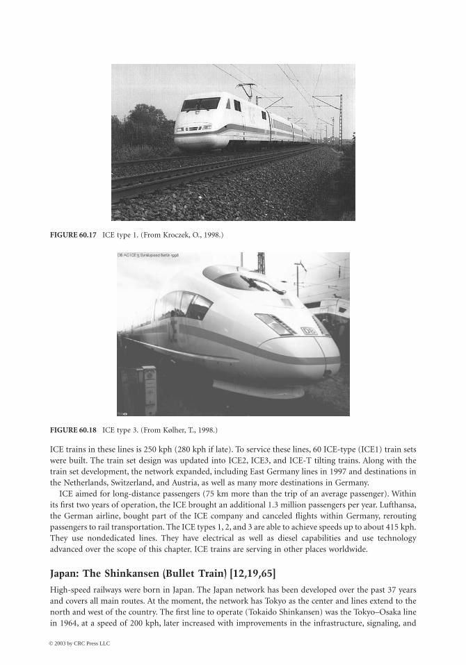
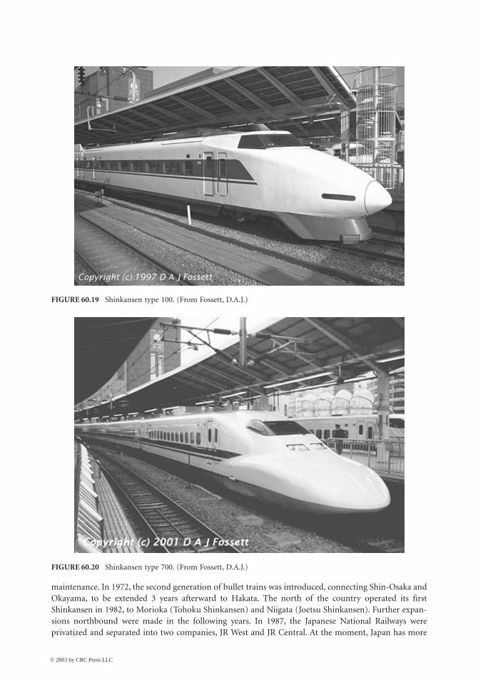
ICE trains in these lines is 250 kph (280 kph if late). To service these lines, 60 ICE-type (ICE1) train setswere built. The train set design was updated into ICE2, ICE3, and ICE-T tilting trains. Along with thetrain set development, the network expanded, including East Germany lines in 1997 and destinations inthe Netherlands, Switzerland, and Austria, as well as many more destinations in Germany.
ICE aimed for long-distance passengers (75 km more than the trip of an average passenger). Withinits first two years of operation, the ICE brought an additional 1.3 million passengers per year. Lufthansa,the German airline, bought part of the ICE company and canceled flights within Germany, reroutingpassengers to rail transportation. The ICE types 1, 2, and 3 are able to achieve speeds up to about 415 kph.They use nondedicated lines. They have electrical as well as diesel capabilities and use technologyadvanced over the scope of this chapter. ICE trains are serving in other places worldwide.
Japan: The Shinkansen (Bullet Train) [12,19,65]
High-speed railways were born in Japan. The Japan network has been developed over the past 37 yearsand covers all main routes. At the moment, the network has Tokyo as the center and lines extend to thenorth and west of the country. The first line to operate (Tokaido Shinkansen) was the Tokyo–Osaka linein 1964, at a speed of 200 kph, later increased with improvements in the infrastructure, signaling, and
FIGURE 60.17 ICE type 1. (From Kroczek, O., 1998.)
FIGURE 60.18 ICE type 3. (From Kølher, T., 1998.)
© 2003 by CRC Press LLC
60-30 The Civil Engineering Handbook, Second Edition
maintenance. In 1972, the second generation of bullet trains was introduced, connecting Shin-Osaka andOkayama, to be extended 3 years afterward to Hakata. The north of the country operated its firstShinkansen in 1982, to Morioka (Tohoku Shinkansen) and Niigata (Joetsu Shinkansen). Further expan-sions northbound were made in the following years. In 1987, the Japanese National Railways wereprivatized and separated into two companies, JR West and JR Central. At the moment, Japan has more
FIGURE 60.19 Shinkansen type 100. (From Fossett, D.A.J.)
FIGURE 60.20 Shinkansen type 700. (From Fossett, D.A.J.)
© 2003 by CRC Press LLC
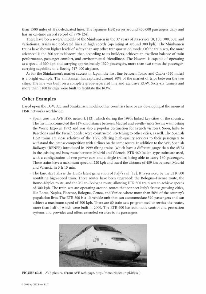
High-Speed Ground Transportation: Planning and Design Issues 60-31
than 1500 miles of HSR-dedicated lines. The Japanese HSR serves around 400,000 passengers daily andhas an on-time arrival record of 99% [24].
There have been several models of the Shinkansen in the 37 years of its service (0, 100, 300, 500, andvariations). Trains use dedicated lines in high speeds (operating at around 300 kph). The Shinkansentrains have shown higher levels of safety than any other transportation mode. Of the train sets, the moreadvanced is the 500 series Nozomi that, according to its builders, achieves an excellent balance of trainperformance, passenger comfort, and environmental friendliness. The Nozomi is capable of operatingat a speed of 300 kph and carrying approximately 1320 passengers, more than two times the passenger-carrying capability of a Boeing 747-400 airplane.
As for the Shinkansen’s market success in Japan, the first line between Tokyo and Osaka (320 miles)is a bright example. The Shinkansen has captured around 80% of the market of trips between the twocities. The line was built on a complete grade-separated line and exclusive ROW. Sixty-six tunnels andmore than 3100 bridges were built to facilitate the ROW.
Other Examples
Based upon the TGV, ICE, and Shinkansen models, other countries have or are developing at the momentHSR networks worldwide:
• Spain uses the AVE HSR network [12], which during the 1990s linked key cities of the country.The first link connected the 417-km distance between Madrid and Seville (since Seville was hostingthe World Expo in 1992 and was also a popular destination for French visitors). Soon, links toBarcelona and the French border were constructed, stretching to other cities, as well. The SpanishHSR trains are close relatives of the TGV, offering high-quality services to their passengers towithstand the intense competition with airlines on the same routes. In addition to the AVE, SpanishRailways (RENFE) introduced in 1999 tilting trains (which have a different gauge than the AVE)in the existing and busy route between Madrid and Valencia. ETR 460 Italian-type trains are used,with a configuration of two power cars and a single trailer, being able to carry 160 passengers.These trains have a maximum speed of 220 kph and travel the distance of 489 km between Madridand Valencia in 3 h 15 min.
• The Eurostar Italia is the HSR’s latest generation of Italy’s rail [12]. It is serviced by the ETR 500nontilting high-speed train. Three routes have been upgraded: the Bologna–Firenze route, theRome–Naples route, and the Milan–Bologna route, allowing ETR 500 train sets to achieve speedsof 300 kph. The train sets are operating around routes that connect Italy’s fastest-growing cities,like Rome, Naples, Florence, Bologna, Genoa, and Venice, where more than 50% of the country’spopulation lives. The ETR 500 is a 13-vehicle unit that can accommodate 590 passengers and canachieve a maximum speed of 300 kph. There are 60 train sets programmed to service the routes,more than half of which were built in 2000. The ETR 500 has automatic control and protectionsystems and provides and offers extended services to its passengers.
FIGURE 60.21 AVE picture. (From AVE web page, http://mercurio.iet.unipi.it/ave.)
© 2003 by CRC Press LLC
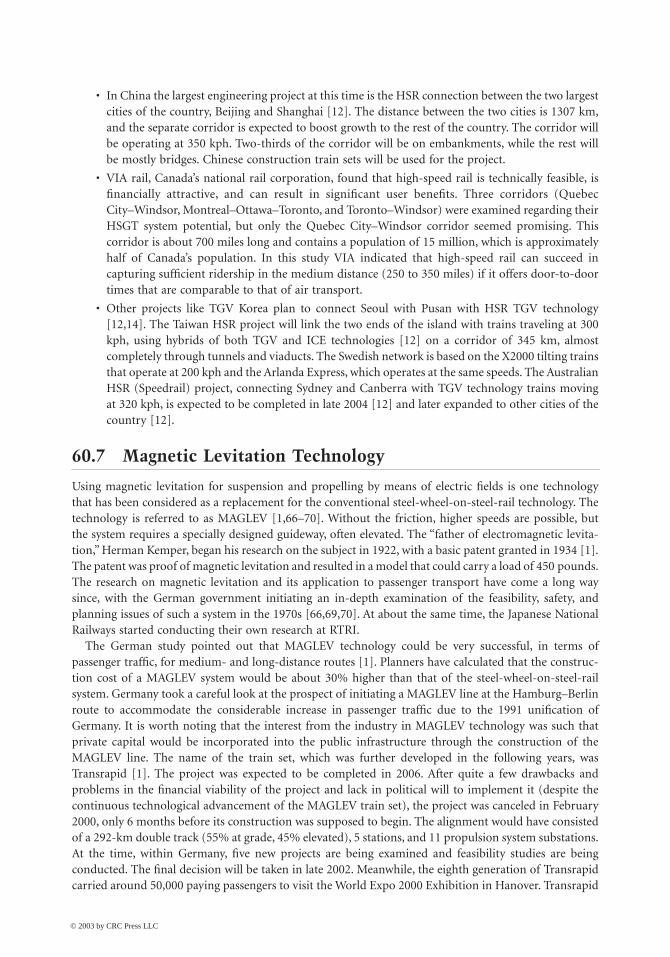
60-32 The Civil Engineering Handbook, Second Edition
• In China the largest engineering project at this time is the HSR connection between the two largestcities of the country, Beijing and Shanghai [12]. The distance between the two cities is 1307 km,and the separate corridor is expected to boost growth to the rest of the country. The corridor willbe operating at 350 kph. Two-thirds of the corridor will be on embankments, while the rest willbe mostly bridges. Chinese construction train sets will be used for the project.
• VIA rail, Canada’s national rail corporation, found that high-speed rail is technically feasible, isfinancially attractive, and can result in significant user benefits. Three corridors (QuebecCity–Windsor, Montreal–Ottawa–Toronto, and Toronto–Windsor) were examined regarding theirHSGT system potential, but only the Quebec City–Windsor corridor seemed promising. Thiscorridor is about 700 miles long and contains a population of 15 million, which is approximatelyhalf of Canada’s population. In this study VIA indicated that high-speed rail can succeed incapturing sufficient ridership in the medium distance (250 to 350 miles) if it offers door-to-doortimes that are comparable to that of air transport.
• Other projects like TGV Korea plan to connect Seoul with Pusan with HSR TGV technology[12,14]. The Taiwan HSR project will link the two ends of the island with trains traveling at 300kph, using hybrids of both TGV and ICE technologies [12] on a corridor of 345 km, almostcompletely through tunnels and viaducts. The Swedish network is based on the X2000 tilting trainsthat operate at 200 kph and the Arlanda Express, which operates at the same speeds. The AustralianHSR (Speedrail) project, connecting Sydney and Canberra with TGV technology trains movingat 320 kph, is expected to be completed in late 2004 [12] and later expanded to other cities of thecountry [12].
60.7 Magnetic Levitation Technology
Using magnetic levitation for suspension and propelling by means of electric fields is one technologythat has been considered as a replacement for the conventional steel-wheel-on-steel-rail technology. Thetechnology is referred to as MAGLEV [1,66–70]. Without the friction, higher speeds are possible, butthe system requires a specially designed guideway, often elevated. The “father of electromagnetic levita-tion,” Herman Kemper, began his research on the subject in 1922, with a basic patent granted in 1934 [1].The patent was proof of magnetic levitation and resulted in a model that could carry a load of 450 pounds.The research on magnetic levitation and its application to passenger transport have come a long waysince, with the German government initiating an in-depth examination of the feasibility, safety, andplanning issues of such a system in the 1970s [66,69,70]. At about the same time, the Japanese NationalRailways started conducting their own research at RTRI.
The German study pointed out that MAGLEV technology could be very successful, in terms ofpassenger traffic, for medium- and long-distance routes [1]. Planners have calculated that the construc-tion cost of a MAGLEV system would be about 30% higher than that of the steel-wheel-on-steel-railsystem. Germany took a careful look at the prospect of initiating a MAGLEV line at the Hamburg–Berlinroute to accommodate the considerable increase in passenger traffic due to the 1991 unification ofGermany. It is worth noting that the interest from the industry in MAGLEV technology was such thatprivate capital would be incorporated into the public infrastructure through the construction of theMAGLEV line. The name of the train set, which was further developed in the following years, wasTransrapid [1]. The project was expected to be completed in 2006. After quite a few drawbacks andproblems in the financial viability of the project and lack in political will to implement it (despite thecontinuous technological advancement of the MAGLEV train set), the project was canceled in February2000, only 6 months before its construction was supposed to begin. The alignment would have consistedof a 292-km double track (55% at grade, 45% elevated), 5 stations, and 11 propulsion system substations.At the time, within Germany, five new projects are being examined and feasibility studies are beingconducted. The final decision will be taken in late 2002. Meanwhile, the eighth generation of Transrapidcarried around 50,000 paying passengers to visit the World Expo 2000 Exhibition in Hanover. Transrapid
© 2003 by CRC Press LLC

High-Speed Ground Transportation: Planning and Design Issues 60-33
feasibility and implementation studies are also being conducted around the world. The first project tobe completed in a few years is the connection of the Shanghai Airport with Shanghai, China. The Chineseare also considering construction of MAGLEV lines from Shanghai to Beijing (1307 km) instead ofapplying an HSR corridor of the conventional type. In the United States, TEA 21 will be funding feasibilityand implementation studies of the Transrapid in the California–Nevada (Las Vegas–Barstow–OntarioCounty, California North–South), Florida (Orlando–Port Canaveral), Pennsylvania, and Balti-more–Washington, D.C., corridors.
As for Japanese MAGLEV trains, called MLU [74], the Japanese have been testing them and developingtheir technology from time to time. The only track existing in Japan is a 7-km test track. The latest MLUvehicle (five cars) managed to achieve a speed of 552 kph (manned vehicle) in the test track in April1999 [67].
FIGURE 60.22 Transrapid figure and technology. (From Transrapid website, www.transrapid-international.de/en,Germany, 2001.)
FIGURE 60.23 MLU design. (From RTRI.)
© 2003 by CRC Press LLC
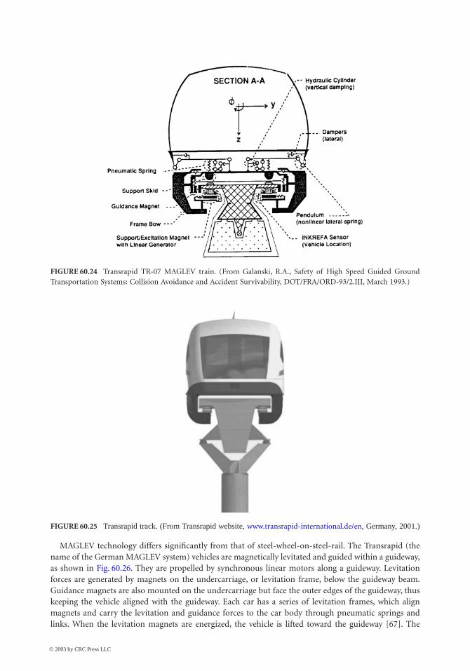
60-34 The Civil Engineering Handbook, Second Edition
MAGLEV technology differs significantly from that of steel-wheel-on-steel-rail. The Transrapid (thename of the German MAGLEV system) vehicles are magnetically levitated and guided within a guideway,as shown in Fig. 60.26. They are propelled by synchronous linear motors along a guideway. Levitationforces are generated by magnets on the undercarriage, or levitation frame, below the guideway beam.Guidance magnets are also mounted on the undercarriage but face the outer edges of the guideway, thuskeeping the vehicle aligned with the guideway. Each car has a series of levitation frames, which alignmagnets and carry the levitation and guidance forces to the car body through pneumatic springs andlinks. When the levitation magnets are energized, the vehicle is lifted toward the guideway [67]. The
FIGURE 60.24 Transrapid TR-07 MAGLEV train. (From Galanski, R.A., Safety of High Speed Guided GroundTransportation Systems: Collision Avoidance and Accident Survivability, DOT/FRA/ORD-93/2.III, March 1993.)
FIGURE 60.25 Transrapid track. (From Transrapid website, www.transrapid-international.de/en, Germany, 2001.)
© 2003 by CRC Press LLC
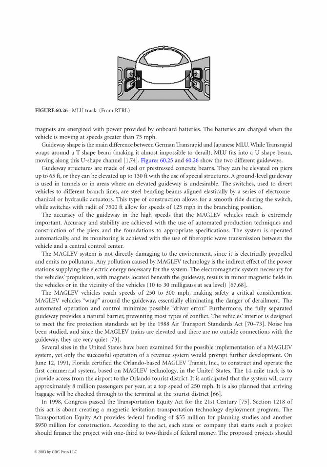
High-Speed Ground Transportation: Planning and Design Issues 60-35
magnets are energized with power provided by onboard batteries. The batteries are charged when thevehicle is moving at speeds greater than 75 mph.
Guideway shape is the main difference between German Transrapid and Japanese MLU. While Transrapidwraps around a T-shape beam (making it almost impossible to derail), MLU fits into a U-shape beam,moving along this U-shape channel [1,74]. Figures 60.25 and 60.26 show the two different guideways.
Guideway structures are made of steel or prestressed concrete beams. They can be elevated on piersup to 65 ft, or they can be elevated up to 130 ft with the use of special structures. A ground-level guidewayis used in tunnels or in areas where an elevated guideway is undesirable. The switches, used to divertvehicles to different branch lines, are steel bending beams aligned elastically by a series of electrome-chanical or hydraulic actuators. This type of construction allows for a smooth ride during the switch,while switches with radii of 7500 ft allow for speeds of 125 mph in the branching position.
The accuracy of the guideway in the high speeds that the MAGLEV vehicles reach is extremelyimportant. Accuracy and stability are achieved with the use of automated production techniques andconstruction of the piers and the foundations to appropriate specifications. The system is operatedautomatically, and its monitoring is achieved with the use of fiberoptic wave transmission between thevehicle and a central control center.
The MAGLEV system is not directly damaging to the environment, since it is electrically propelledand emits no pollutants. Any pollution caused by MAGLEV technology is the indirect effect of the powerstations supplying the electric energy necessary for the system. The electromagnetic system necessary forthe vehicles’ propulsion, with magnets located beneath the guideway, results in minor magnetic fields inthe vehicles or in the vicinity of the vehicles (10 to 30 milligauss at sea level) [67,68].
The MAGLEV vehicles reach speeds of 250 to 300 mph, making safety a critical consideration.MAGLEV vehicles “wrap” around the guideway, essentially eliminating the danger of derailment. Theautomated operation and control minimize possible “driver error.” Furthermore, the fully separatedguideway provides a natural barrier, preventing most types of conflict. The vehicles’ interior is designedto meet the fire protection standards set by the 1988 Air Transport Standards Act [70–73]. Noise hasbeen studied, and since the MAGLEV trains are elevated and there are no outside connections with theguideway, they are very quiet [73].
Several sites in the United States have been examined for the possible implementation of a MAGLEVsystem, yet only the successful operation of a revenue system would prompt further development. OnJune 12, 1991, Florida certified the Orlando-based MAGLEV Transit, Inc., to construct and operate thefirst commercial system, based on MAGLEV technology, in the United States. The 14-mile track is toprovide access from the airport to the Orlando tourist district. It is anticipated that the system will carryapproximately 8 million passengers per year, at a top speed of 250 mph. It is also planned that arrivingbaggage will be checked through to the terminal at the tourist district [66].
In 1998, Congress passed the Transportation Equity Act for the 21st Century [75]. Section 1218 ofthis act is about creating a magnetic levitation transportation technology deployment program. TheTransportation Equity Act provides federal funding of $55 million for planning studies and another$950 million for construction. According to the act, each state or company that starts such a projectshould finance the project with one-third to two-thirds of federal money. The proposed projects should
FIGURE 60.26 MLU track. (From RTRI.)
© 2003 by CRC Press LLC
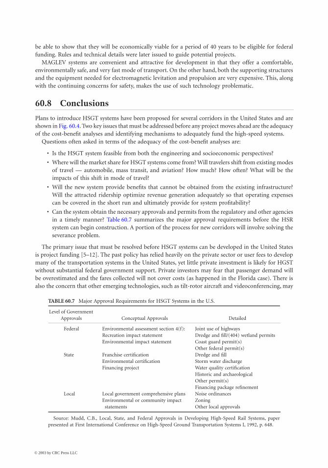
60-36 The Civil Engineering Handbook, Second Edition
be able to show that they will be economically viable for a period of 40 years to be eligible for federalfunding. Rules and technical details were later issued to guide potential projects.
MAGLEV systems are convenient and attractive for development in that they offer a comfortable,environmentally safe, and very fast mode of transport. On the other hand, both the supporting structuresand the equipment needed for electromagnetic levitation and propulsion are very expensive. This, alongwith the continuing concerns for safety, makes the use of such technology problematic.
60.8 Conclusions
Plans to introduce HSGT systems have been proposed for several corridors in the United States and areshown in Fig. 60.4. Two key issues that must be addressed before any project moves ahead are the adequacyof the cost-benefit analyses and identifying mechanisms to adequately fund the high-speed systems.
Questions often asked in terms of the adequacy of the cost-benefit analyses are:
• Is the HSGT system feasible from both the engineering and socioeconomic perspectives?
• Where will the market share for HSGT systems come from? Will travelers shift from existing modesof travel — automobile, mass transit, and aviation? How much? How often? What will be theimpacts of this shift in mode of travel?
• Will the new system provide benefits that cannot be obtained from the existing infrastructure?Will the attracted ridership optimize revenue generation adequately so that operating expensescan be covered in the short run and ultimately provide for system profitability?
• Can the system obtain the necessary approvals and permits from the regulatory and other agenciesin a timely manner? Table 60.7 summarizes the major approval requirements before the HSRsystem can begin construction. A portion of the process for new corridors will involve solving theseverance problem.
The primary issue that must be resolved before HSGT systems can be developed in the United Statesis project funding [5–12]. The past policy has relied heavily on the private sector or user fees to developmany of the transportation systems in the United States, yet little private investment is likely for HGSTwithout substantial federal government support. Private investors may fear that passenger demand willbe overestimated and the fares collected will not cover costs (as happened in the Florida case). There isalso the concern that other emerging technologies, such as tilt-rotor aircraft and videoconferencing, may
TABLE 60.7 Major Approval Requirements for HSGT Systems in the U.S.
Level of Government Approvals Conceptual Approvals Detailed
Federal Environmental assessment section 4(f):Recreation impact statementEnvironmental impact statement
Joint use of highwaysDredge and fill/(404) wetland permitsCoast guard permit(s)Other federal permit(s)
State Franchise certificationEnvironmental certificationFinancing project
Dredge and fillStorm water dischargeWater quality certificationHistoric and archaeologicalOther permit(s)Financing package refinement
Local Local government comprehensive plansEnvironmental or community impact
statements
Noise ordinancesZoningOther local approvals
Source: Mudd, C.B., Local, State, and Federal Approvals in Developing High-Speed Rail Systems, paperpresented at First International Conference on High-Speed Ground Transportation Systems I, 1992, p. 648.
© 2003 by CRC Press LLC
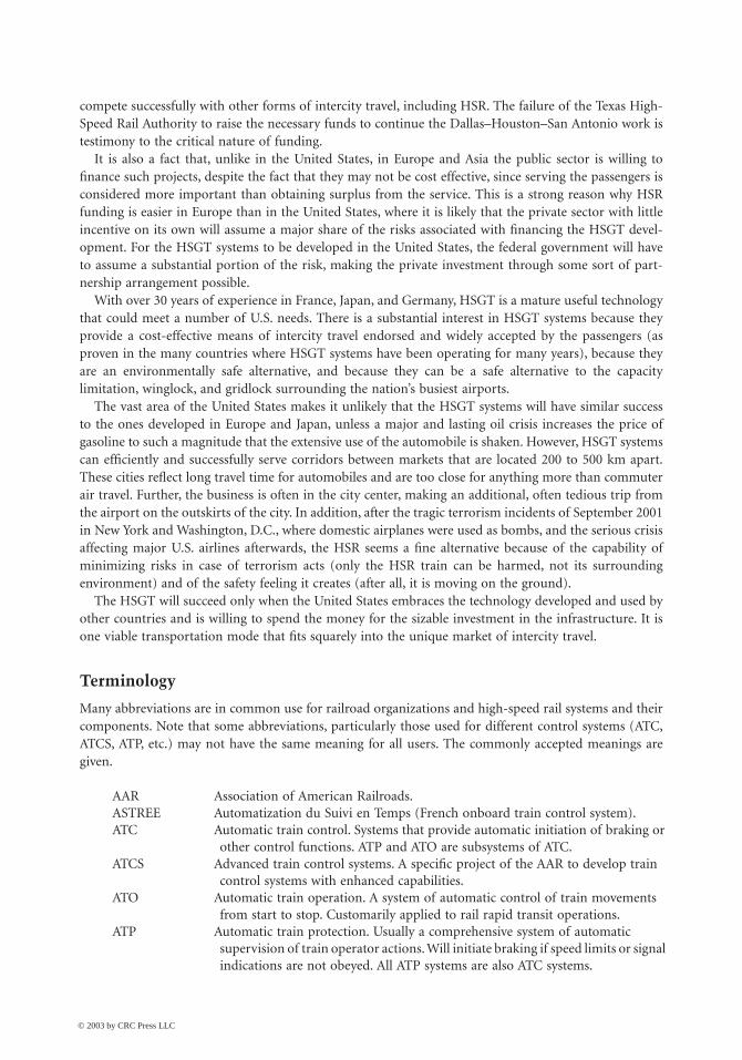
High-Speed Ground Transportation: Planning and Design Issues 60-37
compete successfully with other forms of intercity travel, including HSR. The failure of the Texas High-Speed Rail Authority to raise the necessary funds to continue the Dallas–Houston–San Antonio work istestimony to the critical nature of funding.
It is also a fact that, unlike in the United States, in Europe and Asia the public sector is willing tofinance such projects, despite the fact that they may not be cost effective, since serving the passengers isconsidered more important than obtaining surplus from the service. This is a strong reason why HSRfunding is easier in Europe than in the United States, where it is likely that the private sector with littleincentive on its own will assume a major share of the risks associated with financing the HSGT devel-opment. For the HSGT systems to be developed in the United States, the federal government will haveto assume a substantial portion of the risk, making the private investment through some sort of part-nership arrangement possible.
With over 30 years of experience in France, Japan, and Germany, HSGT is a mature useful technologythat could meet a number of U.S. needs. There is a substantial interest in HSGT systems because theyprovide a cost-effective means of intercity travel endorsed and widely accepted by the passengers (asproven in the many countries where HSGT systems have been operating for many years), because theyare an environmentally safe alternative, and because they can be a safe alternative to the capacitylimitation, winglock, and gridlock surrounding the nation’s busiest airports.
The vast area of the United States makes it unlikely that the HSGT systems will have similar successto the ones developed in Europe and Japan, unless a major and lasting oil crisis increases the price ofgasoline to such a magnitude that the extensive use of the automobile is shaken. However, HSGT systemscan efficiently and successfully serve corridors between markets that are located 200 to 500 km apart.These cities reflect long travel time for automobiles and are too close for anything more than commuterair travel. Further, the business is often in the city center, making an additional, often tedious trip fromthe airport on the outskirts of the city. In addition, after the tragic terrorism incidents of September 2001in New York and Washington, D.C., where domestic airplanes were used as bombs, and the serious crisisaffecting major U.S. airlines afterwards, the HSR seems a fine alternative because of the capability ofminimizing risks in case of terrorism acts (only the HSR train can be harmed, not its surroundingenvironment) and of the safety feeling it creates (after all, it is moving on the ground).
The HSGT will succeed only when the United States embraces the technology developed and used byother countries and is willing to spend the money for the sizable investment in the infrastructure. It isone viable transportation mode that fits squarely into the unique market of intercity travel.
Terminology
Many abbreviations are in common use for railroad organizations and high-speed rail systems and theircomponents. Note that some abbreviations, particularly those used for different control systems (ATC,ATCS, ATP, etc.) may not have the same meaning for all users. The commonly accepted meanings aregiven.
AAR Association of American Railroads.ASTREE Automatization du Suivi en Temps (French onboard train control system).ATC Automatic train control. Systems that provide automatic initiation of braking or
other control functions. ATP and ATO are subsystems of ATC.ATCS Advanced train control systems. A specific project of the AAR to develop train
control systems with enhanced capabilities.ATO Automatic train operation. A system of automatic control of train movements
from start to stop. Customarily applied to rail rapid transit operations.ATP Automatic train protection. Usually a comprehensive system of automatic
supervision of train operator actions. Will initiate braking if speed limits or signal indications are not obeyed. All ATP systems are also ATC systems.
© 2003 by CRC Press LLC
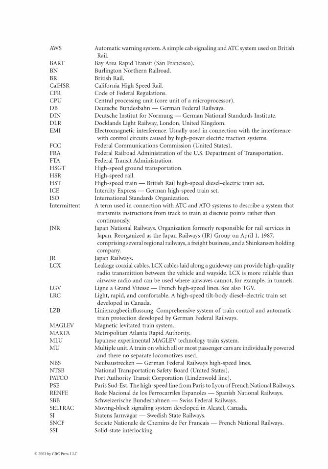
60-38 The Civil Engineering Handbook, Second Edition
AWS Automatic warning system. A simple cab signaling and ATC system used on British Rail.
BART Bay Area Rapid Transit (San Francisco).BN Burlington Northern Railroad.BR British Rail.CalHSR California High Speed Rail.CFR Code of Federal Regulations.CPU Central processing unit (core unit of a microprocessor).DB Deutsche Bundesbahn — German Federal Railways.DIN Deutsche Institut for Normung — German National Standards Institute.DLR Docklands Light Railway, London, United Kingdom.EMI Electromagnetic interference. Usually used in connection with the interference
with control circuits caused by high-power electric traction systems.FCC Federal Communications Commission (United States).FRA Federal Railroad Administration of the U.S. Department of Transportation.FTA Federal Transit Administration.HSGT High-speed ground transportation.HSR High-speed rail.HST High-speed train — British Rail high-speed diesel–electric train set.ICE Intercity Express — German high-speed train set.ISO International Standards Organization.Intermittent A term used in connection with ATC and ATO systems to describe a system that
transmits instructions from track to train at discrete points rather than continuously.
JNR Japan National Railways. Organization formerly responsible for rail services in Japan. Reorganized as the Japan Railways (JR) Group on April 1, 1987, comprising several regional railways, a freight business, and a Shinkansen holding company.
JR Japan Railways.LCX Leakage coaxial cables. LCX cables laid along a guideway can provide high-quality
radio transmittion between the vehicle and wayside. LCX is more reliable than airwave radio and can be used where airwaves cannot, for example, in tunnels.
LGV Ligne a Grand Vitesse — French high-speed lines. See also TGV.LRC Light, rapid, and comfortable. A high-speed tilt-body diesel–electric train set
developed in Canada.LZB Linienzugbeeinflussung. Comprehensive system of train control and automatic
train protection developed by German Federal Railways.MAGLEV Magnetic levitated train system.MARTA Metropolitan Atlanta Rapid Authority.MLU Japanese experimental MAGLEV technology train system.MU Multiple unit. A train on which all or most passenger cars are individually powered
and there no separate locomotives used.NBS Neubaustrecken — German Federal Railways high-speed lines.NTSB National Transportation Safety Board (United States).PATCO Port Authority Transit Corporation (Lindenwold line).PSE Paris Sud-Est. The high-speed line from Paris to Lyon of French National Railways.RENFE Rede Nacional de los Ferrocarriles Espanoles — Spanish National Railways.SBB Schweizerische Bundesbahnen — Swiss Federal Railways.SELTRAC Moving-block signaling system developed in Alcatel, Canada.SJ Statens Jarnvagar — Swedish State Railways.SNCF Societe Nationale de Chemins de Fer Francais — French National Railways.SSI Solid-state interlocking.
© 2003 by CRC Press LLC
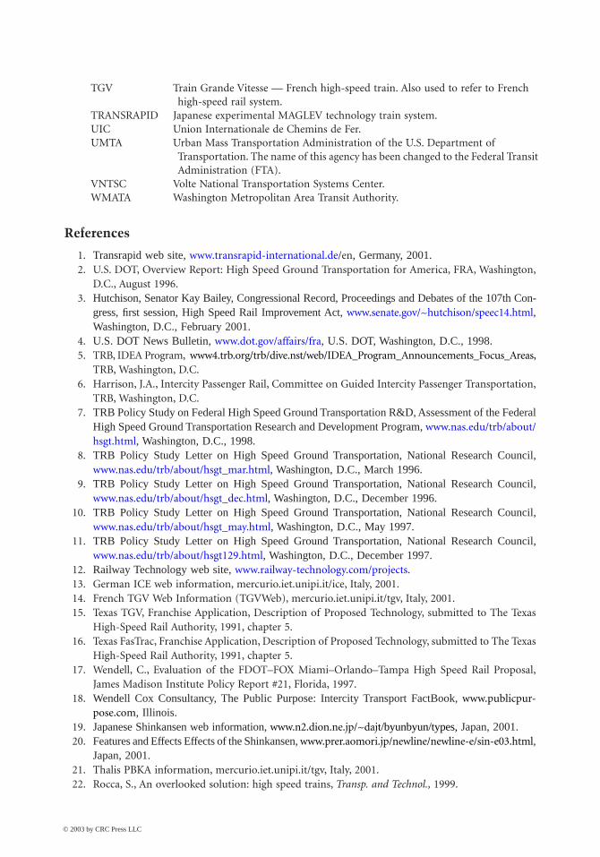
High-Speed Ground Transportation: Planning and Design Issues 60-39
References
1. Transrapid web site, www.transrapid-international.de/en, Germany, 2001.2. U.S. DOT, Overview Report: High Speed Ground Transportation for America, FRA, Washington,
D.C., August 1996.3. Hutchison, Senator Kay Bailey, Congressional Record, Proceedings and Debates of the 107th Con-
gress, first session, High Speed Rail Improvement Act, www.senate.gov/~hutchison/speec14.html,Washington, D.C., February 2001.
4. U.S. DOT News Bulletin, www.dot.gov/affairs/fra, U.S. DOT, Washington, D.C., 1998.5. TRB, IDEA Program, www4.trb.org/trb/dive.nst/web/IDEA_Program_Announcements_Focus_Areas,
TRB, Washington, D.C.6. Harrison, J.A., Intercity Passenger Rail, Committee on Guided Intercity Passenger Transportation,
TRB, Washington, D.C.7. TRB Policy Study on Federal High Speed Ground Transportation R&D, Assessment of the Federal
High Speed Ground Transportation Research and Development Program, www.nas.edu/trb/about/hsgt.html, Washington, D.C., 1998.
8. TRB Policy Study Letter on High Speed Ground Transportation, National Research Council,www.nas.edu/trb/about/hsgt_mar.html, Washington, D.C., March 1996.
9. TRB Policy Study Letter on High Speed Ground Transportation, National Research Council,www.nas.edu/trb/about/hsgt_dec.html, Washington, D.C., December 1996.
10. TRB Policy Study Letter on High Speed Ground Transportation, National Research Council,www.nas.edu/trb/about/hsgt_may.html, Washington, D.C., May 1997.
11. TRB Policy Study Letter on High Speed Ground Transportation, National Research Council,www.nas.edu/trb/about/hsgt129.html, Washington, D.C., December 1997.
12. Railway Technology web site, www.railway-technology.com/projects.13. German ICE web information, mercurio.iet.unipi.it/ice, Italy, 2001.14. French TGV Web Information (TGVWeb), mercurio.iet.unipi.it/tgv, Italy, 2001.15. Texas TGV, Franchise Application, Description of Proposed Technology, submitted to The Texas
High-Speed Rail Authority, 1991, chapter 5.16. Texas FasTrac, Franchise Application, Description of Proposed Technology, submitted to The Texas
High-Speed Rail Authority, 1991, chapter 5.17. Wendell, C., Evaluation of the FDOT–FOX Miami–Orlando–Tampa High Speed Rail Proposal,
James Madison Institute Policy Report #21, Florida, 1997.18. Wendell Cox Consultancy, The Public Purpose: Intercity Transport FactBook, www.publicpur-
pose.com, Illinois.19. Japanese Shinkansen web information, www.n2.dion.ne.jp/~dajt/byunbyun/types, Japan, 2001.20. Features and Effects Effects of the Shinkansen, www.prer.aomori.jp/newline/newline-e/sin-e03.html,
Japan, 2001.21. Thalis PBKA information, mercurio.iet.unipi.it/tgv, Italy, 2001.22. Rocca, S., An overlooked solution: high speed trains, Transp. and Technol., 1999.
TGV Train Grande Vitesse — French high-speed train. Also used to refer to French high-speed rail system.
TRANSRAPID Japanese experimental MAGLEV technology train system.UIC Union Internationale de Chemins de Fer.UMTA Urban Mass Transportation Administration of the U.S. Department of
Transportation. The name of this agency has been changed to the Federal Transit Administration (FTA).
VNTSC Volte National Transportation Systems Center.WMATA Washington Metropolitan Area Transit Authority.
© 2003 by CRC Press LLC
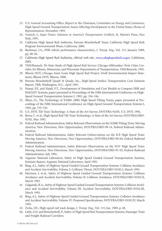
60-40 The Civil Engineering Handbook, Second Edition
23. U.S. General Accounting Office, Report to the Chairman, Committee on Energy and Commerce,High-Speed Ground Transportation: Issues Affecting Development in the United States, House ofRepresentatives, November 1993.
24. Vranich, J., Super-Trains: Solutions to America’s Transportation Gridlock, St. Martin’s Press, NewYork, 1991.
25. California High Speed Rail Authority, Parsons Brinckerhoff Team, California High Speed Rail:Program Environmental Phase, California, 2000.
26. Bachman, J.A., HSR vehicle performance characteristics, J. Transp. Eng., Vol. 115, January 1989,pp. 48–56.
27. California High Speed Rail Authority, official web site, www.cahighspeedrail.ca.gov, California,2001.
28. TMS/Benesch, Tri-State Study of High Speed Rail Service: Chicago–Milwaukee–Twin Cities Cor-ridor, for Illinois, Minnesota, and Wisconsin Departments of Transportation, TMS/Benesch, 1991.
29. Illinois DOT, Chicago–Saint Louis High Speed Rail Project: Draft Environmental Impact State-ment, Illinois DOT, Illinois, 2000.
30. Parsons Brinckerhoff Quade & Quade, Inc., High-Speed Surface Transportation Cost EstimateReport, TRB, Washington, D.C., April 1991.
31. Nassar, F.E. and Najafi, F.T., Development of Simulation and Cost Models to Compare HSR andMAGLEV Systems, paper presented at Proceedings of the Fifth International Conference on High-Speed Ground Transportation Systems I, 1992, pp. 336–346.
32. Silien, J.S., The Technology of X2000: ABB’s High Speed Tilting Trains, paper presented at Pro-ceedings of the Fifth International Conference on High-Speed Ground Transportation Systems I,1992, pp. 735–743.
33. U.S. DOT, Tilt Train Technology: A State of the Art Survey, DOT/FRA-92/05, U.S. DOT, 1992.34. Boon, C. et al., High Speed Rail Tilt Train Technology: A State of the Art Survey, DOT/FRA/ORD-
92/02, May 1992.35. Federal Railroad Administration, Safety Relevant Observations on the X2000 Tilting Train: Moving
America: New Directions, New Opportunities, DOT/FRA/ORD-90-14, Federal Railroad Admin-istration.
36. Federal Railroad Administration, Safety Relevant Oobservations on the ICE High Speed Train:Moving America: New Directions, New Opportunities, DOT/FRA/ORD-90-04, Federal RailroadAdministration.
37. Federal Railroad Administration, Safety Relevant Observations on the TGV High Speed Train:Moving America: New Directions, New Opportunities, DOT/FRA/ORD-91-03, Federal RailroadAdministration, July 1991.
38. Argonne National Laboratory, Safety of High Speed Guided Ground Transportation Systems,Estimate Report, Argonne National Laboratory, April 1991.
39. Bing, A.J., Safety of Highway Speed Guided Ground Transportation Systems: Collision Avoidanceand Accident Survivability, Volume I: Collision Threat, DOT/FRA/ORD-93/02.I, March 1993.
40. Harrison, J. et al., Safety of Highway Speed Guided Ground Transportation Systems: CollisionAvoidance and Accident Survivability, Volume II: Collision Avoidance, DOT/FRA/ORD-93/02.II,March 1993.
41. Galganski, R.A., Safety of Highway Speed Guided Ground Transportation Systems: Collision Avoid-ance and Accident Survivability, Volume III: Accident Survivability, DOT/FRA/ORD-93/02.III,March 1993.
42. Bing, A.J., Safety of Highway Speed Guided Ground Transportation Systems: Collision Avoidanceand Accident Survivability, Volume IV: Proposed Specifications, DOT/FRA/ORD-93/02.IV, March1993.
43. Zicha, J.H., High-speed rail track design, J. Transp. Eng., Vol. 115, Jan. 1989, p. 68.44. Little, A.D. and Brinckerhoff, P., Safety of High Speed Rail Transportation Systems, Passenger Train
and Freight Railroad Corridors.
© 2003 by CRC Press LLC

High-Speed Ground Transportation: Planning and Design Issues 60-41
45. Hadden, J. et al., Safety of High Speed Guided Ground Transportation Systems: Shared Right-of-Way Safety Issues, DOT/FRA/ORD-92/13, September 1992.
46. Canadian Institute of Guided Ground Transport, GEC-Alsthom/SNCF TGV Baseline, Draft Report,Queen’s University, 1992.
47. Zicha, J.H., High-Speed Rail Loading Scenario and Dynamic Tuning of Track, paper presented atProceedings of the Fifth International Conference on High-Speed Ground Transportation Systems I,1992, pp. 470–480.
48. Jenkins, H., Track maintenance for high-speed trains, Bull. AREA, 658, 499–521.49. Markos, S.H., Safety of High Speed Guided Ground Transportation Systems, Emergency Prepared-
ness Guidelines, DOT/FRA/ORD-93/24, December 1993.50. National Institute of Standards and Technology (NIST), Fire Safety of Passenger Trains: A Review
of U.S. and Foreign Approaches, DOT/FRA/ORD-93/23, December 1993.51. Reich and Bessoir, Safety of Vital Control and Communication Systems in Guided Ground Trans-
portation: Analysis of Railroad Signaling System: Microprocessor Interlocking, DOT/FRA-ORD-93/08, May 1993.
52. Battelle, Safety of High Speed Guided Ground Transportation Systems, Safety Verification/Valida-tion Methodologies for Vital Computer Systems.
53. MIT, Safety of High Speed Guided Ground Transportation Systems, Human Factors and Automation.54. FRA/Volpe Center, High-Speed Ground Transportation Bibliography, Volpe National Transporta-
tion Systems Center, August 1994.55. Wayson, R.L. and Bowlby, W., Noise and air pollution of high-speed rail systems, J. Transp. Eng.,
Vol. 115, Jan. 1989, pp. 20–36.56. Taille, J.Y., The TGV Network and the Environment, paper presented at Proceedings of the Fifth
International Conference on High-Speed Ground Transportation Systems I, 1992, pp. 136–145.57. Hall, M.S. and Wayson, R.L., A Combined Model for HSGT Traffic, paper presented at Proceedings
of the Fifth International Conference on High-Speed Ground Transportation Systems I, 1992,pp. 176–188.
58. Isbell, T.S., Concurrent Engineering Planning in HSGT Systems, paper presented at Proceedingsof the Fifth International Conference on High-Speed Ground Transportation Systems I, 1992,pp. 457–467.
59. AREA, AREA Manual for Railway Engineering, 1992. 60. Hay, W.W., Railroad Engineering, 2nd Ed., Wiley, New York, 1982.61. Knutton, M., Air/Rail Collaboration: Heaven or Hell?, Railway Age, www.railwayage.com/sept
01/movingpeople.html, United States, September 2001.62. Wright, P.H. and Ashford, N.J., Transportation Engineering Planning and Design, 3rd ed., John
Wiley & Sons, New York, 1989.63. Wakui, H. and Matsumoto, N., Dynamic Study on New Guideway Structure for JR MAGLEV,
paper presented at Proceedings of the Fifth International Conference on High-Speed GroundTransportation Systems I, 1992, pp. 487–496.
64. Hardgrove, M.S. and Mason, J., Estimating the Ground Transportation Impacts of the MAGLEVSystem, paper presented at Proceedings of the Fifth International Conference on High-SpeedGround Transportation Systems I, 1992, pp. 199–208.
65. Shinkansen News, www.n2.dion.ne.jp/byunbyun/news.htm, Japan, 2001.66. Witt, M.H., Application of the MAGLEV System in Germany, paper presented at Proceedings of the
Fifth International Conference on High-Speed Ground Transportation Systems I, 1992, pp. 707–722.67. Wackers, M., The Transrapid MAGLEV System, paper presented at Proceedings of the Fifth Inter-
national Conference on High-Speed Ground Transportation Systems I, 1992, pp. 724–734.68. Dickhart, W.W. and Pavlick, M., MAGLEV sky train, Mech. Eng., 1984, Vol. 106, No.1.69. Sara, C.M., Plan for Development and Implementation of a Domestic MAGLEV Network, paper
presented at Proceedings of the Fifth International Conference on High-Speed Ground Transpor-tation Systems I, 1992, pp. 638–647.
© 2003 by CRC Press LLC
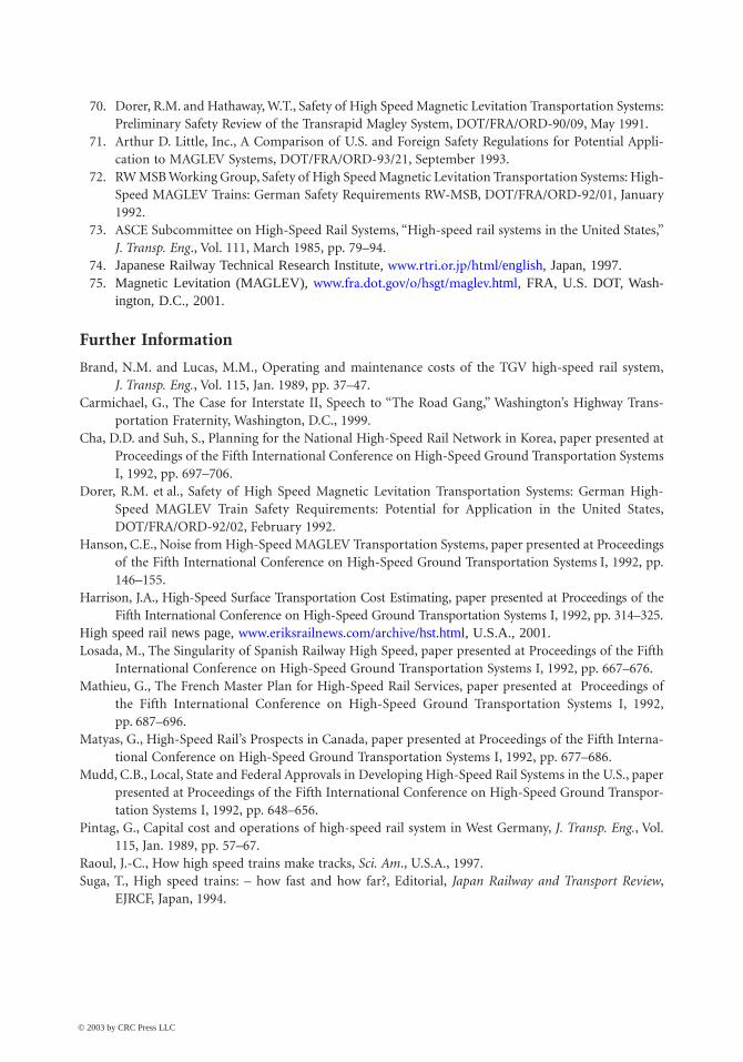
60-42 The Civil Engineering Handbook, Second Edition
70. Dorer, R.M. and Hathaway, W.T., Safety of High Speed Magnetic Levitation Transportation Systems:Preliminary Safety Review of the Transrapid Magley System, DOT/FRA/ORD-90/09, May 1991.
71. Arthur D. Little, Inc., A Comparison of U.S. and Foreign Safety Regulations for Potential Appli-cation to MAGLEV Systems, DOT/FRA/ORD-93/21, September 1993.
72. RW MSB Working Group, Safety of High Speed Magnetic Levitation Transportation Systems: High-Speed MAGLEV Trains: German Safety Requirements RW-MSB, DOT/FRA/ORD-92/01, January1992.
73. ASCE Subcommittee on High-Speed Rail Systems, “High-speed rail systems in the United States,”J. Transp. Eng., Vol. 111, March 1985, pp. 79–94.
74. Japanese Railway Technical Research Institute, www.rtri.or.jp/html/english, Japan, 1997.75. Magnetic Levitation (MAGLEV), www.fra.dot.gov/o/hsgt/maglev.html, FRA, U.S. DOT, Wash-
ington, D.C., 2001.
Further Information
Brand, N.M. and Lucas, M.M., Operating and maintenance costs of the TGV high-speed rail system,J. Transp. Eng., Vol. 115, Jan. 1989, pp. 37–47.
Carmichael, G., The Case for Interstate II, Speech to “The Road Gang,” Washington’s Highway Trans-portation Fraternity, Washington, D.C., 1999.
Cha, D.D. and Suh, S., Planning for the National High-Speed Rail Network in Korea, paper presented atProceedings of the Fifth International Conference on High-Speed Ground Transportation SystemsI, 1992, pp. 697–706.
Dorer, R.M. et al., Safety of High Speed Magnetic Levitation Transportation Systems: German High-Speed MAGLEV Train Safety Requirements: Potential for Application in the United States,DOT/FRA/ORD-92/02, February 1992.
Hanson, C.E., Noise from High-Speed MAGLEV Transportation Systems, paper presented at Proceedingsof the Fifth International Conference on High-Speed Ground Transportation Systems I, 1992, pp.146–155.
Harrison, J.A., High-Speed Surface Transportation Cost Estimating, paper presented at Proceedings of theFifth International Conference on High-Speed Ground Transportation Systems I, 1992, pp. 314–325.
High speed rail news page, www.eriksrailnews.com/archive/hst.html, U.S.A., 2001.Losada, M., The Singularity of Spanish Railway High Speed, paper presented at Proceedings of the Fifth
International Conference on High-Speed Ground Transportation Systems I, 1992, pp. 667–676.Mathieu, G., The French Master Plan for High-Speed Rail Services, paper presented at Proceedings of
the Fifth International Conference on High-Speed Ground Transportation Systems I, 1992,pp. 687–696.
Matyas, G., High-Speed Rail’s Prospects in Canada, paper presented at Proceedings of the Fifth Interna-tional Conference on High-Speed Ground Transportation Systems I, 1992, pp. 677–686.
Mudd, C.B., Local, State and Federal Approvals in Developing High-Speed Rail Systems in the U.S., paperpresented at Proceedings of the Fifth International Conference on High-Speed Ground Transpor-tation Systems I, 1992, pp. 648–656.
Pintag, G., Capital cost and operations of high-speed rail system in West Germany, J. Transp. Eng., Vol.115, Jan. 1989, pp. 57–67.
Raoul, J.-C., How high speed trains make tracks, Sci. Am., U.S.A., 1997.Suga, T., High speed trains: – how fast and how far?, Editorial, Japan Railway and Transport Review,
EJRCF, Japan, 1994.
© 2003 by CRC Press LLC

![airport ground trans. [permit] - flysanjose.com · revision 2015.12.09 ground transportation permit for ground transportation providers coming onto norman y. mineta san jose international](https://img.dokumen.tips/doc/110x75/5bfdda0b09d3f295268b7376/airport-ground-trans-permit-revision-20151209-ground-transportation-permit.jpg)