Embed Size (px)
Citation preview

UNIVERSITY PHYSICS Chapter 5 ELECTRIC CHARGES AND FIELDS
PowerPoint Image Slideshow

FIGURE 5.1
Electric charges exist all around us. They can cause objects to be repelled from each
other or to be attracted to each other. (credit: modification of work by Sean McGrath)
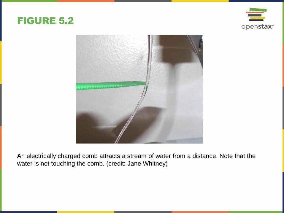
FIGURE 5.2
An electrically charged comb attracts a stream of water from a distance. Note that the
water is not touching the comb. (credit: Jane Whitney)
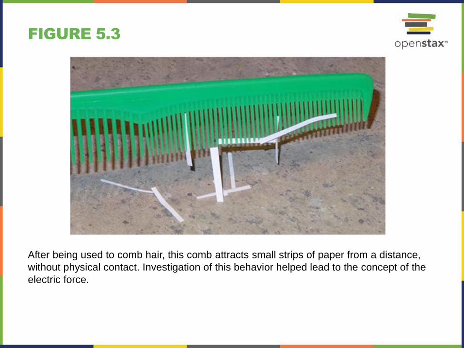
FIGURE 5.3
After being used to comb hair, this comb attracts small strips of paper from a distance,
without physical contact. Investigation of this behavior helped lead to the concept of the
electric force.

FIGURE 5.4
Borneo amber is mined in Sabah, Malaysia, from shale-sandstone-mudstone veins.
When a piece of amber is rubbed with a piece of fur, the amber gains more electrons,
giving it a net negative charge. At the same time, the fur, having lost electrons,
becomes positively charged. (credit: “Sebakoamber”/Wikimedia Commons)

FIGURE 5.5
When materials are rubbed together, charges can be separated, particularly if one material has a greater affinity for electrons than another.
(a) Both the amber and cloth are originally neutral, with equal positive and negative charges. Only a tiny fraction of the charges are involved, and
only a few of them are shown here.
(b) When rubbed together, some negative charge is transferred to the amber, leaving the cloth with a net positive charge.
(c) When separated, the amber and cloth now have net charges, but the absolute value of the net positive and negative charges will be equal.

FIGURE 5.6
A Leyden jar (an early version of what is
now called a capacitor) allowed
experimenters to store large amounts of
electric charge. Benjamin Franklin used
such a jar to demonstrate that lightning
behaved exactly like the electricity he got
from the equipment in his laboratory.

FIGURE 5.7
This simplified model of a hydrogen atom shows a positively charged nucleus (consisting, in the case of
hydrogen, of a single proton), surrounded by an electron “cloud.” The charge of the electron cloud is equal
(and opposite in sign) to the charge of the nucleus, but the electron does not have a definite location in
space; hence, its representation here is as a cloud. Normal macroscopic amounts of matter contain
immense numbers of atoms and molecules, and, hence, even greater numbers of individual negative and
positive charges.

FIGURE 5.8
The nucleus of a carbon atom is composed of six protons and six neutrons. As in
hydrogen, the surrounding six electrons do not have definite locations and so can be
considered to be a sort of cloud surrounding the nucleus.
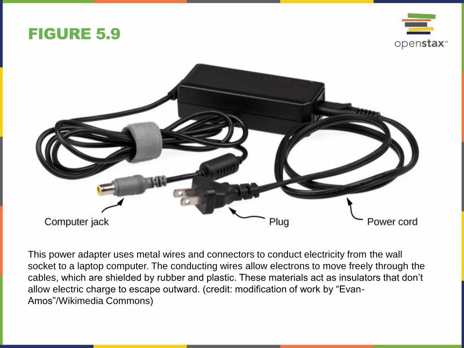
FIGURE 5.9
This power adapter uses metal wires and connectors to conduct electricity from the wall
socket to a laptop computer. The conducting wires allow electrons to move freely through the
cables, which are shielded by rubber and plastic. These materials act as insulators that don’t
allow electric charge to escape outward. (credit: modification of work by “Evan-
Amos”/Wikimedia Commons)

FIGURE 5.10
Induced polarization. A positively charged glass rod is brought near the left side of the
conducting sphere, attracting negative charge and leaving the other side of the sphere
positively charged. Although the sphere is overall still electrically neutral, it now has a charge
distribution, so it can exert an electric force on other nearby charges. Furthermore, the
distribution is such that it will be attracted to the glass rod.

FIGURE 5.11
Both positive and negative objects attract a neutral object by polarizing its molecules.
(a) A positive object brought near a neutral insulator polarizes its molecules. There is a slight shift in the distribution of the electrons orbiting
the molecule, with unlike charges being brought nearer and like charges moved away. Since the electrostatic force decreases with
distance, there is a net attraction.
(b) A negative object produces the opposite polarization, but again attracts the neutral object.
(c) The same effect occurs for a conductor; since the unlike charges are closer, there is a net attraction.

FIGURE 5.12
Charging by induction.
(a) Two uncharged or neutral metal
spheres are in contact with each
other but insulated from the rest of
the world.
(b) A positively charged glass rod is
brought near the sphere on the left,
attracting negative charge and
leaving the other sphere positively
charged.
(c) The spheres are separated before
the rod is removed, thus separating
negative and positive charges.
(d) The spheres retain net charges after
the inducing rod is removed—without
ever having been touched by a
charged object.

FIGURE 5.13
Charging by induction using a ground connection.
(a) A positively charged rod is brought near a neutral metal sphere, polarizing it.
(b) The sphere is grounded, allowing electrons to be attracted from Earth’s ample supply.
(c) The ground connection is broken.
(d) The positive rod is removed, leaving the sphere with an induced negative charge.
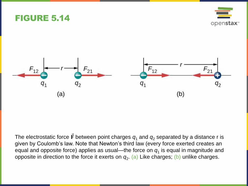
FIGURE 5.14
The electrostatic force 𝐅 between point charges q1 and q2 separated by a distance r is
given by Coulomb’s law. Note that Newton’s third law (every force exerted creates an
equal and opposite force) applies as usual—the force on q1 is equal in magnitude and
opposite in direction to the force it exerts on q2. (a) Like charges; (b) unlike charges.

FIGURE 5.15
A schematic depiction of a hydrogen
atom, showing the force on the electron.
This depiction is only to enable us to
calculate the force; the hydrogen atom
does not really look like this. Recall
Figure 5.7.

FIGURE 5.16
The eight source charges each apply a force on the single test charge Q. Each force
can be calculated independently of the other seven forces. This is the essence of the
superposition principle.

FIGURE 5.17
Source charges q1 and q3 each apply a force on q2.

FIGURE 5.18
Each of these eight source charges creates its own electric field at every point in space;
shown here are the field vectors at an arbitrary point P. Like the electric force, the net
electric field obeys the superposition principle.

FIGURE 5.19
A schematic representation of a helium
atom. Again, helium physically looks
nothing like this, but this sort of diagram
is helpful for calculating the electric field
of the nucleus.

FIGURE 5.20
Finding the field of two identical source charges at the point P. Due to the symmetry,
the net field at P is entirely vertical. (Notice that this is not true away from the midline
between the charges.)

FIGURE 5.21
Note that the horizontal components of
the electric fields from the two charges
cancel each other out, while the vertical
components add together.

FIGURE 5.22
The configuration of charge differential elements for a (a) line charge, (b) sheet of
charge, and (c) a volume of charge. Also note that (d) some of the components of the
total electric field cancel out, with the remainder resulting in a net electric field.

FIGURE 5.23
A uniformly charged segment of wire. The electric field at point P can be found by
applying the superposition principle to symmetrically placed charge elements and
integrating.

FIGURE 5.24
The system and variable for calculating
the electric field due to a ring of charge.
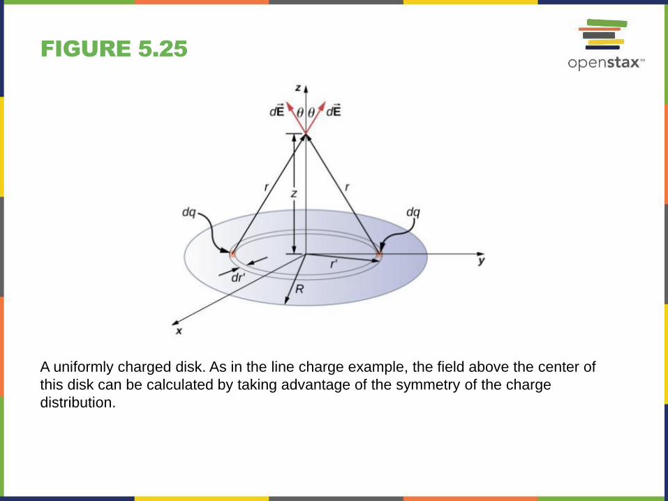
FIGURE 5.25
A uniformly charged disk. As in the line charge example, the field above the center of
this disk can be calculated by taking advantage of the symmetry of the charge
distribution.

FIGURE 5.26
Two charged infinite planes. Note the
direction of the electric field.
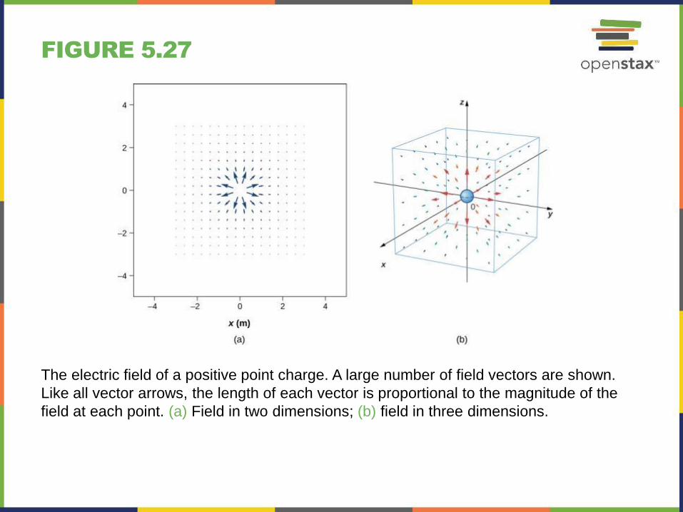
FIGURE 5.27
The electric field of a positive point charge. A large number of field vectors are shown.
Like all vector arrows, the length of each vector is proportional to the magnitude of the
field at each point. (a) Field in two dimensions; (b) field in three dimensions.

FIGURE 5.28
The vector field of a dipole. Even with
just two identical charges, the vector field
diagram becomes difficult to understand.

FIGURE 5.29
(a) The electric field line diagram of a positive point charge.
(b) The field line diagram of a dipole. In both diagrams, the magnitude of the field is indicated by the field line density. The field vectors (not shown here) are everywhere tangent to the field lines.

FIGURE 5.30
Electric field lines passing through imaginary areas. Since the number of lines passing
through each area is the same, but the areas themselves are different, the field line
density is different. This indicates different magnitudes of the electric field at these
points.

FIGURE 5.31
Three typical electric field diagrams.
(a) A dipole.
(b) Two identical charges.
(c) Two charges with opposite signs and different magnitudes. Can you tell from the diagram which charge has the
larger magnitude?

FIGURE 5.32
A dipole in an external electric field.
(a) The net force on the dipole is zero, but the net torque is not. As a result, the dipole rotates, becoming aligned with
the external field.
(b) The dipole moment is a convenient way to characterize this effect. The 𝐝 points in the same direction as 𝐩.

FIGURE 5.33
A dipole is induced in a neutral atom by an external electric field. The induced dipole
moment is aligned with the external field.

FIGURE 5.34
The net electric field is the vector sum of the field of the dipole plus the external field.
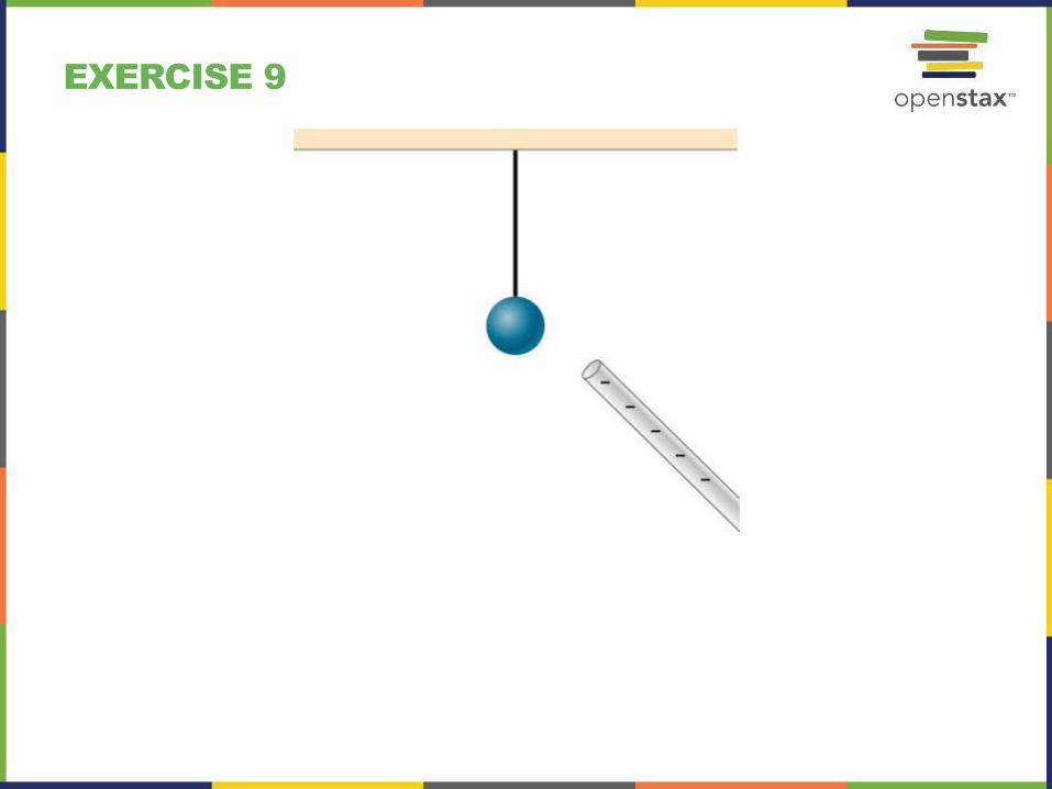
EXERCISE 9

EXERCISE 55

EXERCISE 59

EXERCISE 60

EXERCISE 62

EXERCISE 63

EXERCISE 68

EXERCISE 83

EXERCISE 84

EXERCISE 87

EXERCISE 90

EXERCISE 94

EXERCISE 95

EXERCISE 96

EXERCISE 97

EXERCISE 98
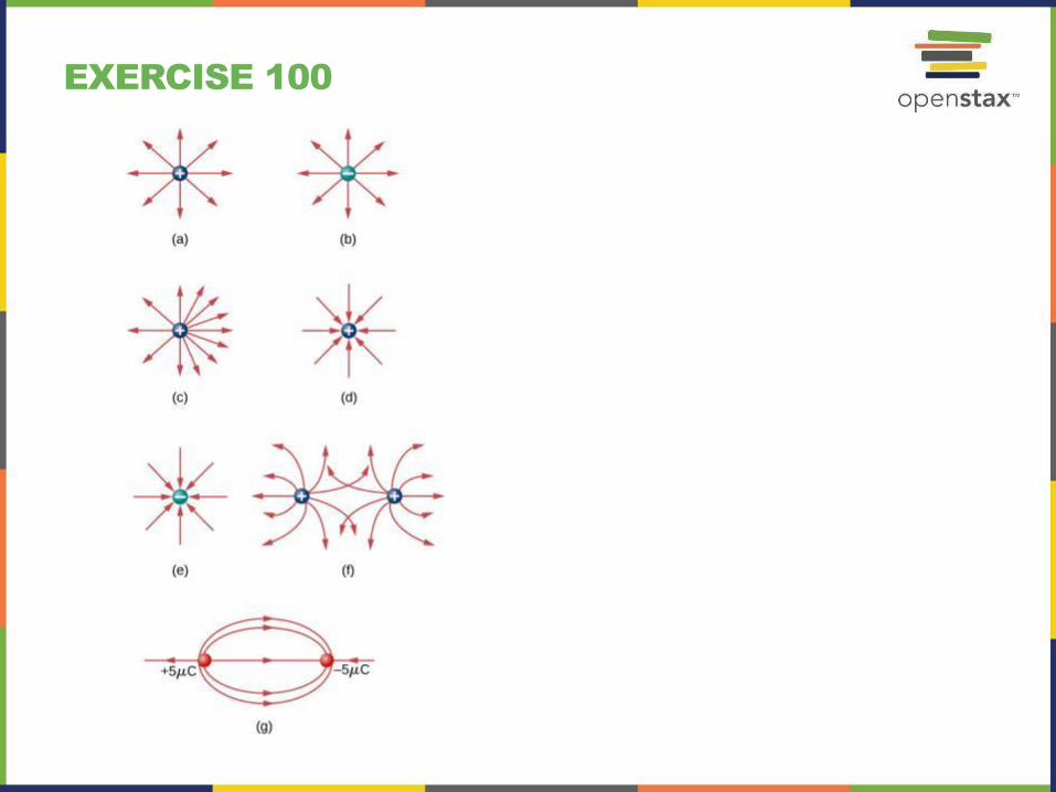
EXERCISE 100
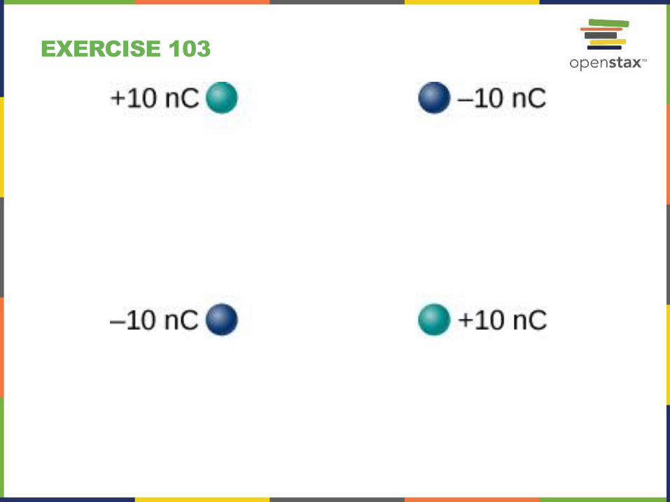
EXERCISE 103

EXERCISE 105

EXERCISE 107

EXERCISE 109

EXERCISE 110

EXERCISE 111

EXERCISE 112
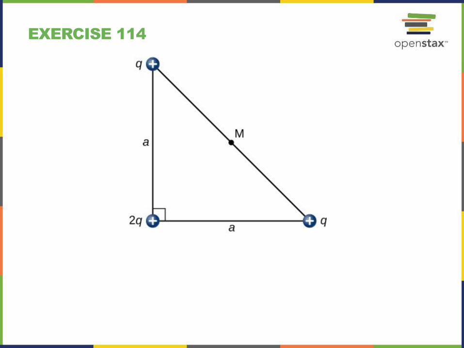
EXERCISE 114

EXERCISE 115

EXERCISE 116

EXERCISE 117

EXERCISE 118

EXERCISE 122
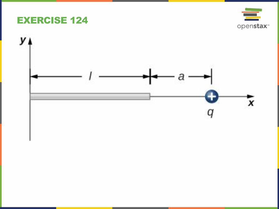
EXERCISE 124

EXERCISE 125
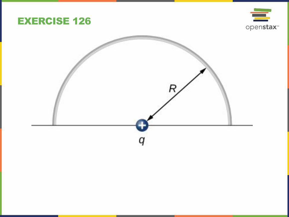
EXERCISE 126

This OpenStax ancillary resource is © Rice University under a CC-BY 4.0 International
license; it may be reproduced or modified but must be attributed to OpenStax, Rice
University and any changes must be noted.